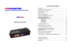
1
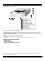
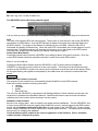
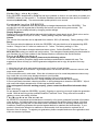
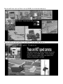
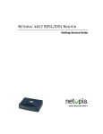
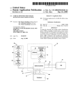
by RoadPilot ltd
43 Riverside 2
Sir Thomas Longley Road
Rochester
Kent
ME2 4DP
USER GUIDE
Version 3.8 (22.07)
WWW.ROADPILOT.COM
T: 0870 2401702
F: 0870 2401704
E: [email protected]
Please complete and return the registration from the centre of this booklet
Geodesy User Guide Amendments
Power Clip:
As of the 1 st October 2002 Geodesy Kits are shipped with one Cigarette Power Clip only. If you
wish to purchase an additional Power Clip, please call us on 0870 2401702.
Modem Usage:
Do NOT leave your Geodesy in the modem base connected to your telephone line for more
than 30 minutes a day.
RoadPilot will not be held responsible for long periods of telephone connectivity.
Finder’s Fee:
As of 1 st May 2004 the finder’s fee shall be a credit of £20.00 to your RoadPilot account
Serial Interface:
From August 2003 a serial interface to a standard PC (not Apple compatible) is available. This
enables downloads to be performed via the internet. This process can be faster and cost less
than using a modem to update your Geodesy unit.
Operating Voltage:
Geodesy is designed to operate on 12VDC power supplies only (9.5 – 15VDC)
GEODESY User Guide
User GuIde Contents
Introduction to the GEODESY
Setting Up
Positioning
Motor Vehicle Installation
Motorcycle Installation
Operating the GEODESY
Status Indicator
Alarm Display and Sounder
Audio Mute Button
User Locations
Database Credit Incentive
Database Update
Desktop Modem
Updating: Step by Step Guide
Geodesy Plus Features
Accessories/Optional Extras
Specifications
Glossary
Trouble Shooting
Customising the GEODESY
Care and Maintenance
Servicing
The RoadPilot Guarantee
Cameras covered by the GEODESY
Cameras NOT covered by the GEODESY
2
3
3
3
3
4
4
5
5
5
6
6
6
6
7
8
9
9
10
11
11
11
11
12
12
Technical Information Helpline
Answers to technical queries and advice is available on the technical information help line on 0870
2401702.
Returns PolIcy
If you experience technical problems, please call RoadPilot on 0870 2401701 for advice, if you need to
return the equipment a returns number (RMA) must be obtained before sending your unit back.
page one
GEODESY User Guide
GEODESY at a Glance
IntroductIon to the GEODESY
By bringing together the latest satellite technology and a vast range of flexible services and features,
GEODESY puts you in control of the way you use Britain's roads. With GEODESY, you have the choice
to protect your licence and your life.
GEODESY: A unique dimension in driving safety.
GEODESY uses state-of-the-art satellite technology.
The GEODESY is a complete and reliable solution to fixed point Speed Detection Devices.
GEODESY: High quality warning system.
No False Alarms.
No last minute warnings.
Reliable, accurate and consistent operation.
N.B. Unless you are using a re-radiating antenna the Geodesy must be installed with the
domed section facing upwards.
page two
GEODESY User Guide
SettIng up the GEODESY
Positioning
The GEODESY must have a clear view of the sky for the system to work. The greater the exposure, the
better the performance. In a car we recommend that you place the GEODESY on the dashboard. On a
motorcycle we recommend that you place the GEODESY on the underside of your screen. It is vital to
install the GEODESY where it will not interfere with your safe operation of the vehicle controls and where
it will not obstruct your view of the road. You can use the re-radiating external antenna (optional extra)
to mount the GEODESY elsewhere. It is recommended that fitting be done professionally.
Please note that the Geodesy must be mounted with the raised section facing upwards.
Check that your GEODESY Kit is complete
When you unpack you must have:
1 GEODESY unit
2 Scotch Clips
1 240V Power Supply
1 Telephone Adapter
1 Telephone Extension Cable
1 Desktop Modem
1 Power Clip 12VDC
2 Adhesive Pads
2 Alcohol Wipes
General
Please do not attempt permanent installation unless you are competent to do so. Modern cars and
motorcycles often have complex and delicate electrical systems, which could be damaged if care is not
taken. Refer to a professional installer where there is any doubt. Please ensure that self-fitting of this
device does not invalidate any vehicle manufacturer's warranty. Please note RoadPilot Ltd accepts no
responsibility for damage caused by fitting to either the vehicle or any of its components.
Motor VehIcle InstallatIon
Power Clip with Cigarette Connector
Step1 Select the appropriate square block adhesive pad to suit the installation.
Step2 Clean the underside of the power clip and the dashboard with alcohol wipe.
Step3 Stick the adhesive pad to the underside of the power clip, position it on the dashboard and
press firmly.
Step4 Insert the cigarette lighter plug into the vehicle's cigarette lighter socket (some cars require the
ignition to be 'ON').
See next section for permanent wiring details.
Step5 Slot the GEODESY into the power clip.
Your GEODESY is now ready to use. When leaving the vehicle, remove the GEODESY from the power
clip by gently squeezing the side of the clip to release the locking catch at the top of the clip. You can
then slide the Geodesy out of its clip.
NOTE
The GEODESY may take up to 45 minutes before coming online for the first time (cold start). Thereafter
it will only take a few minutes to re-establish the satellite communication link. Geodesy is operable in
England, Scotland and Wales.
page three
GEODESY User Guide
Motorcycle InstallatIon
Step1
Step2
Step3
Step4
Select the appropriate rounded adhesive pad to suit the installation
Cut off the cigarette lighter plug from the power clip then clean the top of the power clip, and the
screen, with the alcohol wipe. Make sure that visibility is not obscured and that you can see
your instruments clearly.
Feed the cable from the GEODESY through to the back of your instruments or to your wiring
loom. Safely ensure that the cable does not interfere with the operation of the motorcycle
controls or steering system.
Locate the two power supply wires from your wiring loom. One of these must be a permanent
ground (usually
black) and the other needs to be power (usually red, yellow, blue, blue/red, brown/blue,
red/black, red/white).
One of the wires from a front indicator is usually ground (black) and one of the two wires on the brake
light switch is usually positive (brown). You may now cut the GEODESY wire to length, or split the wire
and cut to different lengths as appropriate. Make sure that there is just enough slack so that there is no
tension on any wires.
Step5
Now use two of the self stripping connectors (scotch clips) to fix the GEODESY wires to the
motorcycle wires by clamping the scotch clips with pliers.
TIP
The GEODESY draws very little current and is non-polar i.e. it does not matter which wire goes to
positive and which goes to negative.
Step6
Slot the GEODESY into the power clip.
Your GEODESY is now ready to use. When leaving the vehicle, remove the GEODESY from the power
clip by gently squeezing the side of the clip to release the locking catch at the top of the clip. You can
then slide the Geodesy out of its clip.
NOTE
The GEODESY may take up to 45 minutes before coming online for the first time (cold start). Thereafter
it will only take a few minutes to re-establish the satellite communication link. Geodesy is operable in
England, Scotland and Wales.
OperatIng the GEODESY
Having inserted the GEODESY into its power clip, all the operations (except manually storing a user
location) are automatic. The unit keeps the user informed as to its operative status by means of the
LEDs on the front panel.
Status Indicator
The two lights on the left are the status indicators. The blue light shows that the GEODESY is online,
and receiving satellite signals. The red light indicates the power is on.
The GEODESY initialising (Power Indicator)
red
page four
GEODESY User Guide
Motorcycle InstallatIon
The GEODESY Online (Receiving satellite signal)
blue
If at any time you have any of the scale of ten lights showing, you may be within range of a camera site.
SDD
The scale of ten display LEDs are warning lights. These count up from the left in red as the GEODESY
approaches an SDD location. One red LED indicates a distance one tenth of the selected distance to
the SDD location. Two tenths of the distance is indicated by two red LEDs. When the fifth LED is
illuminated, the display will flash slowly. When the sixth LED is illuminated, the sounder begins to emit a
warning tone. The flashes and tone will increase in frequency, as you get closer to the SDD location.
Once the SDD location has been passed, the display counts down in green.
Audio Alarm Mute Button
Pressing the brass button whilst the GEODESY is sounding an alarm will mute the sounder. Once the
current SDD location has been passed the sounder is active for the next SDD location.
User LocatIons
Pressing the Brass Report Button whilst the GEODESY is NOT in alarm status will enable the
GEODESY to store the current location as a new user location. The button must be held down at the
location as the GEODESY counts to ten (shown by the individual count of the scale of ten display LEDs).
All ten lights flashing red together accompanied by an audible tone will confirm the location has been
stored.
NOTE
When the report button is pressed
The purpose of user locations is to automatically advise RoadPilot of new SDD locations.
Each user location stores the following information:
• Latitude
• Longitude
• Speed
• Date and Time
The next time the GEODESY is connected to the Desktop Modem or Serial Interface; all the new user
locations are uploaded to the RoadPilot Network. RoadPilot will then act upon this new information,
validating each new location before entering it into the system.
Database Credit Incentive
Be part of our winning team. Help us identify new speed camera installations. The first GEODESY user
to report a new SDD will receive a credit to their RoadPilot account. Having logged a new SDD location,
please call the Database Hotline 0870 2401702 with clear details of the new SDD site. Please include
town & village/ road name & number/ speed zone/ camera type & direction. This speeds up the reliability
and accuracy of validating the database.
Credit incentives will be subject to the correct registration of the Geodesy. Due to validation,
credits may take 12 weeks to process.
page five
GEODESY User Guide
Database Update
Since new SDD locations are installed and mobile SDD locations relocated, typically at road works, a
regular download/update is advised. To update the database, simply insert the GEODESY into the
Desktop Modem. Once an update is complete, the GEODESY will display all ten scale lights in green.
NOTE
The GEODESY will only dial if the line is free.
The GEODESY will not interrupt a busy line but will test for a free line every two minutes. To avoid this
process simply remove the GEODESY from the Desktop Modem.
Once an update is complete, or in the event of difficulties in making a connection do not leave the
GEODESY unattended in the Modem base. Morpheous/RoadPilot Limited take no responsibility for
phone bills if the equipment is left unattended and makes multiple attempts to download data. Please
update at least once a week.
Update ServIce
The update service is free for the first six months following purchase and £50.00 incl VAT per year
thereafter. Failure to renew your update service in advance of your expiry date will affect the operation
of your GEODESY
Desktop Modem
Once inserted into the Desktop Modem, the GEODESY goes through a sequence of events before
dialing. The power indicator shows these as follows:
Green
Green
All 10 Scale Lights
Green
9th Scale Light
Blue
Flashing
The GEODESY is waiting for the connection to the
telephone network
The GEODESY has completed all database updates
and uploaded new locations to the RoadPilot network.
The GEODESY is ready for use.
The GEODESY will dial 9 first (press the button to
delete the dial 9 action)
The GEODESY is online with the RoadPilot network.
UpdatIng: step by step
Step1 Make sure that the Desktop Modem is correctly installed i.e. the power and telephone line are
connected
Step2 Insert the GEODESY into the Modem until you hear a click. You should only be able to remove it
from the Modem by depressing the button on the Modem.
If the option to dial 9 for an outside line has been set, then the 9th scale light is displayed green.
To
turn this off press the button. The GEODESY will reboot and dial the RoadPilot network without
using a 9 first (such as a home telephone line). To turn on press the button until the 9th light is
illuminated
Step4 The blue flashing light shows the Modem is online (All lights may go out for approx. 30 sec before
the blue light starts flashing)
Step5 The Modem completes all communication, disconnects and displays all ten scale lights as green.
The GEODESY returns to Step3 every two minutes until updated. If any of the display LED lights
are showing red, then the GEODESY cannot dial because of one of the following errors:
page six
GEODESY User Guide
DIal–up Errors Codes
LED No.
3
4
6
7
8
Colour
Error
Red
No Line Carrier
Red
Modem Error
Red
No Dial Tone
Red
Red
Line Busy
No Answer
Action
No Line detected. Check cable connections to modem and phone socket
Modem faulty. Call RoadPilot Help line 0870 2401702
Check telephone socket is connected correctly. Note line must be
analogue no connection is possible on digital or BT Highway lines
Check with your telephone company that the line gain is at maximum.
Check answer phone or internet connections are not interfering in line
RoadPilot server temporarily offline. Wait and try again later.
RegIsterIng GEODESY OwnershIp
Please validate your GEODESY guarantee by carefully removing this centre registration form and
returning it in the prepaid envelope provided. This will enable RoadPilot to activate your personalised
account and improve customer service. These details will serve to streamline the customer Database
and provide customer demographics for RoadPilot records.
Please note Retail/Dealership/Catalogue sales must register personal details with RoadPilot to open a
GEODESY account.
Registration documents MUST be returned within 7 days of purchase
RoadPilot is registered with the Data Protection Act and all information provided will be for the sole use
of the Marketing Department only and will NOT be divulged to a third party.
RoadPilot to use this information as described above.
q Yes
q No
Thank you.
Remove & Return
Remove & Return
Remove & Return
Remove & Return
Remove
GEODESY User Guide
RegIsterIng GEODESY OwnershIp
Today’s Date:
Title:
First Name:
Surname:
Postal Address:
Day Telephone no:
Evening Telephone no:
Mobile no:
Fax no:
Email Address:
Post Code:
(Please include zeros as these denote the batch number)
GEODESY Serial no:
How did you learn about the GEODESY?
How did you purchase the GEODESY?
q RoadPilot Telephone Sales
q Fax Order Form
q RoadPilot Website
q Dealer
Name of Dealer
q RoadPilot Exhibition
q Retail
Name of Retailer
q Catalogue
Name of Catalogue
Purchase Date
Please attach proof of purchase if not bought directly from RoadPilot.
Copy proof of purchase will validate your RoadPilot guarantee.
Payment Method
q Cash
q Cheque
q Credit Card
q Other
What reason prompted the GEODESY purchase?
q Information Pack
q Recommendation
q Gift
q Media/Press
Which publication influenced your decision?
Who did you buy the GEODESY for?
Please notify me of NEW product releases by email:
q Yes
q No
Which vehicles are intended for use with the GEODESY?
q Motor Car
q Motorcycle
q Van/Truck
q Business
q Business
q Business
Remove & Return
q Pleasure
q Pleasure
q Pleasure
Remove & Return
Make
Make
Make
Remove & Return
Model
Model
Model
Remove & Return
Year
Year
Year
Remove
GEODESY User Guide
RegIsterIng GEODESY OwnershIp
What is your average annual mileage?
q Under 12,000 miles
q 12,000 - 20,000
q 20,000 - 30,000
q 30,000 - 40,000
q 40,000 – 50,000
q Over 50,000
Does your job require you to drive?
q Yes
q No
If your job involves regular driving, on average how many days per week are you on
the road?
q1-2
q2-3
q3-4
q4-5
q5-7
If your job involves regular driving, on average how many hours per day are you on the
road?
q Under 2
q2-4
q4-6
q6-8
q Over 8
Have you undertaken any advanced driving tuition i.e. Institute of Advanced Motorists.
Please state any driving courses attended, qualifications achieved or membership:
What product features most influenced your GEODESY purchase?
q Appearance/Style
q Portability
q Ease of Use
q RoadPilot Reputation
q Advertisement
Remove & Return
q Technology
q Effectiveness
q Recommendation
q Editorial
q Availability
q Competitive Price
Remove & Return
Remove & Return
Remove & Return
Remove
GEODESY User Guide
RegIsterIng GEODESY OwnershIp
Reason for GEODESY Purchase:
q Investment in a clean licence. Number of points on your licence
q Technology of the GEODESY
q Awareness of advanced warning in traffic
q Safety Implications
Marital Status:
q Single
q Married
q Divorced/Separated
q Widowed
Age Group:
q Under 20
q 20 – 25
q 26 – 30
q 31 – 40
q 41 – 50
q 51 – 60
q 61 plus
Occupation:
Would you recommend the GEODESY to a friend?
q Yes
q No
Do you have any suggestions or improvements for the GEODESY or ideas for future
developments? Please provide us with any comments you may have
Remove & Return
Remove & Return
Remove & Return
Remove & Return
Remove
GEODESY User Guide
Geodesy Features
1 – SPEED SENSITIVITY
This feature programmes the GEODESY to alert you to the location of fixed speed cameras ONLY when
you are travelling ABOVE the legal limit. If the legal speed limit is being observed, just the warning light
function is activated.
NOTE
Geodesy will initiate a warning at the lowest speed of locations characterised by variable speed limits.
2 – AUTO RANGING
A feature that allows the GEODESY to provide shorter warning signals when you are travelling at lower
speeds. In others words the unit becomes time based rather than distance based.
60 – 70mph
40 – 50mph
30mph
You can set the signal to any distance (Default to 1 mile)
The distance is reduced by 30% (0.7 of a mile)
The distance is reduced by 50% (0.5 of a mile)
3 – AWARENESS BEEP
As a gentle prompt, the GEODESY will now emit a single “beep” when the first red light comes on, and
only when the speed limit for that camera site is being exceeded, ensuring that you know you are
approaching the site of a camera.
page seven
GEODESY User Guide
AccessorIes/OptIonal Extras
One of the key benefits of the GEODESY is its ability to move from one vehicle to another. The following
accessories may help you get the most out of your GEODESY.
RE-RADIATING ANTENNA OFFERS BETTER MOUNTING OPTIONS
By using a re-radiating antenna, you are able to
mount your GEODESY unit in neater and more
discrete locations in your vehicle.
This specially tuned antenna enhances the GPS
signal in a vehicle and means that a GEODESY
can be mounted below dash level or in less
prominent positions without losing the signal.
Certain UV protected windscreens act as an RF
shield and therefore require use of a re-radiating
antenna.
Note: If UV or heated screen then antenna to be
mounted externally
The re-radiating antenna is available for £85.00
incl VAT
Part No: #A002
GEODESY POWER CLIPS
£25.00 incl VAT
Individual purchase available to allow the use of the Geodesy in additional vehicles.
Available as Direct Wire or Cigarette Adaptor Connector.
Part No: #G015 and #G016 respectively.
page eight
GEODESY User Guide
SpecIfIcatIons
Range:
User defined between 0.3 mile and 1.7 miles (factory setting 1 mile)
Power Consumption:
Less than 400mA (Max) 160mA (Typical)
SDD Locations:
Storage for 6000 SDD locations
User Locations:
Storage for 500 new user locations
Audio Alert:
Adjustable up to 70dBA as 1m
Colour Display:
Adjustable day/night brightness setting
Reacquisition:
0.1 seconds (average)
Water Resistance:
Splash proof – suitable for motorcycle mounting
Operating Range:
-40 deg.C to +85 deg.C
Backup Battery:
Lithium coin cell
Power Requirements:
7 to 16 VAC or dc non-polarised @ 400mA max. (not 24V)
Communications Interface:
RoadPilot proprietary encoded
Download Device:
Modem or optional Serial Interface (#G011)
Modem Update:
Update time approximately 4.5 minutes
Dimensions:
Length 115mm
Height 22mm
Width 62mm
Glossary
Reference
Description
Drivers Vehicle & Motorcycle Operators
User Location New Speed Detection Device located by user
Collision Hot Spot High risk roads based on KSI (killed or seriously injured rates)
Offline to Online GEODESY goes into low power state, continually processing, when power is removed to
reduce time delay when power is reapplied
Range Distance at which advanced warning is determined
Database Determining and compiling all fixed SDD locations
GPS Global Positioning Systems
SDD Speed Detection Device these include:
GATSO, MULTANOVA, MAROM, SPEED VIOLATION, DETECTION, DETERRENT, DIGITAL CAMERAS,
SPECS, SPEEDCHECK, RACAL, GOLDEN RIVER MARKSMAN 850
page nine
GEODESY User Guide
Trouble ShootIng
the GEODESY does not go online
No blue satellite communication indicator illuminated ion power clip
If the GEODESY is powering up for the first time it will need to learn its position, this can take up to 45
minutes. Whilst learning its position, the GEODESY records the information from the satellites in tables
that are referred to when it next powers up. If the satellite it is communicating with disappears over the
horizon the table is scrapped and the whole process of finding another satellite starts again.
Once valid tables are built the GEODESY goes online with the blue communication indicator illuminates.
Like all engines the more it is used the better it works. After the first time it should take a few seconds to
come online again.
Ensure that the GEODESY is mounted the correct way with the dome shaped antenna side facing
upwards in the power clip.
Make sure that the GEODESY has a clear view of the sky in order for the GPS engine to communicate
with the available satellites. Try moving to Geodesy closer to the middle of the dash
If the vehicle is of one of the latest models with heat reflective windscreen, try using the GEODESY
outside of the vehicle whilst stationary as some models have reflective windscreen, which deplete the
GPS signal. If the GEODESY goes online then a re-radiating antenna would be the solution. If any
doubt about windscreen please ask the vehicle manufacturer.
If the Geodesy is left powered with no satellite view for a period of time it may lose its primary position
record and reacquisition will be from a cold start.
GEODESY does not dial-up correctly
No successful database updates
Ensure that the GEODESY is firmly inserted in the Desktop Modem (hear a click) and can only be
removed by depressing the button on the Desktop Modem. If you have a single red or green light you
will need to do it again.
If all the indicators are green then a successful data transfer (dial-up) has already taken place
and the GEODESY will need to be placed in a power clip before a dial-up can be executed. Prior
to being dispatched all GEODESY units are loaded with the latest database.
Check that the ninth indicator is illuminated only if a nine is required to dial out. Click the brass
button to clear or set the ninth indicator as required.
Make sure that the telephone line being used is NOT ISDN, ISDL or BT Highway (a form of ISDN).
When attempting to use one of the above mentioned telephone lines, the GEODESY will show a green
‘dialup’ indicator alternating with a single red indicator (either indicator 3 or 6).
A single blue flashing light indicates that data is being transferred and the GEODESY must not be
removed from the Desktop Modem until all the lights are showing green. If removed the transfer will fail
to complete.
Please allow the Geodesy a couple of attempts to dial.
page ten
GEODESY User Guide
UpdatIng: step by step
Every GEODESY despatched by RoadPilot has been updated, so there is no real reason to update your
GEODESY when you first receive it. The Master Database can take between three and five minutes to
download (national rate). The recommended update period is once a week.
CustomIsIng the GEODESY
The GEODESY provides the user with the ability to change characteristics of the GEODESY. This
provides the user with a great deal of flexibility and control over their driving environment. The
GEODESY can be suitably tailored by changing certain settings.
Display Brightness
Display colour automatically adjusts day and night brightness via an atomic clock. Each colour can be
individually changed to suit (0% to 100%). Factory setting is day 90% and night 10%.
Volume
The volume of the sounder can be adjusted from muted to 100% (93 decibels). Factory setting is 50%.
Range
The user can select the distance at which the GEODESY will warn the driver of an approaching SDD
location. Range is from 0.3 mile to a maximum of 1.7 miles. The factory setting is 1 mile.
To make any of the above changes takes less than a minute. Call the RoadPilot Technical Team on
0870 2401702 quoting your name and serial number. The changes will automatically be downloaded to
your Geodesy on your next update via the Desktop Modem or ask about the Serial Interface
Care and MaIntenance
To get the most from your product, please note the following advice:
Your unit is a product of superior design and manufacture and should be treated with care. The
suggestions below will help you fulfil the guarantee obligations and to enjoy this product for many
years.
1. Keep the unit and all its parts and accessories out of reach of small children.
2. Do not store the unit in hot areas. High temperatures can shorten the life of electronic devices, and
warp certain plastics.
3.Do not store the unit in cold areas. When the unit warms up to its normal temperature moisture may
form inside the unit, which may damage electronic circuit boards.
4.Do not attempt to open the unit. Non-expert handling of the unit may damage it.
5.Do not drop, knock or shake the unit. Rough handling can break internal circuit boards.
6.Do not use harsh chemicals, cleaning solvents, or strong detergents to clean the GEODESY. Wipe it
with a soft cloth slightly dampened in a mild soap-and-water solution.
If the unit appears not to be working properly, please contact the RoadPilot Information Help
Line.
ServIcIng
Do not attempt to repair the GEODESY yourself. Opening or removing covers will render the guarantee
invalid. Refer all servicing to the qualified RoadPilot Technical Team. Every effort will be made to
replace or return units within 48 hours.
The Morpheous Guarantee
All GEODESY components and materials are covered by a full year's guarantee from date of purchase
of the product. Any defects that occur during normal usage will be repaired free of charge, including
parts and labour providing the unit has been used in accordance with our operating instructions and
conditions. RoadPilot guarantees this product against defects in materials and workmanship. If your
product is found to be defective in materials or workmanship it will be repaired or replaced at our
discretion, free of charge. To register your guarantee, please complete and return the registration card,
within two weeks of purchase.
page eleven
S p e e d D e t e ct I o n D e v I c e s ( S D D ) I n t h e d a t a b a s e
Speed DetectIon DevIces NOT In the database
RoadPilot Limited
RoadPilot leads in a new era of innovation and technology where our customers benefit from
high technology solutions. We have launched the first accurate and reliable safety device
guided by Global Positioning Systems (GPS) by identifying the black spot locations favoured by
Traffic Enforcement for speed detection devices (SDD).
Geodesy is operable in England, Scotland and Wales
We thank you for making the right choice and expect that your GEODESY will give you many
years of quality service. Please read the instructions carefully before use, and keep this User
Guide for future reference.
Quality, Service and Customer Care
RoadPilot units are extremely robust and reliable and our research and development ensures
that the unit is always up -to-date incorporating the very latest technology.
Security
Your GEODESY is a valuable (and portable) piece of equipment and we would recommend that
you remove it whenever your vehicle is left unattended to prevent theft. Please report a stolen
Geodesy as the account can be flagged with immediate effect. Any subsequent download to
the server will scramble the Geodesy signal affecting the operation of the stolen Geodesy
Cold Start: The first time the GPS engine is powered up, it begins the task of calculating where
it is positioned on the Earth by recording tables of information received from the satellites it
finds. This can take up to 45 minutes.
Warm Start: The GPS engine has been powered down and then after a period powered up
again. Having already written the necessary tables, the GPS engine cross checks its position
by referring to the information in the tables and then goes online. This can take a couple of
minutes.
Hot Start: The GPS engine has been powered down and then powered up again almost
immediately, going online is couple of seconds.
Reacquisition: The GPS engine loses sight of the sky and therefore communication is
temporarily broken i.e. going through a tunnel. Power is still connected and once a clear view of
the sky is next available, online status is almost immediate.