1
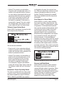
on both lamps. Pin 2 of the header is connected to the other contact on both lamps.
Pin 3 is connected, by means of a current
limiting resistor, to the external 24 volt
DC source. If lamps were obtained from
Studio Technologies then adding a “jumper” from pin 2 to pin 3 is all that is required
to get things going. A standard 0.1-inchcenter jumper, commonly used on electronic equipment, is all that is required. A
390 ohm, 1 watt resistor is electronically
in series between the external 24 volt DC
input and pin 3 of the header. When used
with the lamps available from Studio Technologies, the resistor limits the lamp current to approximately 40 mA. This lights
the lamps to a moderate intensity. If a
different type of lamp is installed, its power
source should be connected to pins 1
(common) and 2 (lamps) of the header.
Remote Control Connections
Provision has been made on the Model
210’s printed circuit board assembly to
allow external switches or contact closures
to control the main output and talkback
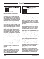
output functions. A 3-position header,
labeled P14, provides access to the circuitry associated with the functions. Pin 1
of the header is connected to the common
point of the Model 210’s circuitry. Pin 2 of
the header is connected to the circuitry
associated with main output pushbutton.
Pin 3 of the header is connected to the circuitry associated with the talkback output
pushbutton. The input circuitry is “active
low,” with a 10 k ohm resistor connected
to +5 volts acting as a pull up. A combination of resistors and capacitors provide
ESD protection. A qualified technician can
use these inputs for special applications.
Contact the factory for additional details.
Model 210 User Guide
Studio Technologies, Inc.
Compressor Circuit
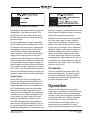
In this section some general information
about the Model 210’s compressor
circuit will be provided. As previously
discussed, the output of the microphone
preamplifier circuit is connected to a
studio-quality compressor circuit. The output of the compressor is used by the talkback output and, if configured, the main
output. (In most cases the main output
will utilize the signal coming directly out
of the microphone preamplifier.) The gain
element in the compressor circuit is a
laser-trimmed voltage-controlledamplifier integrated circuit. It provides
accurate, low-noise, low-distortion performance. The threshold of the compressor circuit is 2 dB above the Model 210’s
nominal internal operating level of –2 dBu.
A 5:1 compression ratio is implemented
and, like the threshold level, is not field
adjustable. The threshold and ratio settings were selected so that excellent
talkback audio would be provided. By
controlling the dynamic range, intelligibility
can be improved and overloading of connected devices can be avoided. An LED
indicator lights whenever the compressor’s threshold has been reached and the
circuit is actively controlling the dynamic
range. This LED is provided as an aid
when setting the gain of the microphone
preamplifier.
Issue 4, October 2008
Page 33