1
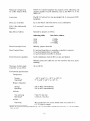
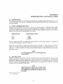
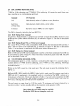
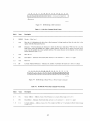
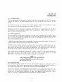
Table 4-1
CSR Word Format (Cont)
Bit(s)
Name
Description
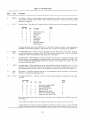
10-13
EO-E3
Data late indicates that the FI FO RAM was more than half full and the controller was not able to read the
next sequential sector. This error may occur during a Read Without Header Check command.
Header not found indicates that an OPI timeout occurred while the controller was searching for the correct sector to read or write. A header compare did not occur.
A nonexistent memory error indicates that during a DMA transfer the memory location addressed did not
respond with RPL Y within lOlls.
A memory parity error abort indicates that a parity error was detected while reading the system's optional
memory that has parity error checking. I f an error was detected, the current command to the RL Vi 2 is
aborted.
14
DE
Drive Error - This bit is buffered from the drive error interface line. When set, it indicates that the selected drive has flagged an error, the source of which can be determined by executing a Get Status command. DE will not set ERR (bit 15) or CRDY (bit 7) until the usual occurrence of CRDY.
15
ERR
Composite Error - When set, this bit indicates that one or more of the error bits (bits 10-14) are set.
When an error occurs, the current operation terminates and an interrupt routine is started if the interrupt
enable bit (bit 6 of the CSR) is set.
Aii error bits are cleared by initializing the bus by starting a new command, with the exception of DE and
ERR if they were caused by a drive error.
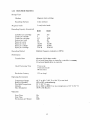
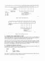
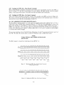
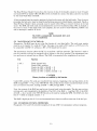
15
ERR
~~
14
13
12
11
10
09
08
07
06
05
04
03
02
01
00
D
OPI
DE NXM DLT
eRe 0
H OPI
PAR
HNF
eRe 1
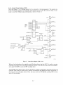
ERR
_ _ _ _ _ _ _ _ _ _, ,________AA_________________, ,_ _ _ _ _ _ _ _ _ _ _ _ _~
READ ONLY
READMIRITE
READ
ONLY
MR·5751
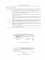
Figure 4-1
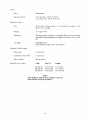
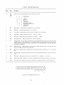
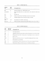
12
BA14
11
10
Control/Status Register (CSR)
09
08
07
06
05
04
03
02
01
00
BA10
\~------------------------~,,--------------------------~)
READIWRITE
Figure 4-2
Bus Address Register (BAR)
4-3
MR 5752