1
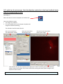
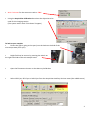
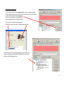
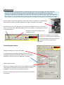
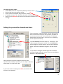
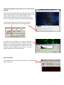
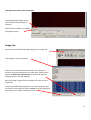
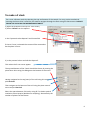
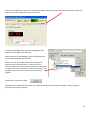
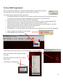
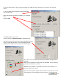
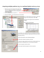
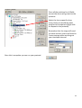
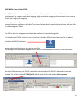
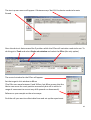
OPERATING
INSTRUCTIONS
Spinning disk
!
You must not operate this equipment without prior training from a
BALM facility staff member.
To arrange training and for help please contact:
Facility Manager
Dr Ann Wheeler
ext: 2406
[email protected]
Microscopy Technologist
Isma Ali
ext: 2407
[email protected]
Standard Operating Procedure
How to turn the equipment on:
•
•
•
•
•
Switch on the three switches (A – Mercury halide lamp, B and C left hand side on wall)
Switch on the computer and login
Wait 5 minutes for all of the equipment to initialise
Clean the objective lens you want to use
Open the software by hitting Andor Technology icon
How to turn the equipment off:
Follow the instructions beside the microscope to switch off the argon laser (allowing time for it to cool), the
computer, the microscope and the metal halide lamp
Rules of use:
This microscope should be treated with respect and care at all times. The SOP must be followed
This Microscope can only be used by Masters by Research or PhD students, Postdocs and members of staff.
The microscope lenses must be cleaned after every usage and the equipment treated carefully at all times.
If you have any problems at all with the microscope, no matter how trivial they may seem please see a
member of facility staff immediately.
•
Please ensure all sharps and clinical waste are disposed of in the sharps bin and clinical waste
bin provided.
REMEMBER:. Check before you start if you have room for your experiment. If not, delete your old data.
1
1) To switch on the microscope. Note the objective needs to be in the focus feedback device
older to be high enough to focus
Switching on
Select the IQ2 icon on the computer to initialise IQ2
Once the software is open
• The stage may initialise
• Put your sample on the microscope only when the
stage has finished initialising
The software interface looks like this
Here you control how
The experiment is done
Here you control the
Microscope itself
This menu is the one which
Shows your image
This number tells you the intensity of the pixel your mouse is hovering over (indicated by a
white arrow on the image). This can be useful when setting the lawer power and gain and
exposure of the camera .
If you want to use the focus feedback controller (PiFoc) see Appendix A at the back of the manual
2
•
Wait 5 minutes for the camera to cool to -70oC
•
Using the Acquisition Calibration box select the objective to be
used for this imaging session
(The system won’t work if this doesn’t happen)
To look at your samples
•
Ensure the light is going to the eyes (turn the knob on the RHS of the
microscope away from you).
•
Bright field can be turn on by pressing the switch on
the right hand side of the microscope stand.
•
Open the fluorescent shutter on the Mercury halide box
•
Select GFP-Eyes, RFP-Eyes or DAPI-Eyes from the Acquisition Auxillary Devices menu (the middle menu)
3
Getting Started
First of all select the protocol for your experiment
The easiest way is to choose Protocol from the menu
in the left hand side dialogue
(You can also go to protocols
Using Wizards and Protocols)
A list of protocols will appear.
Pick the one you want and press Select
The protocol for the imaging experiment you
are carrying out will then appear in the left
hand side dialogue box.
4
Taking an movie
The spinning disk is a hybrid between a wide-field epi fluorescent microscope and a point scanning
confocal. The disk itself makes the points of confocal light so the scan speed doesn’t need to be
controlled. Acquisition is controlled very much in the same way as in Metamorph, so gain and exposure
are the same. It is also possible to frame average and to change the laser power to improve your image
Send the light to the camera (Knob on right hand side of microscope turn towards you
until it click into place, turn back slightly so the light is centred in the camera.
Once you have seen your specimen you change the dropdown menu to select your
laser, for instance CSU-488-Quad. Make sure to set the light so it's going to the camera
on the microscope.
Hit Live to visualise the image on the
computer screen.
To save your settings for each channel
click 'Record'. Each time you change any
of the acquisition parameters you need
to record it or the machine won’t
remember.
Controlling the camera:
Change the EM gain (no more than 300)
For a nice picture use frame averaging, the amount of
averaging needed varies between samples so you need to
optimise it yourself. Ensure the 'Use' box is checked
Change Exposure time
NB for live imaging ensure that the time needed to acquire and
image (which is the exposure time X the number of frames
averaged) is less than the rate of data acquisition.
Ensure you hit Record at the end so the software remembers
the settings
5
To change the laser power
• Select AOTF from the 'Acquisition/Auxiliary' Devices menu
• Click on the laser you want to change
• A pop out box will appear. Adjust the laser power
• As a guide the lasers nm should be between 15-30% power
• Ensure you hit Record at the end so the software remembers the
settings
Editing the protocol for channels and time
There are general ‘protocols’ which you can edit for your
work. You can also make your own protocol provided it is
in your own user area (i.e. not in the Ann or Timelapse
setting which everyone uses – this is so it isn’t confusing
for less experienced users).
1. Set the Interval of the time-lapse (i.e. frame rate). This
is done by right clicking the interval icon and editing the
interval length in the pop out box. You put the number of
repeats and interval between images in the edit repeat
box.
2. If you wish to change a channel right click in the box
and select change Channel', you can also insert and delete
elements in the protocol here.
Once you have set up the acquisition channels and
optimised the timelaspe protocol you are ready to Run the
experiment. To do this press Run.
If you have made a mistake press STOP, correct the error
and re-run the protocol.
6
Changing the brightness and contrast on the camera during
imaging.
With Fluorescent proteins which are easily bleached it can be
better to alter the part of the image histogram shown on the
camera while imaging. This way the laser power and
exposure time can be kept low. But you can still see and
focus on your image. It works like autoscale in Metamorph.
To optimise the Brightness and contrast press manual
control which is at the bottom of the image window
A dialogue box controlling the image histograms
appears. Left clicking allows you to adjust the offset
(black point) and right clicking allows adjustment of the
maximum intensity displayed. This doesn’t alter the
raw data in your image just what you see. It can be
helpful to adjust this for dimmer samples
SAVE YOUR DATA
To save data click on the file menu (top left) in the image itself and
choose save as tif.
7
Looking at your movie after acquisition
The Wavelength dialogue allows
you to switch off the display of
channels
The Time menu allows you to play
through the movie
Image List:
Once you have finished collecting data go to the Image List
The Image list menu will appear.
This has a list that has been autosaved in the computer’s
memory of all the experiments you have done. Please select
these and delete the experiments carried out during your
imaging session from the image list.
NB If the image list gets full the machine will crash so this is
important!
If you have accidentally forgotten to save an experiment you
can find it in the image list and click show. This will reload your
experiment. You will then be able to save it.
8
To make a Z stack
The z-scan software works by selecting the top and bottom of the sample. For very precise mechanical
scanning the Piezo drive is used. So you need to navigate through the stack using the Piezo motor. DO NOT
TOUCH THE FOCUS ON THE MICROSCOPE STAND!!!
1) Open the protocols menu (as for Time series)
2) Select Z Stack from the options.
In the Z protocol select Repeat Z and choose Edit
If Centre Z scan is selected the centre will be assumed to
be the plane in focus.
3) In the protocol select and edit the Repeat Z.
This makes the Z scan menu appear.
The top and bottom of the Z stack should be chosen by moving the
piezo focus drive using the dialogue at the bottom of the menu.
Having navigated to the top (start) of the cell using this menu
pick Set Start
Then navigate to the bottom of the cell using the piezo control
menu and pick Set End
Select the space between Z slices by using dZ. To obtain optimal
resolution select Nyquist (double over sampling). Alternatively the
number of planes can be chosen
9
If there is a problem with the piezo Z drive and it needs resetting picking the Piezo Menu option. Refocus to
where you need manually and reset in the menu.
Piezo
Z stacks can be added into a protocol by adding a time
repeat into the (Right click and edit).
More channels can be added by right clicking below the
Frame option and adding a channel.
Ensure that the End Z item is after the new channel
otherwise the software will do a z stack of the first
channel and either not one of the second. Or alternatively
a z stack of channel 1 and then a z stack of channel 2. The
problem then is the two channels may not correctly
register.
Choose Run to collect the data
NB Please come and ask if you need a new protocol setting up as the BALM manager is always happy to
support these type of requests.
10
To do a FRAP experiment
Select a protocol with FRAP in it. If you haven’t done FRAP for a while you will need to
do a test FRAP to ensure the laser power is still OK for your experiment.
To consider when carrying out a FRAP experiment
• The FRAPPA bleaches the sample by point scanning. It will take a short time (1 sec) for the system to
switch back to spinning disk confocal imaging please allow for this in your experiment
• For good recovery you need to bleach your dye by about 50%
• The camera noise level is set to read an intensity of around 300. In order to quantify FRAP you will
need the structure you are hoping to FRAP to have an intensity of 1000 or more.
• The FRAP doesn’t bleach a point. It bleaches the point spread function in your image, (i.e. the focal
planes above and below where you bleach will also be bleached).
• FRAPPing with too much laser power may kill your cell
• The FRAPPA can only bleach shapes with upto 8 sides, it won’t FRAP a circle but can do parallelograms
1. Snap an image of the sample you want to FRAP
2. Select FRAPPA from the ROI menu.
Draw the ROI you are interested in on your image (NB no more than 8 sides)
Select the FRAPPA Channel by right clicking in
the image
Select the FRAP laser you want (Tick appears
next to laser)
To test FRAP click FRAPPA this
11
If the Test FRAP doesn’t work it will be necessary to modify the FRAP settings. This is done in the Channels
menu
In the Left hand menu box select Channel Manager
from the Wizards
Select the Channel you want to modify (i.e. a FRAPPA
one)
And click Edit
Click Next twice in the menu
You are now at the Bleach settings for FRAPPA menu
Here you can control the Bleach settings. Modify the dwell
time (i.e. how long the laser is on the sample) and the
Repeats (how many times the laser visits the sample).
Click Next three times until you arrive at the AOTF settings for the
FRAPPA.
Here you can modify the laser power for the FRAP. Ensure the laser
you want to FRAP with is ticked.
NB Make sure FRAPPA is selected in the menu at the bottom. If it
isn’t your FRAP won’t work!
Once this is completed repeat the test FRAP. If its ok you can run the
FRAP protocol as you would any other protocol
12
Acquiring multiple positions (e.g. in a multiwell plate) can be xy or xyz
1. Make sure you have registered the stage if not
lower the objective so it doesn't crash into the
stage. Go to Wizards in the menu and choose
Stage Registration.
2. Select a Protocol with a xy scan in it
3. Select the Repeat - XY in the protocol and choose Edit
The XY wizard will ask if you want to move the
stage to the stored position. Select No
(otherwise the stage will move somewhere
random)
The XY scan map will appear
It is possible now to either select a pre-recorded scan and use
these xy settings or edit them. (Please don’t edit the 12 and 24
well plate presets)
To edit the positions use the following dialogue.
1. Select the number of positions you want
2. Move the stage using the joystick to the x and y position you
want (this is recorded in the x, y and z position window)
3. Focus using the Z position menu
4. Press Next Field and repeat for the next position
13
Once all the positions for all fields
are set the menu will go back to the
protocol.
Select the time repeat for how
many times you would like each
position to be acquired. (Right click
on Repeat in the protocol).
Remember that the stage will need
to move and the system will need to
Frame average when working out
your timelapse interval.
Once this is complete you can run your protocol.
14
APPENDIX A Use of the PiFOC
The PiFOC is a focus correcting device. It is useful for applications where drift in the z axis is
anticipated. E.g. super-resolution imaging, high resolution imaging of structures in the centre
of the cell, long term imaging.
Do not have the cell you want to image in focus before you start this process as it may bleach.
Instead choose a region or cell which you aren’t interested in acquiring data from and use this
for calibrating the Z axis.
The PiFoc doesn’t integrate into the Andor software it works alongside it.
To initialise the PiFOC, switch it on on the box. Initialise IQ2 first and wait until it is loaded.
Initialise the PiFOC software
Agree when it asks whether to run the exe file.
The dialogue box below will appear. Press Start to automatically connect to the controller.
One the PiMicromove, the PiFOC controller has initialised the PiFOC will need to be auto
Zeroed. To do this choose E-753(Com7) which is the PiFoc and select Start up axes
15
The start up axes menu will appear. If Autozero says ‘Not Ok’ the device needs to be auto
Zeroed
Once the device is Auto-zeroed the Z position which the PiFoc will maintain needs to be set. To
do this got to Tools and select Single axis window and select the PiFoc (the only option)
The control window for the PiFoc will appear.
Set the target in this window to 80um
(The Pifoc can move between 0 and 100um, but 80um means that the
device can sense the z axis position accuractely but still is within its
range of movement to correct any drift upwards or downwards).
Refocus on your sample on the microscope.
Find the cell you want to collect data from and set up the experiment.
16