1
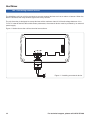
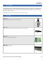
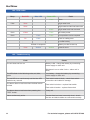
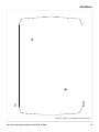
Pump Station High Level Alarm
AlertMaxx
Installation & Operating Instructions
For Ground Water (DMS - 270) and Foul Water (DMS - 269)
T.
01992 523532
[email protected]
W.www.deltamembranes.com
AlertMaxx
AlertMaxx
Contents
1.0
AlertMaxx overview
4
2.0
Box contents
4
2.1
Cardboard box contents
4
2.2
AlertMaxx unit contents
4
3.0
Technical information
5
4.0
Unit location
5
5.0
Mounting instructions
5
5.1
Mounting the AlertMaxx unit
5
6.0
Connecting mains power to the AlertMaxx unit
6
7.0
Installing the float switch in the chamber
7
7.1
Installing a finger float into a ground or surface water chamber
7
7.2
Installing a pendant float into a foul water chamber
7
8.0
Connecting the float switch to the AlertMaxx unit
9
9.0
Activating & testing the AlertMaxx unit
11
9.1
Turning on the AlertMaxx unit for the first time
11
9.2
Testing the float switch
11
9.3
Finalising the settings
11
10.0 Connecting external devices
12
11.0 Servicing
13
12.0 Spares
13
13.0 LED Codes
14
14.0 Troubleshooting
14
For technical support, please call 01279 757400
3
AlertMaxx
1.0 AlertMaxx overview
This high level alarm is designed to alert home owners when the water level in their pump chamber becomes
too high. The unit will also inform home owners when a service is due on their pump station.
2.0 Box contents
2.1
•
•
Cardboard box contents
1 x AlertMaxx Unit
1 x Installation & Operating Instructions
Groundwater version (DMS-270)
•
•
•
1 x Finger Float Switch
1 x Finger Float Housing
2 x Cable Ties
Foul Water version (DMS-269)
•
•
2.2
•
•
•
•
•
4
1 x Pendant Float Switch
1 x Cable Tie
AlertMaxx unit contents
2 x Large Cable Gland
2 x Large Blanking Plug
2 x Small Cable Gland
2 x Small Blanking Plug
1 x 6V Battery
For technical support, please call 01279 757400
AlertMaxx
3.0 Technical information
AlertMaxx Specification
Size (without cable glands)
W: 115mm x D: 95mm x H: 60mm
Weight
650g
Mains Supply
200-250V AC (50Hz)
Internal Battery
Pb 6V - 1.2Ah
Alarm Sound Level
81db
Visual Display
Red, Blue, Green LED
4.0 Unit location
The AlertMaxx must be positioned in an area where the alarm can be clearly heard and is permanently
accessible.
PLEASE NOTE - The AlertMaxx unit is not waterproof and must be installed indoors or
inside a kiosk.
5.0 Mounting instructions
5.1
1.
2.
3.
4.
Mounting the AlertMaxx unit
Using the template provided on page 15 of this instruction manual (figure 1), mark the fixing positions on the wall.
Drill the two holes and fit suitable wall plugs (ensure correct wall plugs are used for the wall type).
Remove the screws from the front of the unit that secure the front fascia.
Secure the AlertMaxx unit to the wall using appropriate screws.
CAUTION! - When securing the unit to the wall, avoid over tightening the screws as this may
cause the box to crack.
For technical support, please call 01279 757400
5
AlertMaxx
6.0 Connecting mains power to the AlertMaxx unit
1. Replace the far right blanking plug (large) with a large cable gland.
2. Feed the mains power cable through the right hand cable gland (large) and connect the power cable to the terminal strip (see figure 2).
CAUTION! - Ensure mains power is isolated before connecting it to the AlertMaxx unit and seek
advice from a qualified electrician.
LNE
Figure 2. Connecting mains
7.0 Installing the float switch in the chamber
Care must be taken to ensure the correct type of float switch is installed into the chamber. Figures 3 & 4
show the two float switch options.
7.1
Installing a finger float into a ground or surface water chamber
1.
2.
Using the nut and washer provided, secure the finger float to the inside of the float housing so that the float rises with rising water levels (see figure 5).
Using the two cable ties provided, attach the float housing to the discharge arm so it is 300mm from the base of the chamber (see figure 6).
6
For technical support, please call 01279 757400
AlertMaxx
7.0 Installing the float switch in the chamber
7.2
Installing a pendant float into a foul water chamber
Option 1 - Free standing foul pump
1. Using the cable tie provided, attach the float cable to the discharge arm allowing the bottom of the float switch to hang approximately 350mm above the base of the chamber (see figure 7).
Option 2 - Guide rail mounted foul pump
1.
2.
3.
Pull the float cable through the float weight.
Using a cable tie, secure the float weight to the float cable so there is 80mm of float cable between the top of the float switch and the bottom of the float weight.
Drill a hole through the float bracket. Hang the pendant float from the float bracket so the bottom of the float switch hangs approximately 400mm from the base of the chamber. Once the pendant float is at the correct height, secure the float cable to the float bracket using a cable tie.
PLEASE NOTE - The pendant float switch should be located in a position where the float can
pivot with rising water levels and not become obstructed (see figure 8).
Figure 3. Finger float switch
Figure 4. Pendant float
Suitable for ground & surface water
For technical support, please call 01279 757400
Suitable for foul water
LNE
7
CK
AlertMaxx
7.0 Installing the float switch in the chamber
300mm
120
80
8
Figure 5. Ground Water Float Switch
Figure 6. Ground Water Sump (DMS - 164)
Figure 8. Foul Water Float Switch
Figure 7. Foul Water Sump (DMS - 165)
LNE
For technical support, please call 01279 757400
50
AlertMaxx
70
8.0 Connecting the float switch to the AlertMaxx unit
Using a draw cord, pull the float cable through the cable duct.
Pull the float cable through the cable gland on the AlertMaxx unit. When using the finger switch (figure 3), use the small cable gland. When using the pendant float switch (figure 4), use the large cable gland.
Connect the float switch cable to the terminal strip. When using the finger float (figure 3), connect the blue and a brown cable, (see figure 9). When using the pendant float switch (figure 4), connect the blue and black cable to the alarm box (see figure 10). The BROWN cable should be disregarded and isolated.
20
1.
2.
3.
PLEASE NOTE - If the cable supplied with the float switch is too short, the cable can be extended
using a cable with a minimum core cross sectional area of 1mm².
BLACK
BROWN
Figure 9. Wiring a finger float switch
For technical support, please call 01279 757400
9
AlertMaxx
8.0 Connecting the float switch to the AlertMaxx unit
BLACK
BLUE
Figure 10. Wiring a pendant float switch
10
For technical support, please call 01279 757400
AlertMaxx
9.0 Activating & testing the AlertMaxx unit
Before going through the testing process, ensure the mains power to the AlertMaxx unit is switched off.
9.1
1.
2.
3.
4.
5.
9.2
1.
2.
3.
9.3
Turning on the AlertMaxx unit for the first time
Remove the battery from the AlertMaxx unit and connect the red and black leads to the battery, red to red and black to black.
Re-secure the battery to the unit by pressing the Velcro on the battery hard against the Velcro on the unit until a ‘click’ is heard.
Once the battery has been connected, the alarm will beep three times and all three LEDs will flash three times.
Check that the green LED flashes every second and after one minute the unit emits a short beep followed by a flash from the red LED every 5 seconds.
Turn on the mains power supply to the AlertMaxx unit. The beep and red flash from step 4 will stop after approximately 30 seconds.
Testing the float switch
Test the alarm by pressing and holding the ‘TEST’ button for ten seconds. The alarm will sound and the red LED will flash every second.
Release the ‘TEST’ button. The alarm and flash from the red LED will stop within 10 seconds.
Test the float switch by raising the float switch to its upright position. The alarm will activate within 10 seconds.
Finalising the settings
1. Press the ‘RESET’ button to reset the unit.
2. The activation & testing is now complete and the AlertMaxx unit is ready for use.
For technical support, please call 01279 757400
11
AlertMaxx
10.0 Connecting external devices
The AlertMaxx unit has volt free contacts to connect external devices such as an alarm or beacon. When the
alarm is activated the relay sends a signal once every second.
The volt free relay is designed to accept devices with a maximum load of 0.5A and voltage between +6 to
7V DC. If external devices fall outside these parameters, the external device must be powered by an external
power supply.
Figure 11 below shows the volt free terminal connections.
Figure 11. Installing an external device
12
For technical support, please call 01279 757400
AlertMaxx
11.0Servicing
The AlertMaxx unit will alert home owners when their pump station requires servicing. This is indicated by
the blue LED flashing every second followed by one beep every minute. The beep can be muted by pressing
the ‘RESET’ button. However, the beep will return 7 days from pressing the ‘RESET’ button until a service
technician resets the alarm unit.
The AlertMaxx unit has a factory default service interval of 12 months.
12.0Spares
120
40
80
20
70
50
DMS - 194
Float Switch type BR10 for foul water applications
120
40
80
50
DMS - 276
Broken finger float switch for ground and surface water applications
BLACK
BROWN
20
70
LNE
DMS - 277
Shroud for broken finger float switch
BLACK
BROWN
DMS - 275
Rechargeable 6v battery
For technical support, please call 01279 757400
13
AlertMaxx
13.0 LED codes
Beep
Red LED
Blue LED
Green LED
1/sec
3/sec
High water level
3/sec
High water level but has been reset
1/sec
1/min
1/5sec
1/min
1/sec
On
Fault
None
2/sec
High water level has occurred
1/sec
No mains power
1/sec
Pump station service required
1/sec
Float or cabling error
Low/flat battery
All flash in sequence
1/sec
Various
Battery too flat to start up
Various
Internal errors
14.0Troubleshooting
Fault
The unit does not turn on
Cause
Battery is flat - charge the battery by connecting
mains supply to alarm unit
Still doesn’t turn on after 3 mins - alarm unit is
faulty
The LEDs flash in the following order, red, blue,
green
Low battery - charge the battery by connecting
mains supply to alarm unit
The red LED is on continuously and the blue LED
flashes every second
Float switch cable is faulty - check float switch connections and cable for damage
The alarm does not activate when the float switch
is lifted
Float switch is broken - replace float switch
Float cable is broken - replace float switch
The alarm does not activate when pressing the
‘TEST’ button.
Faulty unit
Alarm continuously active
Pendant float has been incorrectly wired - check
the blue and black cables are connected correctly
14
For technical support, please call 01279 757400
Bottom
Top
AlertMaxx
Figure 1. (Scale 1:1) Mounting hole positions
For technical support, please call 01279 757400
15
T.
01279 757400
W.www.ppsgroupuk.com
After Sales Service
All Delta Membrane Pump Systems are fitted and can be maintained by our partners Packaged Pump
Systems. With our long-term relationship we ensure that the system selected is fit for your requirements,
is delivered on time, professionally fitted and offers hassle free on-going operation and maintenance.
PPS - Precise, Passionate Service
Precise
Fully trained in-house service engineers to maintain, enhance and replace equipment.
Passionate
Bespoke design, manufacturing and installation ensuring our equipment is fit for every requirement.
Service
From fitting to scheduled maintenance they ensure your needs come first.
•
•
•
•
•
Fully stocked vans
Emergency breakdown service
Out of hours service
Planned maintenance
Factory trained engineers
T.
01992 523532
[email protected]
W.www.deltamembranes.com
Delta House, Merlin Way, North Weald, Epping, Essex CM16 6HR