1
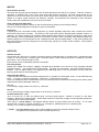
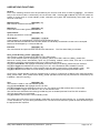
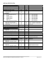
Fire Control Panel
Installation & Programming Manual
TABLE OF CONTENTS
Getting Started
Power Supply Unit
Remote Keypad Bus
Inputs & Outputs
User Keypad Functions
Engineer Keypad Functions
Troubleshooting
Specification
LED Indications
Connection Diagram
Keypad Function Chart
Noby-448 Installation & Programming Instructions
(Rev.5)
Page
2
3
3
4
5
6
7
9
10
11
12
Page 1 of 12
GETTING STARTED
We strongly recommend that the Noby-448 is first powered up with all 4K7 End Of Line resistors fitted at the panel
as supplied by the factory. In this way you can gain confidence that the panel is operating correctly before
introducing detector and sounder circuits.
Power-Up With Battery
• Connect two 12v SLA batteries in series (+’ve to –‘ve) to form a 24 volt battery stack, using the
battery jumper link supplied.
• Connect the black battery lead to the battery stack –‘ve terminal.
• Connect the red battery lead to the battery stack +’ve terminal. It is normal to see a small spark.
• The Common Fault LED will be continuously lit together with flashing PSU and CPU fault LEDs.
These faults are also accompanied by an audible fault tone signified by 4 rapid pips every 4 seconds.
• Press [3][6][3][6] [1][4][5] to silence and perform a System Reset – observe 3 second LED test.
• The panel should then settle to quiescent state with all LEDs off.
• Connect the mains power supply to the fused screw terminal block
• The panel should now be in a standby state with only the green Power LED continuosly lit.
Power-Up With Mains
• Connect the mains power supply to the fused screw terminal block.
The green Power LED will be continuously lit.
The Common Fault LED will be continuously lit together with flashing PSU and CPU fault LEDs.
These faults are also accompanied by an audible fault tone signified by 4 rapid pips every 4 seconds.
• Connect two 12v SLA batteries in series (+’ve to –‘ve) to form a 24 volt battery stack, using the
battery jumper link supplied.
• Connect the black battery lead to the battery stack –‘ve terminal.
• Connect the red battery lead to the battery stack +’ve terminal. It is normal to see a small spark.
• Press [3][6][3][6] [1][4][5] to silence and perform a System Reset – observe 3 second LED test.
• The panel should now be in a standby state with only the green Power LED continuosly lit.
Notes
1. The panel will persist in reporting a PSU fault after a System Reset if the battery is either not present or the
battery fuse F7 has blown.
2. Whilst there is a measure of protection against accidental reverse connection of the battery, such action will
blow fuse F7 and may cause permanent damage to the panel.
Installing the Noby-448XT 4-Zone Extender Card (Optional)
• Disconnect the mains & battery power supplies prior to fitting the Noby-448XT.
IMPORTANT: Failure to heed this warning may damage the circuitry.
• Install the Noby-448XT into the cabinet using the 3 mounting pillars supplied.
• Connect the Noby-448XT to the Noby-448 Main PCB using the 10-way ribbon cable.
• All zone and sounder circuits must be terminated with a 4K7 EOL resistor (supplied).
• Restore the mains and battery power supplies to the panel.
• FINALLY . . . you must configure the panel software to recognise the Noby-448XT:
o Key [6][2][5][3] [3][5] to enter programming mode.
o Key [1] to Toggle the option - the yellow zone fault LED’s display the active zones.
o Key [4] to Accept and update the configuration option to E2PROM memory.
o Key [5] to Quit and revert back to normal standby mode without updating the E2PROM.
Noby-448 Installation & Programming Instructions
(Rev.5)
Page 2 of 12
POWER SUPPLY
The PSU comprises two high-efficiency regulators providing voltage rails of 27.3v and 13.6v (nominal 24v and 12v
respectively), with a combined continuous current rating of 2.0A, and a 20 minute rating of 2.5A. The PSU is
designed to meet the internal standby power requirements of the Noby-448 and also to charge and maintain the
SLA standby battery in optimum condition. The battery standby time is dependant upon the overall system current
drawn, including any ancillary equipment connected to the Aux 24v and Aux 12v terminals. Also it is strongly
recommended that the continuous system standby current does not exceed 1.5A, because some ‘reserve’ PSU
current may at times be required to rapidly re-charge the battery (e.g. after an alarm condition or prolonged period
of mains loss).
The Noby-448 enclosure can accommodate two 12v/7Ahr SLAs connected in series. The PSU is capable of
handling batteries up to 12Ahr, but these larger batteries must of course be housed in a separate enclosure. Care
must be taken when planning an installation that there is sufficient battery capacity to meet the relevant standards
regarding battery standby times.
Always ensure that the maximum current drawn in alarm does not exceed the 3.0A battery fuse limit (F7).
The PSU is monitored for :
i)
Mains Absence
ii)
Low Voltage < 21v
iv)
iii)
v)
vi)
Battery Capacity Test
Fuse F7 (Battery/Low Volts)
Fuse F1 (Remote/Aux 12v)
Fuse F2 (Aux-24v)
Power LED extinguishes when mains absent for more than 90
seconds and flashes once mains restored. Mains absence is
accompanied by an intermittent warning bleep every 16s
(mutable).
PSU Fault LED continuously lit whilst voltage < 21v and flashes
when voltage is restored to > 23v
PSU Fault LED flashes
PSU Fault LED flashes
PSU Fault LED flashes
PSU Fault LED flashes
Note 1: PSU faults are accompanied by a fault tone signified by 4 rapid pips every 4 seconds.
Note 2: The Battery Capacity Test is performed immediately after a System Reset and thereafter at 12 hour
intervals.
REMOTE KEYPAD BUS
Up to three external Noby-448RKP remote keypads can be connected to the remote serial bus.
Ensure correct connectivity A to A and B to B.
Each Noby-448RKP must be set to a unique dip-switch address in the range 2 to 4 (the factory setting is address
2). Note that address 1 is reserved for the internal lid mounted keypad on the Noby-448.
Take care when installing a 3rd or 4th keypad to adjust the address switch to 3 or 4.
Note that the system is tolerant of address gaps i.e. it is OK to have addresses 1,2 and 4, but address conflicts
will give rise to spurious keystroke entry.
The bus address configuration is registered at first power-up and again every time the panel is reset.
Any loss of communication is indicated by a continuously lit CPU Fault LED, together with an audible fault warning
from any remaining functional keypads. There is also a 'backup' piezo sounder on the main PCB to draw attention
to a bus fault. In the event of complete remote bus failure the panel will fail safe and continue to operate as a fire
detection system, albeit without the means to silence it. The fuse F1 supplying the Remote Bus is monitored and
will generate a simultaneous PSU Fault and CPU Fault condition if it should blow.
The maximum cable length is largely determined by the type of cable employed and the installation environment.
The remote keypads can be wired and distributed along the cable in any configuration provided the total cable
length connected does not exceed 500m.
Important: the main precaution is to minimise the volt drop along the 12v and 0v supply cores by using thicker wire
or doubling up the spare cores. In normal standby, with only the Power LED lit, the terminal voltage at each remote
should be 12v or higher (as compared to approx.13.6v at the panel terminals). When troubleshooting, a good rule
of thumb is that the voltage at the remote keypads must not drop below 10v at maximum current draw during the 3
second reset period - i.e. this is the maximum current draw when all LEDs are lit.
Failure to heed this warning may give rise to intermittent and/or unreliable remote keypad operation.
Noby-448 Installation & Programming Instructions
(Rev.5)
Page 3 of 12
INPUTS
Zone Detector Circuits
The Noby-448 requires that each detector zone is terminated with a 4k7 End Of Line resistor. This EOL resistor is
necessary to facilitate open circuit, short circuit and head removal monitoring. The total current drawn by the
detectors on each circuit must not exceed 2mA, which means that 20 detectors can be connected to each zone
(based on a typical 100uA maximum per detector). Similarly, if the detectors are specified at 50uA maximum
current draw, then 40 detectors per zone can be connected.
Class Change Input (Bell Ring)
A positive going input signal to switch on the sounders directly (subject to their isolation status).
The input is non-latching and no indication is given on the display.
Fault Input
A signal input from connected ancillary equipment eg. remote signalling equipment, which causes the Common
Fault LED to flash when activated. The polarity of the Fault_Input signal is programmable (software version 1-8
onwards). The factory setting is for a positive voltage-applied, which requires no external connection to hold off the
fault indication, which is preferrable if the input is not used. However, when connecting a fault signal fed back from
remote equipment it is recommended to use a voltage-removed signal for added safety. In this case the Noby-448
fault input polarity should be configured to be normally high, going low to initiate a fault condition. See Engineer
Keypad Functions.
OUTPUTS
Sounder Circuits
Conventional 4k7 End Of Line resistor monitoring requiring polarised bells or sounders with a combined output
current of 1.25A across the 4 sounder ports. The Noby-448XT 4-Zone Extender provides an additional 4 sounder
ports with a 1.25A combined output current.
Each sounder circuit is individually fused and monitored.
Fire Relay Output
Double pole voltage free contacts, 1A@30V, activated upon detection of a zone fire or by the keypad operated
Evacuate function. It is latched until a System Reset. The relay can be isolated - see User Keypad Functions /
Isolation. The Fire Relay Output is not triggered by the Bell Ring Input or from any activation of a zone that has
been programmed as a non-latching zone.
Panel Sounder (Piezo)
A piezo sounder is located at each Remote Keypad Unit to provide for local keypad ‘clicks’, fire and fault warning
tones. Fire tone = continuous rapid pips. Fault tone = 4 rapid pips every 4 secs.
There is an additional piezo sounder fitted to the main PCB to provide an audible fault warning in the unlikely event
of Remote Bus failure (damaged cable etc.).
Aux 12v
A 12v auxiliary supply fused at 1A (Fuse F1), monitored.
Aux 24v
A 27.3v (nominal 24v) auxiliary supply fused at 1A (Fuse F2), monitored.
Communication Port (JP1)
JP1/1 to JP1/8 (“Z1” to “Z8”) are positive going 12v/10mA signal outputs, latched on receipt of a fire alarm
condition, cleared upon System Reset. These signal outputs are sufficient to trigger remote signalling equipment,
or perhaps drive a mimic LED display.
JP1/9 (“Flt”) is a Fault Output ** and signals real-time status of System Faults from all sources. It is an open
collector PNP 12v/50mA, normally switched to 12v, switched off (released) if there is a standing fault.
JP1/10 (“0”) is 0 volts or system common ground.
** NOTE: The Fault Output signal is also made available on the screw terminal marked “FAULT”.
This applies to circuit board PC146-3 onwards (Revision 3).
Noby-448 Installation & Programming Instructions
(Rev.5)
Page 4 of 12
USER KEYPAD FUNCTIONS
General
Each of the following functions must be preceded by the Access Code which is fixed at [3][6][3][6]. Successful
entry of the Access Code is confirmed by the red Function LED. Pressing [5] to Quit at any time will cause the
system to revert back to normal standby mode, otherwise the system will automatically revert back after 10
seconds of inactivity.
Mute Sounders
[3][6][3][6] [1]
Main external sounders switched off.
Mute Panel
[3][6][3][6] [4]
Panel internal sounders (piezos) switched off.
System Reset
[3][6][3][6] [5]
All LEDs are tested for 3 seconds.
Quick Reset
[3][6][3][6] [1] [4] [5]
A Quick Reset is an amalgamation of the first three operations above.
Note that the Main Sounders & Panel Sounder MUST be individually muted before a reset can be accepted.
Reset is acknowledged by a 3 second LED test.
Evacuate
[3][6][3][6] [2]
The main external and panel internal sounders are switched on. The Fire Alarm Relay is activated.
Zone_Isolate & Relay_Isolate [3][6][3][6] [3]
This function is used to Isolate zones and/or the Fire Alarm Relay.
The current isolation status is displayed by any flashing yellow zone LED’s and/or the Relay_Isolate LED.
Note that scrolling down automatically wipes any pre-existing isolation status LEDs, and that it is therefore
advisable to check the whole isolation suite prior to exiting this procedure.
Key [1] to Scroll-Down and highlight the desired yellow zone LED (or the Relay_Isolate LED) for selection.
Key [3] to Toggle the selected zone (or the relay) on or off – the LED flashes when isolatation is active.
Key [4] to Accept and update the current isolation status and then revert back to normal standby mode . . .OR
Key [5] to Quit and revert back to normal standby mode without updating the displayed isolation status.
Once back in normal standby mode any isolated zone (or relay) is confirmed by a flashing zone fault LED (and/or
Relay_Isolate LED). Zone_Isolate and/or Relay_Isolate operations should only be performed or authorised by the
Installation / Service Company).
Test
[3][6][3][6] [6]
This function is used to ‘one-man’ test the system.
Key [1] to Scroll-Down and highlight the zone for test.
Key [6] to Toggle the zone selected for test on or off – the yellow zone LED will flash when in test mode.
It is now possible to trigger each detector in turn on the selected zone.
The sounders are activated momentarily (provided they are not isolated) and the Zone Fire LED is latched.
The Fire Alarm Relay is not activated.
Key [5] to Quit to revert back to normal standby mode.
The system will revert back to normal standby mode after 90 seconds of panel inactivity (i.e. no keypad operations
or zone activations). Any fire alarm generated from a non-test zone will cause the system to abort the test and give
the appropriate fire response.
Noby-448 Installation & Programming Instructions
(Rev.5)
Page 5 of 12
ENGINEER KEYPAD FUNCTIONS
General
Pressing [5] to Quit at any time will cause the system to revert back to normal standby mode, otherwise the system
will automatically revert back (kickback) after 10 seconds of inactivity.
Isolate Sounders
[6][2][5][3] [3][1]
This function is used to isolate the main sounders. The panel piezo sounder is unaffected.
Key [3] to Isolate the sounders - a toggle on/off action.
Key [4] to Accept and update and then revert back to normal standby mode.
Key [5] to Quit and revert back to normal standby mode without updating the Sounder Isolate status.
The sounder isolation status is confirmed by a flashing Sounder Fault LED.
8 Event Log Recall
[6][2][5][3] [6][1]
This function is used to recall and view the previous 8 fire activations.
Key [1] to Scroll Down or rather scroll back through the last 8 events - and then revert back to standby.
Key [2] to Accept, clear the log memory and then revert back to normal standby mode..
Key [5] to Quit and revert back to normal standby mode without clearing the log memory.
Note : the log records a snapshot of the zone fire LED’s at the instant the panel is Reset.
Configure Noby-448XT 4-Zone Extender
[6][2][5][3] [3][5]
This function is used to upgrade the software to recognise 8 zones.
Key [1] to Toggle the option - the zone fault LED’s display the active zones.
Key [4] to Accept and update the configuration option to E2PROM - then revert back to normal standby mode..
Key [5] to Quit and revert back to normal standby mode without updating the E2PROM.
Configure Fault_Input Polarity
[6][2][5][3] [3][5]
This option configures the Fault_Input signal to be normally high, going low to initiate a fault condition.
Key [2] to Toggle the option - the Common Fault LED indicates the current option status.
Key [4] to Accept and update the configuration option to E2PROM . . . OR
Key [5] to Quit and revert back to normal standby mode without updating the E2PROM.
The factory default is with the option disabled i.e. the Fault_Input is normally low, going high to initiate a fault
condition.
Configure Latching Zone Faults
[6][2][5][3] [3][5]
This function is used to configure latching zone faults.
Key [3] to Toggle the option - the Isolate LED displays the current option status.
Key [4] to Accept and update the configuration option to E2PROM - then revert back to normal standby mode..
Key [5] to Quit and revert back to normal standby mode without updating the E2PROM.
The factory default is with the LZF option disabled – i.e. non latching zone faults.
Weekly Test Reminder
[6][2][5][3] [3][5]
This function is used to enable / disable the Weekly Test Reminder function.
Key [6] to Toggle the option - the Test LED display the current option status.
Key [4] to Accept and update the configuration option to E2PROM - then revert back to normal standby mode..
Key [5] to Quit and revert back to normal standby mode without updating the E2PROM.
The factory default is with the WTR option disabled. Once enabled the WTR will cause the Test LED to flash
accompanied by an intermittent warning sound (mutable) after 1 week of no fire activity on the panel. The timer is
automatically reset after a fire condition has been generated and subsequently cleared (i.e. a manual test cycle).
Configure Non-Latching Zones
[6][2][5][3] [3][2]
This function is used to programme any of the 8 zones to be non-latching.
Key [1] to Scroll-Down and highlight the zone for selection.
Key [3] to Select a particular zone.
Key [4] to Accept and update the non-latching status to E2PROM and then revert back to normal operating mode.
Key [5] to Quit and revert back to normal standby mode without updating the E2PROM.
Note: A non-latching zone will momentarily activate the sounders (subject to their isolation status), panel sounder,
and also display momentary indication on the appropriate zone fire LED. Non-latching events are not logged.
Sounder Fault Identification
[6][2][5][3] [1][1]
This function is used to identify which sounder circuit is in fault condition. The sounder circuit in fault is indicated
by means of the yellow zone fault LEDs 1 thru 8.
Key [5] to Quit and revert back to normal standby mode without updating the E2PROM.
Noby-448 Installation & Programming Instructions
(Rev.5)
Page 6 of 12
TROUBLESHOOTING
Power Supply
The Power LED not illuminated?
• Check that the mains supply is connected and switched on.
• Check the fuse in the terminal block adjacent to the transformer.
• Check the fuse F8 on the main board.
PSU Fault LED continuously illuminated?
• The panel is detecting low voltage (< 21V) from the batteries.
• Check the batteries are connected correctly, in series, and observing strict polarity.
• The batteries may be heavily discharged – allow approx. 1hr for a partial re-charge.
The PSU Fault LED will flash when the battery voltage increases to 23V.
The PSU Fault will clear when the panel is reset.
• The batteries may be faulty – replace as necessary.
PSU Fault LED flashing?
• Check the batteries are connected correctly, in series, and observing strict polarity.
• Check Fuse F7 (Battery).
• Check Fuse F1 (Ext. Remote / and Aux 12V ).
• Check Fuse F2 (Aux 24V).
Zone Faults
Zone Fault LED continuously illuminated?
• Disconnect the relevant zone and replace with the EOL resistor (4K7) at the zone terminal. If the fault can
now be cleared then there is a possible wiring error in the zone.
• Check that the correct value EOL resistor is fitted at the end of the zone.
• Check that the wiring and connections at each detector are consistent, and not crossed-over at any point
along the cable run.
• Check that all manual call-points in the zone are intact and fitted with an appropriate EOL resistor, typically
470 ohms.
• If a Zone Fault LED becomes continuously illuminated when a head is removed, then that detector base may
be the wrong type. Check that a schottky diode is fitted and correctly connected.
Replace the suspect detector base if necessary.
Zone Fault LEDs Flashing?
• One or more zones are isolated.
Zone Fault LED intermittently winking?
• A detector head is either missing or incorrectly connected.
• Check all detector heads on the corresponding zone are fully seated in their bases.
Sounder Faults
Sounder Fault LED continuously illuminated?
• Enter the code [6][2][5][3][1][1] to bring up the sounder fault display, shown by the zone fault LEDs.
• Check the corresponding sounder fuses F3, F4, F5 or F6 on the main board, or fuses F1, F2, F3 or F4 on
the Noby-448XT extender board (if fitted).
• Disconnect the suspect sounder circuit and fit a 4K7 EOL resistor at the sounder terminal. If the sounder
fault clears then there is a possible wiring fault in the circuit. Check all connections between sounders.
• Check that the correct value 4K7 EOL resistor is fitted in the circuit.
Zones 5 to 8
Continuous Zone Faults And Sounder Faults?
• If the Noby-448XT module is fitted then check that the 10-way ribbon cable connector is secure.
• If the Noby-448XT module is not fitted, then ensure that the programmable option ‘Configure Noby-448XT 4Zone Extender’ is set to de-activate zones 5 to 8.
Zones 5 to 8 Don’t Work At All?
• The Noby-448XT module is not fitted, or the ribbon cable not connected.
• The programmable option ‘Configure Noby-448XT 4-Zone Extender’ is not set.
Noby-448 Installation & Programming Instructions
(Rev.5)
Page 7 of 12
CPU Fault Indication
CPU Fault LED Continuous?
• It is possible one or more display boards have had their address changed. Reset the panel to reconfigure for
the address changes.
• If there have been no address changes then one or more remotes have failed to communicate to the main
board. Check the wiring between all remotes that do not appear to be working.
CPU Fault Flashing?
• It is normal behaviour to see a CPU Fault at power-up . Clear by performing a panel reset.
• Persistent CPU faults may indicate interference from electrical machinery or RF transmitters in the locality.
Common Fault Indication
Common Fault LED Flashing persistently?
• Check that the Fault_Input polarity is correctly programmed (Engineer Keypad Functions), and that the
Fault_Input terminal, if used, is in the required state to hold-off the Common Fault LED. Note that the
Fault_Input Polarity option should be disabled (factory default) if the Fault Input terminal is unused or not
connected to remote equipment.
Alarm Relay
Alarm relay not working?
• Check that the relay is not isolated.
User Keypad Operation
Reset command [3][6][3][6] [5] is ignored – nothing happens?
• Both the external sounders and internal panel piezo sounder must first be muted before the reset button is
acknowledged. This can be performed in one operation by performing a Quick Reset [3][6][3][6] [1][4][5].
Noby-448RKP Remote Keypads
Keypad operation is intermittent (where 1 or more Noby-448RKP fitted)?
• Refer to the section ‘Remote Keypad Bus’ (page 3), in particular:
o Check that the DC supply voltage at each Noby-448RKP exceeds 12.0 volts in normal standby
operation, and 10.0 volts during the 3 second Reset phase (all LED’s illuminated).
o Check that no two devices have the same address.
o Check that the total cable length connected to the data pair (A & B) does not exceed 500m.
Random flashing LEDs on the main panel?
• Check for correct wiring throughout the remote data bus i.e. A to A and B to B.
Diagnostic Tool – System Faults & Alarm Disable Switches
It is possible to selectively disable the monitoring and detection functions of the Noby-448. This feature is a
diagnostic tool to assist in identifying the possible cause of spurious faults and alarms.
IMPORTANT: The permanent activation of these Disable Switches may violate EN54 and/or BS5839.
From normal quiescent standby:
Enter an 8 digit access code [3] [3] [5] [1] [4] [2] [6] [3] (the red Function light confirms acceptance).
The current status of the Disable Switches are displayed by the yellow Zone LEDs :
o 1 = Battery Capacity and Low Volts Monitor
o 2 = Head Removal Monitor (all zones)
o 3 = Zone Fire Detection (all zones)
o 4 = Zone Fault Monitor O/C (all zones)
o 5 = Zone Fault Monitor S/C (all zones)
o 6 = Sounder Fault Monitor O/C (all sounders)
o 7 = Sounder Fault Monitor S/C (all sounders)
o 8 = Not Used
Press [1] to scroll down to the required option bit – red LED’s used as a pointer.
Press [6] to toggle the option bit on/off as required – yellow LED’s used to indicate the status.
Press [4] to confirm the selection and return to normal quiescent standby.
- Or Press [5] to quit without updating and return to normal quiescent standby.
Noby-448 Installation & Programming Instructions
(Rev.5)
Page 8 of 12
NOBY-448 SPECIFICATION
Power Supply Unit
Mains Supply Voltage
Mains Supply Frequency
Mains Power Rating
Nominal Battery Voltage
Regulated PSU charger voltage
Regulated PSU charger current
• 20 minute rating
• continuous
Fused Outputs:
F1
Ext. Remote Bus & Aux 12v
F2
Aux 24v
F3
Sounder 1 Circuit
F4
Sounder 2 Circuit
F5
Sounder 3 Circuit
F6
Sounder 4 Circuit
F7
Battery +’ve
F8
30VAC Transformer Secondary
Value
Unit
230 +10% -6%
50 / 60
60
24
27.3
volts AC
Hz
VA
volts
volts
2.5
2.0
A
A
1.0
1.0
1.0
1.0
1.0
1.0
3.0
3.0
A
A
A
A
A
A
A
A
70
105
25
21.0
Yes
mA
mA
mA
volts
Value
Unit
Standby Battery Current:
• Noby-448 4 zone main panel
• Noby-448 4+4 (Noby-448XT fitted)
• RKP Remote
Low Voltage Monitor
Battery Capacity Monitor
Zone Circuits
Detection Zones:
• Noby-448
• Noby-448 + Noby448XT module
No. Detectors Per Zone
End Of Line (EOL) Resistor
Open Circuit Monitoring
Short Circuit Monitoring
Fire Alarm Detection
Head Removal Monitoring
4
8
20
4700
R > 10,000
R < 100
100 < R< 1600
Yes
Sounder Circuits
Sounder Circuits:
• Noby-448
• Noby-448 + Noby448XT module
Maximum No. Sounders Per Circuit
Maximum No. Sounders – All Circuits:
• Noby-448
• Noby-448 + Noby448XT module
End Of Line (EOL) Resistor
Open Circuit Monitoring
Short Circuit Monitoring
Fire Alarm DPDT Relay
Value
Noby-448 Installation & Programming Instructions
(Rev.5)
F1A
F1A
F1A
F1A
F1A
F1A
T3A
T3A
20mm Quick Blow
20mm Quick Blow
20mm Quick Blow
20mm Quick Blow
20mm Quick Blow
20mm Quick Blow
20mm Slow Blow
20mm Slow Blow
4 zone + 4 sndr EOL resistors fitted
8 zone + 8 sndr EOL resistors fitted
all LED’s off
10s load test every 12hrs
Comments
based on 100uA per detector
ohms
ohms
ohms
ohms
• requires schottky diode bases
• sampled at 60s intervals
Unit
4
8
50
62
124
4700
> 10,000
< 100
1.0
Comments
Comments
based on 20mA per sounder
based on 20mA per sounder
based on 20mA per sounder
ohms
ohms
ohms
A
rated at 1.0A/30Vdc per contact set
Page 9 of 12
Communication Port (JP1)
Value
Unit
Comments
10
50
mA
mA
12volt +’ve going signal
12volt open collector, +’ve going
Value
Unit
Comments
200
200
kohm
kohm
12volt +’ve going signal (max 30v)
12volt +’ve going signal (max 30v)
Value
Unit
Comments
335 x 325 x 75
220 x 110 x 55
mm
mm
1.2mm powder coated steel
1.2mm powder coated steel
4.7
875
kg
g
Zonal Outputs (JP1 pins 1 – 8)
Fault Output (JP1 pin 9)
Signal Inputs
Class Change (Bell Ring “BR”)
Fault Input (“Flt”)
Cabinet
Dimensions (width x height x depth):
• Main Panel
• Noby-448RKP Remote Keypad
Shipping Weight:
• Main Panel
• Noby-448RKP Remote Keypad
LED Indications
Continuous
Flashing
8 Zone Fire LED’s
Common Fire LED
Zone Fault LED’s
(non-latching) **
Common Fault LED
Sounder Fault LED
PSU Fault LED
CPU Fault LED
Power LED
Relay Isolate LED
Function LED
Isolate LED
Test LED
Zones alarmed
One or more zones in fire condition
First to alarm
N/A
Zone/s isolated (slow flash)
Head Removed (intermittent ‘winking’)
Fault Input terminal active, non-latching
Sounders Isolated
Fuses F1,F2,F7, Low volts & Battery
CPU watchdog warning
Mains restored
Relay isolated
N/A
One or more zones isolated
7 day fire test reminder
Zone/s in fault
Any zone fault or system fault
Sounder fault
Low voltage (< 21 volts), non-latching
Remote Bus fault
Primary supply (mains) OK. Off=mains fail
N/A
Access code successfully entered
N/A
N/A
* * Zone Faults are non-latching as supplied from the factory. Latching function is a programmable option.
Noby-448 Installation & Programming Instructions
(Rev.5)
Page 10 of 12
Noby-448 Installation & Programming Instructions
(Rev.5)
12v (nominal)
F1A
10 9
6
5
JP1
7
4
3
13.6 v / 2A
Regulated
PSU
8
2
1
Sounder O/P's
1.25A (combined load)
Monitored o/c & s/c
Latched until Muted
24v (nominal)
= 3
= 4
(Factory setting Noby-448RKP display)
F3
Sounder Relay
1.25A/30Vdc
1A@30Vdc
1A@30Vdc
Fire Relay (latched)
Address
(Factory setting main panel display)
Dip Sw
1 2
CONNECTION DIAGRAM
= 2
= 1
Address
F2
F1A
Dip Sw
1 2
Aux 24V Supply
(27.3 volts)
Fire Relay
Double Pole
1A@30V / contact
Latched until Reset
- +
- +
4k7
Detector Loops
Fully monitored
(o/c,s/c,head-removal)
1N5819 (or equiv)
Schottky Diode
4k7
F4
F5
F6
F7
+
T3A
27v Batt
F8
~30v
27.3v / 2A
Regulated
PSU
JP3
4 Zone
Extender
Relay-2
Aux 12/24V Relay-1
Sndr-1 Sndr-2 Sndr-3 Sndr-4 Zone-1 Zone-2 Zone-3 Zone-4
+
+
+
+
+
+
+
+
12 0 24 NC C NO NC C NO
Aux 12V Supply
(13.6 volts)
Remote Display Address Table
JP2
Int. Lid
Display
F1
Fault
0
Fault O/P
12V 50mA
Non-latching
Fault I/P
Non-latching
Ext. Remotes BR
12 A B 0
External Remote
Serial Data Bus
(A to A & B to B)
Up to 500m with
standard 4-core)
Zonal Fire O/P's
12V 10mA
Latched until Reset
Flt
Z8
Z7
Z6
Z5
Z4
Z3
Z2
Z1
Class Change
(Bell Ring) I/P
+'ve applied
Non-latching
T3A
F1A
F1A
F1A
F1A
Page 11 of 12
4 Digit Access Code
x
X
Function
LED
Function Function
LED
Key
X
X
X
X
X
X
X
X
X
X
X
(Programming)
KEYPAD FUNCTIONS
Secondary Function Keys
x
x
x
x
x
x
x
pt
ce
Ac
USER FUNCTION
X
X
t
Mute Sounders
6 Digit Access Code
X
X
lec
Se
Mute Panel
System Reset
Evacuate
Isolate Zone or Relay
Test
ENGINEER FUNCTION
X
X
X
X
X
X
X
n
ow
Page 12 of 12
(Rev.5)
Noby-448 Installation & Programming Instructions
Isolate Sounders
8 Event Log Recall
Cfg. 4 Zone Extender
Cfg. Fault I/P Polarity
Cfg. Latching Zone Faults
Cfg. Weekly Test Reminder
Cfg. Non-Latching Zones
Sounder Fault Identification
it
Qu
lD
rol
Sc