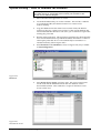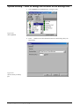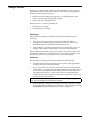
1
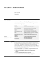
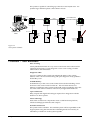
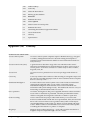
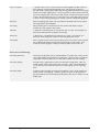
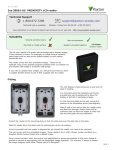
Net2 User Manual Version 1 ins-113 Date code: 010100 Contents Chapter 1 Introduction This manual............................................................................................... 3 Overview Net2 system........................................................................................ 3 Net2 hardware................................................................................... 4 Net2 software..................................................................................... 5 Chapter 2 Before setting up the system The structure of the software ................................................................. 7 Access levels or individual permissions? ............................................ 7 Software display ....................................................................................... 9 Chapter 3 About Hardware settings................................................................................... 11 Display screen.................................................................................. 12 ACU screen ...................................................................................... 13 Door settings ........................................................................................... 14 Net2 operators ......................................................................................... 15 Operator levels ................................................................................ 15 Timezones................................................................................................ 16 Timezone screen.............................................................................. 16 Access levels ............................................................................................ 17 Access level screen .......................................................................... 18 Users.......................................................................................................... 19 Access rights .................................................................................... 19 Tokens............................................................................................... 20 Actions Timed opening ................................................................................ 21 Code only ......................................................................................... 22 Public holidays ................................................................................ 23 Events........................................................................................................ 24 System backup ........................................................................................ 25 Chapter 4 Quick start step by step guide Net2 operators How to add a system operator ...................................................... 27 How to revise operator details ...................................................... 28 How to delete a system operator .................................................. 29 Contents 1 Timezones How to create a timezone............................................................... 29 How to change a timezone ............................................................ 31 How to delete a timezone .............................................................. 31 Access levels How to create an access level ........................................................ 32 How to change an access level ...................................................... 33 How to delete an access level ........................................................ 34 Users How to add a user........................................................................... 34 How to set a users validity ........................................................... 36 How to change a users validity.................................................... 36 How to delete a user ....................................................................... 36 How to issue a new token to a user .............................................. 37 Events How to configure an event report................................................. 38 Actions How to set bank holidays .............................................................. 40 How to set a code ............................................................................ 41 How to hold a door open during a timezone.............................. 42 How to change the door open time .............................................. 42 System backup How to manually back up the database....................................... 43 How to reinstate the database ....................................................... 44 How to change the location of the backup files .......................... 45 Chapter 5 What if the system is not working? Is the problem genuine?........................................................................ 47 Simple checks.......................................................................................... 48 Hardware ......................................................................................... 48 Software............................................................................................ 48 Paxton Access technical helpline......................................................... 50 Chapter 6 Appendix (i) Difference between code and PIN explained ........................... 51 (ii) List of illustrations......................................................................... 52 (iii) Glossary ........................................................................................... 53 Chapter 7 Specification .................................................................... 55 Contents 2 Chapter 1 Introduction This manual Overview This manual This manual is designed for anybody using a Net2 access control system. The manual should be read in full by anybody responsible for the administration of a Net2 system. The manual should be kept at hand for reference when using the system. Figure 1.1 Table showing the layout of this manual Section Function Overview An introduction to the system Before setting up the system Important information concerning the administration of the system About All system features explained in detail Quick start step by step guide Step by step guide to all common tasks enabling an operator to get up to speed on key functions in minutes What if the system is not working? System test and faultfinding information Appendix Useful information that is referred to throughout the document Specifications Full system specification Overview system The Net2 system is a revolutionary system with hardware and software developed simultaneously to meet the requirements of a modern day access control system. The hardware uses the latest in microchip technology allowing unprecedented levels of speed, resilience and cost. The software is based on the latest Windows interface and is developed to enable powerful functionality whilst maintaining ease of use. An access control system is an investment. The Net2 system ensures the future proofing of that investment in several ways: • Latest microchip technology offering solid, capable hardware platform • Use of FLASH memory allowing easy upgrades • Software can be extended in functionality with Modules • System can be extended with no redundancy of equipment Chapter 1 Introduction 3 The system is capable of controlling up to 200 doors and 10,000 users. For systems larger than this please contact Paxton Access. RS485/232 converter Up to 200 ACU's RS 485 Net2 ACU Optional desktop reader. Net2 ACU Door contact Net2 ACU Net2 ACU Maglock Reader and keypad Exit button Electric release Door 1 2 readers for read in and read out Door 2 Door 3 Barrier Figure 1.2 Net2 system schematic Overview Net2 hardware Ease of wiring Clearly labelled terminals on every access control unit remove the need for continual referencing to wiring diagrams. Clear colour coding of reader cables leads to fewer mistakes. Diagnostic LEDs An array of LEDs on the control unit indicate the status of key system features. This will aid commissioning and quick diagnosis of any problems should they occur. FLASH Memory FLASH memory in the access control units allows the downloading of new firmware to the control units from the PC. This will mean that as new features are added to Net2, systems in the field can be upgraded to allow the use of the latest software features without any changes to the hardware. Open architecture Relay outputs and digital and analogue inputs allow integration with the hardware of other systems. Latest technology State of the art electronic components create a solid hardware platform, which is both high performance and compact. Scaleable architecture The system will be scaleable. The smallest system will be expandable to the largest system using the same hardware building blocks and virtually no redundancy of hardware as the system expands. Chapter 1 Introduction 4 Communications Very high speed and resilient communications offer real time alarm reporting and the capability for very large systems. Distributed intelligence The Net2 single door control units provide full distributed intelligence down to individual doors. This gives greater system resilience and makes support and problem diagnosis easier. Also, event information can be retained when the system is running offline (2,300 events). Multi-technology The same control unit will support magstripe, keypads and proximity, mixed on a single site if required. Overview Net2 software Open architecture Microsoft Access database allows easy linking of data to other software systems. Ease of use Easy to learn user interface working in Microsoft Windows 95/98 and NT environments. Ease of commissioning Auto detection and numbering of access control units. No DIP switches to set or binary numbering to worry about, switch on the software and go! Modular The software has the capacity for features to be added as and when they are required. The modular structure enables the user interface to be as powerful as required whilst remaining simple. Chapter 1 Introduction 5 Chapter 1 Introduction 6 Chapter 2 Before setting up the system... The structure of the software Access levels or individual permissions? Software display The structure of the software The Net2 access control software comes in three parts. The application - This is the actual software program and is what is installed from the CD-ROM to the hard drive of the computer. Once the program has been installed the CD is no longer required to run the program. The default location for the program is C:\Program Files\Paxton Access\Net2. The system database This database contains all information that is relevant to a particular site i.e. user details, control unit and door information. If the database is deleted then the system will have to be recommissioned and setup again. The database containing all of this information is called NetSystem.mdb and the default location for this is C:\Net2 Access Control. The event database - This database contains event information. If the database is deleted then all events will be lost. The database containing all of this information is called NetEvents.mdb and the default location for this is C:\Net2 Access Control. Access levels or individual permissions? There are two ways in which the validity of users can be administered. Access levels The term Access level refers to a particular combination of access privilege and time. For example, an access level called Factory workers may allow users into the front door and factory door during working hours Mon-Fri. Several access levels can be configured and then applied to users of the system. Once set up, if an adjustment to the validity of a group of users is required, the access level can be changed affecting several users at once. Where there are a large number of users on the system, the administration time is reduced i.e. it is quicker to adjust a single access level than to adjust several individual user access levels. Also, where there are a large number of users, access levels can be quickly assigned, i.e. access permissions do not have to be set individually for each user. Chapter 2 Before setting up the system 7 When using access levels it is important to plan the structure. Users of the same validity should be grouped together by their access level. For example, if factory workers all had the same access privileges then an access level called Factory workers is configured. This access level is then applied to all members of that group. Similarly, access levels called Admin staff, Directors and Cleaners can be set up. Individual permissions Every user has an independent level of access that is unrelated to any other user. Each users validity has to be set and revised individually. Individual permissions are more appropriate where there are no large groups of users with the same access privileges i.e. smaller systems with fewer users and doors. Access levels or Individual permissions are selected in the user record, see figure 2.1. Figure 2.1 Access levels or Individual permissions Both Access levels and Individual permissions can be set up for different users on the same system. Chapter 2 Before setting up the system 8 Software display The Net2 software is based on the latest Windows interface. There are three windows: Main display Displays all system, event and user information. Treeview An Explorer style view used to navigate around the Net2 application. Shortcut bar A collection of shortcuts to key features. The Treeview and shortcut bars are optional and can be added/removed in the View menu, see figure 2.2. Figure 2.2 View menu Chapter 2 Before setting up the system 9 Chapter 2 Before setting up the system 10 Chapter 3 About Hardware settings Door settings Net2 operators Timezones Access levels Users Actions Events System Backup Hardware settings The term Hardware refers to the electrical components of the system i.e. control units, readers, cable etc. The hardware settings must be set by the installation engineers responsible for installing and commissioning the system. The Net2 software used to administer a system, must be configured to the system parameters e.g. number of control units, serial numbers of control units, reader types. The majority of these settings are automatically detected but some have to be set manually. When a system is modified the hardware settings may have to be revised. Chapter 3 About 11 Hardware settings display screen Figure 3.1 Hardware Figure 3.1 shows the hardware screen. This displays the access control units (ACUs) on the system. Name The name of the ACU is the same as its unique serial number. The tick beside the name of the ACU indicates that it is active. If an ACU has a problem it is possible that the software will continually attempt to communicate with the faulty ACU. This will reduce the efficiency of communications. Deleting the tick (by clicking on it) will disable the ACU and so prevent the software from attempting to communicate with it. Address Each ACU has a unique 8 digit address which is the same as the serial number, this allows the system to identify each ACU and distinguish between them. Type At the moment there is only a 1 door ACU available for the Net2 system. In the future 2 and 4 door ACUs may be developed for Net2. Version The version of firmware in the ACUs is displayed. Status The status of each ACU is displayed, i.e. Control not responding. Detect On installing the Net2 software for the first time the detect button is used to search the network and detect the ACUs. If any ACUs are replaced or added to the system, the Detect button is pressed to update list of ACUs. If the software detects an old version of firmware in any of the ACUs, a prompt will suggest that the latest firmware be automatically downloaded to those control units. Chapter 3 About 12 Reinstate This function allows selected control units to be reset and the information in the database to be downloaded. This may be useful if a control unit has been off line or if a backup database has to be retrieved. Replace If a Net2 control unit is faulty then it may need replacing with a new unit. The replace control unit wizard administers downloading the relevant settings and user information to the new control unit. Delete ACU A control unit can be deleted from the database using this feature. Once a control unit is deleted, all settings and events relating to this ACU will be lost permanently. Apply Commits changes to the database. Hardware settings ACU screen Figure 3.2 Hardware settings ACU Name The name of the ACU is the same as the address of the ACU. Door name On installation the door name is the same as the ACU name. It can be changed to allow easy referencing to particular doors. Door open time The door open time is the amount of time (in seconds) that the lock mechanism is open when the exit button is pressed or a valid user transaction has taken place. As default, the door open time is set to 7 seconds. This can be modified within the range of 1 5,000 seconds. Chapter 3 About 13 Timed opening This function allows a door to be automatically set to open within a timezone. For example, selecting Working hours from the drop down menu would mean that the door would automatically be open (no user token required) in this timezone. Reader configuration Name This is automatically set by the software. Reader 1 is Door name (In), reader 2 is Door name (Out). Reader configuration - Operating mode Each reader terminal (there are 2 on each ACU) has several different modes of operation. These have to be set manually. Options are: inactive, card only, card plus PIN, card plus code, desktop reader, PIN only, code only. For an explanation of the difference between code and PIN, refer to Appendix (i). Operating mode Description Access gained by Inactive There is no reader or keypad connected Card only There is a PROXIMITY or CARDLOCK reader connected at this reader position presenting a user token Card plus PIN There is a reader and a keypad connected at this reader position presenting a user token and entering a PIN number Card plus code There is a reader and a keypad connected to this reader position presenting a user token and entering a code Desktop reader There is a PROXIMITY, CARDLOCK or desktop reader connected at this reader position PIN only There is a TOUCHLOCK keypad connected at this reader position entering a PIN number Code only There is a TOUCHLOCK keypad connected at this reader position entering a code Figure 3.3 Table showing operating modes Door settings Figure 3.4 Door settings Chapter 3 About 14 All doors are displayed in the main display. Selecting a door from the treeview window allows door information to be viewed and changed, see figure 3.2. Net2 operators The Net2 software is password protected. This means that access to the program can be limited. Different levels of access to system features can be set for individual operators. The operator(s) responsible for issuing tokens, changing user validity etc. will require full access to system features. If a receptionist/security guard requires access to event and alarm information, this type of operator can be given access to only the features they require. Net2 operators operator levels There are 4 different levels of access to Net2 software features that can be assigned to an operator. System Engineer A System Engineer operator level is automatically assigned to the installer that commissions the system. Engineer privileges allow full access to all system features. Supervisor Supervisor operator level should be assigned to the administrators of the system. It allows full access to all features EXCEPT hardware settings. Standard Standard operator privilege allows the operator to view user details, timezone information, events etc but it is read only and nothing can be changed. Events only Events only allows the operator to view events. Other system details cannot be viewed or edited. Chapter 3 About 15 Timezones A timeslot is a time period on a particular day of the week. A timezone is a collection of timeslots applied to a week. An example of a timeslot is 9.00am 5.00pm Tuesday. An example of a timezone is Working hours 9.00am 5.00pm Mon-Fri. Timezones are used to control the access of users with respect to time. A user may be allowed access to certain doors in working hours for example. A maximum of 64 timezones can be created. There are three default timezones, these are At no time, Working hours and All day, every day. Timezones screen Figure 3.5 Timezones Timeslots can be created by holding down the right mouse button and dragging the mouse. The timeslot will snap to the nearest 15 minutes when doing this. To adjust the timeslot further the start and stop times can be manually adjusted using the start and stop traffic light controls. Timeslots can be dragged and dropped to any day of the week. Several timeslots can be applied to the same day. Right clicking the mouse button while the cursor is over a timeslot will duplicate the timeslot. The duplicate can be dragged to other days of the week. A unique timeslot configuration can be set up for public holidays. Apply Commits changes to the database. Delete Timeslots can be deleted from the timezone. The selected timeslot must be selected before pressing Delete. The Delete button on the keyboard may also be used to delete timeslots. Chapter 3 About 16 Access levels For systems with a large number of users, access through doors is most efficiently administered using access levels. For systems with few users (under 50) it may be that individual access permissions are more appropriate. An access level is a combination of timezones applied to the doors on a system. For example: Figure 3.6 Example access level Door Timezone Main entrance Working hours Stores At no time Front door Working hours This access level can be applied to a user to give them access through the main entrance and front door during working hours and access through the stores door at no time. An access level can be applied to many users. If an access level is changed then the access privileges will change for all users with that access level. There are two default access levels. These are No access and All hours, all doors. Naming access levels When using access levels to control the access privileges of users, the users are effectively grouped together by the access level. This makes the administration easier for systems with a large number of users. For example, access levels can be named after the departments that require different levels of access: Directors Managers Sales staff Figure 3.7 Examples of access level names Chapter 3 About Shift 1 factory staff Shift 2 factory staff 17 Access level screen Figure 3.8 Access level An access level can be created by selecting timezones from the drop down menu for each door. Chapter 3 About 18 Users Every user of the system has an individual record. The record contains all information specific to that user. Users are listed in alphabetical order. When the users are displayed in the treeview window, entering the first letter(s) of a users surname jumps straight to their record. User screen access rights The access privileges of a user are displayed in the user screen, see figure 3.9. Figure 3.9 User screen access rights Chapter 3 About User validity can be controlled by either Individual permissions or Access level permissions, this can be set here. If Individual permissions are set for a user then timezones are selected for each door thus creating an individual access level. If Access levels are set for a user then the relevant access level is selected from the drop down menu. 19 User screen tokens Figure 3.10 User screen - tokens Token is the generic term for the device a user carries. There are several types of user token, these include magstripe card, proximity token, proximity keyfob, proximity ISO card. A user can be issued with several user tokens. All tokens issued to a user will have the same access privileges. The token number can be entered by presenting to the desktop reader or by manually typing the number in. PINs can be assigned to users by entering the desired number in the PIN box. PINs must be unique and so duplicates are not allowed. AutoPIN will automatically generate a unique PIN for a user. Chapter 3 About 20 Actions Timed opening It is possible to hold open any door on the system within a specified timezone. For example, the main reception to a company is attended by a receptionist in working hours. In this timezone, the reception door can be automatically set to be open allowing visitors to enter the area. Outside this timezone, the door will be locked and users will be required to present their token to gain access. In the door screen, see figure 3.11, there is a Timed opening drop down menu. The relevant timezone can be selected. Figure 3.11 Timed opening Chapter 3 About 21 Actions Code only Where access is controlled through a door by a keypad only, PINs or codes can be used, for an explanation of the difference between code and PIN, refer to Appendix (i). Every door that is configured to operate using code only, is listed in the drop down menu in the treeview window, see figure 3.12. Figure 3.12 Code only Different codes can be set for every door configured to code only mode. Up to 50 codes can be validated on each door. Keypad codes can be from 4 to 8 digits long. Where several codes are valid on a single door, the probability of entering a valid code by randomly pressing buttons is increased. Increasing the number of digits in the user codes will dramatically reduce the likelihood of this happening. Chapter 3 About 22 Actions Public holidays Different access privileges may be required for public holidays. Days can be marked as public holidays and access can be set specifically for these days. The Public holidays screen allows you to select the correct dates, see figure 3.13. Figure 3.13 Public holidays Chapter 3 About In a timezone, timeslots can be set for Sun, Mon, Tues, Wed, Thurs, Fri, Sat AND public holidays. This allows different access privileges on public holidays. 23 Events Figure 3.14 Events All events are recorded by the software and can be viewed in the events screen. The event information appears in real time, i.e. as an event occurs it appears on the Events screen. By default the events are displayed sorted by time with the most recent event at the top. The pull down menu allows the number of events shown in the Events screen to be changed. Events from the last hour, day and 7 days can appear. The icons next to the pull down menu can be used to restrict the types of event that are displayed on the screen. Double clicking on a users event will jump you straight to the user record. The red and green buttons at the top of the main display are to control the updating of events. On a busy system events may be happening several times a second, the continually updating records may interfere with viewing events. Pressing the red button stops the Events screen from updating, this allows records to be viewed without further records coming through. A simple search may be performed when the red button is pressed. Any field can be searched for any entry by typing the entry in the search box and pressing the binocular icon. For example, typing access denied in the search box and pressing the binocular icon will display all access denied events. In the same way a search can be done on a person, door, date etc. The report wizard allows more complex reports to be configured. Shortcuts to the report wizard can be found in the shortcut bar and the Tools menu. Chapter 3 About 24 System backup All system and user information specific to a site is held in a database called Net2System.mdb. If this database is corrupted or lost/moved then the Net2 system will not work. For this reason it is essential that the database is routinely backed up to a location other than the hard disk of the PC. Options include floppy disk, network server, ZIP drive, DAT tape and CDR. The location of the database is set when installing the software. If the database is moved, the software must be deleted and reinstalled allowing the correct location of the database to be set. The default location is C:\Net2 Access Control\Net2System.mdb. The backup database is updated every time the Net2 application is closed. A new backup database is created every day and the title of the file includes the date, i.e. 990803 Net2System.mdb. Backup databases from the last 7 days are kept, i.e. once a backup database is over 7 days old it is automatically deleted. 7 days backup retention (set as default) can be changed by selecting Options in the Tools menu. The default location of the backup files is C:\Net2 Access Control\Backup. A backup copy of the database can be created manually by simply copying Net2System.mdb, refer to Quick start step by step guide/How to manually back up the database. If the database becomes corrupted then a backup copy will need to be reinstated. This involves moving the database to C:\Net2 Access Control and synchronising the information on the new database with that on the access control units, refer to Quick start step by step guide/How to reinstate the database. Chapter 3 About 25 Chapter 3 About 26 Chapter 4 Quick start step by step guide Net2 operators Timezones Access levels Users Events Actions System backup Net2 operators How to add a system operator 1. Double click on Add operator, see figure 4.1. 2. Select the name of the system operator from the drop down list of users. Figure 4.1 Add operator An operator must first be set up as a user. 3. Select the relevant operator rights from the drop down list, see figure 4.2. Chapter 4 Quick start step by step guide 27 Figure 4.2 Operator configuration wizard 4. Enter and confirm the operators password. 5. Press Finish to save changes and exit. Net2 operators How to revise operator details 1. Double click on the desired operator, see figure 4.3. 2. All details can now be revised. 3. Press Finish to save changes. Figure 4.3 Selecting an operator At least supervisor privileges are required to create or modify operators. Chapter 4 Quick start step by step guide 28 Net2 operators How to delete a system operator 1. Double click on the desired operator, see figure 4.3. 2. Set Operator rights to none. 3. Select Finish to save changes and exit. Timezones How to create a timezone 1. Double click on Add Timezone, see figure 4.4. 2. Enter the name of the new timezone, see figure 4.5. 3. Create the timezone required, see figure 4.6. Timeslots are created by holding down the mouse button and dragging the cursor. Figure 4.4 Add timezone Figure 4.5 Name the new timezone Chapter 4 Quick start step by step guide 29 Figure 4.6 Creating a timeslot Pressing the right mouse button whilst a timeslot is selected will copy the selection allowing it to be dragged and dropped to another time and day. 4. Select Apply to save changes to the timeslot. Chapter 4 Quick start step by step guide 30 Timezones How to change a timezone 1. Select the desired timezone from the pull down menu in the treeview window, see figure 4.7. 2. Make the necessary revisions to the timezone. 3. Select Apply to save changes. Figure 4.7 Changing a timezone Timezones How to delete a timezone 1. Select the desired timezone, see figure 4.8. 2. Select Delete. 3. Press Yes to delete the selected timezone. Figure 4.8 Deleting a timezone Chapter 4 Quick start step by step guide 31 Access levels How to create an access level 1. Double click on Add Access Level, see figure 4.9. 2. Enter the name of the new access level. 3. Select a timezone from the drop down menu for each of the doors on the list, see figure 4.10. 4. Select Apply to save changes. Figure 4.9 Select Add Access Level Figure 4.10 Creating an access level Chapter 4 Quick start step by step guide 32 Access levels How to change an access level Figure 4.11 Changing an access level 1. Select the desired access level from the pull down menu in the treeview window. 2. Make the required changes to the access level, see figure 4.11. 3. Select Apply to save changes. Chapter 4 Quick start step by step guide 33 Access levels Delete an access level 1. Select the desired access level, see figure 4.12. 2. Select Delete. 3. Press Yes to delete the selected access level. Figure 4.12 Delete an access level Users How to add a user to the system 1. Double click on Add User, see figure 4.13. 2. Enter the name of the user and select Next to continue. Figure 4.13 Add User Chapter 4 Quick start step by step guide 34 Pressing Tab will switch between fields. 3. Select the relevant option, see figure 4.14. Swipe card/token through desktop reader If you have a desktop reader then the token can be swiped now to assign it to the user. Allocate card/token later You may elect to create user records first and allocate tokens to users at a later date. Manually enter card/token number Where the number encoded onto the token is supplied, it may be entered manually. Figure 4.14 Add user wizard More than one token can be assigned to a user. 4. Select Next to continue. 5. If the details of the user are correct then press Finish to save changes and exit the wizard. 6. Other user details can be stored in the Other details tab in the user record. Presenting a token to the desktop reader will automatically start the add user wizard. Chapter 4 Quick start step by step guide 35 Users How to set a users validity Figure 4.15 Setting a users validity 1. Select the desired user from the pull down menu in the treeview window, see figure 4.15. 2. If using access levels Select the desired access level from the drop down menu and press Apply to save changes. If not using access levels Select Individual permissions and set the access privileges for the user. Press Apply to save changes. Users How to change a users validity 1. Select the desired user from the drop down menu in the treeview window, see figure 4.15. 2. Revise access privileges as required. 3. Press Apply to save changes. Users How to delete a user 1. Select the desired user from the drop down menu in the treeview window, see figure 4.15. 2. Press Delete record. 3. Select Yes to permanently delete the user. Chapter 4 Quick start step by step guide 36 Users How to issue a new token to a user Figure 4.16 Token screen 1. Select the relevant user from the treeview window. 2. Select the Tokens tab to display the token screen in the main display, see figure 4.16. 3. If you wish to delete the existing token then select it and press Delete. 4. If you are using a desktop reader then present the new token and select Yes to issue it to the current user. Otherwise manually enter the token number and press Add card. 5. Press Apply to save changes. Chapter 4 Quick start step by step guide 37 Events How to configure an event report Figure 4.17 Select Report from the shortcut bar 1. Select Report from the shortcut bar, see figure 4.17. 2. Select user(s) from the menu to include in the report by highlighting them and pressing Add. The selected users will appear in the right display window, see figure 4.18. Double clicking on a user from the listbox will add them to the selected users. Chapter 4 Quick start step by step guide 38 Figure 4.18 Report Wizard Step 1 of 4 3. In the same way, select the doors from the menu that are to be included in the report. Press Next to continue. 4. Select the start and end dates for the report, see figure 4.19. Figure 4.19 Report Wizard Step 3 of 4 All events are archived so a report can span back to from when the system was initially installed. 5. The report may be viewed on the screen or a hard copy can be printed. Pressing Finish will exit the wizard. Chapter 4 Quick start step by step guide 39 Actions How to set bank holidays Figure 4.20 Public holidays 1. Select Public holidays from the treeview window, see figure 4.20. 2. Dates can be selected from the drop down menu. 3. Press Apply to save changes. Chapter 4 Quick start step by step guide 40 Actions How to set a code Figure 4.21 Code only 1. Select Keypad codes from the treeview window, see figure 4.21, and select the relevant door. 2. Enter the code to be validated and press Add. 3. Press Apply to save changes. Up to 50 codes for each door can be added in this way. Chapter 4 Quick start step by step guide 41 Actions How to hold a door open during a timezone Figure 4.22 Select the desired door 1. Ensure that the desired timezone has been set up, refer to Quick start step by step guide/Timezones/How to set up a timezone. 2. Select the desired door from the pull down menu in the treeview window, see figure 4.22. 3. The Timed opening function is to allow the door to be held open in a particular timezone. Select the desired timezone from the drop down menu. Press Apply to save changes. Actions How to change door open time 1. Select the desired door from the pull down menu in the treeview window, see figure 4.22. 2. The door open time may be adjusted as required. Press Apply to save changes. Chapter 4 Quick start step by step guide 42 System backup How to manually back up the database 1. Ensure that the Net2 application is closed. 2. Open Windows Explorer and browse to C:\Net2 Access Control, see figure 4.23. The backup database is automatically updated up every time the Net2 application is shut down. A backup database is created every day and automatically deleted after 7 days (this can be changed by selecting Options in the Tools menu). The default location is C:\Net2 Access Control\Backup. Figure 4.23 Backing up the database 3. Copy Net2System.mdb and Net2Events.mdb by clicking the right mouse button over the files and selecting Copy. 4. The files may now be pasted to the desired location, e.g. floppy disk. Chapter 4 Quick start step by step guide 43 System backup How to reinstate the database The Net2System.mdb database contains all system information. Take care when moving it. If in doubt please contact your installer or the Paxton Access technical helpline. 1. Ensure that the Net2 application is closed. 2. Locate the database that you wish to reinstate. This will be a .mdb file in your backup folder, the default location is C:\Net2 Access Control\backup. 3. Copy this database into the Net2 Access Control folder, the default location for this is C:\Net2 Access Control. If the current database has not been deleted then Windows will ask if you would like to replace the existing file, press Yes. 4. Run the Net2 application. The application automatically checks that the ACU information matches up with the database information. If there is a discrepancy then the ACUs will automatically be reinstated. To reinstate manually follow steps 5 and 6. 5. Select Reinstate in the Hardware screen, see figure 4.24 (only available to System Engineers). 6. Press Select all then Apply, see figure 4.25. The access control units will be reset and the information from the new database will be downloaded to them. This could take a couple of minutes for each access control unit. Figure 4.24 Reinstate Figure 4.25 Reinstate the ACUs Chapter 4 Quick start step by step guide 44 System backup How to change the location of the backup files 1. Select Options in the Tools menu, see figure 4.26. 2. Press and browse to the desired location for the backup files, see figure 4.27. Figure 4.26 Select Options Figure 4.27 Select location for backup files Chapter 4 Quick start step by step guide 45 Chapter 4 Quick start step by step guide 46 Chapter 5 What if the system is not working? Is the problem genuine? Simple checks Paxton Access technical helpline Is the problem genuine? Please experience at first hand that the problem is genuine. Reported faults are invariably caused by user error. False alarms may be generated by: • Incorrect swiping of a magstripe card • Worn or damaged magstripe cards • Proximity device not presented within read range • Incorrect procedure at the PC If a genuine problem has been identified, firstly make sure that the problem can be duplicated. Document the exact nature of the problem, this will enable your installer and the Paxton Access technical help department to solve the problem quickly. Once the problem has been identified, duplicated and documented, perform the simple checks in the next section. Chapter 5 What if the system is not working? 47 Simple checks Firstly try to establish if the problem is with the hardware or the software. The hardware of the system is the readers, control units, power supplies etc. Examples of hardware problems are: • Reader not acknowledging user tokens, i.e. no flashing LEDs on the reader when the token is presented/swiped. • Electric lock not releasing the door Examples of PC or software problems are: • Run time error message • Unexpected error message Hardware If the problem is relating to the hardware of the system then check the following: 1. On every access control unit (1 for each door) there should be a heartbeat LED flashing at about 60 times per minute. If this is not flashing then there is a problem with that control unit. 2. If the problem is concerning readers then try some known good user tokens on that reader to ensure that it is not just a damaged token. If the problem persists then contact your installer. If you do not know who installed the system then contact the Paxton Access technical helpline, refer to What if the system is not working?/Paxton Access technical helpline. Software If the problem is relating to the software then check the following: 1. Close down the PC and restart the software with no other applications running. This may rectify the problem. 2. Set up a test token (i.e. user name Test Card) and do a walk round all of the readers. All of the events should have been reported at the PC. If no events are reported then ensure that the interface connecting to the PC COM port has power. If only some events are reported then the problem is likely to be hardware related, refer to What if the system is not working?/Simple checks/Hardware. Ensure that the update button in the events screen is enabled, see figure 3.14. If it is not then no events will be reported! 3. Confirm that the validity of user tokens is the same on the PC as on the system. Reinstate the database to confirm this. This is done by pressing the Reinstate button in the Hardware screen, see figure 5.1. Chapter 5 What if the system is not working? 48 Figure 5.1 Reinstate the ACUs Press Select all and Apply. This will reset each control unit and download all of the relevant database information to each one. If the problem persists then contact the Paxton Access technical helpline, refer to What if the system is not working?/Paxton Access technical helpline. Chapter 5 What if the system is not working? 49 Paxton Access technical helpline Paxton Access offer a telephone technical help service. This is designed to assist customers with technical problems. Many technical problems can be solved by following advice given over the phone, however many problems will require an installer to attend site. To qualify for technical support, a valid technical support ID number is required. This number is generated from the software, see figure 5.2. The technical support ID number will only be valid if the software had been registered. Figure 5.2 Generating the technical support ID number To assist our technical help staff to diagnose any problems quickly please ensure that: • The person calling has full details of the problem at first hand • The person calling has a working knowledge of the Net2 system • Details of the system are at hand i.e. number of doors/users, type of readers • The person calling has read this manual and has followed its guidelines and simple checks • The person calling has the technical support ID number The Paxton Access technical helpline is available Mon-Fri 8.30am-5.30pm. +44 (0) 1273 480291 Chapter 5 What if the system is not working? 50 Chapter 6 Appendix (i) Difference between code and PIN explained (ii) List of illustrations (iii) Glossary Appendix (i) Difference between code and PIN explained PIN stands for Personal Identification Number. This is a number that is specific to an individual user. A user code can be common to many users. Example of code only: A keypad has two codes to control the access of 1,000 users through an access point. 300 users use one code and 700 use the other. Codes are very quick to setup; thousands of users can be given access to an area if the code is disclosed. Access privileges can be adjusted for groups of users, where the users are grouped together by a common code. Example of PIN only: A keypad controls the access of eight users through a door. Each of the eight users has their own PIN, which they use to gain access. Using PINs mean that access rights can be changed for every individual without affecting other users. PINs also allow users to be identified by the system for reporting purposes. However, more numbers valid on a keypad will increase the chances of guessing a correct number. This means that a non-authorised person can gain access by randomly pressing keys on the keypad. To reduce these risks to an acceptable level it is necessary to increase the number of digits in the PIN. Example of card plus code: A proximity reader and a keypad are used to control access through a door. A user is required to present their proximity card to the reader and enter a valid code. This involves two elements of security possession and knowledge. The possession of the card is required AND a valid code has to be known. If the card is lost it cannot be used on its own. If the code is discovered it cannot be used without a valid card. Example of card plus PIN: A magnetic stripe reader and a keypad is used to control the access through a door. A user is required to swipe their card and enter their PIN number. Only the combination of that user card AND that user PIN number is acceptable. This involves both possession and knowledge but increases security even further. If a user card is lost it can only be used to gain access when used with the specific PIN number. For security reasons bank cash machines use a card plus PIN system. Chapter 6 Appendix 51 Appendix (ii) List of illustrations Figure Description 1.1 Table showing the layout of this manual 1.2 Net2 system schematic 2.1 Access levels or Individual permissions 2.2 View menu 3.1 Hardware 3.2 Hardware settings 3.3 Table showing operating modes 3.4 Door settings 3.5 Timezones 3.6 Example access level 3.7 Examples of access level names 3.8 Access level 3.9 User screen access rights 3.10 User screen tokens 3.11 Timed opening 3.12 Code only 3.13 Public holidays 3.14 Events 4.1 Add operator 4.2 Operator configuration wizard 4.3 Selecting an operator 4.4 Add timezone 4.5 Name the new timezone 4.6 Creating a timeslot 4.7 Changing a timezone 4.8 Deleting a timezone 4.9 Select Add Access Level 4.10 Creating an access level 4.11 Changing an access level 4.12 Delete an access level 4.13 Add user 4.14 Add user wizard 4.15 Setting a users validity 4.16 Token screen 4.17 Select Report from the shortcut bar 4.18 Report Wizard Step 1 of 4 4.19 Report Wizard Step 3 of 4 Chapter 6 Appendix 52 4.20 Public holidays 4.21 Code only 4.22 Select the desired door 4.23 Backing up the database 4.24 Reinstate 4.25 Reinstate the ACUs 4.26 Select Options 4.27 Select location for backup files 5.1 Reinstate the ACUs 5.2 Generating the technical support ID number 6.1 List of illustrations 6.2 Glossary 7.1 Specifications Appendix (iii) Glossary General access control terms Access control system An access control system comprises input for identification (e.g. a keypad or reader), intelligent electronics for decision making and outputs for operating access point hardware and the access point hardware itself (e.g. locks, barriers). Access Control Unit (ACU) A general term to describe a range of devices which have the control electronics and intelligence to make the decision to allow access at one or several points. It will have connectors or cables ready to link to readers, keypads, locks, etc. Access level An access level is a particular level of access privileges with relation to time. Coercivity Coercivity relates to the resilience of the encoding of a magnetic stripe card. Hi coercivity encoded magstripe cards are more resilient to data corruption than Lo coercivity cards. Distributed intelligence In a networked access control system access control units are linked and communicate with each other or a PC used to control the system. Distributed intelligence means that the access control units hold user information and system settings locally. This enables the ACUs to carry on functioning if communications links are severed. Door open time An electric locking device has power supplied/denied to release and allow access when a valid token is presented. The time period that the electric release is energised/de-energised is referred to as the door open time. Event recording Access control units may be provided with memory to record events. Events recorded should include the access point details, date, time and user ID for each occasion when access is granted. Many other events may be recorded depending on the system e.g. details of access denied and alarm events. Where events are recorded the access control unit will be capable of sending the information to a printer or computer. Magstripe Magnetic stripe reading technology cards with a number encoded on a magnetic stripe are swiped through a slot on a reader. Chapter 6 Appendix 53 Network system A system where access control units are linked together by data cable for the exchange of information between units. The purpose of this is to provide easier configuration and better management information for larger and more complex applications. All access points on the system can be set up from a single point. The access control units on network systems record events. Most systems allow for a computer to be connected to the network to allow control and reporting to be carried out from a dedicated program. Photo ID Where a photograph of the user is printed or attached to their user token allowing them to be identified. Proximity The proximity device is held close to the reader and sends a unique number by radio signal to the reader. Timeslot A timeslot is a time period on a particular day of week. An example of a timeslot is between 9am and 5pm on Tuesday. Timezone A timezone is a combination of timeslots in a week. An example of a timezone is Working hours between 9am and 5pm Mon to Fri. User token This is a generic term for the devices that users of an access control system use to identify themselves and gain entry through access points. User tokens may be magstripe cards, proximity keyfobs, smart cards, etc. Paxton Access terminology Proximity ISO card ISO cards are the same size as standard bank or credit cards. They can be used with standard card printers for photo ID. They also have a magnetic stripe that can be encoded for use with other systems such as vending. Proximity keyfob Keyfobs are for applications where convenience is important. They are made of hard plastic and will fit onto a keyring. They can be attached to car/house keys for reduced losses, hence reducing the cost of replacing fobs. Proximity token Tokens are about credit card size but are thicker. They can be used from inside wallets or handbags. Adhesive plastic stickers can be applied for photo ID and the slot in the tokens makes them ideal for use with low cost badge clips. Chapter 6 Appendix 54 Chapter 7 Specifications Net2 standard plus software Maximum number of users Maximum number of doors per data line † Net2 standard software Maximum number of users Maximum number of doors per data line † Reading technologies supported 10,000 200 2,000 50 All Paxton Access readers: PROXIMITY, CARDLOCK magnetic stripe, TOUCHLOCK keypads All users, all access points All users Up to 250 Up to 64 Yes Yes Yes unlimited 4 levels Individual password protection Provides fast access to user records Yes Reported to software and output for local sounder at door Reported to software and output for local sounder at door Screen reports on recent events Yes Microsoft Access 97 Yes - including Word, Excel, Access, etc Manual backup required Yes 1 to 5,000 seconds Yes - all equipment that can be switched by clean relays Individual access rights by access point Individual timezones Access levels Timezones Read in and read out Card plus PIN (Personal identification number) PIN only entry Number of system operators System operator privileges System operator log on to software Desk top reader Advance entry of Bank Holidays Door held / wedged open alarm Door forced alarm Instant reports Printed reports from entire access event history Database format Data available to other programs Timed backup of event log Fail open (fail safe) locks Door open time Operates gates, barriers, turnstiles, etc Network Details Communications with other control units RS485 full duplex 115,200 BAUD Maximum number of control units 200 Full distributed intelligence Yes Off line memory in access control units 2,300 events Access control unit user card capacity 10,000 Paxton Access proximity devices or magstripe cards Access control unit user card capacity 10,000 bank / credit magstripe cards Details of supported readers Magnetic stripe readers CARDLOCK Reader life >1,000,000 swipes Proximity readers PROXIMITY Reader life Unlimited token reads Keypads TOUCHLOCK membrane or TOUCHLOCK stainless steel Keypad life (key presses) >100,000 membrane or > 1,000,000 for stainless steel Water resistance All readers IPX7 (submersible) except membrane keypad IPX5 Finishes of CARDLOCK and TOUCHLOCK Black, brass or satin chrome Finish of PROXIMITY Black Finish of TOUCHLOCK stainless steel Stainless steel and satin chrome † Net2 standard and standard plus software support one data line Minimum PC minimum specification: Pentium PII/300 processor, 64 Mbytes RAM, UDMA hard disk with 1Gbyte free space, 800 x 600, 256 colour monitor (SVGA), a free UART 16550 serial port, mouse, keyboard and a CD ROM drive 4 x or better. Chapter 7 Specifications 55 Network communications Network communications cable Maximum length of communications bus Access Control Unit Number of doors per control unit Memory in the event of complete power failure Backup batteries ensure operation of Connections in the access control unit for each of the doors Readers Keypads Analogue / digital inputs 5 amp relay outputs (NC, and NO) 1 amp FET controlled output Reader to access control unit distances TOUCHLOCK keypad * TOUCHLOCK keypad stainless steel * CARDLOCK reader * PROXIMITY reader* Access control unit power requirement details Required supply voltage Maximum current for access control unit Maximum current for Paxton Access magstripe readers Maximum current for Paxton Access proximity readers Maximum current for Paxton Access keypads Maximum current for other keypads and readers Maximum current for locks Access control unit dimensions Board size Recommended minimum space for board in other manufacturer’s enclosures Board weight NETWORK RS485 / 232 communications converter Size Communications protocols Maximum serial cable distance to PC Low voltage power supply Desktop reader details Type of reader Paxton Access dual technology desktop reader Size of Paxton Access dual technology desktop reader Maximum distance to access control unit Black plastic housing Size Features PSU enclosure size Details to be confirmed Belden® 8723 (individually shielded pairs) * 1,000m 1 All system settings and user details are retained for 7 days Entire system except PC - control of access continues 1 or 2 (in, in/out) 1 or 2 (in, in/out) 4 (default uses: exit button, door contact, PSU monitor, tamper) 2 (default use: lock relay and door bell relay) 1 (sinks up to 1A at 12Vdc, default use: local door alarm) 30m 30m 100m 50m 9V to 15V dc 350mA at 12Vdc (allow extra for FET output) 65mA 70mA 45mA See reader manufacturer’s literature See lock manufacturer’s literature 102 x 116 x 30mm high 200 x 170mm high 190g 80 x 50 x 20mm RS232 to PC, RS485 to access control units 7m 250mA 12V dc The reader type used at the doors on site may be used or: Reads magstripe cards and Paxton Access proximity devices 160 x 90 x 30 mm As for other reader distances noted above 175 x 170 x 40mm Tamper switch, cable tie loops, cable entry knock outs * All reader and data cables should be segregated from mains power cables to avoid interference. IEE Regulations and normal good practice should be observed. Belden cables or exact electrical equivalents must be used. ®Windows 95/98, Windows NT, Access, Excel and Word are Registered Trademarks of Microsoft Corporation Inc. ® Belden is a Registered Trademark of Cooper Industries Inc. Chapter 7 Specifications 56 Net2 User Manual