1
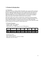
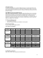
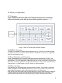
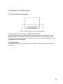
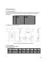
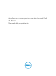
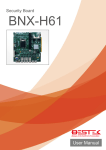
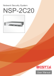
DMP SATA DOM SDM-4G-V SDM-8G-V SDM-16G-V Datasheet Copyright The information in this manual is subject to change without notice for continuous improvement in the product. All rights are reserved. The manufacturer assumes no responsibility for any inaccuracies that may contain in this document, and makes no commitment to update or to keep current information contain in this manual. No part of this manual may be reproduced, copied, translated or transmitted, in whole or in part, in any form or by any means without the prior written permission of the DMP Electronics Inc. Copyright 2012 DMP Electronics Inc. Special Notice to Users DMP Electronics Inc. provides no warranty with regard to this manual, the software, or other information contained herein and hereby expressly disclaims any implied warranties of merchantability or fitness for any particular purpose with regard to this manual, the software, or such other information. In no event shall DMP Electronics be liable for any incidental, consequential, or special damages, whether based on tort, contract, or otherwise, arising out of or in connection with this manual, the software, or other information contained herein or the use thereof. DMP Electronics reserves the right to make any modification to this manual or the information contained herein at any time without notice. The software described herein is governed by the terms of a separated user license agreement or label sticker. This product contains software owned by DM&P and licensed by third parties. Use of such software is subject to the terms and conditions of license agreements enclosed with this product. Software specifications are subject to change without notice and may not necessarily be identical to current retail versions. Updates and additions to software may require an additional charge. Subscription to online service providers may require a fee and credit card information. Financial services may require prior arrangements with participating financial institution. Contents Chapter 1 Product Introduction 1.1 Overview……………………………………………………………….….….2 1.2 Product Features………………………………………………………….….2 Chapter 2 Specifications 2.1 2.2 2.3 2.4 Environmental Specifications…………………………………………4 System Reliability………………………………………………………4 Power Requirement……………………………………………………5 RoHS compliance…………………………………………………….5 Chapter 3 Theory of operation 3.1 Overview………………………………………………………….…………..7 3.2 SATA II Controller……………………………………………………….……7 3.3 Error Detection and Correction………………………………………………7 3.4 Wear-Leveling………………………………………………………………...7 3.5 Bad Blocks Management…………………………………………………….8 Chapter 4 Installation Requirements 4.1 SAT ADOM Pin Directions……………………………………………..…10 4.2 Electrical Connections for DMP SATA DOM……………………….……10 4.3 Device drive…………………………………………………………………10 Chapter 5 Specifications 5.1 Pin Assignment………………………………….……………………….…12 5.2 Mechanical Dimensions…………………………………………………....12 5.3 Performance………………………………………………………………...12 5.4 Seek Time…………………………………………………………………...13 5.5 NAND Flash Memory……………………………………………………….13 Chapter 6 Product ordering information 6.1 Ordering information………………………………………………………...15 Chapter 1 1 1. Product Introduction 1.1 Overview DMP Serial ATA Disk on Module (DMP SATA DOM) series supports SATA III standard (3.0Gb/s) interface with good performance and thus performs faster data transfer rate. Moreover, DMP SATA DOM is designed as the smallest form factor size that could enhance compatibility with various design applications. Another advanced design of DMP SATA DOM is the connector with latch and thus such innovative mechanical design could improve data transfer reliability while device operating. DMP SATA DOM is also suitable in industrial field. It effectively reduces the booting time of the operation system and the power consumption is less than a hard disk drive (HDD). DMP SATA DOM can work under harsh environment. DMP SATA DOM complies with ATA protocol, no additional drives are required, and the DMP SATA DOM can be configured as a boot device or data storage device. 1.2 Product Features ‧Interface: Serial ATA II (3.0Gbps) ‧Capacity: 4GB ~ 16GB (MLC) ‧Data transfer rate: (In MB/s, Based on Intel ATOM platform) SATA Density 4GB 8GB 16GB Item no SDM-4G-V SDM-8G-V SDM-16G-V Seq Seq 512KB Read Write R.R. 42.06 6.398 41.36 44.58 6.490 44.19 53.39 11.25 52.86 Table 1: Data transfer rate 512KB R.W. 6.177 6.271 9.604 4KB R.R 8.972 10.53 11.34 4KB R.W. 0.64 0.61 0.62 ‧Access time: 0.3ms ‧Error Correction Function Built-in ECC corrects up to 15-bit per 512-Byte ‧Dimension: 30 x 21 x 4.8 mm 2 Chapter 2 3 2.Specifications 2.1 Environmental Specifications 2.1.1 Temperature Range ‧Operating Temperature Range: 0°C to +70°C ‧Storage Temperature Range: -40°C to +85°C 2.1.2 Humidity Relative Humidity: 10-95%, non-condensing 2.1.3 Shock and Vibration Reliability Test Conditions Vibration 7 to 2000 Hz, 20G Mechanical Shock Duration: 10ms, 50G Table 2: Shock / Vibration Testing for DMP SATA DOM 2.2 System Reliability 2.2.1 ECC Technology High reliability based on the internal error correct code (ECC) function. Built-in ECC corrects up to 15-bit per 512-Byte. 2.2.2 Mean Time between Failures (MTBF) Table 2 summarizes the MTBF prediction results for various DMP SATA DOM configurations. The analysis is performed using a RAM Commander, failure rate prediction. ‧Failure Rate: The total number of failures within an item population, divided by the total number of life units expended by that population, during a particular measurement interval under stated condition. ‧Mean Time between Failures (MTBF): A basic measure of reliability for repairable items: The mean number of life units during which all parts of the item perform within their specified limits, during a particular measurement interval under stated conditions. Product DMP SATA DOM Condition Environment 25°C MTBF (Hours) > 3,000,000 Table 3: DMP SATA DOM MTBF 2.2.3 Transfer Mode DMP SATA DOM supports the following transfer mode: PIO Mode: 0~4 Multiword DMA: 0~2 Ultra DMA: 0~6 4 2.2.4 Data Transfer The DMP SATA DOM uses a superior DMA technology to transfer data between the host and the NAND flash interface. The DMA technology transfers data at a very high rate in both directions (read and write) and in doing so, effectively decreases the micro processor loading. 2.2.5 SMART Command and Data Security DMP SATA DOM provides SMART command support that allows users to read spare and bad block information. The users can thus evaluate driver health at run time and receive an early warning before the flash drive lifespan ends. It provides security commands for users to lock and unlock the drive by password or a hardware switch. In additions, customized commands can be utilized to erase blocks for those users who require the highest level of security. 2.3 Power Management Prevent SATA corruption Automatic Sleep and wake-up mechanism to save power 2.3.1 DC Input Voltage 5V (±5%) single power supply operation 2.3.2 Power Consumption Item no SDM-4G-V Item no SDM-8G-V Item no SDM-16G-V Operation Mode Stand by Read Write Slumber 3.3V(mA) Point A 1 24 36 0 1.8V(mA) Point B 136 223 171 88 Total (mW) A*3.3V+B*1.8V 248 481 427 158 Vcc in Total (mW) Point C 275 525 461 176 Operation Mode Stand by Read Write Slumber 3.3V(mA) Point A 1 25 36 0 1.8V(mA) Point B 136 230 172 88 Total (mW) A*3.3V+B*1.8V 248 497 428 158 Vcc in Total (mW) Point C 275 558 497 176 Operation Mode Stand by Read Write Slumber 3.3V(mA) Point A 1 26 45 0 1.8V(mA) Point B 136 236 174 88 Total (mW) A*3.3V+B*1.8V 248 511 462 158 Vcc in Total (mW) Point C 275 576 649 176 Table 4: DMP SATA DOM power consumption 2.4 RoHS compliance DMP SATA DOM is fully compliant with RoHS directive. 5 Chapter 3 6 3 Theory of operation 3.1 Overview Figure 2 shows the operation of DMP SATA DOM from the system level, including the major hardware blocks. As the diagram shown, SATA II controller communicates with SATA II host interface directly. Also SATA II controller supports one flash IC. Figure 1: DMP SATA DOM Internal Block Diagram 3.2 SATA II Controller The SATA II controller is 3.0Gbps, and supports hot-plug. This SATA II controller support four flash IC and communicates with host interface, this SATA II controller can support the flash ICs for 4kbyte per page. 3.3 Error Detection and Correction Highly sophisticated Error Correction Code algorithms are implemented. The ECC unit consists of the Parity Unit (parity-byte generation) and the Syndrome Unit (syndrome-byte computation). This unit implements an algorithm that can correct 15 bits per 512 bytes in an ECC block. Code-byte generation during write operations, as well as error detection during read operation, is implemented on the fly without any speed penalties. 3.4 Wear-Leveling Flash memory can be erased within a limited number of times. This number is called the erase cycle limit or write endurance limit and is defined by the flash array vendor. The erase cycle limit applies to each individual erase block in the flash device. DMP SATA DOM uses a static wear-leveling algorithm to ensure that consecutive writes of a specific sector are not written physically to the same page and block in the flash. This spreads flash media usage evenly across all pages, thereby extending flash lifetime. 7 3.5 Bad Blocks Management Bad Blocks are blocks that contain one or more invalid bits whose reliability are not guaranteed. The Bad Blocks may be presented while the DMP SATA DOM is shipped, or may develop during the life time of the SSD. The Bad Blocks will not exceed more than 6.7% of the total device volume. When the Bad Blocks are detected, it will be flagged, and not be used anymore. The DMP SATA DOM implement Bad Blocks management, Bad Block replacement, Error Correct Code to avoid data error occurred. The functions will be enabled automatically to transfer data from Bad Blocks to spare blocks, and correct error bit. 8 Chapter 4 9 4 Installation Requirements 4.1 SATA DOM Pin Directions Figure 2: Signal Segment and Power Segment 4.2 Electrical Connections for DMP SATA DOM A Serial ATA device may be either directly connected to a host or connected to a host through a cable. For connection via cable, the cable should be no longer than 1meter. The SATA II Interface has a separate connector for the power supply. Please refer to the pin description for further details. 4.3 Device drive No additional device drivers are required. The DMP SATA DOM can be configured as a boot device. 10 Chapter 5 11 5 Specifications 5.1 Pin Assignment DMP SATA DOM is designed within SATA II Interface. Particularly, its built-in power pin enables the device more compactable. Table 4 demonstrates DMP SATA DOM pin assignments. Table 5: DMP SATA DOM Pin Assignment 7 Pin Signal Function Pin 1 GND Shielding Pin 2 A+ Differential signal to A+ Pin 3 ADifferential signal to APin 4 GND Shielding Pin 5 BDifferential signal to BPin 6 B+ Differential signal to B+ Pin 7 GND/VCC (+5V) Shielding/Power 5.2 Mechanical Dimensions Figure 3: DMP SATA DOM mechanical dimensions 5.3 Performance A. Burst Speed Rate: 300MB/sec. B. Data Transfer Rate SATA Seq Seq 512KB Item no Density Read Write R.R. 4GB SDM-4G-V 42.06 6.398 41.36 8GB SDM-8G-V 44.58 6.490 44.19 16GB SDM-16G-V 53.39 11.25 52.86 Table 1: Data transfer rate 512KB R.W. 6.177 6.271 9.604 4KB R.R 8.972 10.53 11.34 4KB R.W. 0.64 0.61 0.62 12 5.4 Seek Time DMP SATA DOM is not a magnetic rotating design. There is no seek or rotational latency required. 5.5 NAND Flash Memory DMP SATADOM uses Multi Level Cell (MLC) NAND and, which are non-volatility, high reliability and high speed memory storage. For MLC, there are four statuses 00, 01, 10 and 11 of one cell. Read or Write data to flash memory for DMP SATA DOM is controlled by micro processor. 13 Chapter 6 14 6 Product Ordering information 6.1 Ordering information SDM-4G-V: DMP SATA DOM Pin Vertical with 4GB capacity. SDM-8G-V: DMP SATA DOM Pin Vertical with 8GB capacity SDM-16G-V: DMP SATA DOM Pin Vertical with 16GB capacity. 15