1
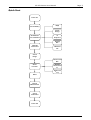
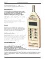
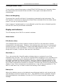
CR:270 Series User Manual CR:270 Series Sound Level Meters User Manual This manual, the software to which it relates, the program code and drawings are all: © Copyright Cirrus Research plc 1989-2015 Page 1 Page 2 CR:270 Series User Manual The content of this manual, any illustrations, technical information and descriptions within this document were correct at the time of going to print. Cirrus Research plc reserves the right to make any changes necessary, without notice, in line with the policy of continuing product development and improvement. No part of this publication may be duplicated, reprinted, stored in a data processing system or transmitted by electronic, mechanical, photographic or other means, or recorded, translated, edited, abridged or expanded without the prior written consent of Cirrus Research plc. No liability is accepted for any inaccuracies or omissions in this manual, although due care has been taken to ensure that is it complete and accurate as possible. Accessories supplied by Cirrus Research plc have been designed for use with the instrumentation manufactured by Cirrus Research plc. No responsibility is accepted for damage caused by the use of any other parts or accessories. In order to take account of a policy of continual development, Cirrus Research plc reserves the right to change any of the information contained in this publication without prior notice. Produced by Cirrus Research plc, Acoustic House, Bridlington Road, Hunmanby, North Yorkshire, YO14 0PH, United Kingdom. © Copyright Cirrus Research plc 2015 Reference Number 01/03/CR:270/01 Document Printing Date Tuesday, 23 June 2015 CR:270 Series User Manual Page 3 Overview. ..................................................................................................................... 4 Recommended Accessories .............................................................................................4 Quick Start ................................................................................................................... 5 First time use. .............................................................................................................. 6 Fundamental Precautions. ..............................................................................................6 CR:270 Controls............................................................................................................ 7 Weighting .....................................................................................................................7 Range ..........................................................................................................................7 Response .....................................................................................................................8 Display.........................................................................................................................8 Max Hold ......................................................................................................................8 Reset Display ................................................................................................................8 Reset All.......................................................................................................................9 Calibration Adjustment. ..................................................................................................9 CR:273 & CR:274 Additional Functions ....................................................................... 10 General Overview ........................................................................................................ 10 Controls ..................................................................................................................... 10 Switching on the filters ............................................................................................................ 10 Selecting the Active filter ......................................................................................................... 10 Turning off Octave filters ......................................................................................................... 11 Filters and Weighting ................................................................................................... 11 Display and Indicators ................................................................................................ 11 Annunciators .............................................................................................................. 11 Full (Centre colon) .................................................................................................................. 11 Overload (+) .......................................................................................................................... 11 Battery low ............................................................................................................................ 11 Summary ............................................................................................................................... 12 Calibration .................................................................................................................. 13 Recommended Calibrators ............................................................................................ 13 Procedure ................................................................................................................... 13 Replacing the batteries............................................................................................... 15 Types of batteries ........................................................................................................ 15 Selection of Hearing Protection .................................................................................. 16 Example of the Octave Band Method .............................................................................. 17 Example of the HML Method ......................................................................................... 18 Rating Plate Information ............................................................................................ 19 Specification ............................................................................................................... 24 CE Certificate of Conformity ....................................................................................... 25 Equipment Description ............................................................................................... 25 Warranty Information. ............................................................................................... 26 Cirrus Research Offices .............................................................................................. 27 Page 4 CR:270 Series User Manual Overview. The CR:270 series of instruments is a range of Digital Integrating Sound Level Meters. The instruments in the range are: CR:271 CR:272 CR:273 CR:274 Type Type Type Type 1 2 1 2 Integrating Integrating Integrating Integrating Averaging Averaging Averaging Averaging Sound Level Meter Sound Level Meter Octave Band Sound Level Meter Octave Band Sound Level Meter This manual will refer to the CR:27x where the features are common to all the instruments listed above. Where there are differences between both the specification and operation of any of the instruments, these will be stated with reference to the particular instrument. The CR:270 series have all the features necessary to make a wide variety of Industrial noise measurements, and they comply with the Standard IEC 804 (BS 60804) for Inte grating Averaging Sound Level Meters, conventionally called 'Leq Meters' and IEC 651 (BS 60651) for Sound Level Meters, meeting both these specifications to Type 1 and Type 2 accuracy where applicable. The CR:273 and CR:274 instruments also features octave band filters that meet or exceed the requirements of IEC 1260. The CR:270 series of instruments are ideally suited to the following uses: Determination of Leq for assessment of hearing loss risk. Measurement of machine noise. Sound Power Level measurements by the survey method. Specification of hearing defenders using the octave band method (CR:274 & CR:273 ) or HML method (CR:272 & CR:271) Measurement of the absolute peak of a signal. Measurement of the 'Peak' action level under the EC directive. Recommended Accessories A full range of accessories are available for the CR:270 Series. These include the following: Item Description CR:513A Acoustic Calibrator UA:237 Windshield CK:250 Attache Case CP:22 Pouch These accessories can be purchased at a later date. The attache case allows the sound level meter, acoustic calibrator, windshield and miscellaneous accessoires to be transported safety. Please refer to the current Cirrus Research pricelist for full details of the accessories available for the CR:270 series of instruments. CR:270 Series User Manual Quick Start Power On Check Battery dB(A) 50-100 Range Set Switches for Calibration 'S' Response Display SPL Calibrate Instrument Max Hold Off Check Range Sound Level SPL Select Function Average Sound Level Leq Peak Level LPeak(C) Reset Record Measurement Check Calibration Power Off Page 5 Page 6 CR:270 Series User Manual First time use. The instrument should be inspected for any signs of damage. The two batteries type 6F22 (NEDA 1604 or PP3) should be fitted into the battery compartment. See section 8 for details of changing the batteries. Ensure that the MAX HOLD button is out. This is the lower of the three push buttons. If this is not done, the display will be held. Push RESET ALL to ensure all functions are reset to zero. The lower of the four slide switches, WEIGHTING, should be pushed to the right hand position marked dB(A). The upper of the four slide switches, DISPLAY, should be pushed to the right hand position marked SPL. When using the CR:274 octave band instrument, the octave band filter may be enabled when the instrument is switched on. Hold down the OCTAVE FILTER button for 5 seconds until none of the filter indicators are lit. See section 6. If so, the meter is ready to calibrate and use. Fundamental Precautions. Always check the battery before and after each measurement. The CR:270 monitors the battery continuously while operating. Ensure that the black HOLD button is OUT. If this is not done, the display will not freeze the last reading and the central colon will be displayed in the LCD. Always check the instrument calibration before and after each measurement. To obtain the most accurate readings, the microphone should be pointed at the source of the noise and held away from the observer. In wind over 5ms-1 a foam windshield should be used. The UA:237 windshield should be used with the CR:270. Do not operate the meter continuously at temperatures greater than 40 degrees celsius or you will get errors of reading and the instrument may suffer deterioration. Remember to switch off after use or the batteries may leak and rot the case. Never operate the unit in rain or snow. While the CR:270 is not affected by damp, actual water in the microphone will cause errors of reading and may permanently damage the capsule. Keep the instrument still while measurements are being taken. If the meter is being used out of doors, care should be taken to keep the unit away from large objects which will cause sound reflections and thus give incorrect readings. When the CR:270 is used inside buildings, thought should be given to the best site. If in doubt make several measurements in different positions. CR:270 Series User Manual Page 7 CR:270 Controls Weighting This is the lowest position slide switch, Marked OFF dB(C) dB(A). The CR:274 and CR:273 instruments feature dB(Lin) in the place of dB(C). The left hand position OFF disconnects all power from the instrument and empties the Leq store. Thus if the unit is turned off, all the accumulated Leq data is lost. Therefore, always read the meter's Leq value before turning the CR:27x to 'OFF'. Similarly the PEAK(C) data is also lost. Normally for industrial measurements the switch should be in the 'A' position where the CR:27x will measure in dB(A). Under NO CIRCUMSTANCES should this switch or the range switch be moved during an Leqmeasurement as the Leq will be reset by the instrument to prevent nonsensical results due to mixtures of levels or weightings. The centre position, marked dB(C) permits use as a normal sound level meter with the 'C' Weighting filter in circuit. The right hand position dB(A) permits use as a normal sound level meter with the 'A' filter in circuit. Range This is the three position slide switch which selects the operating range of the meter. In the left hand position, marked <75 the instrument measures levels on average below 75dB although it will function accurately up to 80dB. For Leqmeasurements averaging over 75dB you are recommended to switch to the centre or right slide position. In the centre position, marked 50 - 100 the instrument measures levels in the range 50 to 100dB although it will function accurately up to 110dB. For Leq measurements averaging over 100dB you are recommended to switch to the right slide position. Page 8 CR:270 Series User Manual In the right position, marked >80 the instrument measures levels in the range 80 to 140dB. Thus, the total measuring range is about 32 to 140dB(A) for an instrument fitted with the MK:202 Microphone Capsule, and 27 to 140dB(A) for an instrument fitted with the MK:224 Microphone Capsule. Please note that the lower figure will depend on the microphone capsule in use. See section 10 for the instrument specifications. Response This switch defines the three response speeds "Slow", "Fast" and "Impulse". The IEC 651 standard now calls these 'S', 'F' and 'I' respectively, so that they are the same in any language. On the "I" response it should be noted that the rise time constant is 35mS but the descent time constant is 1.5 seconds, thus it should only be used for single impulses. When in the "Impulse Max" position there is no decay time ie when the instrument is set to Impulse Time Weighting, and the Max Hold button is pressed. Display This is a three position switch. In the centre position, coded PEAK(C) the CR:27x will measure C weighted peak Pressure, in the right hand position 'SPL' and in the left hand position it will measure Leq. The position of the switch does NOT affect the acquisition of data by the Leq circuitry, the switch simply determines what is displayed on the meter. Thus the switch can be moved between the three positions while a measurement is being made. Indeed, it is quite normal to leave the switch in the SPL position to see how the noise is varying and then switch to Leq at the end to see what the average level was or to PEAK for the peak value since last reset. Max Hold When this switch is pushed in, the maximum SPL level as selected by the response switch is held and automatically updated by a further incoming signal. This is conventionally called 'Max Hold'. The hold functions has a decay time of better than 1 dB per minute. The Max Hold function can be reset whilst viewing by pressing the RESET DISPLAY button. The Max Hold function is automatically reset when the Display switch is moved from PEAK to Max Hold. Therefore if the user wishes to make simultaneous measurements of Max Hold with Leq or Peak then the Max Hold reading should be recorded before the display switch is moved to Peak or Leq. Reset Display This button, when pressed, resets the function that has been selected for display. CR:270 Series User Manual Page 9 If Leq display mode is selected the Leq measurement is reset. If PEAK(C) display mode is selected the peak level is reset. If SPL display mode is selected the Max Hold is reset. Reset All This button, when pressed, simultaneously resets the Leq measurement, the PEAK(C) & the SPL MAX HOLD reading. As this button returns the Leq and Peak circuitry to zero it starts a new reading and destroys the data currently in the instrument. It should be used with caution because several hours work can be destroyed by pressing 'RESET ALL' accidently. In the Leq mode the button does NOT cause the reading to go to zero. While 'RESET ALL' is pressed the reading will be in an undefined random position as the meter is trying to divide two very small numbers. 'RESET ALL' has no effect on SPL but does reset MAX HOLD SPL. Do not hit the button hard or the CR:27x will integrate the resulting acoustic noise of your finger on the button. This is particularly obvious on the 70 Peak range where it almost impossible to use the button quietly enough NOT to generate a noise. Calibration Adjustment. This is fitted above the LCD display and provides an adjustment to the amplifier gain of the CR:27x. This is normally used for calibrating the CR:27x with the appropriate microphone and calibrator. Page 10 CR:270 Series User Manual CR:273 & CR:274 Additional Functions General Overview The CR:273 & CR:274 sound level meters makes use of virtually the same functions and controls as the CR:271 & CR:272. The only functional difference is that the CR:273 & CR:274 has an octave filter set fitted which meets IEC 1260 to type 1, with centre frequencies at 31Hz, 63Hz, 125Hz, 250Hz, 500Hz, 1kHz, 2kHz, 4kHz, 8kHz & 16kHz. There is also a FLAT or linear filter instead of dB(C). Warning : The power consumption of the instrument will increase slightly whilst the octave filters are switched on. Controls One extra control is added, a tri-function push button, labeled OCTAVE FILTER. While the octave filters are not in use the red filter LED's situated in the upper most label will all be extinguished. Switching on the filters One quick push (duration less than 1 second) of the OCTAVE FILTER button will switch in the octave filters, ie make them active. Once the octave filters are switched in a red LED will be lit in the upper most label. The lit LED will signify which octave band filter is currently being utilised. Selecting the Active filter To make the next higher octave band filter active press the OCTAVE FILTER button quickly while the filters are switched in. This will cause the instrument to step up to the next octave filter band, ie if the 1kHz filter LED is lit and the OCTAVE FILTER button is quickly depressed again then the 2kHz filter LED will light and the 1kHz filter LED will extinguish. To make a lower octave band filter active depress the OCTAVE BAND button for slightly longer, for approximately 1 second. This will step down to the adjacent lower octave filter band. CR:270 Series User Manual Page 11 Turning off Octave filters To turn off the octave filters press on the OCTAVE FILTER button for 5 seconds. When the octave filters are turned off the red LED's in the upper most label will all be extinguished. Filters and Weighting The active filter red LED will flash if A weighting is selected for the instrument. The FLAT position is the same as having the octave filters switched off but the latter saves power if you are not using the filters. Peak is always C weighted and so is not affected by the filter sets or Weighting switch but both SPL and Leq are filtered as selected. Display and Indicators The LCD display of the CR:27x is scaled in decibels. Annunciators Full (Centre colon) This indicates that one of the registers inside the CR:27x is full and that no further Leqacquisition can take place. However, the readings when this colon is lit are correct and the accuracy is not affected; it is simply that data acquisition stops. The CR:27x will still function on SPL and PEAK(C). If this colon lights then read the Leq, note it along with the peak, if required, and reset the instrument. Overload (+) The + sign at the left of the dB reading indicates that an overload of one of the amplifiers has occurred. This can be an overload before weighting or an overload of the rms signal. If the instrument is displaying SPL the + sign will flash momentarily when the signal overloads the internal circuitry. There are however separate stores for Leq and Peak which will latch the moment this overload occurs to indicate that the current Leq or Peak measurement contains an overload. This latch can be seen by switching the display to Leq. If the overload sore has latched the + sign will be permanently lit. The latch is reset when Leq or Peak is reset thus starting a new reading. Battery low When this indicator comes on the batteries are discharged and the unit should not be used because erroneous results may occur. The batteries must be replaced. Remove discharged batteries immediately from the CR:27x to prevent possible leakage and damage. Page 12 CR:270 Series User Manual Note: Some models of the CR:27x have a low battery annunciator . This is to make the instrument more internationally compatible. Summary Function Overload Under-range Battery volts Full reset. Annunciator Cause + LO BATT : Possible Action Amplifier overload Move UP one range Amplifier at noise floor Move DOWN one range Battery capacity low Replace batteries The Leq store is full Note Leq and and has been halted CR:270 Series User Manual Page 13 Calibration It is vital that the calibration of ANY sound level meter is checked before and after each measurement. If this is done, it is reasonable to assume that the calibration during the measurement was correct. If this is NOT done, you will not subsequently be able to be certain that the instrument calibration was correct and you can never be certain the sound level was as measured. The sound level meter is calibrated acoustically using an external reference, e.g the Sound Level Calibrator CR:511E, which is placed over the microphone. This calibrator generates a stabilised Sound Pressure of 94dB (+- 0.3dB) at a frequency of 1kHz. Recommended Calibrators The normal field calibrator is the CR:511E which meets the requirements of IEC 942. The gain of a sound level meter is the same for all weighting networks and thus it can be calibrated on dBA or dBC. However, a calibration correction is required for different microphones. The CR:272 and CR:274 instruments are fitted with the MK:215 microphone capsule, whilst the CR:271 and CR:273 instrument are fitted with the MK:224 capsule. Both of these microphones have a calibration correction of -0.3dB. Refer to the Acoustic Calibrator manual for details. This correction is required because of the differing pressure and free field sensitivities of the microphones. Thus with an MK:215 and CR:511E set on 94 dB, the instrument should be adjusted to read 93.7 dB. Procedure Remove any dust cover or windshield from the microphone, and fit the correct adaptor to the acoustic calibrator. Check that the battery in the sound level meter is adequate. If not, replace the battery before calibrating the instrument. Turn on the calibrator and check that the battery condition is adequate in the calibrator by turning it on. A 1kHz signal should be audible and if the Green LED is lit, the calibration signal is accurate. Place the calibrator over the microphone and select a suitable measurement range on the sound level meter. This range should be the one that covers the 94dB calibration level. Select the SPL Measurement Function, and ensure that the Maximum Hold function is switched off. Now adjust the front panel CAL potentiometer so that the scale reading is 94dB minus the correction factor ie 93.7dB Page 14 CR:270 Series User Manual If this cannot be achieved the microphone or instrument may be at fault and a check should be made with Cirrus Research. As 'A' and 'C' weightings all have nominal zero correction loss at 1kHz, the reading on these two positions should be nominally the same. However, due to minor instrument tolerances there will be small divergences so it is recommended that calibration is performed on the actual weighting which will be used for measurement. CR:270 Series User Manual Page 15 Replacing the batteries Power to the CR:270 series is supplied by two 9V batteries. The specification of these batteries is IEC 6F22 or NEDA 1604. This is commonly known as PP3 in the UK. To replace the batteries, slide the black battery cover from the instrument. The battery cover is located at the bottom of the instrument. Remove the batteries from the instrument, taking care not to pull the battery leads. The batteries are connected to clips which are designed to prevent the batteries from being connected with the wrong polarity. Types of batteries The CR:270 series should be used with high quality batteries. These should be either Alkaline or Zinc Chloride type. Alkaline batteries will give a longer life than the lower cost Zinc Chloride batteries. Rechargeable Ni-Cad batteries are not recommended for use in the CR:270 series because of the rapid fall off in the output from this type. However, if the user decides to use Ni-Cad batteries, these should be removed from the instrument before charging. Page 16 CR:270 Series User Manual Selection of Hearing Protection Prescription of hearing defenders, either ear plugs, muffs or defenders may be an important part of a noise measurement and control programme. Because of the wide range of hearing defenders that are available, as well as the different methods of determining suitable units, this is often a complex and time consuming process. Manufacturers of hearing defenders will provide information about the attenuation that their products will give. This information may be given in one of several different ways depending upon the method favoured. Most manufacturers however now give the information in all formats to allow the user to select the most appropriate procedure. There are currently 4 major methods used for choosing a suitable hearing defender, and these have a hierarchy of importance and potential accuracy. Wherever possible, the most complex and accurate method should be used. BS EN 458:1993 titled "Hearing protectors - Recommendations for selection, use, care and maintenance - Guidance document" describes the processes involved and the order in which these should be applied if appropriate. Octave Band Method The Octave band method is a straightforward noise reduction calculation involving the measurement of the workplace noise levels in octave bands and the octave band attenuation information for the particular hearing protector under investigation. HML Method The HML method specifies three attenuation values H,M and L, determined from the octave band attenuation of the hearing defender. These values, when combined with a measurement of the A and C weighted sound levels of the noise, are used to calculate the Predicted Noise level Reduction (PNR) which is then subtracted from the measured A weighted sound level to calculate the A weighted sound pressure level effective to the ear when the hearing protection is worn. HML Check The HML check is an abbreviation of the HML method that does not require such a high level of information for the noise as does the HML method. SNR Method The SNR Method specifies a single attenuation value, the Simplified Noise level Reduction (SNR). Like the PNR, the SNR is subtracted from ab overall sound level measurement, in this case the C weighted sound level, to calculate the A weighted sound level effective to the ear when using the ear protection. CR:270 Series User Manual Page 17 Example of the Octave Band Method The noise levels measured from a machine are: LA (or LAeq in dB(A)) measured over one (or more) complete cycle: 103.2 dB(A) Octave Band Centre Frequency (Hz) 63 125 250 500 1000 2000 4000 8000 Unweighted SPL (dB) 90 92 94 94 96 98 96 94 The ear protector is supplied with the following octave band attenuation data: Octave Band Centre Frequency (Hz) 63 125 250 500 1000 2000 4000 8000 Mean Attenuation (dB) 7.4 10.0 14.4 19.6 22.8 29.6 38.8 34.1 Standard Deviation (dB) 3.3 3.6 3.6 4.6 4.0 6.2 7.4 5.2 Assumed Protection (APV) (dB) 4.1 6.4 10.8 15.0 18.8 23.4 31.4 28.9 The A-weighted sound pressure level at the ear can now be calculated using the APVs: When the ear protection is worn, the level at the ear in each octave- band is calculated by subtracting the APV's from the octave-band sound pressure levels Octave Band Centre Frequency (Hz) 63 125 250 500 1000 2000 4000 8000 SPL - APV 7.4 10.0 14.4 19.6 22.8 29.6 38.8 34.1 To calculate the effective A-Weighted sound pressure levels at the ear, L'A, A-weighting factors need to be added to the protected sound pressure levels at each frequency. A-Weighting Factors (AW) -26.2 -16.1 -8.6 -3.2 0.0 1.2 1.0 -1.1 LA' = (SPL - APV) + 59.7 69.5 74.6 75.8 77.2 75.8 65.6 64.0 AW These A-Weighted levels must be summed. To do this the level must first be convereted from decibels to a value related to energy: antilog (A weighted SPL at the ear/10), which is equivalent to 10 (LA'/10) LA'/10 Antilog (L'A/10) 5.97 933254 6.95 7.46 7.58 7.72 7.58 6.56 6.4 891250 288403 380189 524807 380189 363078 251188 9 15 40 46 40 1 6 Now these values can be summed and the result converted back to an A-weighted sound pressure level using 10 x log (sum) Sum: 173347371 A-weighted sound pressure level = 10 x log10 (173347371) 82.4 dB(A) Round to the nearest whole number 82 dB(A) Page 18 CR:270 Series User Manual Therefore, in this example, the ear protection reduces the noise level from 103.2 dB(A) to 82 dB(A). Example of the HML Method The noise levels measured from a machine are: LA or LAeq (A weighted Leq) 103.2 dB(A) LC or LCeq (C weighted Leq) 103.4 dB(C) The hearing protection comes with the following HML data: H M L 25dB 19dB 13dB The effective A-weighted sound pressure level at the ear can be estimated by using the HML attenuation data. The predicted noise level reduction (PNR) is calculated from the H,M and L values. The formula used depends upon the difference between the LCeq and the LAeq. If LCeq - LAeq is less than or equal to 2 PNR M (H M ) x( LC L A 2) 4 If LCeq - LAeq is greater than 2: PNR M ( H L) x( LC L A 2) 8 The A-weighted sound pressure level at the ear is given by subtracting the appropriate PNR value (rounded to the nearst whole number) from the measured A-weighted sound pressure level LA or LAeq. In this example, LC - LA = 0.2dB therefore the first equation for PNR is used: PNR = 19 - (25 - 19)/4 x (0.2 - 2) 21.7 dB A-weighted sound pressure at the ear = LA - PNR 81.5 dB(A) Round to the nearest whole number 82 dB(A) CR:270 Series User Manual Page 19 Rating Plate Information The CR:27x meets IEC 651 (BS EN 60651) and IEC804 (BS EN 60804) Types 1 or 2, depending on the microphone fitted. The specifications IEC 651 and IEC 804 require that this manual provides detailed information to verify that the specifications are met. While much of the data required is in the body of this manual, the points required to be detailed are listed below in the order in which they occur in the IEC specification. The numbers marked after to IEC number refer to that documents paragraph numbers for reference. IEC 804/651 11.2.1 The microphone is an electret condenser microphone mounted on the case. To meet IEC Type 1 or 2 the unit should be fitted on a tripod. IEC 804/651 11.2.2 The reference direction of incidence is parallel to the case as marked with an arrow on the cone. IEC 804/651 11.2.3 The range of measurement for Leq and SPL measurement with a standard assembly is:CR:272 & CR:274 : 32 to 140 dB(A) : 50 to 140 dB(C) CR:271 & CR:273 : 27 to 140 dB(A) : 47 to 140 dB(C) The range of measurement for Peak measurement with a standard assembly is:CR:272 & CR:274 : 60 to 143 dB(C) CR:271 & CR:273 : 60 to 143 dB(C) IEC 804 11.2.4 Linearity and pulse range CR:272 & CR:274 Low Range Mid Range High Range 45dB to 80dB (83dB peak) 55dB to 110dB (113dB peak) 85dB to 140dB (143dB peak) CR:271 & CR:273 Low Range Mid Range High Range 35dB to 80dB (83dB peak) 50dB to 110dB (113dB peak) 80dB to 140dB (143dB peak) IEC 804 11.2.7 & IEC 651 11.2.4 The reference sound pressure is 1 Pa (94dB). IEC 804 11.2.5 The integration period is the period between resets. IEC 651 11.2.5 'A' and 'C' weightings are provided. Peak is displayed in dB(C) only. IEC 651 11.2.6 "F", "S" and "I" responses are fitted with a 'Hold' on the max RMS value of each. Page 20 CR:270 Series User Manual Peak is fitted IEC 804 11.2.9 & IEC 651 11.2.7 The effect of vibrations is such that 5g in any direction will not cause a reading on scale. IEC 804 11.2.10 & IEC 651 11.2.8 The unit is unaffected by a field of 80 A/m IEC 804 11.2.11 & IEC 651 11.2.9 The unit remains within specification at any temperature between -10 and +50 degrees Celsius. It may be stored safely between -20 and +70 degrees Celsius. IEC 651 11.2.10 The operators must remove themselves from the measuring field by putting the unit on a tripod. However, if this is not possible the unit will meet Type 2 specifications when held at arms length. IEC 804 11.2.12 & IEC 651 11.2.11 The unit will meet its specification at any humidity from 0 to 99 % RH. IEC 804 11.2.13 & IEC 651 11.2.12 Maximum storage temperature of +60 degree (+50 degree extended period) and 50% RH should be observed. IEC 804 11.2.14 & IEC 651 11.2.13 There is no provision for a microphone extension cable on the standard CR:272 & CR:274 units. However, if an extension cable option is in use with the CR:271 or CR:273 units, C irrus Research cables up to 10 meters long will not affect the calibration. IEC 804 11.2.15 & IEC 651 11.2.14 The UA:237 windscreen has negligible effect on calibration up to 12.5kHz. IEC 804 11.2.16 & IEC 651 11.2.15 The use of a pistonphone (PF 101B) is required to ensure long term compliance. For short term compliance the CR:513A may be used but this should be checked against a secondary or transfer standard annually. IEC 804 11.2.17 & IEC 651 11.2.16 The observer should be behind the case for optimum results. The operator should never be at the side or in front of the unit. IEC 804 11.2.18 & IEC 651 11.2.17 Not applicable. IEC 804 11.2.19 & IEC 651 11.2.18 The limitations on the electrical impedance that may be connected to the output connectors:- Any real, positive impedance of zero ohm upwards. IEC 804 11.2.6 & IEC 651 11.2.19 The reference frequency used for calibration is 1kHz. IEC 804 11.2.8 & IEC 651 11.2.20 The reference range for IEC 651 purposes is centre range. CR:270 Series User Manual Page 21 IEC 804 11.2.20 & IEC 651 11.2.21 The warm up period is 4 minutes although it is normally ready within 60 secs. IEC 804 11.2.21 The settling time before valid Leq readings are obtained is one minute. IEC 804 11.2.22 The nominal battery life is 10 hours continuous use. IEC 651 11.2.22 Not applicable. IEC 804/651 11.2.23 See microphone data. IEC 804/651 11.2.24 See microphone data. IEC 804/651 11.2.25 Dummy microphone impedance is 18 pF in series with 50ohm. IEC 651 11.2.26 Primary indicator range is 87dB to 97dB on the centre range. IEC 651 11.2.27 Manual only. IEC 804 11.2.26 +1dB at all frequencies greater than or equal to 31.5Hz. IEC 804 11.2.27 The instrument can be factory set for free field or diffuse field use. IEC 804 11.2.28 The indicator range is identical to the linearity range of IEC 804 11.2.4 Additional Octave information The CR:274 meets IEC 1260 Type 2 whilst the CR:273 meets IEC 1260 Type 1. The specification IEC 1260 requires that this manual provides detailed information to verify that the specifications are met. While much of the data required is in the body of this manual, the points required to be detailed are listed below in the order in which they occur in the IEC specification. The numbers marked after the IEC number refer to that documents paragraph numbers for reference. IEC 1260 7a The octave filters comply with all performance requirements of IEC 1260 with class 2 for the CR:274 and class 1 for the CR:273 IEC 1260 7b The filters are designed using analog filters. The filter centre frequencies are changed by switching in different resistors and capacitors CMOS analog switches controlled by CMOS digital circuitry. Page 22 CR:270 Series User Manual IEC 1260 7c Not applicable IEC 1260 7d The nominal midband frequencies for the filters are known as 31.5Hz ,63Hz, 125Hz, 250Hz, 500Hz, 1000Hz, 2000Hz, 4000Hz, 8000Hz, 16000Hz. IEC 1260 7e The filters are derived from the 'Base-two' formula. Exact centre frequencies are 31,25Hz, 62.50Hz, 125.00Hz, 250.00Hz, 500.00Hz, 1000.0Hz, 2000,0Hz, 4000.0Hz, 8000.0Hz & 16000Hz. IEC 1260 7f The reference level range is the centre range (50dB to 110dB). IEC 1260 7g The reference input signal level is 94dB IEC 1260 7h The reference attenuation is 0dB IEC 1260 7i The linear operating range is: CR:274 CR:273 60 to 110dB ±0.5dB 50 to 110dB ±0.5dB IEC 1260 7j The range should be selected such that neither the underrange or overload flags occur during measurement. IEC 1260 7k Not applicable IEC 1260 7l The flat frequency response from microphone to display is 15Hz-12kHz ±0.15dB,13Hz14kHz ±0.3dB,10Hz-18kHz ±0.5dB. The individual filters are tailored to compensate for this frequency response. IEC 1260 7m The filter is not directly accessible. IEC 1260 7n Not applicable IEC 1260 7o The instrument will operate from -10 C to +50 C. The instrument may incur damage if exposed to temperatures below -20 C or above 60 C. IEC 1260 7p The unit meets the requirements set out in IEC651 IEC 1260 7q The unit meets the requirements set out in IEC651 IEC 1260 7r The unit meets the requirements set out in IEC651 CR:270 Series User Manual Page 23 IEC 1260 7s The permanent presence of LCD display battery annunciator indicates that the batteries are not sufficient to run the instrument correctly. IEC 1260 7t The filter is integral to the CR:273 and CR:274 IEC 1260 7u The instrument is fully functional 10 seconds after switch on. IEC 1260 7v Consult factory Page 24 CR:270 Series User Manual Specification The range of measurement for Leq and SPL measurement with a standard assembly is:CR:272 & CR:274 32 to 140 dB(A) 50 to 140 dB(C) CR:271 & CR:273 27 to 140dB(A) 47 to 140dB(C) The range of measurement for Peak measurement with a standard assembly is:CR:272 & CR:274 60 to 143 dB(C) CR:271 & CR:273 60 to 143dB(C) Noise: Signal to noise ratio normally better than 5dB at lower limit of capsule sensitivity for quoted range typically 1microV(A) 8uv (C) Input impedance: Typically 1 Gigohm Weighting networks: 'A' and 'C' for CR:272 and CR:271 'A' and 'Lin' for CR:274 & CR:273 Display type 3½ digit reflective LCD Time weighting: S (Slow) ; F (Fast) ; I (Impulse) All to IEC 651 relevant Type Display functions Display flags Average Sound Level Leq Sound Level SPL True Peak Peak Max hold (S, F and I) Octave Band Filter Selected for CR:274 & CR:273 Overload (+) Under-range (-) Battery Low (BATT LOW) Leq Full (:) Power: 2 x 9V batteries 6F22 (40hr) Operating Temperature Storage Temperature: -10 degrees C to +50 degrees C -20 degrees C to +60 degrees C Dimensions: Length 230mm for CR:272 & CR:274 255mm for CR:271 & CR:273 Width 75mm Depth 25mm Weight: 0.5kg Output: 3.5mm 'Stereo jack socket' DC out on tip, 25 mV /dB AC out on ring. CR:270 Series User Manual Page 25 CE Certificate of Conformity Cirrus Research plc Hunmanby UK CE Certificate of Conformity Manufacturer: Cirrus Research plc Acoustic House, Bridlington Road Hunmanby, North Yorkshire, YO14 0PH United Kingdom Telephone +44 1723 891655 Equipment Description The following equipment manufactured after 1st January 1996: CR:272 Sound Level Meter, CR:271 Sound Level Meter CR:274 Sound Level Meter, CR:273 Sound Level Meter Along with their standard accessories According to EMC Directives 89/336/EEC and 93/98/EEC meet the following standards EN 50081-1 (1992) Generic emission standard for residential, commercial and light industry EN 50082-1 RF immunity implies that sound level indications will not be affected by more than 0.5dB at a background level of 74dB(A) or less. Signed S. O Rourke Director Dated 1st January 1998 Page 26 CR:270 Series User Manual Warranty Information. 1. This document is a summary of the full warranty document and explains the Cirrus Research plc warranty in ordinary English; not in legal or complex terms. 2. The warranty covers any acoustic instrument such as a sound level meter, acoustic calibrator, real time acoustic analyser or personal sound exposure meter (dosemeter) manufactured by Cirrus Research plc after September 1st 2011. 3. The warranty covers all faults on, and minor accidental damage to, the instrument except the microphone capsule for the period defined in para (5) below. 4. Minor accidental damage does not include blatant miss-use, damage caused by the use of any accessories or components not specified or recommended by Cirrus, damage caused through nonCirrus modification, continued use outside of Cirrus’ recommended procedure or conditions or use contrary to the any advice provided by Cirrus. 5. The initial period of the warranty is 2 (two) years or 104 weeks from the date of purchase as a new instrument from Cirrus Research plc or their formally approved distributors OR 130 weeks from the date the instrument passed its final manufacturing inspection at Cirrus Research plc - whichever is the shorter. 6. A shorter 1 (one) year or 52 week warranty is offered for used, ex-demo or ex-rental equipment unless a special arrangement is made and a written confirmation of the special warranty is given by Cirrus Research plc. 7. Any rechargeable battery only has the battery manufacturer’s one year warranty, however there will be a reduced charge for their replacement during the annual “Traceable Calibration.” 8. On completion of the annual “Traceable Calibration” by Cirrus Research plc, or an official Cirrus Calibration Centre, the instrument will automatically be given an additional free one year warranty. 9. It follows that should the instrument be calibrated by Cirrus Research plc, or an official Cirrus Calibration Centre every year, the warranty is effectively continuous to a maximum of 15 (fifteen) years from the date of purchase. 10. There will be a charge for this “Traceable Calibration” and the price is published in the Calibration Price List. The customer is responsible for all shipping, duty and other charges relating to the annual “Traceable Calibration”. 11. Where a repair service is conducted under warranty, Cirrus Research plc will cover the shipping, duty and other costs relating to the repair of the instrument. 12. Cirrus Research endeavours to ensure stocks of instrument components for the full fifteen year period but do not guarantee to do so as certain components do become obsolete or discontinued. 13. If a sub-component becomes obsolete and stocks are depleted then Cirrus Research will endeavor to facilitate a repair but will not offer the same length warranty. 14. In the event of any dispute on the terms of the warranty Cirrus Research plc will accept pendulum arbitration by the United Kingdom Institute of Acoustics Ltd. 15. The warranty does not in any way reduce any legal right of the buyer or user of the sound level meter; it is in addition to all legal rights determined by the European Union. 16. Cirrus Research plc reserves the right to amend or update these terms and conditions without prior notice. Warranty Terms 2.5 May 2012 CR:270 Series User Manual Page 27 Cirrus Research Offices The addresses given below are the Cirrus Research plc offices. Cirrus Research plc also have approved distributors and agents is many countries worldwide. For details of your local representative, please contact Cirrus Research plc at the address below. Contact details for Cirrus Research authorised distributors and agents are also available from the Internet Web site at the address shown below. Main Office Cirrus Research plc Acoustic House Bridlington Road Hunmanby North Yorkshire United Kingdom YO14 0PH Telephone: Fax: E-mail: Web Site: +44 (0)1723 891655 +44 (0)1723 891742 [email protected] www.cirrusresearch.co.uk Germany Cirrus Research plc Deutschland Arabella Center Lyoner Strasse 44 – 48 D-60528 Frankfurt Germany Tel: +49 (0)69 95932047 Fax +49 (0)69 95932049 Email: Web: [email protected] www.cirrusresearch.de Spain CIRRUS RESEARCH S.L. Travessera de Gracia, 62 4° 7ª 08006 Barcelona SPAIN Tel: Email: Web: (34) 933 622 891 [email protected] www.cirrusresearch.es Cirrus Environmental Unit 2 Bridlington Road Industrial Estate Hunmanby North Yorkshire YO14 0PH United Kingdom Tel: +44 (0) 1723 891722 Email: [email protected] Web: www.cirrus-environmental.com