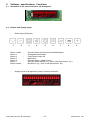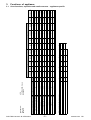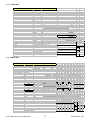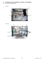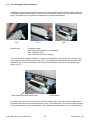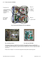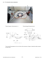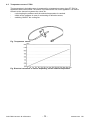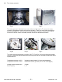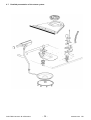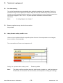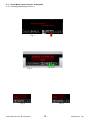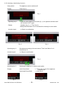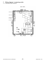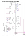
1
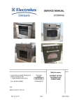
SERVICE MANUAL
COOKING
Steam oven
with Avantgarde
User Interface
© Electrolux Distriparts
Muggenhofer Straße 135
D-90429 Nürnberg
Germany
Fax +49 (0)911 323 1022
DGS-TDS-N
Edition:
05.09
Publ.-Nr.:
599 523 463
685
EN
Table of contents
1.
ESD=electrostatic discharge .............................................................................................. 3
2.
2.1
2.2
2.3
2.3.1
2.3.2
Software specifications, Functions ..................................................................................... 4
Illustration of the input electronics (UI) Avantgarde .............................................................. 4
Button / and display layout ................................................................................................... 4
Main features of operation ................................................................................................... 5
Clock setting following network reset .................................................................................. 5
Electronic child-safe function .............................................................................................. 5
3.
3.1
3.2
3.3
Functions of appliance ........................................................................................................ 6
Oven functions, capacities and small consumer - appliance-specific ............................... 6
Steam wet ........................................................................................................................... 7
Steam hot ............................................................................................................................ 7
4.
4.1
4.2
4.3
4.4
4.5
4.6
4.7
Component data, installation situation, dismantling ............................................................. 8
View of the open appliance .................................................................................................. 8
The Avantgarde input electronics ........................................................................................ 9
Power electronic OVC2000 ............................................................................................... 10
The thermal cutouts (actuators) ........................................................................................ 11
Temperature sensor PT500 .............................................................................................. 12
The steam generator ......................................................................................................... 13
Detailed presentation of the steam system ....................................................................... 14
5.
5.1
5.2
5.3
5.4
Technical equipment ......................................................................................................... 15
Fan after-running ............................................................................................................... 15
Measure against wrong electrical connection ................................................................... 15
Safety function safety cutoff of oven .................................................................................. 15
Temperature safety device ................................................................................................ 16
6.
6.1
6.2
6.2.1
6.2.2
Fault diagnosis/ What to do if ...? ...................................................................................... 17
Alarmmanagement (Faultcodes) ....................................................................................... 17
Demo Mode input electronic Avantgarde ........................................................................... 17
Activating/deactivating Version a ....................................................................................... 17
Activating / deactivating Version b ..................................................................................... 18
7.
7.1
7.2
7.3
Wiring diagram / measuring points ................................................................................... 19
Connection Point Overview ............................................................................................... 19
Example circuit diagram steam oven with Avantgarde UI (B9820-4) ................................ 20
Operative Equipment Overview ......................................................................................... 21
Changes .......................................................................................................................................... 22
DGS-TDS-N 05.09 A. B. © Electrolux
-2-
599 523 463
EN
1.
ESD=electrostatic discharge
As the single electronic interfaces are not protected internally against statical electricity and are
partially open, you must pay attention to that, in case of a repair, there will be a potential
compensation via the housing of the appliance (touch it) in order to neutralize a possible charging
and to prevent a damaging of the affected electronic interface.
You also have to be careful with those electronics delivered as spare parts, which have to be put
out of the ESD protective package only after a potential compensation (discharge of possible
statical electricity).
If a potential compensation with an existing static electricity is not executed, it does not mean that
the electronic is demaged directly. Consequential damages may result due to the damaging of
internal structures which arise only in case of load through temperature and current.
Endangered are all assembly groups which are provided with control entries, wire paths lying open
and free-accessible processors.
DGS-TDS-N 05.09 A. B. © Electrolux
-3-
599 523 463
EN
2.
Software specifications, Functions
2.1
Illustration of the input electronics (UI) Avantgarde
2.2
Button / and display layout
-
Button layout (Example)
1
2
Button 1 and 2
Button 3
Button 4
Button 5
Button 6
Button 7
Button 8 and 9
-
3
-
4
5
6
7
8
9
Selection button Ovenfunction forward/backward
Avantgarde menuebutton
Confirmation button OK
Main button
Selection button - Quick Heating
Selection button MODE (e.g., clock, meat thermometer, etc.)
Minus/Plus (e.g., clock, meat thermometer, etc.)
display layouts of all appliance groups, countries and brand
DGS-TDS-N 05.09 A. B. © Electrolux
-4-
599 523 463
EN
2.3 Main features of operation
2.3.1 Clock setting following network reset
Information: The oven only functions with set time!
When the appliance must be connected again with the mains e.g. after a repair, you have to set the
clock anew. Proceed as follows:
a)
b)
c)
Following connection or a power loss the symbol for the time of day blinks.
With the +/- buttons set the time of day.
If need be, confirm with the MODE button (=Timer button) The appliance is ready for
operation.
2.3.2 Electronic child-safe function
Basic prerequisites:
-
Power supply voltage is connected
No oven function selected.
If the appliance is equipped with a Main Switch, then this must be
activated
To activate and deactivate the child-safety function, the MODE button (=Timer button) must be
activated together with the „„Minus“ button.
Caution: the child-proof lock remains activated even when there is a voltage drop.
DGS-TDS-N 05.09 A. B. © Electrolux
-5-
599 523 463
EN
DGS-TDS-N 05.09 A. B. © Electrolux
-6-
High-speed heating (Boost) manuell
oven function
Pos.0 (Appliance switched off)
Pos.1 Steam cooking (wet)
Pos.2 Steam cooking (intense)
Pos.3 Steam cooking (hot)
Pos.4
Pos.5
Pos.6 (Upper/Lower heat)
Pos.7
Pos.8
Pos.9
Pos.10 (keep warm)
Pos.11
Pos.12
Pos.13
Electronic:
Oven class
Brand / Market:
C
D
E
B
A
B
A
-
96
110
180
150
200
200
180
230
230
80
30
150
120/80
A
B
C
D
E
Boost
suggested temperature
AEG
AVANTGARDE - Steam
OVC2000
X
X
X
X
-
grill
element
1900
X
X
X
X
X
X
X
X
X
X
X
X
X
X
X
X
X
X
X
X
X
X
X
X
X
X
X
X
heating elements (W)
top
bottom
rear
element element element
1000
1000
1900
X
X
X
X
X
X
-
Steam
generator
1500
X
X
X
X
X
X
X
X
X
X
cooking
fan
40
X
X
X
X
X
X
X
X
X
X
X
X
X
X
X
X
X
X
X
X
X
X
X
X
X
small loads (W)
cooling
oven lamp
fan
back wall
25
25
X
X
X
X
X
X
X
X
X
X
X
X
X
2630
2630
2630
3030
3030
2090
3030
2990
1990
2090
105
1090
3030
11,4
11,4
11,4
13,2
13,2
9,1
13,2
13,0
8,7
9,1
0,5
4,7
13,2
oven lamp
current
lateral
Power (W) ampere (W)
25
3.
Functions of appliance
3.1
Oven functions, capacities and small consumer - appliance-specific
599 523 463
EN
3.2
Steam wet
Steam wet
Elements temperature controlled:
steam element
Elements switched on:
cooking fan
cooling fan
light
actuator exhauste
actuator desteam
Temperature:
steam element controlled with 2. temp. sensor (offset -23°C)
Time:
default
changeable
indication
96°C
50° - 96°C (50-95 step 5 and 96°C)
yes
temperature
set temp. = sensor + offset
default
changeable
indication
30 min.
between 6 min. and dur_max
yes
BK02
DUR (Process time)
5 Min.
Specials:
exhaust activated DUR minus 5 min.
desteam activated last 5 min. (without exhaust)
2
1
Cooling fan speed
steam element off last 5 min.
3.3
Steam hot
Steam hot
Elements temperature controlled:
steam element
ring element
Elements switched on: cooking fan
cooling fan
light
actuator exhauste
actuator desteam
Toven < 110 °C
Temperature:
ring element:
BS01
power controlled 25% timecycle (non ring)
temperature controlled with 2. temp. sensor
max. temperature 96°C (+ offset = 78°C)
offset -18°C
power controlled 75% timecycle (non steam)
temperature controlled with oven temp. Sensor
temperature
set temp. = sensor + offset
default
changeable
indication
180°C
50° - max.
yes
steam element:
BK02
Toven > 110 °
DUR (Process time)
2 Min.
Specials:
10 Min.
exhaust activated DUR minus 2 min.
desteam activated last 2 min. (without exhaust)
2
1
Cooling fan speed
DGS-TDS-N 05.09 A. B. © Electrolux
-7-
599 523 463
EN
4.
Component data, installation situation, dismantling
4.1
View of the open appliance
Top view
1
2
5
4
3
Rear view
6
7
11
8
9
10
DGS-TDS-N 05.09 A. B. © Electrolux
-8-
599 523 463
EN
4.2
The Avantgarde input electronics
In addition to diverse semi-conductor modules, the Avantgarde input electronics mainly includes a
LCD display and a microprocessor. This controls the electronic control unit via a personalised program. The required oven functions are entered via a so-called touchboard.
Fig. 1
Electric data:
Fig. 2
-
Fig. 3
5V supply voltage
Operating current 50mA for the electronic
max. 110mA for LCD
max. 150mA for touch incl. Lighting
The user interface is positioned firmly in a plastic housing (E-box). The whole unit is locked in the
panel support. After pressing in the notch (Fig. 1) and drawing it afterwards to the right side of the
appliance (Fig. 2), the user interface can be removed backward, in direction of the appliance's
interior (Fig. 3).
Touch board stuck with switch panel
Foil conductor
At works the touch board is stuck directly onto the switch panel. Even in the need of replacement
the switch panel and the touch board form one unit. It is provided with nine sensors which transmit
the received impulses to the user interface. This happens via a data link in form of a foil conductor.
DGS-TDS-N 05.09 A. B. © Electrolux
-9-
599 523 463
EN
4.3
Power electronic OVC2000
Connections for
Relay for
- meat thermometer
- door lock
- Temperature sensor
- door lock
- telescopic bars
- data link
- lighting
- fan, moto
Power supply
Relay for
50....60Hz
230V AC
- all-pole cutoff
Fig.: Powerboard OVC2000 wired in the appliance
Fig.: assembly situation
Fig.: Spare part OVC2000
The power electronics are located on the rear side of the appliance and are accessible after
removing the housing rear panel. The power board is installed in a so-called „functions box“ made
of plastic. These two components, power electronics and plastic box, are also a replacement part
unit (see Ill.)
Please refer to Chapter 7 for connection designations and possible measuring points.
DGS-TDS-N 05.09 A. B. © Electrolux
- 10 -
599 523 463
EN
4.4
The thermal cutouts (actuators)
1
2
Thermal trigger cooking steams (1)
Thermal trigger Devaporizing (2)
ON OFF
Time
Time
OFF ON
HUB
HUB
ON
ON
OFF
OFF
The nominal lifting distance is 6 mm for both of the actuators. Chapter 3 describes which actuator
is active when.
DGS-TDS-N 05.09 A. B. © Electrolux
- 11 -
599 523 463
EN
4.5
Temperature sensor PT500
The temperature in the baking oven is measured by a temperature sensor (type PT 500) for
appliances with control board. The sensor is provided at the rear of the appliance. It is used to
transmit to the electronic systems the values for:
cyclic heating the radiators until the selected temperature is reached;
switch off the radiators in case of overheating of defective sensor;
switching ON/OFF the cooling fan.
Fig. Temperature sensor
Fig. Electrical resistance of sensor depending on the ambient temperature
DGS-TDS-N 05.09 A. B. © Electrolux
- 12 -
599 523 463
EN
4.6
The steam generator
Fig. 1
Fig. 2
The steam generator is siutated in the centre of the oven floor (fig. 1). To remove the steam
generator, the appliance must be laid onto the side panel. There is a cover on the housing floor
(service opening, fig. 2), which is screwed in position with six screws. These screws must be
loosened in order to access the steam generator and the two temperature sensors.
Fig. 3
Fig. 4
Fig. 5
The steam generator/temperature controller 120/170°C unit (figs. 3/4) is held with eight hexagon
nuts (fig. 5) which must be loosened before the component can be removed in the direction of the
appliance interior.
Temperature controller 120°C Temperature controller 170°C -
Signal tone lack of water (f3.2 in the circuit diagram)
Deactivation steam generator (f3.1 in the circuit digram)
Heating element performance
Water capacity
1500W
0,7l
DGS-TDS-N 05.09 A. B. © Electrolux
- 13 -
599 523 463
EN
4.7
Detailed presentation of the steam system
DGS-TDS-N 05.09 A. B. © Electrolux
- 14 -
599 523 463
EN
5.
Technical equipment
5.1
Fan after-running
The cooling fan switches on automatically when putting the appliance into operation. First it is in
operation to keep cool the appliance surfaces. After the oven was switched off, the fan continues
running to cool the appliance and then switches off automatically at a centre of gravity temperature
of the muffle of approx. 120°C-130°C. The post-operative ventilation is controlled via the
electronics.
Note:
5.2
-
for wiring diagram see chapter 7
Measure against wrong electrical connection
Not provided.
5.3
Safety function safety cutoff of oven
If the oven is not switched off after a specific period of time or if the temperature is not changed,
then it switches off automatically.
The oven switches off at an oven temperature of:
Putting into operation after a safety cutoff:
Note:
Press any button
The safety cutoff is cancelled, when the clock function „duration“ or „end“ has been set.
Furthermore, it is not active with the functions, low-temperature cooking (bio cooking).
DGS-TDS-N 05.09 A. B. © Electrolux
- 15 -
599 523 463
EN
5.4
Temperature safety device
temperature safety device
The double temperature fuse which deactivates all of the pols in case of overheating is situated
next to the OVC2000 powerboard. The measured temperature value upon deactivation amounts to
220°C (f2.1 and f2.2 in the circuit diagram).
DGS-TDS-N 05.09 A. B. © Electrolux
- 16 -
599 523 463
EN
6.
Fault diagnosis/ What to do if ...?
6.1
Alarmmanagement (Faultcodes)
Alarmmanagement Powerboards Prisma, OVC1000 und OVC2000
Display
F0
F1
F2
F3
F94
F4
F5
F95
F96
F6
F7
F8
F9
F10
F11
F91
F12
F13
F14
F15
F16
Description of fault
Fault repair
replace power electronics
Internal error
door cannot be locked
Test door locking system
door cannot be unlocked
Test door locking system and unlocking thermostat
f11
software error
Execute network reset by disconnecting the
appliance from the electricity supply and restarting
Temperature sensor alarm - resulting in F4
Test temperature sensor, replace if necessary
Temperature sensor without contact or short circuit Test temperature sensor, replace if necessary
Clotted heating element relay contacts on the
power electronics
Replace power electronics
Temperature alarm at power electronics - resulting Test built-in situation of the ventilation channel and
in F6
the function of the cooling fan
Temperature alarm at power electronics - resulting Test built-in situation of the ventilation channel and
in F6
the function of the cooling fan
Power electronics temperature too high
Test built-in situation of the ventilation channel and
the function of the cooling fan
Faulty electrical connection (only in appliances
Correctly connect the appliance and re-start
with Prisma power electronics)
No connection between power electronics and
Check connection line - replace electronic systems if
input electronics
necessary
Micro processor resets itself independently (=
Execute network reset by disconnecting the
Reset)
appliance from the electricity supply and restarting
Triac on power electronics defect
Activate Main Button, select an operation modus
with hot air, wait for cooling ventilation start, replace
power electronics again in the event of an error report
following approximately 20 seconds
Meat skewer sensor without contact or shortCheck meat thermometer, also check bushing and
circuited
wiring if necessary; if all this OK replace power
electronics
Temperature sensor alarm for steam generator Test temperature sensor, replace if necessary
resulting in F12
Temperature sensor of steam generator without
Test temperature sensor, replace if necessary
contact or short-circuited
Internal electronics error
Replace power electronics
software error
Replace input electronics
Internal electronics error
Replace input electronics
Combined alarm Pyrolytic cleaning/cooking zone Replace input electronics
6.2 Demo Mode input electronic Avantgarde
6.2.1 Activating/deactivating Version a
Disconnect appliance approx. 10 sec from the supply mains. After the renewed connection „time of
day“ is lit, the display indicates „12.00“ . Now actuate the „selection“ key, afterwards activate the
demo mode by pressing together with the „selection“ and „minus“ key simultaneously within 2 sec.
For deactivating the demo mode please proceed in the same order.
The active demo Mode is confirmed by the time symbol in the display. When activating the Demo
Mode, please make a mental note of the positions of the „Selection“ and „Minus“ keys as these
have to be pressed once more in order to deactivate the Demo Mode but it is possible that these
arte not visible, depending on the date of manufacture and software version.
DGS-TDS-N 05.09 A. B. © Electrolux
- 17 -
599 523 463
EN
6.2 Demo Mode input electronic Avantgarde
6.2.1 Activating/deactivating Version a
OBER-/UNTERHITZE
Sprache einstellen /
Language Menu
Fig. 1
Fig. 2
Fig. 3
DGS-TDS-N 05.09 A. B. © Electrolux
Fig. 4
- 18 -
599 523 463
EN
6.2.2 Activating / deactivating Version b
Start position:
The appliance must be switched off.
Display:
"Time" (fig. 1).
Fig. 1
Operating step 1:
Press the main switch for 5 seconds (fig. 1), the appliance switches itself
"ON" and then "OFF" again.
Display:
"Standby" (fig. 2) ---> "Time" (fig. 3).
Background illumination for 10 seconds after releasing the main switch.
Acoustic signal:
1x "Beep" as confirmation.
Fig. 2
Fig. 3
Operating step 2:
Simultaneous pressing of the two buttons "Timer" and "Minus" for 2
seconds (fig. 4).
Acoustic signal:
3 x "Beep" as confirmation.
Fig. 4
Operating step 3:
Switching the appliance on with the main switch
Display:
active Demo Mode
deactivated Demo Mode
Fig. 5
DGS-TDS-N 05.09 A. B. © Electrolux
---> "Time" (fig. 5), even if the appliance
is switched off.
---> none (fig. 6)
Fig. 6
- 19 -
599 523 463
EN
7.
Wiring diagram / measuring points
7.1
Connection Point Overview
DGS-TDS-N 05.09 A. B. © Electrolux
- 20 -
599 523 463
EN
7.2
Example circuit diagram steam oven with Avantgarde UI (B9820-4)
DGS-TDS-N 05.09 A. B. © Electrolux
- 21 -
599 523 463
EN
7.3
Operative Equipment Overview
DGS-TDS-N 05.09 A. B. © Electrolux
- 22 -
599 523 463
EN
Changes
Pages
17,
Chapter 6.1
DGS-TDS-N 05.09 A. B. © Electrolux
changed
- 23 -
599 523 463
EN