1
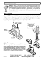
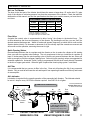
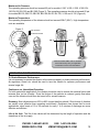
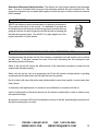
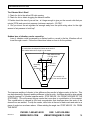
Pneumatic Ball
Mounting Instructions • Operating Instructions •Technical Data
Parts List • Troubleshooting
HQ & Factory:
75 Stilson Road
Wyoming, RI 02898
Canada:
2215 Dunwin Drive
Mississauga, ONT L5L 1X1
E-mail: [email protected]
Phone: 800 633-0032
(401) 539-2392
Fax: (401) 539-2584
E-mail: [email protected]
Phone: 800 465-9709
905-828-4191
Fax: 905-828-5015
Thank you for choosing VIBCO, Inc. for your vibration needs. You are now the owner of the
finest pneumatic piston vibrator available today, backed by complete manufacturer confidence in
its quality and dependability. For reference, please complete the information below about your
new VIBCO vibrator.
Model Number:
____________________
Date of Purchase: ____________________
TABLE OF CONTENTS
Safety Instructions & How It Works...............................................................................................3
Mounting Instructions Checklist.................................................................................................4-5
Mounting Suggestions by Bin Type............................................................................................6-9
Custom Mounting.........................................................................................................................9
Vibrator Installation & Pneumatic Hook-up............................................................................10-12
Operating & Maintenance Instructions...................................................................................12-13
Troubleshooting..........................................................................................................................14
Technical Data & Dimensions
Model BB.........................................................................................................................15
Model BV......................... ................................................................................................16
Model V...........................................................................................................................17
Parts List & Breakdown
Model BB .........................................................................................................................18
Model BV .........................................................................................................................19
Model V...........................................................................................................................20
Parts List..........................................................................................................................21
Warranty & General Information.................................................................................................21
REV295-13
PHONE: 1-800-633-0032
FAX: 1-401-539-2584
WWW.VIBCO.COM
[email protected]
2
SAFETY INSTRUCTIONS
WARNING: Failure to read and follow these installation instructions and safety
precautions could result in personal injury, equipment damage, shortened service
life or unsatisfactory equipment performance. All information in this document is
vital to the proper installation and operation of the equipment. It is important that
all personnel who will be coming in contact with this product thoroughly read and
understand this manual.
HOW IT WORKS
Your new VIBCO pneumatic ball vibrator uses compressed air to drive a hardened steel ball
at high speeds around a ground and polished race, creating high frequency vibration. The use
of o-rings has been eliminated in order to allow each unit to be used in environments where
temperatures can reach up to 350º F. The movement of the steel ball in the vibrator is controllable
by regulating the incoming applied air pressure or adjusting the muffler.
AIR FLOW
Thank You for
choosing VIBCO
Vibrators
BALL
RACE
Optional Features:
VIBCO pneumatic ball vibrators are available in many
different configurations.
Your ball vibrator can be
custom made to include features that will accommodate
environments where absolute cleanliness is desired. All
models are equipped with an exhaust port to lead away
the exhausted air from areas where cleanliness is a must
Contact VIBCO if you would like more information.
REV295-13
PHONE: 1-800-633-0032
FAX: 1-401-539-2584
WWW.VIBCO.COM
[email protected]
3
MOUNTING INSTRUCTION CHECKLIST
Warranty is void if vibrator is not properly installed. During installation follow and check off the
following steps and your vibrator should provide you with years of trouble-free service.
□ Determine the length of the channel iron.
□ Select thickness of vibrator mounting plate and method of mounting.
□ STITCH weld mounting plate to channel iron.
□ Determine where vibrator should be placed on the bin.
□ STITCH weld channel iron to bin.
□ Place vibrator on mounting plate. It is important that you check the
mounting plate for any warping. Secure vibrator firmly.
□ Install safety chain or wire.
□ Connecting pneumatics.
□ Continuous vs. intermittent operation.
□ FILL OUT WARRANTY CARD!!!
MOUNTING INSTRUCTIONS
Mounting Plate
For force up to 100 lbs. use a 1/4 in. thick plate, 100 to 500 lbs.
use a 3/8 in. to 1/2 in. thick plate and over 500 lbs. use a 1/2 in.
thick plate. (See Table).
CORRECT MOUNTING PLATES
LBS. OF FORCE
PLATE THICKNESS
up to 100 lbs.
1/4” plate
100 to 500 lbs.
3/8” to 1/2” plate
over 500 lbs.
1/2” plate
Mounting Channel
Never place the vibrator directly onto the skin of the bin. It should be mounted to a plate and piece of
channel iron that has been welded to the bin. The proper mounting method is to use either 3 in. or 4 in.
channel iron. This will help to stiffen the structure to be vibrated as well as spread the vibration over a
larger surface, increasing the overall efficiency and diminishing the possibilities of fatigue cracks in the
bin material.
VIBRATOR
MNTNG PLATE CHANNEL IRON FACTOR
FORCE in LBS THICKNESS
SIZE
A
101 - 500
1/4" - 3/8"
3" x 4.1 lbs
3" x 5 lbs
2
501- 1200
1/2"
4" x 5.4 lbs
4" x 7.5 lbs
3
1. Longer channel iron will not affect vibrator
performance, but total channel length should not
exceed length of bin wall.
BIN WALL FACTOR
THICKNESS
B
1/8" (10 ga.)
or less
1/8" - 1/4"
6
5
1/4" - 3/8"
4
3/8" - 1/2"
3
1/2" & up
2
2. Percentages shown indicate % of bin wall height your channel iron
should be for shorter bins.
FACTOR USE CH. IRON
A+B
LENGTH
9
5 - 7 FT.
(70 -80%)
8
4 - 6 FT.
(60 - 70%)
7
3 - 5 FT.
(50 - 60%)
6
2 - 4 FT.
(50 - 60%)
5
1 - 2 FT.
(50 - 60%)
4
N/A
3. To match your vibrator on chart above, model number suffixes generally correspond to pounds of
force generated. For any questions, consult VIBCO.
REV295-13
PHONE: 1-800-633-0032
FAX: 1-401-539-2584
WWW.VIBCO.COM
[email protected]
4
Welding Mounting Plate to Channel Iron
Weld the mounting plate to the middle of the channel iron. If the bin plate is 3/16 in. or less, weld
the mounting plate to the back of the channel iron (see figure 3 or 4). If the bin plate is over 3/16
in. weld the mounting plate to the legs of the channel iron (see figure 1). Drill and tap holes or
use studded plate (see figure 1).Make sure the mounting plate does not warp or distort. If this
occurs, straighten, replace it or shim up vibrator.
Different Suggestions for Mounting the Channel
1. Mounting plate welded to legs of channel iron.
2. Channel iron with holes drilled thru and nuts welded on back side, or
just holes drilled thru.
3. Add mounting plate and drill and tap holes thru.
4. Weld studs to back of channel.
Always stop welds 1 in. from ends to prevent cracks.
1
2
3a
3b
4
NOTE: for a list of alternate and special application brackets, see pg. 35 of the VIBCO General Catalog.
Placement
For coarse materials the vibrator should be mounted approximately 1/3 of the distance from
the discharge opening to the top of the sloped portion of the bin. For fine grain materials place
the vibrator approximately 1/4 of the same distance (see different mounting suggestions on the
following pages).
Welding Channel Iron To Bin
Where possible the mounting plate on the channel iron should be placed 1/3 to 1/4 of the distance
from the discharge opening to the top of the sloped portion of the bin. Stitch weld channel iron
in place, then weld intermittent welds 3 to 6” long with 3” between them along the entire length
of the channel. Stop weld a minimum of 1” from the ends, it is important that you do not weld
the ends of the channel iron. The heat concentration when welding the ends could cause the
beginning of fatigue cracks.
Installing Safety Chain
It is important to install a safety chain or wire in order to prevent the vibrator from falling and
potentially causing injury if it comes loose from its mount.
REV295-13
PHONE: 1-800-633-0032
FAX: 1-401-539-2584
WWW.VIBCO.COM
[email protected]
5
MOUNTING SUGGESTIONS
1/2 Rectangular Bin
Two Vibrators On
A Single Bin
Rectangular Bin
1/
3L
L
L
1/2
1/
4
L to 1/
1/
4t
o1
L
/3
L
3L
1/4
to
1/3
L
L
Conical Bin
One Vibrator for a Double Bin
4 in. Channel
3/8” Gussets
4 in. Square Tubing
Vibrator
Mounting Plate
Angle Iron Stiffeners
Instead of Channel Iron
REV295-13
Bin with Stiffeners
Thin Skinned Bin
Corner Mount
PHONE: 1-800-633-0032
FAX: 1-401-539-2584
WWW.VIBCO.COM
[email protected]
6
Sheet Metal Bin
Belt Conveyor &
Standard Bin
Drill Holes
To Match
Bolt Pattern
On Bin
Bolt To Bin
L
1/3 L
Weld Both
Sides
Of Angle
Iron
Angle Iron Feet
3/8 in. Mounting Plate
W
1/3 W
L
1/3 L
Belt Conveyors
Belt conveyor feeds from the front.
Vibrator should be placed 1/3 from
the front. If 2 vibrators are used,
place second one directly opposite
1/3 from the back. Do not operate
back vibrator until bin is empty in front
and the front vibrator has turned off.
For more details, consult VIBCO.
W
FLO
L
Long Bin
1/3 L
W
1/3 W
L
1/3 L
REV295-13
Screw Conveyors
Feeds from back. Vibrator should be
placed 1/3 from the back. If 2 vibrators
are used, place 2nd one directly opposite
1/3 from the front. Do not operate front
vibrator until bin is empty in back and the
back vibrator has turned off. For more
details, consult VIBCO.
PHONE: 1-800-633-0032
FAX: 1-401-539-2584
WWW.VIBCO.COM
[email protected]
7
Heat Mounts for Insulated Bins Containing High Temperature Materials: When materials in
the bin have a temperature over 150oF, it is advisable to use a “heat” mount to prevent excessive
heat from reaching the vibrator and causing overload or bearing failure. Also, ask for “high”
temperature grease in vibrator bearing. Consult VIBCO for vibrator size.
BIN
2-1/2 to 3ft
2ft
1-1/2ft
1ft
10 IN.
CHANNEL
450°-500°F
8 IN.
300°F
6 IN.
200°F
140°F
4 IN.
L
1/3 L
CHANNEL IRON
3” OR 4” CHANNEL IRON
GUSSETS
GUSSET
L
4” PIPE, I-BEAM OR TUBE
PLATE
VIBRATOR
1/4 L
Concrete Bin: Mount steel plate on inside of
bin so that the vibrator sits 1/3 up bin side.
Isolate the plate from the concrete by using
vibration shock absorbers. Consult VIBCO for
detailed drawings.
Wood Bin: Use steel plate on inside and bolt
to outside mounting channel.
RUBBER
PLATE
PLATE
SPACER
RUBBER
REV295-13
PHONE: 1-800-633-0032
FAX: 1-401-539-2584
WWW.VIBCO.COM
[email protected]
8
Chutes: In order to successfully move material in a chute, the “angle of repose” of the material
has to be known. It can be found in most handbooks or can easily be measured by pouring a cup
of the material on a table. The angle between the table and the cone the material makes is the
“angle of repose”. To move the material in the chute, it should be inclined no less than 1/2 of the
“angle of repose” If this cannot be obtained, a feeder is necessary to move the material.
For optimum performance follow these guidelines:
• Force (impact) needed on vibrator is equal to weight of chute + vibrator + max material
in chute.
• Chutes must have an inclination of at least 15o for vibrators to be able to move the
material. If inclination is less the chute has to be made into a feeder. Contact VIBCO for
selecting the proper size vibrator or ask for the bulletin covering chutes.
• Chutes up to 6 ft. are generally handled by one vibrator mounted approximately 1/3 from
the discharge.
• On chutes over 6 ft. long, two vibrators are needed, one should be placed 18 - 24
inches from the discharge. The other approximately in the middle. Since chutes are
very sensitive to vibration, provision should be made to move the lower vibrator 6 inches
in either direction. This could mean the difference between moving the material or not
moving it.
L = Up to 6 FT.
1/3 L
CUSTOM MOUNTING APPLICATIONS
VIBCO’s application specialists can provide general instructions and guidelines for the
installation of VIBCO vibrators on customer equipment. These instructions and guidelines are
based on the industries best practices and years of experience in applying vibrators. VIBCO
specialists are available to review a customer’s individual application to verify installation and
make recommendations. These recommendations should not be considered as the Welding
Procedure Specifications for the installation.
If Welding Procedure Specifications are required, they should be provided by a professional
engineer who is familiar with the structure, the vibrator being mounted, as well as all of the
specifications of the materials being used and any of the environmental details present at the
application.
For more custom mounting applications call, email or fax.
REV295-13
PHONE: 1-800-633-0032
FAX: 1-401-539-2584
WWW.VIBCO.COM
[email protected]
9
VIBRATOR INSTALLATION
Installation of the Vibrator
It is now time to put the VIBCO vibrator in place. Make sure that it is secured tightly. Retighten
the bolts after the first 10 to 15 minutes of operation and check them periodically to maintain
proper tightness (figures 1 and 2).
Damage to the bin and the vibrator can occur if not mounted securely.
Figure 1
Angle Iron
June
Channel Iron
July
REMEMBER
check those
bolts!
August
Figure 2
REV295-13
PHONE: 1-800-633-0032
FAX: 1-401-539-2584
WWW.VIBCO.COM
[email protected]
10
PNEUMATIC HOOK-UP
Air Line To Vibrator
The hose to the inlet port of the vibrator should have the same or larger hose I.D. as the inlet I.D. (pipe
size) of the vibrator to minimize pressure loss from the compressor to the vibrator. Check the technical
data section of this manual, and find the specifications that meet your model to ensure you have the correct sizes.
TO DETERMINE CORRECT AIR HOSE SIZE**
BALL MODEL
NUMBER
MIN AIR
HOSE DIA
MIN FRL*
THREAD DIA
CFM
100-130
1/8”
1/4”
4-6
160-250
1/4”
1/4”
7 - 10
320-380
3/8”
3/8”
10 - 20
*F=filter R=regulator L=lubricator
**these for installation of single unit;
for multiple units adjust to maintain CFM
Flow Valve
A simple flow control valve is recommended to allow “tuning” the vibrator to the desired force. The
air flow determines the force and frequency of the vibrator. By throttling the air flow, you can “find” the
desired material discharge rate. Watch for and avoid speeds (frequency) at which the bin wall and the
vibrator shake violently. An increase or decrease of air flow usually stops the excessive movement and
will smooth out the operation, assuming the mount is rigid.
Quick Opening Valves
Recommended between the air regulator and the vibrator so the air enters the vibrator at full starting
force even with low regulator valve settings. The only requirement is that you install the air regulator at
least 12 inches away from the quick opening valve so that the air pressure between the two valves will
build up enough to yield the necessary starting force. Solenoid (quick opening) valves are suggested for
automatic operations. Automatic Timed Cycling is programmed with the timer usually directly connected
to the bin or hopper gate switch. When the gate is opened the timed cycling system is activated.
Air Filter
It is recommended that you use an air filter in the line. Clean air will prolong the life of any pneumatic
vibrator. Dirty or moist air will harm the unit and impair it from operating at maximum efficiency and lowest
air consumption.
Air Lubricator
Lubrication is required for the smooth operation of the pneumatic ball vibrators. The lubricator should
be set at 1 drop for every 10 CFM the vibrator requires. Use SAE-10 oil or lighter.
To
Vibrator
Air
Regulator
Solenoid
Valve
To Gate
To Control
Switch
For best performance
DO NOT RUN vibrators
in series off one hose
LUBRICATION IS MANDATORY!
5’ solenoid to vibrator
Timer
Air
Filter
Flow
Valve
Air
Lubricator
Use SAE-10 or lighter oil
1 drop for every 10 cubic
ft/min (CFM) (available at any
industrial or auto supply store)
REV295-13
PHONE: 1-800-633-0032
FAX: 1-401-539-2584
WWW.VIBCO.COM
[email protected]
11
Maximum Air Pressure
The operating pressure should not exceed 80 psi for models V-190, V-250, V-320, V-380, BV190, BV-250, BV-320 and BV-380 (Figure 3). The operating pressure should not exceed 60 psi
for models BB-100, BB-130, BB-160, BB-190, BV-60, BV-130, V-100 and V-130 (Figure 4).
Maximum Temperature
The operating temperature of the vibrator should not exceed 200oF (93oC). High temperature
units are available.
Figure 3
Safe Operation
Not Recommended
350° F
175° C
Figure 4
Alternative HIGH TEMP units are available.
Consult the factory with your application
information for best recommendations.
OPERATING INSTRUCTIONS
To Obtain Maximum Performance
It is not necessary to operate the vibrator at its maximum capacity to obtain maximum performance.
Air regulators, timers, etc. should be used to tune the vibrator for optimum performance and
ensure longer life.
Continuous vs. Intermittent Operation
For bulk material bin applications, the vibrator should be used to reduce the material friction and
increase flow, not as a feeder. Once the friction of the particles is reduced, gravity flow takes
over and the vibrator should then be turned off for several reasons:
Economy. Most vibrators are run 60% to 80% longer than they should. Short bursts of vibration
are usually more effective than operating continuously. Experience has shown that for most
applications, short bursts of 10 to 30 seconds for every 1 to 5 minutes of discharge are more
effective and efficient.
Life of the Unit. The life of the vibrator will be determined by the length of operation and the
cleanliness of the air supply.
REV295-13
PHONE: 1-800-633-0032
FAX: 1-401-539-2584
WWW.VIBCO.COM
[email protected]
12
Guaranteed Success of the Application. The vibrator can only furnish material to the discharge
area. If more is furnished than conveyed, the remaining material will pack inside the bin. We
suggest the vibrators only run when the bin gates or doors are open, or when continuous material
flow is needed.
MAINTENANCE
VIBCO ball vibrators require maintenance for optimum performance.
They require lubrication in the air line. It is advisable to put both an
air-cleaner and an air lubricator in the line to prevent dust and dirt from
going through the unit and clogging the muffler as well as keeping the
ball and race properly oiled. Use a SAE-10 or light weight tool oil for
proper lubrication of a ball vibrator.
IMPORTANT CONSIDERATIONS FOR LONG OPERATING LIFE
Contaminated air will shorten the life of the vibrator considerably, and will clog the race on which
the ball runs. It will also increase the wear of the ball, increasing the air consumption and
diminishing vibrator efficiency.
Water in the air line will reduce the effectiveness of the lubrication necessary to make the unit
operate and lubricate properly.
Water, dirt and air line rust at air pressures over 80 psi will create a sludge similar to grinding
compound and will wear down the ball and the race very quickly.
No oil in the air will cause the piston and cylinder walls to wear down rapidly, in some cases less
than 8 hours.
In extremely cold applications it is advised to mix antifreeze or kerosene with the oil.
Inject a small quantity of kerosene directly into the vibrator occasionally in order to clean out any
accumulated sludge.
Air pressure in excess of 80 psi will increase the velocity of the ball, diminishing the protective oil
film and increasing the unit wear.
REV295-13
PHONE: 1-800-633-0032
FAX: 1-401-539-2584
WWW.VIBCO.COM
[email protected]
13
TROUBLESHOOTING
The Vibrator Won’t Start!
1. Check for dirt in the airline OR inlet opening
2. Check for dirt or debris clogging the exhaust muffler
3. Double check the size of your air line - is it large enough to give you the correct cubic feet per
minute (CFM) and correct air pressure (minimum required = 20 PSI)?
4. Did you mount the air regulator far enough away from the quick acting valve for the right
amount of air pressure to build up?
Sudden loss of vibration can be caused by:
Loss of vibration could be caused by a cracked weld or a crack in the bin. Vibration will not
travel through a crack. Follow the instructions below on how to fix the problem.
If cracks have developed, drill holes at the ends of
the cracks and weld on angle iron as shown
Stop welds at least
1 in. from ends
Mounting
plate
for vibrator
3 or 4 in.
channel
Do not weld 1 in.
from end of stiffener
The improper welding of vibrator to bin stiffeners often results in fatigue cracks in the bin. This
can be prevented by properly welding stiffeners to the bin side. A stiffener should be skip welded
to the bin leaving 3 to 4 inches between welds. STOP WELDS 1 IN. FROM THE ENDS OF THE
STIFFENER. This will prevent fatigue cracks that occur due to crystallization of the material.
This crystallization is caused by the heat concentration that develops when the ends of the
channel iron are welded. To stop the cracks, drill a hole at the end of each crack and weld on a
piece of angle iron as shown above. When welding the angle iron STOP WELDS 1 IN. FROM
THE ENDS.
REV295-13
PHONE: 1-800-633-0032
FAX: 1-401-539-2584
WWW.VIBCO.COM
[email protected]
14
Model BB Dimension and Technical Data
A
C*
L
MODEL
Inch/mm
Inch/mm
BB-100
1/2
5/16
8
BB-130
9/16 15
3/8
BB-160
5/8
16
BB-190
5/8
16
13
W
Inch/mm
H
Inch/mm
G
S
Inch/mm
INLET
OUTLET
Inch/mm
Inch/mm
NPT
NPT
40
3-1/4
83
2
51
5/16
8
1-1/8 29
1
26
1/8
1/8
10
1/15/16 49
3-3/4
96
2-1/4
58
5/16
8
1-1/4 32
1-3/16 31
1/4
1/4
3/8
10
2
50
4-1/8
105
2-9/16 66
3/8
10
1-1/2 39
1-1/4
32
1/4
1/4
3/8
10
2
50
4-1/8
105
2-9/16 66
3/8
10
1-1/2 39
1-1/4
32
1/4
1/4
1-9/16
Inch/mm
F
*Bolt Size
F
C
INLET
G
H
S
OUTLET
A
L
W
Weight
Model
oz
20 PSI
kg
VPM
40 PSI
CFM
60 PSI
VPM
CFM
VPM
Force
CFM
Max Lbs **
lbs
N
dB*
Material in Bin
BB-100
8
0.227
17000
2
20000
4
24000
6
55
245
75
550
BB-130
10
0.283
12000
2.5
15000
5
19000
7.5
80
356
72
800
BB-160
16
0.454
11000
3
13000
6
15000
8
140
623
76
1400
BB-190
18
0.510
10000
4
12000
7
15500
11
250
1112
77
2500
Data obtained on laboratory test block. Frequency and force will decrease on less rigid mount.
*Decibel from A-Scale at 1m.
**Rule of thumb for sizing “1 lb vibratory force to each 10 lbs of bin content”.
NOTE: Dimensions and data subject to change without notice.
REV295-13
PHONE: 1-800-633-0032
FAX: 1-401-539-2584
WWW.VIBCO.COM
[email protected]
15
Model BV Dimensions and Technical Data
Model
A
C*
L
W
H
F
G
R
INLET
OUTLET
Inch/mm
Inch/mm
Inch/mm
Inch/mm
Inch/mm
Inch/mm
Inch/mm
Inch/mm
NPT
NPT
BV-60
3
77
1/4
7
1-11/16
43
3-7/8
99
2-1/2
64
5/8
16
1-1/4
32
3/4
20
1/8
1/8
BV-130
4
102
3/8
10
1-15/16
49
4-7/8
124
2-3/4
70
3/4
20
1-7/19
37
7/8
23
1/8
1/4
BV-190
4
102
3/8
10
2-1/4
58
5-1/2
140
3-9/16
90
9/16
15
1-7/8
48
1-1/4
32
1/4
1/4
BV-250
5
128
1/2
13
2-7/16
62
6-3/4
172
3-15/16
100
7/8
23
2-3/16
56
1-5/16
33
1/4
1/4
BV-320
5
128
1/2
13
2-3/4
70
6-11/16
170
4-7/8
124
1-1/8
29
2-3/4
70
1-5/8
42
3/8
3/8
BV-380
6
153
5/8
16
2-15/16
75
7-7/8
201
5-3/4
147
1-1/8
29
2-13/16
72
2
51
3/8
3/8
*Bolt Size
G
INLET
OUTLET
H
C
F
A
R
L
W
Weight
20 PSI
Model
oz/lbs
BV-60
8 oz
0.227
kg
VPM
17000
BV-130
11 oz
0.312
12000
BV-190
24 oz
0.689
40 PSI
CFM
-
VPM
2
20000
2.5
15000
12000
60 PSI
CFM
4
VPM
80 PSI
CFM
24000
6
5
19000
7.5
10
14000
11
VPM
Force
CFM
-
16000
11
Max Lbs. **
lbs
N
dB
Material in Bin
55
245
75
550
80
356
76
800
260
1157
77
2600
BV-250
2.8 lbs
1.3
-
9200
8
10500
11
11000
13
380
1691
79
3800
BV-320
4.8 lbs
2.2
-
6500
9
7500
14
8400
17
480
2136
80
4800
BV-380
6.2 lbs
2.8
-
5500
10
6200
15
6500
20
600
2669
82
6000
Data obtained on laboratory test block. Frequency and force will decrease on less rigid mount.
*Decibel from A-Scale at 1m.
**Rule of thumb for sizing “1 lb vibratory force to each 10 lbs of bin content”.
NOTE: Dimensions and data subject to change without notice.
REV295-13
PHONE: 1-800-633-0032
FAX: 1-401-539-2584
WWW.VIBCO.COM
[email protected]
16
Model V Dimensions and Technical Data
Model
A
B
C*
L
W
H
G
K
R
INLET
OUTLET
inch/mm
inch/mm
inch/mm
inch/mm
inch/mm
inch/mm
inch/mm
inch/mm
inch/mm
NPT
NPT
V-100
3
77
-
1/4
7
1-11/16
43
3-7/8
99
2
51
11/16
18
-
3/4
20
1/8
1/8
V-130
4
102
-
3/8
10
1-15/16
49
4-7/8
124
2-5/16
59
11/16
17
-
15/16
24
1/8
1/8
V-190
4
102
-
3/8
10
2-3/16
56
5-1/16
129
3-3/16
81
7/8
23
2-5/8
67
1-5/16
34
1/4
1/4
V-250
4
102
-
1/2
13
2-7/16
62
5-9/16
142
3-1/2
89
1-1/16
27
2-15/16
75
1-1/2
39
1/4
1/4
V-320
4
102
-
1/2
13
2-3/4
70
5-9/16
142
4-7/8
124
1-3/8
35
4-1/8
105
1-1/2
39
3/8
3/8
V-380
5-1/2 140
1-1/4 32
3/8
10
2-15/16
75
6-7/8
175
4-7/8
124
1-3/8
35
3-7/8
99
2-3/8
61
3/8
3/8
*Bolt Size
L
INLET
G
K
H
OUTLET
C
A
W
Weight
Model
oz/lbs
20 PSI
kg
VPM
B
R
40 PSI
CFM
VPM
60 PSI
CFM
VPM
80 PSI
CFM
VPM
Force
CFM
lbs
Max Lbs**
N
dB*
Material in Bin
V-100
8 oz
0.227
18000
4
20000
6
24000
6
-
55
245
75
550
V-130
11 oz
0.312
10000
4
15000
5
19000
7.5
-
80
356
72
800
V-190
26 oz
0.737
-
12000
6
14000
10
16000
11
260
1157
73
2600
V-250
2.6 lbs
1.2
-
9200
8
10500
11
11000
13
380
1691
72
3800
V-320
4.6 lbs
2.1
-
7500
12
8900
14
10000
17
650
2892
78
6500
V-380
6.2 lbs
2.8
-
5500
10
6200
15
6500
20
600
2669
78
6000
Data obtained on laboratory test block. Frequency and force will decrease on less rigid mount.
*Decibel from A-Scale at 1m.
**Rule of thumb for sizing “1 lb vibratory force to each 10 lbs of bin content”.
NOTE: Dimensions and data subject to change without notice.
REV295-13
PHONE: 1-800-633-0032
FAX: 1-401-539-2584
WWW.VIBCO.COM
[email protected]
17
3
2
4
6
9
5
4
9
9
PHONE: 1-800-633-0032
FAX: 1-401-539-2584
WWW.VIBCO.COM
[email protected]
1
3
REV295-13
PNEUMATIC BALL
VIBRATOR:
MODEL BB SERIES
8
7
18
2
1
4
6
5
4
PHONE: 1-800-633-0032
FAX: 1-401-539-2584
WWW.VIBCO.COM
[email protected]
3
3
REV295-13
PNEUMATIC BALL
VIBRATOR:
BV SERIES
(BV-60, BV-130)
8
7
19
5
4
3
2
PHONE: 1-800-633-0032
FAX: 1-401-539-2584
WWW.VIBCO.COM
[email protected]
1
3
REV295-13
PNEUMATIC BALL
VIBRATOR:
BV SERIES
(BV-190, BV-250,
BV-320, BV-380)
7
6
20
2
1
5
7
6
5
4
PHONE: 1-800-633-0032
FAX: 1-401-539-2584
WWW.VIBCO.COM
[email protected]
3
4
REV295-13
PNEUMATIC BALL
VIBRATOR:
MODEL V SERIES
(V-100, V-130)
9
8
21
1
5
4
3
PHONE: 1-800-633-0032
FAX: 1-401-539-2584
WWW.VIBCO.COM
[email protected]
2
3
REV295-13
PNEUMATIC BALL
VIBRATOR:
MODEL V SERIES
(V-190, V-250,
V-320, V-380)
7
6
22
WARRANTY AND GENERAL INFORMATION
Warranty
All warranty claims must be submitted to VIBCO for approval prior to any repairs being done.
Failure to do so will void any and all warranty coverage.
Errors, Shortages and Complaints
Complaints concerning goods received or errors should be made at once. Claims must be made
within five days after receipt of goods. Clerical errors are subject to correction.
Returning Parts
Parts should not be returned to VIBCO without prior authorization. Call VIBCO’s customer service
department at 800-633-0032 (800-465-9709 in Canada) for a Return Goods Authorization (RGA)
number. A return authorization will be faxed to you. Return shipping must be prepaid. Material
returned may be subject to a 10% restocking fee. All returned shipments should clearly display
your name, address and original invoice number to ensure proper credit.
Orders for equipment built to specifications which vary from VIBCO’s standard units are not
returnable.
Responsibility
VIBCO cannot be responsible for delays due to strikes, accidents, negligence of carriers or other
causes beyond our control.
Freight Claims
Should you receive a shipment from VIBCO which was damaged in transit, file your claim with
the carrier immediately. All parts sold by VIBCO are on the basis of F.O.B. Wyoming, Rhode
Island.
Product Changes
VIBCO reserves the right to make changes in pattern, design or materials when deemed
necessary, without prior notice or obligation to make corresponding changes in previous
models.
Price Changes
Prices are subject to change without notice.
Ordering Spare Parts
Parts can be ordered through authorized distributors or directly from VIBCO. The following data
should be provided when ordering:
From foot of housing:
Model of unit.
From spare parts list:
Reference number, part number, description and quantity required.
Shipping instructions:
Specify shipping point and method of shipping.
REV295-13
PHONE: 1-800-633-0032
FAX: 1-401-539-2584
WWW.VIBCO.COM
[email protected]
23
www.vibco.com