1
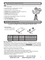
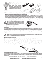
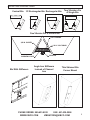
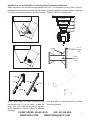
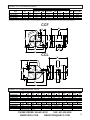
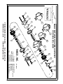
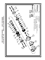
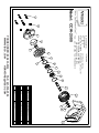
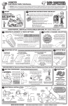
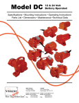
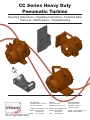
CC Series Heavy Duty Pneumatic Turbine Mounting Instructions • Operating Instructions • Technical Data Parts List • Maintenance • Troubleshooting Plus Field Offices: Southeast Regions Mid-Atlantic Regions Western Regions HQ & Factory: 75 Stilson Road, P.O. Box 8 Wyoming, RI 02898 Canada: 2215 Dunwin Drive Mississauga, ONT L5L 1X1 E-mail: [email protected] Phone: 401 539-2392 800 633-0032 Fax: 401-539-2584 E-mail: [email protected] Phone: 800 465-9709 E-mail: [email protected] 905-828-4191 Phone: 800-633-0032 Fax: 905-828-5015 Thank you for choosing VIBCO, Inc. for your vibration needs. You are now the owner of the finest silent pneumatic vibrator available today backed by complete manufacturer confidence in its quality and dependability. For reference please complete the information below about your new VIBCO vibrator. Model Number: ____________________ Date of Purchase:____________________ TABLE OF CONTENTS Safety Instructions .................................................................................................2 Mounting Instructions Checklist .............................................................................3 Mounting Procedures .........................................................................................3-4 Mounting To Bin Walls Or Chutes........................................................................5-8 Bolting Specifications & Pneumatic Hook-up.....................................................9-11 Operating Instructions & Matenence.....................................................................12 Troubleshooting....................................................................................................13 Bin Crack Repairs...........................................................................................13-14 Technical Data & Dimensions................................................................................15 Exploded Views & Parts List ...........................................................................16-23 Warranty & General Information ..........................................................................24 CAUTION These mounting instructions MUST be followed! Use of another manufacturers procedures may void warranty! PHONE ORDER: 800-633-0032 FAX: 401-539-2584 WWW.VIBCO.COM [email protected] 1 SAFETY INSTRUCTIONS WARNING: Failure to read and follow these installation instructions and safety precautions could result in personal injury, equipment damage, shortened service life or unsatisfactory equipment performance. All information in this document is vital to the proper installation and operation of the equipment. It is important that all personnel who will be coming in contact with this product thoroughly read and understand this manual. HOW IT WORKS VIBCO turbine air vibrators are designed to keep noise pollution at a minimum. Compressed air turns a specially designed turbine wheel, allowing the air to be channeled through the unit, then exhausting through muffler pads, making them virtually noiseless. These units require no lubrication and its oversized bearings give it years of trouble-free service. Models: CCF-2000; 4000; 5000; 7000 Foot Mount Type CCL-2000; 4000; 5000; 7000 Lug Type CCW-2000; 4000; 5000 Wedge Type General Features CCF models are the quiet solution for large bins, hoppers and chutes. Ideal for packing tables and screen applications. The lightweight and high force output, CCF-2000 and CCF-5000, replace noisy 3 in. and 4 in. piston vibrators. The CCF 7000 is ideal for precast and prestressed concrete and replaces loud roller vibrators. The portable CCL-2000 and CCL-4000 uses the LC-2 lug bracket. Its light weight makes it ideal for all small concrete precast forms. Model CCL-5000 and CCL-7000 with the LC-1 bracket are ideal for tables, casting concrete panels, window frames or replacing large piston vibrators on large bins. The CCW wedge type railcar vibrator series makes it easy to unload all of your load. Wether your unloading cement, flour, carbon black, bone black, aluminum shot, or chemical power the CCW can get the job done. Model CCW-2500 Hobo is the lightest railcar vibrator available for easy mobility and quick change over. CCF CCL CCW PERMANENT TWO HOLE FOOT MOUNT REMOVABLE LUG TYPE BRACKET MOUNT REMOVABLE WEDGE TYPE BRACKET MOUNT LC-1 LC-2 LUG BRACKET (PORTABLE IN CONJUNCTION) UWF-1 UWF-3 WEDGE BRACKET (PORTABLE IN CONJUNCTION) PHONE ORDER: 800-633-0032 FAX: 401-539-2584 WWW.VIBCO.COM [email protected] 2 MOUNTING INSTRUCTIONS CHECKLIST The warranty is void if vibrator is not properly installed. During installation follow and check off the following steps and your vibrator should provide you with years of troublefree service. o Determine style of mounting plate or bracket. o Determine length of channel iron. o Select method of mounting channel iron. o STITCH weld mounting plate or bracket to channel iron. o Determine vibrator placement on bin. o STITCH weld channel iron to bin. o Place vibrator on mounting plate. o Check the mounting plate for warping. Secure firmly. o Install safety chain or cable. o Connect pneumatics. o FILL OUT WARRANTY CARD!!!! NOTES ABOUT INSTALLATION If you have any questions consult the Mounting Instructions section of this manual or call VIBCO Technical Support at (800) 633-0032. Mounting Plate 1/2” thick for 2000 & 4000 5/8” thick for 5000 & 7000 or Thru Hole Force (lbs) Bin Thickness Channel Iron 2000 3/16 - 3/8 in. 4 in. 4000 1/2 in. 4 in. 5000 3/16 - 3/8 in. 4 in. 7000 1/2 - 5/8 in. 4 in. Studded Length 6 - 8 in. longer than vibrator 8 - 12 in. longer than vibrator 1 - 2 ft. longer than vibrator 8 - 12 in. longer than vibrator Mounting Channel Never place the vibrator directly onto the skin of the bin. It should be mounted to either a mounting plate or a piece of channel iron that has been stitch welded to the bin. The proper mounting method is to use channel iron. This will help to stiffen the structure to be vibrated as well as spread the vibration over a larger surface, increasing the overall efficiency and diminishing the possibilities of fatigue cracks in the bin material. Different Suggestions for Mounting the Channel 1)Mounting plate welded to legs of channel iron (see pictures below). 2) 4 in. channel with holes drilled thru and nuts welded on back , or just holes drilled thru. 3)Mounting channel with mounting plate and holes drilled or tapped thru. 4)Notch the channel for access to mounting bolts. 5)Weld studs to back of channel. PHONE ORDER: 800-633-0032 FAX: 401-539-2584 WWW.VIBCO.COM [email protected] 3 Stitch weld channel: weld 2 to 3 inches, skip 1 to 2 inches and repeat until securely mounted. Always stop welds 1 in. from ends to prevent heat concentration and bin cracking. 2 1 3 5 4 NOTE: for a list of alternate mounting brackets, see pages 35 & 36 of the VIBCO General Catalog. Welding Mounting Plate or Bracket to Channel Iron Stitch weld the mounting plate or bracket to the channel iron. If the bin plate is 3/16 in. or less, weld the mounting plate to the back of the channel iron (see Figure 2 or 4). If the bin plate is over 3/16 in. weld the mounting plate to the legs of the channel iron (see Figure 1). Drill and tap holes or use studded plate (see Figure 3). Make sure the mounting plate does not warp or distort. If this occurs, straighten it, replace it or shim vibrator. Note: No matter what thickness of plate used, plate can still warp due to welding heat and potentially crack foot mount if not welded per VIBCO instructions. (see example to right) Placement For coarse materials the vibrator should be mounted approximately 1/3 of the distance from the discharge opening to the top of the sloped portion of the bin. For fine materials place the vibrator approximately 1/4 of the same distance (see different mounting suggestions on the following pages). Note: For live bottom bins, mounting placement procedure is different. Please call VIBCO factory to speak with an application engineer. Welding Channel Iron to Bin Where possible, the mounting plate or the channel iron should be placed 1/3 of the distance from the discharge opening to the top of the sloped portion of the bin, for fine grain materials place 1/4 of the same distance. Tack weld channel iron in place, then weld intermittent welds 3 in. to 6 in. long with 3 in. between them along the entire length of the channel. Stop weld a minimum of 1 in. from the ends. It is important that you do not weld the ends of the channel iron. The heat concentration when welding the ends could cause premature fatigue cracks in the bin wall. Installing Safety Chain or Cable It is important to install a safety chain or wire to prevent the vibrator from falling and causing injury if it comes loose from its mount. Attach chain to stationary object, not to mounting plate or channel iron. PHONE ORDER: 800-633-0032 FAX: 401-539-2584 WWW.VIBCO.COM [email protected] 4 MOUNTING SUGGESTIONS 1/2 Rectangular Bin Rectangular Bin Two Vibrators On A Single Bin Conical Bin One Vibrator For A Double Bin Bin With Stiffeners Angle Iron Stiffeners Instead of Channel Iron Thin Skinned Bin Corner Mount PHONE ORDER: 800-633-0032 FAX: 401-539-2584 WWW.VIBCO.COM [email protected] 5 Sheet Metal Bin Bolt To Bin Drill Holes To Match Bolt Pattern On Bin Belt Conveyors Belt conveyor feeds from the front. Vibrator should be placed 1/3 from the front. If 2 vibrators are used, place 2nd one directly opposite 1/3 from the back. Do not operate back vibrator until bin is empty in front and the front vibrator has turned off. For more details consult VIBCO. Weld Both Sides Of Angle Iron W 1/3W Angle Iron Feet 3/8 in. Mounting Plate Belt Conveyor L 1/3L Alter nate Side As Close As Possible Screw Conveyor W 1/3W L 1/3L Screw Conveyors Feeds from back. Vibrator should be placed 1/3 from the back. If 2 vibrators are used, place 2nd one directly opposite 1/3 from the front. Do not operate front vibrator until bin is empty in back and the back vibrator has turned off. For more details consult VIBCO. PHONE ORDER: 800-633-0032 FAX: 401-539-2584 WWW.VIBCO.COM [email protected] 6 Heat Mounts for Insulated Bins Containing High Temperature Materials When materials in the bin have a temperature over 150oF, it is advisable to use a “heat” mount to prevent excessive heat from reaching the vibrator causing overload or bearing failure. Also ask for “high” temperature grease in vibrator bearing. Consult VIBCO for vibrator size. Gusset 3 or 4” Channel Iron 4” Pipe, I-Beam or Tube Mount steel plate on inside of bin so that the vibrator sits 1/3 up bin side. Isolate the plate from the concrete by using vibration shock absorbers. Consult VIBCO for detailed drawings. Use steel plate on inside and bolt to outside mounting channel. PHONE ORDER: 800-633-0032 FAX: 401-539-2584 WWW.VIBCO.COM [email protected] 7 CHUTES In order to successfully move material in a chute, the “angle of repose” of the material has to be known. It can be found in most handbooks or can easily be measured by pouring a cup of the material on a table. The angle between the table and the cone the material makes is the “angle of repose”. To move the material in the chute, it should be inclined no less than 1/2 of the “angle of repose” If this cannot be obtained, a feeder is necessary to move the material. (A) Chutes up to 6 ft. are generally handled by one vibrator mounted approximately 1/3 from the discharge. (B) On chutes over 6 ft. long, two vibrators are needed, one should be placed 18 - 24” from the discharge. The other approximately in the middle. Since chutes are very sensitive to vibration, provision should be made to move the lower vibrator 6 inches in either direction. This could mean the difference between moving the material or not moving it. (C) The direction of rotation of the vibrator shaft should be in the direction of material flow. (D) Force (impact) needed on vibrator is equal to weight of chute + vibrator + max material in chute. Chutes must have an inclination of at least 10o for vibrators to be able to move the material. If inclination is less the chute has to be made into a feeder. Contact VIBCO for selecting the proper size vibrator or ask for the bulletin covering chutes. CUSTOM MOUNTING APPLICATIONS For custom mounting applications Call 1-800-633-0032 E-mail [email protected] Or PHONE ORDER: 800-633-0032 FAX: 401-539-2584 WWW.VIBCO.COM [email protected] 8 VIBRATOR INSTALLATION It is now time to put the VIBCO vibrator in place. Make sure that it is secured tightly. Retighten the bolts after the first 10 to 15 minutes of operation and check them periodically to maintain proper tightness. NOTE: Damage to the bin and the vibrator can occur if not mounted securely. No matter how thick the mounting plate, it can still warp during welding. CHECK FOR FLATNESS of plate to prevent mounting foot from cracking or braking by following these instructions. Angle Iron Channel Iron Note: Too loose a mount will cause feedback or bounce back vibrator. Loose mounting could also shake vibrator apart voiding warranty. Mount MUST be rigid! Remember: Check those bolts! GRADE 5 BOLT SIZE 1/4" 5/16" 3/8" 1/2" 5/8" 3/4" 1" 1-1/4" PHONE ORDER: 800-633-0032 FAX: 401-539-2584 WWW.VIBCO.COM [email protected] MAX TORQUE ft-lbs 9 18 32 78 160 260 580 1105 9 Air Line To Vibrator The hose to the inlet port of the vibrator should have the same or larger hose I.D. as the inlet I.D. (pipe size) of the vibrator, so that the pressure loss from the compressor to the vibrator is minimized. TO DETERMINE CORRECT AIR HOSE SIZE** CC TURBINE MODEL NUMBER AIR HOSE DIA MIN FR* THREAD DIA CFM 2000/4000 5000/7000 1/2"- 3/4" 3/4"- 1" 3/4" 1" 40 50 * F=filter R=regulator ** these specs for installation of single unit; for multiple units, adjust to maintain CFM Flow Valve A simple flow control valve is recommended to allow “tuning” the vibrator to the desired force necessary for solving your material flow problem. The air flow determines the force and frequency of the vibrator. By throttling the air flow, you can “find” the desired material discharge rate. You should watch for and avoid speeds (frequency) at which the bin wall and the vibrator shake violently. An increase or decrease of air flow (assuming the mount is rigid) usually stops the excessive movement and will smooth out the operation. Quick Opening Valves These are recommended between the air regulator and the vibrator so that the air enters the vibrator at full starting force even at low regulator valve settings. The only requirement is that you install the air regulator at least 12 inches away from the quick opening valve so that the air pressure between the two valves will build up enough to yield the necessary starting force. Solenoid (quick opening) valves are suggested for automatic operations. Automatic Timed Cycling is programmed with the timer usually directly connected to the bin or hopper gate switch. When the gate is opened the timed cycling system is activated. Solenoid Valve Air Regulator Air Filter Flow Valve To Gate To Control Switch Timer DO NOT LUBRICATE! Air Filter It is recommended that you use an air filter in the line. Clean air will prolong the life of any pneumatic vibrator. Dirty or moist air will harm the unit and impair it from operating at maximum efficiency and lowest air consumption. PHONE ORDER: 800-633-0032 FAX: 401-539-2584 WWW.VIBCO.COM [email protected] 10 MAXIMUM AIR PRESSURE The CONTINUOUS DUTY operating pressure of the CC Series Turbine vibrator should not exceed 90 psi. 60 (4) Safe Operation for Continuous Duty (3) 40 Not Recommended (2) 20 (1) (5) 80 (6) 90 PSI (7) 100 (BAR) (8) 120 0 The INTERMITTENT DUTY operating pressure of the CC Series Turbine vibrator should not exceed 100 psi. Safe Operation for Intermittent Duty Not Recommended Maximum Temperature The operating temperature of the 200oF vibrator should not exceed 200oF (93oC). High temperature units are available (Figure 4). 93oC PHONE ORDER: 800-633-0032 FAX: 401-539-2584 WWW.VIBCO.COM [email protected] 11 OPERATING INSTRUCTIONS To Obtain Maximum Performance It is not necessary to operate the vibrator at its maximum capacity to obtain maximum performance. Air regulators, timers, etc. should be used to tune the vibrator for optimum performance and ensure longer life. Continuous vs. Intermittent Operation For bulk material bin applications, the vibrator should be used to reduce the material friction and increase flow, not as a feeder. Once the friction of the particles is reduced, gravity flow takes over and the vibrator should then be turned off for several reasons: Economy. Most vibrators are run 60% to 80% longer than they should. Short bursts of vibration are usually more effective than operating continuously. Experience has shown that for most applications, short bursts of 10 to 30 seconds for every 1 to 5 minutes of discharge are more effective and efficient. Life of the Unit. The life of the vibrator will be determined by the length of operation and the cleanliness of the air supply. Guaranteed Success of the Application. The vibrator can only furnish material to the discharge area. If more is furnished than conveyed, the remaining material will pack inside the bin. We suggest the vibrators only run when the bin gates or doors are open, or when material flow is needed. MAINTENANCE VIBCO turbine vibrators function without maintenance. They require no lubrication in the air line. It is advisable to put an in-line air-cleaner to prevent dust and dirt from going through the unit and clogging the muffler. No other maintenance is required. Repair kits are available through VIBCO. Instructions are included with the kit and available online at www.vibco.com. Replacing parts not issued by VIBCO will void warranty. Any further questions or concerns please call the factory 800-633-0032. PHONE ORDER: 800-633-0032 FAX: 401-539-2584 WWW.VIBCO.COM [email protected] 12 TROUBLESHOOTING If required, all models are easily repairable. The ball bearings can easily be changed by any maintenance mechanic by removing the two end covers and pressing out the damaged bearings from the turbine wheel. Remove both nuts, press the shaft out of the bearings and turbine. Note: Use Andok C or Unirex N2 (by Exxon) or equal type of grease. When reassembling be sure the turbine wheel is put back so that the incoming air will hit the pocket of the tooth, not the back of the tooth. When new, the turbine vibrator might be slow in starting due to: A. The bearings being packed with grease. Excess grease will be thrown out of the bearing after a short operating time. B. Temperature might be low causing the grease to be stiff. After a short operating time the grease will warm and begin to loosen. C. Bearing seals are stiff when new or cold. A brief run time will wear them in. Sudden loss of vibration: A. Loss of vibration could be caused by a cracked weld or a crack in the bin. Vibration will not travel through a crack. Follow the instructions below on how to fix the problem. Cracked Bin Shell Cracked bins are usually due to improper welding, or improper mounting of the vibrator to the bin. If you notice that cracks have developed on your bin, follow the procedure detailed below to repair the cracks and eliminate any further cracking. REPAIRING BIN CRACKS 1) Remove the vibrator from the mounting plate, removing one bolt at a time PHONE ORDER: 800-633-0032 FAX: 401-539-2584 WWW.VIBCO.COM [email protected] 13 2) Locate where cracks stop. Take note of any places where the cracks may have branched off. It is very important that you located all the branches of the crack. 3) Drill holes at the end of every crack (on every branch). For average size cracks use a 1/4” drill. For larger cracks, use your best judgement to determine the appropriate drill size. What is important is that the drill size is larger than the width of the crack. 4) Once holes are drilled, weld along all the cracks to the holes and then over the entire hole. Be sure to cover the entire crack and hole to prevent further damage. At least 4” ( 10cm ) past drill point At least 4” ( 10cm ) past drill point 5) Choose a length of angle iron to reinforce the area of the bin where cracking occurred. To determine on the appropriate length, make sure that the angle iron goes at least 4” ( 10 cm ) past the end of the outermost drill points / end of cracks. 1” 6) After choosing an appropriate length of angle iron, weld it in place. Starting 1” (2.5 cm) from the end of the angle iron, weld stitches 3-6” (7.5-15 cm ) long, leaving at least 3” (7.5 cm) between the stitches (see Page 4 ). Be sure to stop welds 1” ( 2.5 cm ) from the end of the angle iron. Be sure to weld both top and bottom of angle iron The improper welding of bin stiffeners, to which the vibrator is attached, often results in fatigue cracks in the bin. This can be prevented by properly welding stiffeners to the bin side. A stiffener should be skip welded to the bin leaving 3 to 4 inches between welds. STOP WELDS 1 IN. FROM THE ENDS OF THE STIFFENER. This will prevent fatigue cracks that occur due to crystallization of the material. This crystallization is caused by the heat concentration that develops when the ends of the channel iron are welded. PHONE ORDER: 800-633-0032 FAX: 401-539-2584 WWW.VIBCO.COM [email protected] 14 MODEL CC TECHNICAL DATA 60 PSI (4 Bar) 80 PSI (5 Bar) Max lbs. Weight Force Model dB* lbs. kg Speed VPM CFM Speed VPM CFM lbs. N Material in Bin** CCF & CCL-2000 23 10.5 4000 30 6000 40 2000 8998 78 20000 CCF & CCL-4000 23 10.5 4000 30 6000 40 4000 17996 78 40000 CCF & CCL-5000 48 21.8 4000 35 6000 50 5000 22245 75 50000 CCF & CCL-7000 48 21.8 5000 40 7200 50 7000 31143 78 70000 Data obtained on laboratory test block. Frequency and force will decrease on less rigid mount. Data subject to design changes. * Decible from A-scale at 1 meter and 80 PSI. ** Rule of thumb for sizing "One lb. vibratory force for each 10 lbs. Of bin content at 80 PSI." CCF CCL MODEL CC DIMENSIONAL DATA Model CCF-2000 & 4000 CCL-2000 & 4000 CCF-5000 & 7000 CCL-5000 & 7000 Model CCF-2000 & 4000 CCL-2000 & 4000 CCF-5000 & 7000 CCL-5000 & 7000 A Inch 6 8 - C** mm 152 203 - Inch 5/8 3/4 - E F Inch mm Inch 3/4 19 5-3/8 3/8 10 3/4 1-1/8 29 6-1/4 13/16 21 1-1/4 * NPT Pipe tap size ** Bolt size L mm 16 19 - Inch 7-1/2 7 10-1/4 9-3/8 mm 137 19 159 32 Inch 1-3/4 4-1/8 2-7/8 5-1/4 W mm 191 178 260 238 G mm 44 105 73 133 Inch 8-1/16 8-1/16 8-5/8 8-5/8 H mm 205 205 219 219 Inch 7-1/8 7-1/4 8-7/8 8-5/8 I* Inch mm 3/4-NPT 3/4-NPT 1-NPT 1-NPT Inch 6 8 D mm 181 184 225 219 Inch 5-1/16 5-1/16 6-1/16 6-1/16 mm 152 203 Inch 2 3-1/8 - K mm 129 129 154 154 M PHONE ORDER: 800-633-0032 FAX: 401-539-2584 WWW.VIBCO.COM [email protected] mm 51 79 - 15 PHONE ORDER: 800-633-0032 FAX: 401-539-2584 WWW.VIBCO.COM [email protected] 16 Model: CCF-2000, CCL-2000, CCW-2000 CCF-5000, CCF-5000T, CCL-5000 3 2 1 20CC01-1 20CC10-1 5/16DL 5/16-24X1-1/4SH 3/4-10SN 20CC01-1 50CC19 5/16DL 5/16-24X1-1/4SH Inside Cover With Keyway Stover Nut Muffler Pad Exhaust Cover Disc Lock Screw, Socket Head Cap 2 1 2 2 2 16 8 Number Required 4 5/8-11SN 70CC16 Washer Kit * 1 Description 5 20CC25 WASH-56 Wedge Housing - CCW CCF, CCL Part Numbers 6 WASH-55 50CC17 CCF, CCL, CCW-2000 Part Numbers 7 20CC06 Item 8A 1 1 Foot Housing No Handle 4 Lug Housing - CCL 50CC40 Bearing 2 50CC24 6305LLB-C3 Sawtooth Gear 2 20CC12 6303LLB-C3 50CC26 Screw, Socket Head Cap 1 8B 9 20CC11 3/8-16X1SH Gasket 1 1 10 3/8-16X1SH 56VM38-2 Woodruff Key 1 Foot Housing - CCF 11 33VM23 61 Shaft With Key Cut 1 50CC20 12 404 50CC37 Inside Cover 20CC07 13 20CC26 50CC16-1 Repair Kit ** 8C 14 20CC09-1 RK-5000 8D 15 RK-2000 * Washer Kits include: Retaining rings, Wave washers, Felt washers, Bearing spacers, Nylon shields and Snap rings. ** Repair Kits include: Washer Kit, Bearings, Turbine wheels, Shaft, Gasket, Cover with keyway and woodruff key. PHONE ORDER: 800-633-0032 FAX: 401-539-2584 WWW.VIBCO.COM [email protected] 17 PHONE ORDER: 800-633-0032 FAX: 401-539-2584 WWW.VIBCO.COM [email protected] 18 Model: CCF-4000 CCL-4000 CCW-4000 PHONE ORDER: 800-633-0032 FAX: 401-539-2584 WWW.VIBCO.COM [email protected] ITEM NO. 1 2 3 4 5 6 7 8 9 10 11 12 13 14 15A 15B 15C 16 17 18 19 20 21 22 PART NO. 5/16-24x1-1/2SH 5/16DL 20CC10-1 20CC01-1 7/8-9SN 20CC29-2 20CC30 20CC24 6305LLB-C3 1/32x2-7/16 RR244 20CC16 20CC27 404 20CC07 20CC12 20CC13 33VM23 1/4-20x3/4SH 20CC18 20CC29-1 DESCRIPTION SOCKET HEAD SCREW WASHER, DISC LOCK EXHAUST COVER MUFFLER PAD STOVER NUT INSIDE COVER W/ KEYWAY SEAL RING CR SEAL (14764) BEARING BEARING SPACER (2-3/16 ID) SNAP RING TURBINE WHEEL LEFT SHAFT WOODRUFF KEY HOUSING, FOOT - CCF HOUSING, LUG - CCL HOUSING, WEDGE - CCW GASKET SCREW, SOCKET HEAD CAP TURBINE WHEEL RIGHT INSIDE COVER 3/4NPT3/4 J204 3/4x18 NIPPLE HOSE CLAMP HOSE RK-4000 REPAIR KIT * QTY. 8 16 2 2 2 1 2 2 4 2 2 1 1 1 1 1 1 1 2 1 1 1 1 1 * REPAIR KITS INCLUDE: STOVER NUT, INSIDE COVER W/ KEYWAY, SEAL RING, CR SEAL, BEARINGS, TURBINE WHEELS, KEY AND SHAFT. 19 7 4 2 9 14 1 1 THE INFORMATION CONTAINED IN THIS DRAWING IS THE SOLE PROPERTY OF VIBCO INC. ANY REPRODUCTION IN PART OR WHOLE WITHOUT THE WRITTEN PERMISSION OF VIBCO INC. IS PROHIBITED. 6 8 1 8 10 3 1 5 13 1 11 8 1 8 1 12 1 1 1 5 14 9 2 4 7 ANGLES 1 6 QUAL ENG MFG ENG RESP ENG CHECKED DRAWN APPROVALS DATE DO NOT MANUALLY UPDATE CAD GENERATED DRAWING, HOUSING FOR CCF-7000 DECIMALS UNLESS OTHERWISE SPECIFIED DIMENSIONS ARE IN INCHES TOLERANCES ARE: FRACTIONS .XX .01 .XXX .005 -- 1/64 MATERIAL FINISH -DO NOT SCALE DRAWING PHONE ORDER: 800-633-0032 FAX: 401-539-2584 WWW.VIBCO.COM [email protected] VIBCO, INC. CAD FILE: REV. SHEET 1 OF 1 B SIZE P.O. BOX 8, STILSON ROAD, WYOMING, RI 02898 PHONE (401) 539-2392 / FAX(401) 539-2584 1:6 DWG. NO. SCALE 20 PHONE ORDER: 800-633-0032 FAX: 401-539-2584 WWW.VIBCO.COM [email protected] 21 PHONE ORDER: 800-633-0032 FAX: 401-539-2584 WWW.VIBCO.COM [email protected] 22 PHONE ORDER: 800-633-0032 FAX: 401-539-2584 WWW.VIBCO.COM [email protected] 23 WARRANTY AND GENERAL INFORMATION Warranty All warranty claims must be submitted to VIBCO for approval prior to any repairs being done. Failure to do so will void any and all warranty coverage. Errors, Shortages and Complaints Complaints concerning goods received or errors should be made at once. Claims must be made within five days after receipt of goods. Clerical errors are subject to correction. Returning Parts Parts should not be returned to VIBCO without prior authorization. Call VIBCO customer service department at 1-800-633-0032 (1-800-465-9709 in Canada) for a Return Goods Authorization (RGA) number. A return authorization will be faxed to you. Return shipping must be prepaid. Material returned may be subject to a 10% rehandling charge. All returned shipments should clearly display your name and address. In order to assure proper credit our invoice number, against which parts were returned, must be supplied. Orders for equipment built to specifications which vary from VIBCO’s standard units are not subject to cancellation. Responsibility VIBCO cannot be responsible for delays due to strikes, accidents, negligence of carriers or other causes beyond our control. Freight Claims Should you receive a shipment from VIBCO which was damaged in transit, your claim is to be filed immediately with the carrier. All parts sold by VIBCO are on the basis of F.O.B. Wyoming, Rhode Island. Product Changes The right is reserved by VIBCO to make changes in pattern, design or materials when deemed necessary without prior notice or obligation to make corresponding changes in previous models. Price Changes Prices are subject to change without notice. Ordering Spare Parts Parts can be ordered through authorized distributors or direct from VIBCO. The following data should be provided when ordering: From foot of housing: Model of unit. From spare parts list: Reference number, part number, description and quantity required. Shipping instructions: Specify shipping point and method of shipping. PHONE ORDER: 800-633-0032 FAX: 401-539-2584 WWW.VIBCO.COM [email protected] 24 www.vibco.com