1
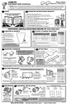
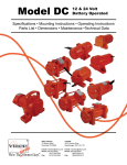
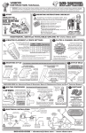
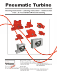
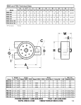
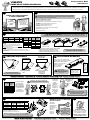
vibco
Pneumatic Ball
Vibrators
instruction manual
WARNING: Failure to read and follow these installation instructions and safety precautions could result in personal injury, equipment damage,
shortened service life or unsatisfactory equipment performance. All information in this document is vital to the proper installation and operation of
the equipment. It is important that all personnel who will be coming in contact with this product thoroughly read and understand this manual.
start
1
mounting instructions checklist
2
THANK YOU FOR CHOOSING
A VIBCO VIBRATOR!
The warranty is void if vibrator is not properly installed. During installation
follow and check off the following steps and your vibrator should provide
you with years of trouble-free service.
̸̸FILL OUT WARRANTY CARD!!!!
MENT OR
REPLACE
S
VER UNIT
CROSS O
G
IN
OUNT
CHECK M ORE
EF
B
A
E
AR
G UNIT.
IN
C
A
L
P
E
R
NEW
INSTALLAT
ION
START
HERE!
ty
an
rr
wa
̸̸Determine length of channel iron.
̸̸Select thickness of mounting plate & method of mounting.
̸̸STITCH weld mounting plate to channel iron.
̸̸Determine vibrator placement on bin.
̸̸STITCH weld channel iron to bin.
̸̸Place vibrator on mounting plate. Secure firmly.
̸̸Install safety chain or wire.
̸̸Connect pneumatics.
plates & channel selection
3
VIBRATOR
MNTNG PLATE
FORCE in LBS
THICKNESS
CHANNEL IRON FACTOR
SIZE
A
101 - 500
1/4" - 3/8"
3" x 4.1 lbs
3" x 5 lbs
2
501- 1200
1/2"
4" x 5.4 lbs
4" x 7.5 lbs
3
BIN WALL FACTOR
THICKNESS
B
1/8" (10 ga.)
or less
6
1/8" - 1/4"
5
1/4" - 3/8"
4
3/8" - 1/2"
3
NOTE:
YOU MUST STITCH WELD MOUNTING PLATE & CHANNEL IRON! NEVER
CONTINUOUSLY WELD. STOP WELDS 1” FROM ENDS TO STOP FATIGUE CRACKING.
FACTOR
A+B
USE
CH. IRON
LENGTH
9
5 - 7 FT.
(70 -80%)
8
4 - 6 FT.
(60 - 70%)
7
3 - 5 FT.
(50 - 60%)
6
2 - 4 FT.
(50 - 60%)
5
1 - 2 FT.
(50 - 60%)
4
N/A
1. Longer channel iron will not affect vibrator
1/2" & up
2
performance, but total channel length should not
exceed length of bin wall.
2. Percentages shown indicate % of bin wall height your channel iron
should be for shorter bins.
3. To match your vibrator on chart above, model number suffixes
generally correspond to pounds of force generated. For any questions,
consult VIBCO.
for bin plate
less than 3/16”
for bin plate
greater than 3/16”
THESE PLATES & CHANNEL LENGTHS ARE FOR MOST
COMMON APPLICATIONS. ADDITIONAL INFO FOR
OTHER APPLICATIONS AVAILABLE IN FULL DETAIL
VERSION OF INSTRUCTIONS ONLINE AT www.vibco.com
Drill/tap holes or use
studded plate
NEVER PLACE VIBRATOR DIRECTLY
ON SKIN OF BIN OR HOPPER!
800-633-0032 for Mounting Plates & Brackets, Spare & Replacement Parts and 24/7 Technical Support
Vibrator Placement
5
2 Vibrators On
A Single Bin
L
/3
L
L
1/
stitch weld mounting
Be sure you have selected the
proper length of channel using the
tables above (SECTION 4).
Improper mounting can
result in failure of
unit or damage
to equipment.
STITCH
WELDS
SHOULD
BE 3”
LONG
LEAVING
3” (7.5cm)
BETWEEN
EACH
WELD
2L
Conical
Bin
1/
1/
4t
3L
o1
L
1/
4t
o1
/3
L
4
NOT SURE HOW TO MOUNT?
CALL VIBCO TECH HELP 401-539-2392
1/2
Rectangular
Bin
THESE ARE JUST EXAMPLES
GO ONLINE TO
www.vibco.com
TO SEE MORE
DO NOT MOUNT
VIBRATOR DIRECTLY TO
SURFACE OF THE BIN !!!
Always use mounting plate &
channel iron
STITCH WELDS SHOULD
START & STOP 1” (2.5cm)
FROM BOTH ENDS OF
CHANNEL TO STOP
FATIGUE CRACKING
ADDITIONAL DETAILS AVAILABLE ONLINE AT www.vibco.com
6
bolting procedure
MAX
GRADE 5
TORQUE
BOLT SIZE
ft-lbs
1/4"
9
5/16"
18
3/8"
32
1/2"
78
5/8"
160
3/4"
260
For other bolt grades,
please consult VIBCO.
7
DAMAGE TO THE BIN OR THE VIBRATOR
WILL OCCUR IF NOT MOUNTED SECURELY!
All torque specs
are listed as a
WET TORQUE
recommendation.
Loctite 243 Blue
or equal should
be used to
ensure bolts do
not come loose.
Pneumatic hook up
TO DETERMINE CORRECT AIR HOSE SIZE**
BALL MODEL
NUMBER
MIN AIR
HOSE DIA
MIN FRL*
THREAD DIA
CFM
100-130
1/8”
1/4”
4-6
160-250
1/4”
1/4”
7 - 10
320-380
3/8”
3/8”
10 - 20
*F=filter R=regulator L=lubricator
**these for installation of single unit;
for multiple units adjust to maintain CFM
NOTE: On BB, BV and V models, the smaller INNER port is the air inlet and the larger port is the exhaust
Make sure
the vibrator
is secured
tightly.
Retighten
after the
first 10 -15
minutes of
operation &
check them
periodically
to maintain
proper
tightness.
June
Remember,
Check those
bolts!
August
NOTE:
If replacement installation,
you MUST check the weld on
the existing mount first!
NOTE for Clean or Sanitary
Environments:
BB & BV
models are
equipped with
a threaded
exhaust port to
allow for
exhaust
air to be
piped off
remotely.
July
FOR
LENGTHS UNDER
10 FT.
HOSE DIA. SHOULD
MATCH PORT SIZE.
OVER 10 FT.
CONSULT VIBCO.
8
restraint
ALWAYS
INSTALL
SAFETY CHAIN
Mount one end to the vibrator
and the other to the hopper
or bin above the vibrator
NEVER ATTACH CHAIN TO
THE MOUNTING PLATE
800-633-0032 • [email protected] • www.vibco.com
REV196-13
vibco
Pneumatic Ball
Vibrators
instruction manual
WARNING: Failure to read and follow these installation instructions and safety precautions could result in personal injury, equipment damage,
shortened service life or unsatisfactory equipment performance. All information in this document is vital to the proper installation and operation of
the equipment. It is important that all personnel who will be coming in contact with this product thoroughly read and understand this manual.
9
Pneumatic installation
LUBRICATION IS MANDATORY!
5’ solenoid to vibrator
To
Vibrator
To Gate
Operating Specs
Maximum Air Pressure
Air
Filter
Flow
Valve
Not Recommended
Air
Lubricator
Timer
Use SAE-10 or lighter oil
1 drop for every 10 cubic
ft/min (CFM) (available at any
industrial or auto supply store)
15’ lubricator to vibrator
11
10
Safe Operation
Air
Regulator
Solenoid
Valve
To Control
Switch
For best performance
DO NOT RUN vibrators
in series off one hose
Troubleshooting
Operating pressure should
not exceed 60 psi for BB100, BB-130, BB-160, BB190, BV-60, BV-130, V-100
and V-130.
Safe Operation
Not Recommended
My Material STILL Isn’t Moving!
1. Did you put your vibrator in the right location? Did you mount your vibrator properly?
2. Do you have the right vibrator for the job? Does it provide enough force? Is it the right frequency? Still not sure? Call VIBCO
Technical Support at 800-633-0032.
3. Do you run the vibrator when the process is stopped? Over running the vibrator can pack material in the bin or hopper. Send
us some digital photos to - [email protected] - we can help!
The Vibrator Won’t Start!
1. Check for dirt, Teflon tape, pipe dope, etc. in the airline, inlet opening or exhaust muffler.
2. Check air line for leakage. Quick disconnect air fittings can leak as well as restrict air flow.
3. Double check the size of your air line - is it large enough to give you the correct cubic feet per minute (CFM) and correct air
pressure (minimum required = 20 PSI)? See panel 7
4. Double check to see the air line is attached to the correct port (see #9).
Operating pressure
should not exceed 80 psi
for V-190, V-250, V-320,
V-380, BV-190, BV-250,
BV-320 and BV-380 units.
Warranty
All warranty claims must be submitted to VIBCO for approval prior to any repairs being done. Failure to do
so will void any and all warranty coverage. All repairs will be done at the VIBCO factory.
Errors, Shortages & Complaints
Complaints concerning goods received or errors should be made at once. Claims must be made within
five days after receipt of goods. Clerical errors are subject to correction. Damage during shipping must be
reported to the carrier, not VIBCO.
Returning Parts **
Parts should not be returned to VIBCO without prior authorization. Call VIBCO’s customer service department at 800-633-0032 (800-465-9709 in Canada) for a Return Goods Authorization (RGA) number. A
return authorization will be emailed or faxed to you. Use this as your packing slip. Return shipping must be
prepaid. Material returned may be subject to a 10% restocking fee. All returned shipments should clearly
display your name, address and original invoice number to ensure proper credit.
** Orders for custom equipment built to customer’s specifications are not returnable.
Maximum Temperature
350° F
175° C
The operating
temperature
of the vibrator
should not
exceed 350oF
(175oC).
Alternative HIGH TEMP
units are available. Consult
the factory with your
application information for
best recommendations.
800-633-0032 for Mounting Plates & Brackets, Spare & Replacement Parts and 24/7 Technical Support
Product Changes
VIBCO reserves the right to make changes in pattern, design or materials when deemed necessary, without prior notice or obligation to make corresponding changes in
previous models. To be sure of exact mounting dimensions, it is recommended that you obtain a certified dimensional drawing from the factory.
Ordering Spare Parts
Parts can be ordered through authorized distributors or from VIBCO’s Spare Parts Department. The following data should be provided when placing your spare parts
order:
From label:
Model number of unit.
From spare parts list: Reference number, part number, description & quantity required.
Shipping instructions: Specify shipping point and method of shipping.
For custom mounting applications or any other
questions:
800-633-0032
or
[email protected]
800-633-0032 • [email protected] • www.vibco.com
REV196-13