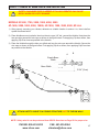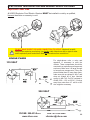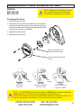
1
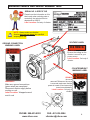
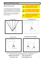
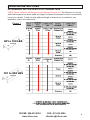
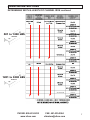
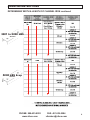
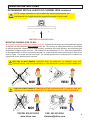
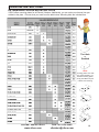
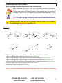
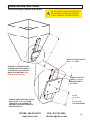
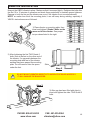
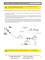
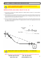
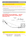
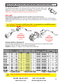
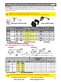
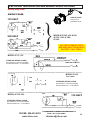
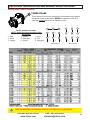
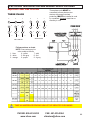
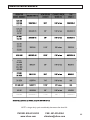
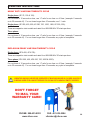
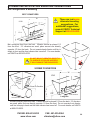
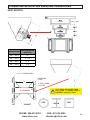
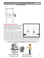
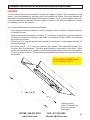
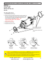
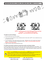
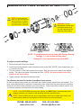
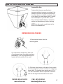
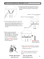
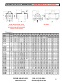
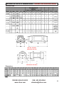
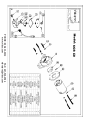
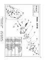
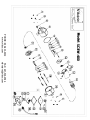
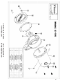
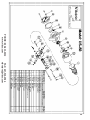
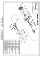
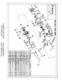
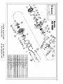
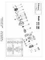
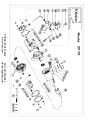
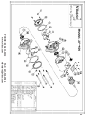
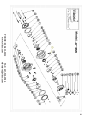
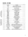
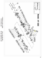
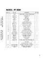
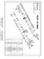
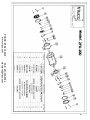
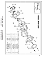
Electric Vibrators SCR l US l SFC l FC l HEAVY DUTY l EXPLOSION PROOF Mounting & Installation Instructions • Electrical Wiring Instructions Operating Instructions • Troubleshooting •Technical Data • Parts List Corporate HQ & Factory: 75 Stilson Road Wyoming, RI 02898 Phone: 800 633-0032 (401) 539-2392 Fax: (401) 539-2584 E-mail: [email protected] Website: www.vibco.com Western US: Phoenix, AZ 85254 Phone: 800 633-0032 (480) 596-1809 Fax: (480) 596-1614 Canada: 2215 Dunwin Drive Mississauga, ONT L5L 1X1 Phone: 800 465-9709 (905) 828-4191 Fax: (905) 828-5015 Southeastern US: Charlotte, NC 28277 Phone: 800 633-0032 (401) 539-2392 Fax: (401) 539-2584 Thank you for choosing VIBCO Vibrators for your vibration needs. You are now the owner of the finest electric vibrator available today, backed by complete manufacturer confidence in its quality and dependability. For reference, please complete the information below about your new VIBCO vibrator. Model Number: ____________________ Serial Number: ____________________ Date of Purchase: ____________________ WARNING: Failure to read and follow these installation instructions and safety precautions could result in personal injury, equipment damage, shortened service life or unsatisfactory equipment performance. All information in this document is vital to the proper installation and operation of the equipment. It is important that all personnel who will be coming in contact with this product thoroughly read and understand this manual. TABLE OF CONTENTS Warning Labels and Serial Number Tags .................................................................................xx Safety Instructions & Model Definitions ....................................................................................xx Mounting Instructions Checklist . ..............................................................................................xx Mounting Instructions.............................................................................................................. xxx Vibrator Installation.................................................................................................................. xxx Electrical Installation................................................................................................................ xxx Alternative Mounting Suggestions .......................................................................................... xxx Changing Output Force .......................................................................................................... xxx How to Fix a Crack in Your Bin................................................................................................ xxx Troubleshooting....................................................................................................................... xxx Technical Data and Dimensions................................................................................................xx Parts Lists & Breakdowns SCR LINE: MODEL 50, 60, 100, 200, 300, 400, (SCRW-400), 500, 1000 . ..................................xx US LINE: MODEL 100, 450, 700, 900, 1600..............................................................................xx SFC/FC LINE: MODEL SFC-100, 300; FC-100, 400..................................................................xx HEAVY DUTY LINE: MODEL 2P-75, 100, 150, 200, 450, 800, 1700, 2500, 3500, 4500, 5500. .... xx MODEL 4P-350, 600, 700, 1000, 1400, 2000, 3000, 5000, 10000.................................................xx MODEL 6P-500, 1000, 1500, 2500, 5000 ...................................................................................xx MODEL 8P-500, 750, 1250, 2500 ..............................................................................................xx EXPLOSION PROOF LINE: MODEL 2PX-200, 450; 4PX-350, 700, 2000, 5000........................xx Warranty & General Information . .............................................................................................xx PHONE: 800-633-0032 www.vibco.com FAX: 401-539-2584 [email protected] WARNING LABELS AND SERIAL NUMBER TAGS SERIAL NO. & SPECS TAG Please have the information on this label ready when ordering parts or contacting the technical service department at VIBCO. Label Location: On body of vibrator. Note: Always make sure that the vibrator does not run above the specified amperage for which the vibrator is wired. VOLTAGE LABEL GROUND CONNECTION WARNING LABEL 115 VOLTS WARNING! Be sure the voltage on the vibrator is correct for your power source. Label Location: On body of vibrator. COUNTERWEIGHT WARNING LABEL WARNING! Make sure ground connections (green wires) are completed. Disconnect electric supply before working on unit. Label Location: Wrapped around end of cord PHONE: 800-633-0032 www.vibco.com WARNING! Do not operate with the cover removed. Whenever the cover is removed make sure that the power is turned off and cannot be turned on accidentally. Label Location: On body of vibrator. FAX: 401-539-2584 [email protected] SAFETY INSTRUCTIONS WARNING: Failure to read and follow these installation instructions and safety precautions could result in personal injury, equipment damage, shortened service life or unsatisfactory equipment performance. All information in this document is vital to the proper installation and operation of the equipment. It is important that all personnel who will be coming in contact with this product thoroughly read and understand this manual. MODEL DEFINITIONS All VIBCO electric models offer the latest in vibration technology. They are also designed for long life to provide the maximum usage in any application. NOTE: Units are not watertight, only water resistant. Therefore applications exposed to harsh weather conditions must be covered by a dog house or some kind of protective covering. SCR LINE Adjustable speed and force. Can be adjusted while the vibrator is running. Easily adjusted eccentrics give additional force flexibility. No special wiring is needed. Totally enclosed for use in dusty or wet applications, inside or out. TENV (Totally Enclosed Non-Ventilated) Classified. US LINE Plug in high speed power. Low amperage draw with single phase motors. Speed adjustable through rheostat or electronic speed controls. Totally enclosed and lightweight for use in field applications. Rated for intermittent duty cycle only. TENV (Totally Enclosed Non-Ventilated) Classified. SFC/FC LINE Built for high ambient heat applications or where heat is transferred through the bin skin. Outside fan cooled. Rated for continuous duty and can take any number of starts and stops. Ease of mounting and low amperage draw make these units popular for OEM applications. Available in single or 3 phase. 50/60 Hz available. SFC Models are TENV (Totally Enclosed Non-Ventilated) Classified. FC Models are TEFC (Totally Enclosed Fan Cooled) Classified. HEAVY DUTY LINE Noiseless operation with maximum force and durability. Adjustable eccentrics. Available in single or 3 phase. Easily accessible terminal box for quick connection or voltage change. Oversized bearings and heavy duty electric motor for safety hight factor of watts per pound force. High heat resistant windings to take additional overload or heat. Totally enclosed and rated for continuous duty. TENV (Totally Enclosed Non-Ventilated) Classified. EXPLOSION PROOF LINE Rated for use in areas deemed hazardous by local authorities due to highly combustible materials -- i.e. with coal or grain dust, acetone fumes, etc. Built to UL specifications and UL approved. A variety of models available and rated for different classes and groups as indicated. Single and 3 phase available. Non-sparking components. Adjustable eccentrics. Class I and Class II models available. MUST BE INSTALLED BY A QUALIFIED LICENSED ELECTRICIAN TENV (Totally Enclosed Non-Ventilated) Classified. PHONE: 800-633-0032 www.vibco.com FAX: 401-539-2584 [email protected] MOUNTING INSTRUCTIONS CHECKLIST Factory warranty is void if vibrator is not installed per these instructions. DO NOT MOUNT VIBRATOR DIRECTLY TO SURFACE OF BIN OR HOPPER!!! IT WILL DAMAGE THE BIN/HOPPER. X oDetermine vibrator placement on bin. (See Vibrator Placement on Page #) oDetermine length of channel iron and position on side of bin. (Figure 1 on Page #) oDetermine style of mounting plate. (Figure 3 on Page #) oSelect method of STITCH welding mounting plate to channel iron. (Figure 4 on Page #). oSTITCH weld channel iron to bin. (See Welding Instructions on Page #) oAttach vibrator to mounting plate. Check the mounting plate for warping. Secure firmly. DO NOT OVER TIGHTEN THE BOLTS. (See Vibrator Installation on Page #) oInstall safety chain or cable. (See Safety Chain Installation on Page #) oConnect wiring for vibrator using the NEC Standards. (See Figure 5 on Page #) o Take a voltage reading at vibrator while running. VOLTS _______ o Take an amp reading while vibrator is running. AMPS _______ o Compare readings to standard values. Is the force the vibrator produces sufficient? Do you need more or less? See service instructions. oFILL OUT WARRANTY CARD AND MAIL TO VIBCO!!!! If the these steps are followed, your vibrator will be installed properly and should give you years of trouble free service. PHONE: 800-633-0032 www.vibco.com FAX: 401-539-2584 [email protected] MOUNTING INSTRUCTIONS Vibrator Placement For coarse materials the vibrator should be mounted approximately 1/3 of the distance from the discharge opening to the top of the sloped portion of the bin. For fine materials place the vibrator 1/4 of the distance from the discharge to the top of the sloped portion of the bin. Conical Bin Rectangular Bin PROPER PLACEMENT OF VIBRATOR IS ALWAYS LOCATED ON THE SLOPED PORTION OF THE BIN! DO NOT MOUNT VIBRATOR DIRECTLY TO SURFACE OF BIN OR HOPPER!!! IT WILL DAMAGE THE BIN/HOPPER. FOR EXPLOSION PROOF VIBRATORS MAKE SURE UL HAZARDOUS LOCATION MATCHES THE AREA’S CLASSIFICATION! 1/2 Rectangular Bin Two Vibrators On A Single Bin (Normally used to clean out bin or for larger bins) NOTE: These are the most common vibrator mounts. For additional options, please refer to Page # or consult VIBCO for further assistance. PHONE: 800-633-0032 www.vibco.com FAX: 401-539-2584 [email protected] MOUNTING INSTRUCTIONS DETERMINING WIDTH & LENGTH OF CHANNEL IRON VIBCO Electric Vibrators are designed to use standard channel iron. The thickness of your bin walls determines the minimum width and length of channel iron needed in order to successfully mount your vibrator. To find out what width and length of channel iron is needed for your application, refer to the chart below. Figure 1 UP to 100 LBS of force 101 to 500 LBS of force PHONE: 800-633-0032 www.vibco.com FAX: 401-539-2584 [email protected] MOUNTING INSTRUCTIONS DETERMINING WIDTH & LENGTH OF CHANNEL IRON continued 501 to 1200 LBS of force 1201 to 3000 LBS of force PHONE: 800-633-0032 www.vibco.com FAX: 401-539-2584 [email protected] MOUNTING INSTRUCTIONS DETERMINING WIDTH & LENGTH OF CHANNEL IRON continued 3001 to 5000 LBS of force 5000 LBS & up of force PHONE: 800-633-0032 www.vibco.com FAX: 401-539-2584 [email protected] MOUNTING INSTRUCTIONS DETERMINING WIDTH & LENGTH OF CHANNEL IRON continued Note: Longer channel iron will not affect the vibrator performance, but total channel iron length should not exceed the length of the bin wall. CENTERED ON CHANNEL IRON Mounting Channel Iron to Bin Never place the vibrator directly onto the skin of the bin. It should be mounted to a mounting plate and a piece of channel iron that has been stitch welded to the bin. This will help to stiffen the structure to be vibrated as well as spread the vibration over a larger surface, increasing the overall efficiency and diminishing the possibilities of fatigue cracks in the bin. The channel iron should extend 6 to 12 in. from the top and bottom of the sloped section of the bin and must be at least 6 in. longer than the vibrator mounting foot. Refer to the chart in Figure 1 for proper channel iron length. The vibrator should also be centered on the channel iron (see picture above) when properly mounted. FOR TWO (2) BOLT MODELS, VIBRATOR MUST BE PARALLEL TO CHANNEL IRON, NOT PERPENDICULAR, FOR PROPER SUPPORT OF THE VIBRATOR TO AVOID FLEXING & BURN OUT. NO! YES! FOR FOUR (4) BOLT MODELS, VIBRATOR MUST BE PERPENDICULAR TO CHANNEL IRON, NOT PARRALLEL, FOR PROPER SUPPORT OF THE VIBRATOR TO AVOID FLEXING & BURN OUT. NO! PHONE: 800-633-0032 www.vibco.com YES! FAX: 401-539-2584 [email protected] MOUNTING INSTRUCTIONS Determining proper Mounting Plate VIBCO offers mounting plates for all Electric Vibrators. Additionally, you can order your channel iron prewelded to the plate. Choose what you need from the table below. Mounting bolts are included free. Thru Hole or Studded NOTE: Mounting plates come with thru-holes standard. For studded mounting plates, simply add -ST to the part number when ordering. PHONE: 800-633-0032 www.vibco.com FAX: 401-539-2584 [email protected] 10 MOUNTING INSTRUCTIONS Stitch Welding the Mounting Plate to the Channel Iron Always start and stop welds 1 inch from ends to prevent heat concentration. In accordance with the appropriate picture below, weld 2 to 3 inches, skip 1 to 2 inches and repeat until securely welded. Use a straight edge to determine if mounting plate is still flat or if it warped at all during the welding process. If it did warp, be sure to shim vibrator feet as part of mounting process (see Page ##) NOTE: length & spacing of welds described here is different than that for mounting the channel iron to the bin. When welding to the legs of the channel iron, be sure to stitch weld to channel iron UNDERNEATH plate also! Figure 4 1a 1b 4 2b 2a 3b 3a 5 6 Different Suggestions for Combinations of Mounting Plate & Channel Iron 1a & b) Mounting plate welded to legs of channel iron (models used). 2a & b) Mounting plate on face of channel iron & holes drilled or tapped thru (models used) 3a & b) Mounting plate welded to two angle iron stiffeners instead of channel iron (models used). 4) Channel iron with holes drilled thru & nuts welded on back, or just holes drilled thru (models used) 5) Notch the channel for access to mounting bolts (models used) 6) Weld studs to back of channel (models used). NOTE: for a list of alternate mounting brackets, see pages 35 & 36 of the VIBCO General Catalog. PHONE: 800-633-0032 www.vibco.com FAX: 401-539-2584 [email protected] 11 MOUNTING INSTRUCTIONS Stitch Welding Channel Iron to Bin DO NOT MOUNT VIBRATOR DIRECTLY TO SURFACE OF BIN OR HOPPER!!! IT WILL DAMAGE THE BIN/HOPPER WELD STITCHES SHOULD BE 3” - 6” LONG BE SURE YOU HAVE ENOUGH CHANNEL ON EITHER SIDE OF THE VIBRATOR TO PROPERLY MOVE YOUR MATERIAL (SEE FIGURE ## ON PAGE ##) ALWAYS LEAVE AT LEAST 3” (7.5 cm) BETWEEN WELD STITCHES EITHER 1/4 L (for fine materials) or 1/3 L (for coarse materials) FROM THE DISCHARGE ALWAYS START AND STOP STITCHES AT LEAST 1” (2.5 cm) FROM THE END OF THE CHANNEL TO PREVENT CRACKING FROM HEAT CONCENTRATION PHONE: 800-633-0032 www.vibco.com FAX: 401-539-2584 [email protected] 12 VIBRATOR INSTALLATION Now put the VIBCO vibrator in place. Make sure that it is secured tightly. Retighten the bolts after the first 10 to 15 minutes of operation and check them periodically to maintain proper tightness. Damage to both the bin and the vibrator can occur if the vibrator is not mounted securely. NOTE: no matter how thick the mounting plate, it can still warp during welding, especially if VIBCO’s instructions are not followed. 1 1) Place vibrator on mounting plate, then insert and tighten 2 Grade 5 bolts on the 2 same end of the vibrator. See proper torque values listed to the right. Step 1 2) After tightening the first TWO Grade 5 bolts, look at the feet on the other end of the vibrator. If a gap exists between the mounting plate and feet of the vibrator, welding may have warped the mounting plate. You will need to shim the space under the feet. Shim Step 2 DO NOT MOUNT VIBRATOR DIRECTLY TO SURFACE OF BIN OR HOPPER !!! IT WILL DAMAGE THE BIN/HOPPER. Step 3 3 PHONE: 800-633-0032 www.vibco.com 4 3) After gap has been filled with shim(s), insert and tighten the other TWO Grade 5 bolts. FAX: 401-539-2584 [email protected] 13 SAFETY CHAIN or WIRE ROPE INSTALLATION SAFETY CHAIN/WIRE ROPE IS NEEDED IF FALLING VIBRATOR CAN CAUSE BODILY HARM OR COSTLY DAMAGE MODELS SCR-100; US-100; SFC/FC-all models; 2PX-200, 450; 4PX-350, 700 1) After properly mounting your vibrator, determine a suitable location to anchor it to, then install an eyebolt as shown below. 2) Place thimbles around eyebolts, then loop the wire rope (1/8” dia.) around the thimble. Next place the two rope clips around the wire rope as shown in the figure below. First applying Clip A as shown, then applying Clip B as close as possible to the thimble. 3) If hole for safety cable does not already exist, use a 3/8” drill to make a hole in the housing as shown below. Next place the thimble through the hole you drilled and loop the wire rope around the thimble. Secure the wire rope as shown in the figure below. First applying Clip A as shown, then applying Clip B as close as possible to the thimble. A Step 1 B Equals Base Width Base Width Step 2 Thimble Assembly 3-3/4” (9 cm) Leave 4-6” (10-15 cm ) slack in the rope A&B Foot of Vibrator Step 3 Drill a 3/8” (10mm ) Hole ATTACH SAFETY CABLE TO A STABLE STRUCTURE, NOT TO THE BIN WALL! NOTE: Safety wire kit can be purchased from VIBCO. See chart on Page XX for proper size. PHONE: 800-633-0032 www.vibco.com FAX: 401-539-2584 [email protected] 14 SAFETY CHAIN or WIRE ROPE INSTALLATION SAFETY CHAIN/WIRE ROPE IS NEEDED IF FALLING VIBRATOR CAN CAUSE BODILY HARM OR COSTLY DAMAGE MODELS SCR-300, 400; US-900, 1600; 2P-75, 100, 150 1) After properly mounting your vibrator, determine a suitable location to anchor it to, then install an eyebolt as shown below. 2) Place thimbles around eyebolts, then loop the wire rope (1/8” dia.) around the thimble. Next place the two rope clips around the wire rope as shown in the figure below. First applying Clip A as shown, then applying Clip B as close as possible to the thimble. 3) Place the thimble through the hole you drilled and loop the wire rope around the thimble. Secure the wire rope as shown in the figure below. First applying Clip A as shown, then applying Clip B as close as possible to the thimble. A B Equals Base Width Base Width 3-3/4” (9 cm) ATTACH SAFETY CABLE TO A STABLE STRUCTURE, NOT TO THE BIN WALL! NOTE: Safety wire kit can be purchased from VIBCO. See chart on Page XX for proper size. PHONE: 800-633-0032 www.vibco.com FAX: 401-539-2584 [email protected] 15 SAFETY CHAIN or WIRE ROPE INSTALLATION SAFETY CHAIN/WIRE ROPE IS NEEDED IF FALLING VIBRATOR CAN CAUSE BODILY HARM OR COSTLY DAMAGE MODELS SCR-500, 1000; 2P-200, 450; 4P-700, 1000; 6P-300, 500 1) After properly mounting your vibrator, determine a suitable location to anchor it to, then install an eyebolt as shown below. 2) Place thimbles around eyebolts, then loop the wire rope (1/8” dia.) around the thimble. Next place the two rope clips around the wire rope as shown in the figure below. First applying Clip A as shown, then applying Clip B as close as possible to the thimble. 3) Place the thimble through the hole you drilled and loop the wire rope around the thimble. Secure the wire rope as shown in the figure below. First applying Clip A as shown, then applying Clip B as close as possible to the thimble. THIS GROUP STILL IN PROCESS . . . NO EYE BOLT OR HOLE OR PLACE TO DRILL HOLE AVAILABLE YET B A Equals Base Width Base Width 3-3/4” (9 cm) ATTACH SAFETY CABLE TO A STABLE STRUCTURE, NOT TO THE BIN WALL! NOTE: Safety wire kit can be purchased from VIBCO. See chart on Page XX for proper size. PHONE: 800-633-0032 www.vibco.com FAX: 401-539-2584 [email protected] 16 SAFETY CHAIN or WIRE ROPE INSTALLATION SAFETY CHAIN/WIRE ROPE IS NEEDED IF FALLING VIBRATOR CAN CAUSE BODILY HARM OR COSTLY DAMAGE MODELS 2P-800, 1700, 2500, 3500, 4500, 5500 4P-1400, 2000, 3000, 5000, 10000; 6P-1000, 1500, 2500, 5000; 8P-ALL 1) After properly mounting your vibrator, determine a suitable location to anchor it to, then install an eyebolt as shown below. 2) Place thimbles around eyebolts, then loop the wire rope (1/8” dia.) around the thimble. Next place the two rope clips around the wire rope as shown in the figure below. First applying Clip A as shown, then applying Clip B as close as possible to the thimble. 3) Place the thimble through the hole you drilled and loop the wire rope around the thimble. Secure the wire rope as shown in the figure below. First applying Clip A as shown, then applying Clip B as close as possible to the thimble. A B Equals Base Width Base Width 3-3/4” (9 cm) ATTACH SAFETY CABLE TO A STABLE STRUCTURE, NOT TO THE BIN WALL! NOTE: Safety wire kit can be purchased from VIBCO. See chart on Page XX for proper size. PHONE: 800-633-0032 www.vibco.com FAX: 401-539-2584 [email protected] 17 ELECTRICAL INSTALLATION AND WIRING SPECIFICATIONS Maximum Amperage The operating amperage of the vibrator should not exceed the value listed in the tables below. If the vibrator runs above this amperage, it is most likely due to faulty installation. Check your mounting welds, and re-tighten bolts if necessary. Please refer to TROUBLESHOOTING on Page XX for additional details. SCR Line All SCR Models come equipped with a DC variable speed control and are single phase and 50/60 Hz. 115V units can simply be plugged into a grounded circuit. 230V units are shipped with speed control box but not a plug. You must hard wire the unit or connect your own plug per your circuitry. WARNING: The motor in all SCR units is DC. It is designed to be used WITH the speed control box. DO NOT connect directly to AC power! 90VDC 115VAC POWER CONVERTED AT SPEED CONTROL BOX FROM 115VAC INPUT TO 90VDC OUTPUT SETTING SPEED & FREQUENCY 90VDC POWER CONVERTED AT SPEED CONTROL BOX FROM 115VAC INPUT TO 90VDC OUTPUT 115VAC All SCR models are adjustable from 0 - 4000 VPM using speed control box supplied with vibrator. Numbers on dial are the approx. percentage of full frequency. EXAMPLE: setting of 70 = approx. 70% of 4000 VPM or 2800 VPM. TAKE AN AMPERAGE READING WHILE THE VIBRATOR IS RUNNING PHONE: 800-633-0032 www.vibco.com FAX: 401-539-2584 [email protected] 18 ELECTRICAL INSTALLATION AND WIRING SPECIFICATIONS US Line All US Models are single phase and 50/60 Hz. 115V units can simply be plugged into a grounded circuit. NOTE: 230V units are shipped without a plug. You must hardwire the unit or connect your own plug per your circuitry. US MODELS ARE RATED FOR INTERMITTENT DUTY ONLY Use 50% duty cycle where maximum run time = 30 minutes in any one hour period. WITH SWITCH BOX WITHOUT SWITCH BOX sfc - end mount & fc - fan cooled Line 115 VOLT 230 VOLT TAKE AN AMPERAGE READING WHILE THE VIBRATOR IS RUNNING PHONE: 800-633-0032 www.vibco.com FAX: 401-539-2584 [email protected] 19 ELECTRICAL INSTALLATION AND WIRING SPECIFICATIONS Heavy Duty Line SINGLE PHASE SINGLE PHASE Plug it in to a grounded circuit. 115 VOLT } 230 VOLT MODELS 2P-200, 450 & 800; 4P-700, 1000 & 1400; 6P-500 ALL REPLACEMENT PARTS ARE AVAILABLE FROM VIBCO FACTORY. CALL TODAY! MODEL 2P-75, 100 STANDARD WIRING SHOWN Any questions, consult a qualified, licensed electrician or call VIBCO. MODEL 2P-150 3 or 9 wire STANDARD WIRING SHOWN Any questions, consult a qualified, licensed electrician or call VIBCO. MODEL 4P-350, 600 115 VOLT STANDARD WIRING SHOWN Any questions, consult a qualified, licensed electrician or call VIBCO. PHONE: 800-633-0032 www.vibco.com FAX: 401-539-2584 [email protected] 20 ELECTRICAL INSTALLATION AND WIRING SPECIFICATIONS Heavy Duty Line continued THREE PHASE Three phase units must be connected to three phase motor starters with proper overload protection. MUST be installed to code by a qualified, licensed electrician or warranty is void. 6 Follow numbers on leads. NOTE: Some wires may be color-coded as follows: 1 - blue 4 - yellow 7 - pink 2 - white 5 - dark gray 8 - red 3 - orange 6 - purple 9 - light gray 5 4 6 5 4 9 8 7 9 8 7 3 2 1 3 2 1 L3 L2 L1 L3 L2 L1 230 or 240 volt 460 or 480 volt TAKE AN AMPERAGE READING WHILE THE VIBRATOR IS RUNNING PHONE: 800-633-0032 www.vibco.com FAX: 401-539-2584 [email protected] 21 ELECTRICAL INSTALLATION AND WIRING SPECIFICATIONS Explosion Proof Line All VIBCO Explosion Proof Electric Vibrators MUST be installed to code by a qualified, licensed electrician or warranty is void. DO NOT MAKE DIRECT OR HARD CONNECTION TO NIPPLE. Nipple will crack & compromise explosion proof rating. Use flexible cable. Attach one end to nipple & other end to explosion proof conduit box. Make all connections from conduit box. SINGLE PHASE For single-phase units, a relay and capacitor is necessary to start the vibrator. These components should be mounted in an explosion proof approved enclosure. Make sure it is large enough to house these components. If they are placed further than 10’ away from motor, make sure pick-up voltage is 140+7 and drop out voltage 40 or less. Nominal current in MA = 49. Coil DC resistant in OHMS 530 + 15% at 25OC. If further away from motor than 10’. a #14 or #12 wire might be necessary. 115 VOLT 230 VOLT PHONE: 800-633-0032 www.vibco.com FAX: 401-539-2584 [email protected] 22 ELECTRICAL INSTALLATION AND WIRING SPECIFICATIONS Explosion Proof Line continued Three phase units MUST be connected to three phase motor starters with proper overload protection. MUST be installed to code by a qualified, licensed electrician or warranty is void. THREE PHASE 6 5 4 6 5 4 9 8 7 9 8 7 3 2 1 3 2 1 L1 L3 L2 L1 L3 L2 230 or 240 volt 460 or 480 volt Follow numbers on leads. NOTE: Some wires may be color-coded as follows 1 - blue 4 - yellow 7 - pink 2 - white 5 - drk gray 8 - red 3 - orange 6 - purple 9 - lt gray TAKE AN AMPERAGE READING WHILE THE VIBRATOR IS RUNNING PHONE: 800-633-0032 www.vibco.com FAX: 401-539-2584 [email protected] 23 ELECTRICAL INSTALLATION AND WIRING SPECIFICATIONS overload protection section needed here Maximum Operating Temperature The skin temperature of the vibrator should not exceed 200oF (93oC). If skin temperature exceeds this, consult VIBCO for alternate solutions. 93oC 200o F VIBRATOR MAINTENANCE SCR LINE LUBRICATION Bearings are pre-lubricated for life. BRUSHES Unit has two brushes. Brush life is approximately 1,000 hours. To change brushes, remove brush caps and brushes. Make sure new brush slides freely in brush slot (if not, file down gently to fit). See chart on next page for correct replacement measurements and part numbers. US LINE LUBRICATION Bearings are pre-lubricated for life. BRUSHES Unit has two brushes. Brush life is approximately 1,000 hours. To change brushes, remove brush caps and brushes. Make sure new brush slides freely in brush slot (if not, file down gently).The brush life is dependent on the duty cycle.See chart on next page for correct replacement measurements and part numbers. DUTY CYCLE See page XXX for duty cycle details. PHONE: 800-633-0032 www.vibco.com FAX: 401-539-2584 [email protected] 24 VIBRATOR MAINTENANCE NOTE: a longer duty cycle considerably decreases the brush life. PHONE: 800-633-0032 www.vibco.com FAX: 401-539-2584 [email protected] 25 VIBRATOR MAINTENANCE SFC/FC LINE LUBRICATION Bearings are pre-lubricated for life. HEAVY DUTY LINE LUBRICATION The ball bearings in the 2P-75, 2P-200, 2P-450, 4P-350, 4P-700, 4P-1000, 6P-500, FC, SFC, SPR, US, and SCR, are pre-lubricated for life. Model 2P-800 has one pre-lubricated ball bearing and one roller bearing. All other models have two roller bearings. Roller bearings last much longer than ball bearings. However, the roller has a larger contact area than the ball and needs more lubricant. Therefore, they have to be re-lubricated at certain intervals. For vibrators with 3450 RPM, lubricate every two weeks for continuous duty or 400 or 500 operating hours; for 1725 RPM vibrators, every 1000 to 2000 operating hours or every month for continuous duty. Use 2.5 to 3 grams (two pumps with standard manual grease gun). Do not over grease, otherwise it will leak out. Removing the end cover to find out if unit has been overgreased. The same amount should be on inside of bearings as on the stator side. If there is too much, unit should be taken apart and cleaned. For vibrators without a grease nipple (2P-75, 100, 150, 200, 450, 800), the outside eccentric and bearing cover have to be removed. If the bearing has a grease seal, remove it and discard it, remove as much grease as possible and repack bearing. RECOMMENDED LUBRICANT EXPLOSION PROOF LINE LUBRICATION PHONE: 800-633-0032 www.vibco.com FAX: 401-539-2584 [email protected] 26 OPERATING INSTRUCTIONS To Obtain Maximum Performance It is not necessary to operate the vibrator continuously or at maximum output to obtain maximum performance. Timers, etc. should be used to tune the timing of the vibrator for optimum performance and ensure a longer life. SCR LINE RUN TIME/DUTY CYCLE All SCR Models are are rated for CONTINUOUS DUTY at frequency settings between 950 - 2500 vibrations per minute (VPM) - which is approx. 25 to 60 on speed control dial. For frequencies below 950 or above 2500 VPM, rating is INTERMITTENT DUTY. Use 50% duty cycle where maximum run time = 30 minutes in any one hour period. NOTE: Duty cycle can be increased by adding additional ventillation. Consult VIBCO for details. US HIGH FREQUENCY LINE RUN TIME/DUTY CYCLE All US Models are are rated for INTERMITTENT DUTY. Use 50% duty cycle where maximum run time = 30 minutes in any one hour period. NOTE: Duty cycle can be increased by adding additional ventillation. Consult VIBCO for details. sfc - end mount & fc - fan cooled LINE RUN TIME/DUTY CYCLE PHONE: 800-633-0032 www.vibco.com FAX: 401-539-2584 [email protected] 27 OPERATING INSTRUCTIONS HEAVY DUTY LINE RUN TIME/DUTY CYCLE Single phase (2P-75, 100 & 150): For run times of 10 seconds or less, use 1:7 ratio for run time vs. off time. (example: 5 seconds on to 35 seconds off). For run times longer than 10 seconds, use 1:1 ratio. Single phase (2P-200, 450, 800; 4P-350, 700, 1000, 1400; 6P-300, 500): These are capacitor start models and rated for a MAXIMUM of 30 starts per hour. Three phase: For run times of 10 seconds or less, use 1:7 ratio for run time vs. off time. (example: 5 seconds on to 35 seconds off). For run times longer than 10 seconds, any cycle is acceptable. EXPLOSION PROOF LINE RUN TIME/DUTY CYCLE Single phase (2PX-450; 4PX-700): These are capacitor start models and rated for a MAXIMUM of 30 starts per hour. Three phase (2PX-200, 450; 4PX-350, 700, 2000 & 5000): For run times of 10 seconds or less, use 1:7 ratio for run time vs. off time. (example: 5 seconds on to 35 seconds off). For run times longer than 10 seconds, any cycle is acceptable. vibrator should never be operated if bin discharge is closed, unless it is being used for a short period to clean out a nearly empty hopper. DON’T FORGET TO MAIL YOUR WARRANTY CARD! PHONE: 800-633-0032 www.vibco.com Y ANT R WAR FAX: 401-539-2584 [email protected] 28 ALTERNATIVE APPLICATION MOUNTING SUGGESTIONS Bin Configuration & Mounting Belt Conveyors These are just some alternate mounting suggestions. For additional suggestions, consult VIBCO Technical Support at 800-633-0032. W 1/3 W 1/3 L L Flow Direction Belt conveyors feed from the front. Vibrator should be placed 1/3 from the front. If 2 vibrators are used, place second one directly opposite 1/3 from the back. Do not operate back vibrator until bin is empty in front and the front vibrator has turned off. For more details, call VIBCO at 800-633-0032. DO NOT MOUNT VIBRATOR DIRECTLY TO SURFACE OF BIN OR HOPPER!!! IT WILL DAMAGE THE BIN/HOPPER. X Screw Conveyors W 1/3W Alterna te Side fo r Vibrato r As Close As Possible L Flow Direction 1/3L Flow Direction Long Bin Screw conveyors feed from back. Vibrator should be placed 1/3 from the back. If 2 vibrators are used, place 2nd one directly opposite 1/3 from the front. Do not operate front vibrator until bin is empty in back and the back vibrator has turned off. For more details, call VIBCO at 800-633-0032. PHONE: 800-633-0032 www.vibco.com FAX: 401-539-2584 [email protected] 29 ALTERNATIVE APPLICATION MOUNTING SUGGESTIONS HEAT MOUNTS TEMPERATURE PIPE/I-BEAM/TUBE LENGTH (L) 450oF - 500oF 12" o o o o o o 300 F - 450 F 8" - 10" 200 F - 300 F 6" - 8" 140 F - 200 F 4" - 6" 5” or 6” CHANNEL IRON L MOUNTING PLATE 4” PIPE, I-BEAM OR TUBE NOTE: Must be longer than insulation. If longer than 12” is needed, consult VIBCO. 12” MAXIMUM GUSSET PHONE: 800-633-0032 www.vibco.com PIPE I-BEAM TUBE FAX: 401-539-2584 [email protected] 30 ALTERNATIVE APPLICATION MOUNTING SUGGESTIONS LIVE BOTTOM BINS INTERFERENCE VIBRATION For really tough materials, large bins, bins containing different particle sizes or bins used to store different materials, lnterference Vibration will move the materials more efficiently. This uses TWO vibrators on the bin with different frequencies (speeds) - most commonly at 3600 and 1800 rpm. EXAMPLE: A bin containing 15,000 Ibs. of material L L needs 1500 Ibs. of vibration force. Use two vibrators, 1/2 L 1/4 TO 1/3 L 1800 rpm one at 1800 rpm with 700 Ibs. maximum force, and 3600 rpm one at 3600 rpm with 800 Ibs. maximum force. Mount the 3600 rpm unit closest to the discharge -- 1/3 up the bin side, and the 1800 rpm unit on the opposite side and 1/2 way up the bin side. The frequency of each vibrator will “interfere” with the other and create a simulated vibration ranging from 3600 + 1800 = 5400 vpm to 3600 - 1800 = 1800 vpm. The vibration will go through the material’s “resonance” frequency and flow easily. Consult VlBCO for further details. Is your bin or hopper made of a material not suitable for welding?? Call VIBCO now and ask about our VIBRAGrip suction cup mount system. PHONE: 800-633-0032 www.vibco.com FAX: 401-539-2584 [email protected] 31 ALTERNATIVE APPLICATION MOUNTING SUGGESTIONS Chutes In order to successfully move material in a chute, the “angle of repose” of the material has to be known. It can be measured by pouring a cup of the material on a table. The angle between the table and the cone the material makes is the “angle of repose”. To move the material in the chute, it should be inclined no less than 1/2 of the “angle of repose” If this cannot be obtained, a feeder is necessary to move the material. For optimum performance follow these guidelines: • • • • Force (impact) needed on vibrator is equal to weight of chute + vibrator + maximum amount of material in chute. Chutes must have an inclination of at least 10o for vibrators to be able to move the material. If inclination is less, the chute has to be made into a feeder. Contact VIBCO for selecting the proper size vibrator. Chutes up to 6 ft. long can generally be handled by one vibrator mounted approximately 1/3 from the discharge. On chutes from 6 - 10 ft. long, two vibrators are needed. One should be placed 18 to 24 inches from the discharge. The other approximately in the middle of the chute. Since chutes are very sensitive to vibration, provision should be made to move the lower vibrator 6 inches in either direction. This could mean the difference between moving or not moving the material. FOR CHUTES LONGER THAN 10 FT. CONSULT VIBCO Place mounting plate 1/3 distance up the chute from the discharge. PHONE: 800-633-0032 www.vibco.com FAX: 401-539-2584 [email protected] 32 CHANGING OUTPUT FORCE / ECCENTRIC SETTINGS MODELS: SCR-100, 200 SFC-100, 300 NOTE: Models US-100, 450 and 700 have fixed eccentrics and are NOT adjustable. Consult factory for alternate force options. To change the force: 1. Remove the end cover. 2. Remove the cap screw that holds the outer eccentric to the inner eccentric and turn the outer eccentric so that the numbered hole aligns with the threaded hole in the inner eccentric (see below). 3. Replace the cap screw. 4. Replace the end cover. Remove cap screw and adjust as shown below. Then replace the bolt and cover. Maximum Force Intermittent Duty Only CAP SCREW Factory Setting Maximum Setting for Continuous Duty CAP SCREW CAP SCREW Minimum Force Optimum Setting for Long Life of Vibrator NOTE: If you INCREASE the force of the vibrator, you MUST take a new amperage draw reading to ensure your vibrator is still operating within the specified limits. NOTE: These models can only be run intermittently when set to higher than factory set output forces (maximum running time of 30 minutes in any one hour period). PHONE: 800-633-0032 www.vibco.com FAX: 401-539-2584 [email protected] 33 CHANGING OUTPUT FORCE / ECCENTRIC SETTINGS continued MODELS: SCR-300, 400 US-900, 1600 2P-75, 100, 150, 200 4P-350 To change the force: 1. Remove both end covers. 2. Remove the cap screw that holds the outer eccentric to the inner eccentric and turn the outer eccentric so that the numbered hole aligns with the threaded hole in the inner eccentric (see below). NOTE: You must set both ends of the vibrator to the same setting. 3. Replace the cap screw. 4. Replace both end covers. Remove cap screw and adjust as shown below. Then replace the bolt and cover. Maximum Force Intermittent Duty Only CAP SCREW Factory Setting Maximum Setting for Continuous Duty CAP SCREW CAP SCREW Minimum Force Optimum Setting for Long Life of Vibrator NOTE: If you INCREASE the force of the vibrator, you MUST take a new amperage draw reading to ensure your vibrator is still operating within the specified limits. NOTE: These models can only be run intermittently when set to higher than factory set output forces (maximum running time of 30 minutes in any one hour period). PHONE: 800-633-0032 www.vibco.com FAX: 401-539-2584 [email protected] 34 CHANGING OUTPUT FORCE / ECCENTRIC SETTINGS continued MODELS: 2P-450, 800, 1700, 2500 4P-600, 700, 1000, 1400, 2000, 3000, 5000, 10000 6P - ALL MODELS 8P- ALL MODELS .N IM E C RR A H TIW RO WO .XA M WOR RA H E TI I N 6 .RE 6 .P TE LEFT 5 4 RM I T T . OP . PO .TNOC 2 3 M .X A N I E L PU 3 # PO .TNO C 2 1 F 4 5 .O I NT E R MI T T .RE 1 . IM F N U E NI RO L C #P W RIGHT NOTE: These vibrators are set to Setting #3 (Factory Setting). Settings 1 - 3 are continuous duty rated. Settings 4 - 6 are intermittent duty rated ONLY. To adjust eccentric settings: 1. Remove both end covers from vibrator. 2. Loosen the bolt that holds the outer, labeled eccentric to the shaft. (NOTE: Some models have only (1) eccentric per side). 3. Turn the eccentric on the shaft to adjust force output. Align the arrow on the shaft to the desired setting. The higher the number, the greater the force. NOTE: You must set both ends of the vibrator to the same setting. 4. Tighten eccentric bolts and reinstall end covers. For vibrators mounted in tandum to produce linear motion on feeders & tables: In order to produce linear motion you must make sure vibrators rotate opposite from one another. The force output labels should be opposite to one another when viewed from the same side (one increases clockwise, the other counter-clockwise as in picture above). Follow instructions as above, and be sure you set both vibrators and both ends to the same setting. NOTE: If you INCREASE the force of the vibrator, you MUST take a new amperage draw reading to ensure your vibrator is still operating within the specified limits. NOTE: These models can only be run intermittently when set to higher than factory set output forces (maximum running time of 30 minutes in any one hour period). PHONE: 800-633-0032 www.vibco.com FAX: 401-539-2584 [email protected] 35 CHANGING OUTPUT FORCE / ECCENTRIC SETTINGS continued EXPLOSION PROOF MODELS: 2PX-200, 450 4PX-350, 700, 2000, 5000 NOTE: To avoid electrical shock, be sure to disconnect and tag out/lock out vibrator connection before adjusting any internal parts of vibrator. WARNING: Do not disassemble vibrator any more than shown here. You will compromise the Explosion Proof rating. LEFT RIGHT NOTE: These vibrators are set to Setting #3 (Factory Setting). Settings 1 - 3 are continuous duty rated. Settings 4 - 6 are intermittent duty rated ONLY. To adjust eccentric settings: 1. Remove both end covers from vibrator. 2. Loosen the bolt that holds the outer, labeled eccentric to the shaft. (NOTE: Some models have only (1) eccentric per side). 3. Turn the eccentric on the shaft to adjust force output. Align the arrow on the shaft to the desired setting. The higher the number, the greater the force. NOTE: You must set both ends of the vibrator to the same setting. 4. Tighten eccentric bolts and reinstall end covers. For vibrators mounted in tandum to produce linear motion: In order to produce linear motion you must make sure vibrators rotate opposite from one another. The force output labels should be opposite to one another when viewed from the same side (one increases clockwise, the other counter-clockwise as in picture above). Follow instructions as above, and be sure you set both vibrators and both ends to the same setting. NOTE: If you INCREASE the force of the vibrator, you MUST take a new amperage draw reading to ensure your vibrator is still operating within the specified limits. NOTE: These models can only be run intermittently when set to higher than factory set output forces (maximum running time of 30 minutes in any one hour period). PHONE: 800-633-0032 www.vibco.com FAX: 401-539-2584 [email protected] 36 HOW TO FIX A CRACK IN YOUR BIN Cracked Bin Skin Cracked bin skins are usually due to improper welding, improper mounting of the vibrator to the bin, too high an output force from the vibrator or vibrator running too long on an empty (or nearly empty) bin. If cracks have developed on your bin skin, follow the procedure detailed below to repair the cracks and eliminate any further cracking. Note: bin skin cracks usually start at the ends of the channel iron. REPAIRING BIN CRACKS 1) Remove the vibrator from the mounting plate. 2) Locate where cracks stop. Take note of any places where the cracks may have branched off. It is very important that you located all the branches of the crack. 3) Drill holes thru bin skin at the end of every crack (on every branch) to prevent cracks from continuing across skin. For average size cracks use a 1/8” to 1/4” drill. Remember that it is important is that the drill size be larger than the width of the crack. PHONE: 800-633-0032 www.vibco.com FAX: 401-539-2584 [email protected] 37 HOW TO FIX A CRACK IN YOUR BIN continued 4) Once holes are drilled, weld along all the cracks to the holes and then over the entire hole. Be sure to cover the entire crack and hole to prevent further damage. At least 4” ( 10cm ) past drill point At least 4” ( 10cm ) past drill point 5) Choose a length of angle iron to reinforce the area of the bin where cracking occurred. To determine on the appropriate length, make sure that the angle iron goes at least 4” ( 10 cm ) past the end of the outermost drill points / end of cracks. 6) After choosing an appropriate 1” length of angle iron, weld it in place. Starting 1” (2.5 cm) from the end of the angle iron, weld stitches 3-6” (7.5-15 cm ) long, leaving at least 3” (7.5 cm) between the stitches (see Page xx). Be sure to stop welds 1” ( 2.5 cm ) from the end of the angle iron. Angle Iron NOTE: Be sure to weld both top and bottom of angle iron 7) Now you can remount vibrator on mounting plate. (Refer to Page xx for proper Vibrator Installation Instructions) NOTE: Take an amperage reading the first time you start the vibrator after repairing cracks. PHONE: 800-633-0032 www.vibco.com FAX: 401-539-2584 [email protected] 38 HELP! MY VIBRATOR ISN’T WORKING! TROUBLE SHOOTING SECTION: Cracks have developed on bin wall The improper welding of a vibrator to bin stiffeners often results in fatigue cracks in the bin. This can be repaired to prevent further cracking by properly welding stiffeners to the bin side. To accomplish this see Welding Instructions on Pages xxx. How do I know if I welded everything correctly? To check if you welded everything correctly see if the mount affects the performance of the vibrator. VIBCO recommends you get a reading of the amperage draw of the vibrator before it is bolted to the channel iron on your bin. Place the vibrator on any soft material you might have (pillows, seat cushions, etc.) Turn the vibrator on and turn the control box dial to its maximum setting. Take an amperage reading and compare it to the values found on Page xx (or on the Serial # & Specs Tag on the unit). If the two values match, reinstall the vibrator according the instructions on Page 9 and take another amperage reading while the vibrator is running. If the amperage reading is now still too high then: 1) Check that your bolts have been tightened to the torque specified on Page xx. 2) Make sure the vibrator has been properly shimmed and stabilized. 3) If both of these conditions are satisfied, then reinspect your welds to see if there are any additional cracks. Repair them according to instructions on Pages xx. The vibrator should not be moving excessively when in operation. If you are able to read the Serial # & Specs Tag, then the amount of motion is acceptable. If you cannot, refer to the mounting instructions to fix the problem or consult VIBCO. PHONE: 800-633-0032 www.vibco.com FAX: 401-539-2584 [email protected] 39 HELP! MY VIBRATOR ISN’T WORKING! TROUBLE SHOOTING SECTION: SCR MODELS is your material not moving? 1. Did you put your vibrator in the right location? Did you mount your vibrator properly? 2. Do you have the right vibrator for the job? Does it provide enough force? Is it the right frequency? Is it set to the maximum force? See eccentric setting info to left. Still not sure? Call VIBCO Technical Support at 800-633-0032. vibrator won’t even start? 1. Check for blown fuses in the vibrator. 2. Check power supply to unit. Are you getting the proper voltage? NOTE: Remember that SCR units are built with a 90VDC motor powered by 115VAC power, converted at the speed control box. 3. Check field continuity, if “open” field winding is burned or has a short, replace field. If unsure how to check continuity, call VIBCO or consult a licensed electrician. 4. Check control potentiometer. If shorted, replace. 5. Check vibrator brushes for wear. Each unit has two brushes. Refer to full detail manual at www.vibco.com for correct brush lengths. Replace if worn below minimum length. did the vibrator stop running? 1. FUSES FUSES FUSES 2. Check power supply to unit. 3. Check vibrator brushes for wear. Each unit has two brushes. Refer to full detail manual at www.vibco.com for correct brush lengths. Replace if worn below minimum length. 4. Are you running the vibrator in a wet or washdown environment? Consult VIBCO about washdown rated models. 5. Are you running the vibrator in a high temperature environment? Consult VIBCO about high temp rated models. Refer to full detail instructions for proper mounting in high temp applications. 6. Are you running the vibrator continously? All VIBCO heavy duty models are rated for continuous duty but only at certain eccentric settings. See diagrams to left for proper output force settings for continuous duty. NOTE: For best performance and vibrator life cycle, it is best to run them intermittently. Consult VIBCO for available timers. 7. Are you repeatedly stopping and starting the vibrator? This can overload the vibrator. Use the following guidelines for proper timing of starts and stops: PHONE: 800-633-0032 www.vibco.com FAX: 401-539-2584 [email protected] 40 HELP! MY VIBRATOR ISN’T WORKING! TROUBLE SHOOTING SECTION: SCR MODELS continued RUN TIME/DUTY CYCLE All SCR Models are are rated for CONTINUOUS DUTY at frequency settings between 950 - 2500 vibrations per minute (VPM) - which is approx. 25 to 60 on speed control dial. For frequencies below 950 or above 2500 VPM, rating is INTERMITTENT DUTY. Use 50% duty cycle where maximum run time = 30 minutes in any one hour period. NOTE: Duty cycle can be increased by adding additional ventillation. Consult VIBCO for details. NOTE: Proper force for full hopper can be excessive for empty or nearly empty hopper. us high frequency MODELS vibrator won’t even start? 1. Check power supply to unit. Are you getting the proper voltage? Has the thermal overload protection tripped? 2. Check vibrator brushes for wear. Each unit has two brushes. Refer to full detail manual at www.vibco.com for correct brush lengths. Replace if worn below minimum length. 3. Check field & armature continuity. If either is burned or has a short, replace. If unsure how to check continuity, call VIBCO or consult a licensed electrician. did the vibrator stop running? 1. Check power supply to unit. 2. FOR Model US-900 & 1600 ONLY -- Has the thermal overload protection tripped? If overload protection has tripped, wait a minimum of two (2) minutes then reset by switching firmly off and then on again. 3. Is there an ununusual sound (banging) coming from the vibrator? This usually means that the vibrator is has loosened or the mounting is cracked. Check the vibrator mounting bolts for tightness. Check the mounting structure. New installations may be too weak. Reinforce mount area immediately by adding stiffeners like angle iron or channel iron. In existing installations look for cracks in mounting angle iron or plates. Also look for fatigued or cracked welds. Repair and reinforce immediately. PHONE: 800-633-0032 www.vibco.com FAX: 401-539-2584 [email protected] 41 HELP! MY VIBRATOR ISN’T WORKING! TROUBLE SHOOTING SECTION: us high frequency MODELS continued Check vibrator and bracket connection to the form or mold. If clamps are loose or wedge is not properly inserted, it may cause vibrator to run hot and cause internal damage. Brackets may need to be adjusted or replaced. 4. Check vibrator brushes for wear. Each unit has two brushes. Refer to full detail manual at www.vibco.com for correct brush lengths. Replace if worn below minimum length. 5. Are you running the vibrator continously? All VIBCO high frequency electric models are rated for intermittent duty only. NOTE: Consult VIBCO for available timers to help run vibrators at proper intervals. 6. Are you repeatedly stopping and starting the vibrator? This can overload the vibrator. Use the following guidelines for proper timing of starts and stops: RUN TIME/DUTY CYCLE All US Models are are rated for INTERMITTENT DUTY only. Use 50% duty cycle where maximum run time = 30 minutes in any one hour period. For run times of 10 seconds or less, use 1:7 ratio for run time vs. off time. (example: 5 seconds on to 35 seconds off). For run times longer than 10 seconds, any cycle is acceptable. NOTE: Duty cycle can be increased by adding additional ventillation. Consult VIBCO for details. sfc - end mount & fc - fan cooled MODELS is your material not moving? PHONE: 800-633-0032 www.vibco.com FAX: 401-539-2584 [email protected] 42 HELP! MY VIBRATOR ISN’T WORKING! TROUBLE SHOOTING SECTION: sfc - end mount & fc - fan cooled MODELS continued PHONE: 800-633-0032 www.vibco.com FAX: 401-539-2584 [email protected] 43 HELP! MY VIBRATOR ISN’T WORKING! TROUBLE SHOOTING SECTION: heavy duty MODELS is your material not moving? 1. Did you put your vibrator in the right location? Did you mount your vibrator properly? 2. Do you have the right vibrator for the job? Does it provide enough force? Do you have the vibrator set to the maximum force? (see left) Is it the right frequency? Still not sure? Call VIBCO Technical Support at 800-633-0032. vibrator won’t even start? 1. Check power supply to unit. Are you getting the proper voltage? Has the thermal overload protection tripped? 2. Check stator continuity, if “open” stator winding is burned or has a short, replace stator. If unsure how to check continuity, call VIBCO or consult a licensed electrician. did the vibrator stop running? 1. Check power supply to unit. 2. Has the thermal overload protection tripped? Single phase units are supplied with overload switches. Three phase units must be connected to three phase motor starters with proper overload protection. If overload protection has tripped, wait a minimum of two (2) minutes then reset by switching firmly off and then on again. 3. Are you running the vibrator in a wet or washdown environment? Consult VIBCO about washdown rated models. 4. Are you running the vibrator in a high temperature environment? Consult VIBCO about high temp rated models. Refer to full detail instructions for proper mounting in high temp applications. 5. Are you running the vibrator continously? All VIBCO heavy duty models are rated for continuous duty but only at certain eccentric settings. See diagrams to left for proper output force settings for continuous duty. NOTE: For best performance and vibrator life cycle, it is best to run them intermittently. Consult VIBCO for available timers. 6. Are you repeatedly stopping and starting the vibrator? This can overload the vibrator. Use the following guidelines for proper timing of starts and stops: PHONE: 800-633-0032 www.vibco.com FAX: 401-539-2584 [email protected] 44 HELP! MY VIBRATOR ISN’T WORKING! TROUBLE SHOOTING SECTION: HEAVY DUTY MODELS continued RUN TIME/DUTY CYCLE Single phase (2P-75, 100 & 150): For run times of 10 seconds or less, use 1:7 ratio for run time vs. off time. (example: 5 seconds on to 35 seconds off). For run times longer than 10 seconds, use 1:1 ratio. Single phase (2P-200, 450, 800; 4P-350, 700, 1000, 1400; 6P-300, 500): These are capacitor start models and rated for a MAXIMUM of 30 starts per hour. Three phase: For run times of 10 seconds or less, use 1:7 ratio for run time vs. off time. (example: 5 seconds on to 35 seconds off). For run times longer than 10 seconds, any cycle is acceptable. NOTE: Proper force for full hopper can be excessive for empty or near empty hopper. explosion proof MODELS continued is your material not moving? 1. Did you put your vibrator in the right location? Did you mount your vibrator properly? 2. Do you have the right vibrator for the job? Does it provide enough force? Do you have the vibrator set to the maximum force? (see left) Is it the right frequency? Still not sure? Call VIBCO Technical Support at 800-633-0032. vibrator won’t even start? 1. Check power supply to unit. Are you getting the proper voltage? Has the thermal overload protection tripped? See overload information below. 2. Check stator continuity, if “open” stator winding is burned or has a short, replace stator. If unsure how to check continuity, call VIBCO or consult a licensed electrician or refer to detailed instruction manual online at www.vibco.com. PHONE: 800-633-0032 www.vibco.com FAX: 401-539-2584 [email protected] 45 HELP! MY VIBRATOR ISN’T WORKING! TROUBLE SHOOTING SECTION: explosion proof MODELS continued did the vibrator stop running? 1. Check power supply to unit. 2. Has the thermal overload protection tripped? Single phase units are supplied with a capacitor and relay and must be connected to a single phase motor starter with proper individual overload protection in a properly UL-rated enclosure . Is your vibrator connected correctly? Three phase units must be connected to three phase motor starters with proper individual overload protection. Is your vibrator connected correctly? If overload protection has tripped, wait a minimum of two (2) minutes then reset. Refer to wiring chart on PAGE XXX for details. 3. Have you checked your bin/hopper for fatigue cracks? Repair any you find as per detailed instructions in the full detail manual found online at www.vibco.com. 4. Are you running your vibrator on an empty or nearly empty bin? Proper force for full hopper can be excessive for empty or nearly empty hopper. For hopper clean-out, use vibrator intermittently only to prevent overload or burn out. 5. Are you running the vibrator continously? All VIBCO heavy duty models are rated for continuous duty but only at certain eccentric settings. See diagrams to left for proper output force settings for continuous duty. NOTE: For best performance and vibrator life cycle, it is best to run them intermittently. VIBCO offers timers to help facilitate this. Consult factory for details. 6. Are you running the vibrator in a high temperature environment? Consult VIBCO about high temp rated models. Refer to full detail instructions for proper mounting in high temp applications. 7. Are you running the vibrator in a wet or washdown environment? Consult VIBCO about washdown rated models. 8. Are you repeatedly stopping and starting the vibrator? This can overload the vibrator. Use the following guidelines for proper timing of starts and stops: PHONE: 800-633-0032 www.vibco.com FAX: 401-539-2584 [email protected] 46 HELP! MY VIBRATOR ISN’T WORKING! TROUBLE SHOOTING SECTION: explosion proof MODELS continued RUN TIME/DUTY CYCLE Single phase (2PX-450; 4PX-700): These are capacitor start models and rated for a MAXIMUM of 30 starts per hour. Three phase (2PX-200, 450; 4PX-350, 700, 2000 & 5000): For run times of 10 seconds or less, use 1:7 ratio for run time vs. off time. (example: 5 seconds on to 35 seconds off). For run times longer than 10 seconds, any cycle is acceptable. PHONE: 800-633-0032 www.vibco.com FAX: 401-539-2584 [email protected] 47 TECHNICAL DATA & DIMENSIONS - MODEL SCR Technical Data SCR-60 SCR-50 & SCR-100 SCRW-400 SCR-200 & SCR-350 SCR-300, SCR-400, SCR-500 & SCR-1000 Dimensions PHONE: 800-633-0032 www.vibco.com FAX: 401-539-2584 [email protected] 48 TECHNICAL DATA & DIMENSIONS - MODEL US Technical Data US-100 US-900 US-450 & US-700 US-1600 Dimensions PHONE: 800-633-0032 www.vibco.com FAX: 401-539-2584 [email protected] 49 TECHNICAL DATA & DIMENSIONS - MODEL SFC & FC Technical Data SFC-100 & SFC-300 Dimensions FC-100 & FC-400 PHONE: 800-633-0032 www.vibco.com FAX: 401-539-2584 [email protected] 50 TECHNICAL DATA & DIMENSIONS - MODEL HEAVY DUTY Technical Data 2P-75, 2P-100 & 2P-150 PHONE: 800-633-0032 www.vibco.com FAX: 401-539-2584 [email protected] 51 TECHNICAL DATA & DIMENSIONS - MODEL HEAVY DUTY continued 2P-200, 2P-350, 2P-450, 4P-700, 2P-800, 2P-1700, 2P-2500, 2P-3500, 4P-1000, 4P-2000, 4P-5000, 6P-300, 6P-500, 6P-1000 & 8P-500 4P-10000 Dimensions PHONE: 800-633-0032 www.vibco.com FAX: 401-539-2584 [email protected] 52 TECHNICAL DATA & DIMENSIONS - MODEL EXPLOSION PROOF Technical Data 2PX-200, 2PX-450, 4PX-350 & 4PX-700 Dimensions 4PX-2000 & 4PX-5000 PHONE: 800-633-0032 www.vibco.com FAX: 401-539-2584 [email protected] 53 PHONE: 800-633-0032 www.vibco.com FAX: 401-539-2584 [email protected] 54 PHONE: 800-633-0032 www.vibco.com FAX: 401-539-2584 [email protected] 55 PHONE: 800-633-0032 www.vibco.com FAX: 401-539-2584 [email protected] 56 PHONE: 800-633-0032 www.vibco.com FAX: 401-539-2584 [email protected] 57 PHONE: 800-633-0032 www.vibco.com FAX: 401-539-2584 [email protected] 58 PHONE: 800-633-0032 www.vibco.com FAX: 401-539-2584 [email protected] 59 PHONE: 800-633-0032 www.vibco.com FAX: 401-539-2584 [email protected] 60 PHONE: 800-633-0032 www.vibco.com FAX: 401-539-2584 [email protected] 61 PHONE: 800-633-0032 www.vibco.com FAX: 401-539-2584 [email protected] 62 PHONE: 800-633-0032 www.vibco.com FAX: 401-539-2584 [email protected] 63 PHONE: 800-633-0032 www.vibco.com FAX: 401-539-2584 [email protected] 64 PHONE: 800-633-0032 www.vibco.com FAX: 401-539-2584 [email protected] 65 PHONE: 800-633-0032 www.vibco.com FAX: 401-539-2584 [email protected] 66 PHONE: 800-633-0032 www.vibco.com FAX: 401-539-2584 [email protected] 67 PHONE: 800-633-0032 www.vibco.com FAX: 401-539-2584 [email protected] 68 PHONE: 800-633-0032 www.vibco.com FAX: 401-539-2584 [email protected] 69 PHONE: 800-633-0032 www.vibco.com FAX: 401-539-2584 [email protected] 70 PHONE: 800-633-0032 www.vibco.com FAX: 401-539-2584 [email protected] 71 PHONE: 800-633-0032 www.vibco.com FAX: 401-539-2584 [email protected] 72 1 2 3 4 5 7 8 9 21 10 24 11 12 13 Model: FC-100 FC-400 6 7 20 13 PHONE: 800-633-0032 www.vibco.com 15 16 12 8 19 10 1 17 18 14 23 24 22 1 7 6 FAX: 401-539-2584 [email protected] 25 26 27 73 PHONE: 800-633-0032 www.vibco.com FAX: 401-539-2584 [email protected] 74 PHONE: 800-633-0032 www.vibco.com FAX: 401-539-2584 [email protected] 75 PHONE: 800-633-0032 www.vibco.com FAX: 401-539-2584 [email protected] 76 PHONE: 800-633-0032 www.vibco.com FAX: 401-539-2584 [email protected] 77 PHONE: 800-633-0032 www.vibco.com FAX: 401-539-2584 [email protected] 78 PHONE: 800-633-0032 www.vibco.com FAX: 401-539-2584 [email protected] 79 PHONE: 800-633-0032 www.vibco.com FAX: 401-539-2584 [email protected] 80 PHONE: 800-633-0032 www.vibco.com FAX: 401-539-2584 [email protected] 81 PHONE: 800-633-0032 www.vibco.com FAX: 401-539-2584 [email protected] 82 PHONE: 800-633-0032 www.vibco.com FAX: 401-539-2584 [email protected] 83 PHONE: 800-633-0032 www.vibco.com FAX: 401-539-2584 [email protected] 84 PHONE: 800-633-0032 www.vibco.com FAX: 401-539-2584 [email protected] 85 PHONE: 800-633-0032 www.vibco.com FAX: 401-539-2584 [email protected] 86 PHONE: 800-633-0032 www.vibco.com FAX: 401-539-2584 [email protected] 87 PHONE: 800-633-0032 www.vibco.com FAX: 401-539-2584 [email protected] 88 WARRANTY AND GENERAL INFORMATION Warranty All warranty claims must be submitted to VIBCO for approval prior to any repairs being done. Warranty claims will be processed at VIBCO factory. Failure to do so will void any and all warranty coverage. Errors, Shortages and Complaints Complaints concerning goods received or errors should be made at once. Claims must be made within five days after receipt of goods. Clerical errors are subject to correction. Returning Parts Parts should not be returned to VIBCO without prior authorization. Call VIBCO’s customer service department at 800-633-0032 (800-465-9709 in Canada) for a Return Goods Authorization (RGA) number. A return authorization will be faxed to you. Return shipping must be prepaid. Material returned may be subject to a 10% restocking fee. All returned shipments should clearly display your name, address and original invoice number on packing slip supplied by VIBCO to ensure proper credit. Orders for equipment built to specifications which vary from VIBCO’s standard units are not returnable. Responsibility VIBCO cannot be responsible for delays due to strikes, accidents, negligence of carriers or other causes beyond our control. Freight Claims Should you receive a shipment from VIBCO which was damaged in transit, file your claim with the carrier immediately. All parts sold by VIBCO are on the basis of F.O.B. Wyoming, Rhode Island. Product Changes VIBCO reserves the right to make changes in pattern, design or materials when deemed necessary, without prior notice or obligation to make corresponding changes in previous models. Price Changes Prices are subject to change without notice. Ordering Spare Parts Parts can be ordered through authorized distributors or directly from VIBCO. The following data should be provided when ordering: From vibrator: From spare parts list: Shipping instructions: Model of unit. Reference number, part number, description and quantity required. Specify shipping point and method of shipping. PHONE: 800-633-0032 www.vibco.com FAX: 401-539-2584 [email protected] 89 Corporate HQ and Factory SPR-SVC3