1
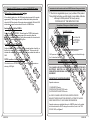
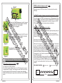
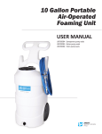
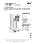
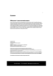
F1 Electrónica S.R.L. F1 Electrónica S.R.L. F1 Electrónica S.R.L. F1 Electrónica S.R.L. F1 Electrónica S.R.L. F1 Electrónica S.R.L. F1 Electrónica S.R.L. F1 Electrónica S.R.L. F1 Electrónica S.R.L. F1 Electrónica S.R.L.
F1 Electrónica S.R.L.
Máximo Paz 1276, (1824) Lanús Oeste.
Telefax: ++54 (11)-4262-6249
Provincia de Buenos Aires
República Argentina
F1 Electrónica S.R.L. F1 Electrónica S.R.L. F1 Electrónica S.R.L. F1 Electrónica S.R.L. F1 Electrónica S.R.L. F1 Electrónica S.R.L. F1 Electrónica S.R.L. F1 Electrónica S.R.L. F1 Electrónica S.R.L. F1 Electrónica S.R.L.
Instalation and User Manual of
Change-over Switch:
DELTA
* Change-over Switches for Injection fitted with
indicator
* Injectors Emulators UNIVERSAL type
* Switches fitted with reserve indicator
* Timing Advance Processors
* Lambda signal emulators
Tel/Fax.: 54-11-4262-6249
www.f1electronica.com.ar
Máximo Paz 1276, Lanús, Bs. As.
12
ENGLISH
ENGLISH
1
Make sure the electrical installation is far
from high voltage cables. SPARK
CABLES MUST BE FACTORY
ORIGINALS OR OF SIMILAR QUALITY.
!
NOTES
Make sure electrical installations are
welded and properly isolated.
NEVER thread the pressure gauge using
your hand. Use a 14mm-fix wrench.
Direct sunlight on the pressure gauge
affects its operation. For example, if the
hood is open, the indicator lights might not
turn on.
!
2
ENGLISH
THE PROPER OPERATION OF THE
CHANGE-OVER SWITCH DEPENDS ON
FOLLOWING THE ABOVE-MENTIONED
INSTRUCTIONS.
ENGLISH
11
Technical Features.
Features
Max.
Tip.
Min.
Unit
15
13.8
10
VOLT
5
--
--
AMPER
5
--
--
AMPER
5
--
--
AMPER
Height
--
22,5
--
mm
Width
--
39
--
mm
Length
--
69
--
mm
Input voltage.
(V+)
Current in GAS
output. (Ig)
Current in PETROL
output. (In)
Fuse as in DIN 72581
Standards.
Troubleshooting: Common Symptoms & Solutions
Symptom
The change-over switch is
not working.
Solution
V Check that the ORANGE cable has +12V with vehicle’s ignition
switch on, and that BLACK cable is properly connected to Ground.
V Check condition of the 5-Amper fuse in electrical installation
If the change-over switch
is in the GAS position, the
vehicle starts but, after 3
seconds approx,it stops.
V Check that the coil negative signal (RED cable) is well
received.
The change-over switch is
not working properly.
V Check that the electrical installation is far from the high voltage
cables.
V Check that the electrical connections are properly welded and
isolated.
F1 Electrónica S.R.L. shall assume no liability for any damage
caused to individuals or things resulting from the manipulation of
the product by third parties not authorized to that effect.
10
ENGLISH
WARRANTY CERTIFICATE
Dear customer:
Congratulations on your purchase of this F1 Electrónica product. All our
products undergo rigorous quality tests. However, if the product features
any kind of defect, please address your installer urgently, who will make
the necessary checkups or will intervene as necessary.
General Warranty Information:
This product is warranted by F1 Electrónica for a period of 12
(twelve) months from the date of installation. Defects in manufacturing and
materials, as well as defects in everything related to the good operation of
the equipment will be covered. Should the product be defective during the
warranty period, F1 Electrónica will repair or replace the defective parts.
Shipping expenses will be borne by the addressee.
Components or accessories not manufactured by F1 Electrónica
will be covered only by the warranties of their respective manufacturers.
This warranty is the only one provided by F1 Electrónica. Therefore, any
other warranty is excluded.
F1 Electrónica shall assume no liability for any damage against
individuals or things resulting from product misfunction, except in the
event of gross deceit or intent. This warranty will be valid only for those
who are not late in payments.
Conditions:
This warranty will only be valid if this certificate is submitted,
which shall be fully filled in, and, enclosed, if necessary, to the purchase
receipt. F1 Electrónica may refuse to recognize this warranty if it is
incomplete or false. This warranty will only be valid if the product was in
good operating conditions at the moment of purchase and its packaging,
intact, as F1 Electrónica is the only one that may warranty its origin.
[ PARA ENTREGAR AL USUARIO ]
ENGLISH
3
Exclusions and Limitations:
Connection Diagram of DELTA Electronic Change-over Switch
a) Maintenance, control, repair or replacement of parts that have
deteriorated after normal use.
b) Damage or malfunctioning resulting from wrong installation, misuse or
use that does not agree with the technical instructions supplied, and any
defect that is not caused by a construction defect, and therefore to the
responsibility of F1 Electronica S.R.L.
c) Products installed, repaired, replaced or changed by individuals not
authorized in writing by F1 Electrónica.
d) Accidents caused by force majeure (i.e.: fire, water, electromagnetic
fields, etc.) not controlled by F1 Electrónica.
Serial Nr.:
(+) (-)
03
G
H
E
02
04
B
A
Date of installation:
J
01
06
05
F
D
07
Vehicle model and brand:
02
C
E
References for the connection diagram of DELTA electronic change-over switch
Fitter Stamp:
4
ENGLISH
[ TO BE PROVIDED TO USER ]
01 ORANGE cable (+12V).
A
Rear view of DELTA change-over switch.
B
MAX. 5A Fuse
02
BLACK cable (GROUND).
C
Pressure gauge with infrared sensor.
03
D
Connection cables to pressure gauge.
RED cable, connection to ignition coil
negative, or ignition module signal, or
ignition signal of the ECU, or RPM signal of
the ECU. This signal must have a minimum
amplitude of 5V.
E
Chassis GROUND.
F
PETROL electrovalve (CARBURETOR mode).
04 BLUE cable.
G
Ignition coil, or ignition module, or ECU.
05 WHITE cable.
H
Gas electrovalve.
06 YELLOW cable.
J
+12V under ignition swtich.
07 GREEN cable.
ENGLISH
9
Operation of DELTA change-over switch in CARBURETOR mode
GAS position of change-over switch
If the vehicle’s ignition is on, the GAS electrovalve is opened for 3 seconds
approxmately. This change-over switch is fitted with a safety device that
closes the GAS electrovalve if the engine stops accidentally. While the GAS
electrovalve is open, the two-colour led is on in a GREEN color.
Instructions for the Connection and Use of DELTA Electronic Change-over Switch
F1 Electrónica congratulates you on your purchase of this product.
Through high technology, we offer smaller, more reliable, attractive
and easy to install products.That is why we say:
TECHNOLOGY AT THE SERVICE OF CNG.
Description of Change-over Switch Front View
Switch-over from GAS to PETROL
3-position switch
Position the switch on PETROL. This will open the PETROL electrovalve
while the GAS electrovalve remains open for 4 seconds to allow the
carburetor chamber to be filled in. During these seconds, the two-colour led
blinks in RED and there is a GREEN light on.
Two-colour led
Red PETROL
Green GAS
Change-over from PETROL to GAS
Position the switch on the NEUTRAL position (central position of switch), so
that the fuel remaining in the carburetor is consumed. The two-colour led
indicates this condition blinking with a RED light, then position the switch on
GAS.
PETROL position of change-over switch
The vehicle runs on PETROL at all times. The two-colour led remains on
showing a RED light.
Leds indicating GAS pressure
GAS pressure is indicated through 4 leds. The reserve is indicated through
the ¼ intermitent led.
Operation of DELTA Change-over Switch
THIS CHANGE-OVER SWITCH IS DESIGNED FOR VEHICLES FITTED WITH
ELECTRONIC INJECTION AS WELL AS VEHICLES FITTED WITH
CARBURETOR AND ORIGINAL ELECTRONIC IGNITION, BOTH WITH CNG
EQUIPMENT.
*DEFINITION OF THE OPERATION MODE*
Operation modes are:
1) CARBURETOR mode.
2) DECELERATION INJECTION mode.
3) ACCELERATION INJECTION mode.
ALL DELTA CHANGE-OVER SWITCHES ARE PROVIDED BY
MANUFACTURER IN INJECTION MODE WITH AUTOMATIC CHANGEOVER FROM PETROL TO GAS DURING DECELERATION.
Operation modes are established through a JUMPER placed on the printed
circuit board inside the DELTA change-over switch unit, next to the TWOCOLOUR LED, see Figure 1.
8
ENGLISH
ENGLISH
5
Figure 1
PETROL position of change-over switch
The vehicle runs on PETROL at all times. The two-colour led is on with a
RED light.
AUTOMATIC position of change-over switch (central position of switch)
JUMPER
If you place the JUMPER between pins 1 and 2, the mode
is defined as INJECTION WITH AUTOMATIC CHANGEOVER FROM PETROL TO GAS DURING
DECELERATION, see Figure 2.
Figura 2
If you place the JUMPER between pins 2 and 3 the mode
is defined as INJECTION WITH AUTOMATIC CHANGEOVER FROM PETROL TO GAS DURING
ACCELERATION, see Figure 3.
Figura 3
If you remove the JUMPER, the mode is defined as
CARBURETOR, see Figure 4.
Figura 4
Operation of DELTA Change-over Switch in INJECTIÓN mode
GAS position of change-over switch
The vehicle runs on CNG at all times.
If the vehicle’s ignition switch is turned on, the GAS electrovalve is opened
for approximately 3 seconds. This change-over switch is fitted with a safety
device that closes the GAS electrovalve if the engine stops accidentally.
While the GAS electrovalve is open, the two-colour led is on with a GREEN
colour.
6
ENGLISH
The vehicle starts on PETROL and changes-over to GAS automatically either
during acceleration or deceleration when pre-established RPM are exceeded.
This change-over switch is programmed for automatic change-over at 2500
RPM during deceleration for 4-cylinder vehicles with distributor.
Regulating the automatic change-over system.
The indicator must be placed in SETTING mode (special operating mode) as
follows:
Place the indicator switch on the central position, then turn the vehicle’s
ignition switch on and, within the next 10 (ten) seconds, repeat the following
sequence 3 (three) times:
Move change-over switch to PETROL position.
Move change-over switch to central position (AUTOMATIC).
Make sure the change-over switch is left on the central position. The indicator
will be on the SETTING mode and this will be indicated by the ¼ and full leds
that will be on. At this moment, always with the ignition switch on, start the
vehicle and keep accelerated at the desired RPM for automatic change-over.
Move the change-over switch to the GAS position and then to the central
position so that these revolutions are memorized. The change-over switch
will engage the ½ and ¾ leds for a moment indicating the revolutions are
succefully programmed.
At this moment, (with the change-over switch on central position) you may
test programmed RPM by accelerating the vehicle and seeing that the twocolour led changes from RED to GREEN when the programmed RPM are
exceeded. Turn the ignition switch off, and from now on, it is ready to operate
normally.
EXPLAINING DIAGRAM:
Ignition on
swithc in
automatic.
N
N
A
A
PETROL position.
N
A
N
Central switch position.
A
SETTING
O.K.
10 sec.
ENGLISH
7