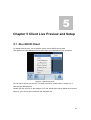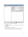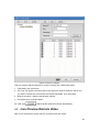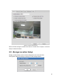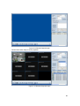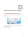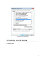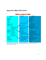
1
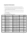
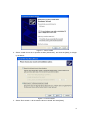
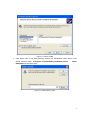
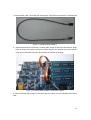
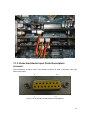
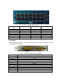
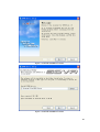
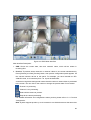
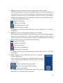
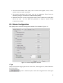
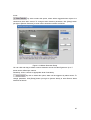
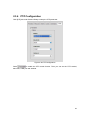
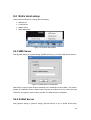
Super DVR Software V1.0 User Manual (Version 1.0) June. 2009 Content IMPORTANT INFORMATION ...............................................................................3 CHAPTER 1 HARDWARE & SOFTWARE INSTALLATION..................................5 1.1 HARDWARE INSTALLATION ....................................................................................5 1.1.1 1.1.2 1.1.3 1.2 Hardware Driver Installation...................................................................................5 Connection Wizard ..............................................................................................12 Video And Audio Input Ports Description..............................................................15 SOFTWARE INSTALLATION ..................................................................................19 CHAPTER 2 SYSTEM CONFIGURATION .........................................................24 2.1 2.2 2.3 OVERVIEW ........................................................................................................24 SYSTEM CONTROL PANEL ..................................................................................29 CAMERA SETUP .................................................................................................29 2.3.1 2.3.2 2.3.3 2.3.4 2.3.5 2.3.6 2.3.7 2.4.1 2.4.2 2.4.3 2.4.4 Preview Configuration .........................................................................................31 Record Configuration...........................................................................................32 Alarm Configuration.............................................................................................34 Color Configuration .............................................................................................40 Schedule Configuration .......................................................................................42 PTZ Configuration ...............................................................................................46 System setup ......................................................................................................47 SMS Server.........................................................................................................49 E-Mail Server ......................................................................................................49 Mobile Server ......................................................................................................50 Setup Disk Sleep.................................................................................................51 CHAPTER 3 PLAYBACK ....................................................................................52 3.1 3.2 OVERVIEW ........................................................................................................52 MAIN FUNCTIONS ..............................................................................................53 3.2.1 Browse Picture ..........................................................................................................53 3.2.2 Zoom ........................................................................................................................54 3.2.3 Play mode .................................................................................................................55 3.2.4 Burn CD ....................................................................................................................57 3.3 3.4 3.5 PLAY CONTROL TOOLS.......................................................................................58 SMART SEARCH.................................................................................................60 INSTANT REPLAY................................................................................................61 CHAPTER 4 SYSTEM MANAGEMENT .............................................................63 4.1 4.2 OVERVIEW ........................................................................................................63 USER MANAGEMENT ..........................................................................................64 4.2.1 4.2.2 4.3 TOOLS ..............................................................................................................68 4.3.1 4.3.2 4.3.3 4.3.4 4.4 Local User Management......................................................................................64 Remote User Management..................................................................................66 E-Map Editor .......................................................................................................68 E-Map Browser ...................................................................................................70 Control Relay Output ...........................................................................................71 Full Screen on Alarm ...........................................................................................72 DISK MANAGEMENT ...........................................................................................72 4.4.1 4.4.2 2.4.5 Disk Access Log..................................................................................................72 Local Disk Space.................................................................................................73 Digital Matrix .......................................................................................................74 1 4.5 4.6 4.7 LOG MANAGEMENT ............................................................................................77 MATRIX CONTROL..............................................................................................77 COMMUNICATION ...............................................................................................77 4.7.1 Voice Talk..................................................................................................................77 4.7.2 Send SMS.................................................................................................................78 4.8 INTERNET DEVICE MANAGER ..............................................................................79 CHAPTER 5 CLIENT LIVE PREVIEW AND SETUP...........................................81 5.1 5.2 5.3 5.4 5.5 5.6 RUN SDVR CLIENT ...........................................................................................81 CONFIGURATION AT SDVR CLIENT......................................................................82 LIVE PREVIEW REMOTE VIDEO ...........................................................................84 REMOTE CAMERA SETUP AT CLIENT....................................................................85 STORAGE LOCATION SETUP ...............................................................................87 PLAYBACK AT SDVR CLIENT...............................................................................88 5.6.1 5.6.2 Local playback ....................................................................................................88 Remote playback.................................................................................................88 CHAPTER 6 IE LIVE PREVIEW AND SETUP....................................................90 6.1 6.2 6.3 DISABLE THE MEMORY PROTECTION IN IE ..........................................................90 ENTER THE SERVER IP ADDRESS .......................................................................92 LIVE VIEW REMOTE VIDEO...................................................................................93 APPENDIX I MENU STRUCTURE .....................................................................95 2 Important Information For optimal performance of your system, it is important to follow these recommendations. 1. It is strong recommended that dividing your hard disk into two partitions(C: and D:) at least. The first partition will be used to install Windows OS and other applications, and left partitions will be used to store recording files. 2. Please choose NTFS (NT File System) as the file system format when formatting hard disk. 3. Please use appropriate motherboard and video card. Contact with our support engineers if you have questions. 4. Please use industrial case. Recommended System Requirements Per System Graphics HW Graphics SW CPU Total Memory 1x4ch NVIDIA 7xxx series, 8xxx series ATI Radeon 2xxx series Intel 945G chipset NVIDIA 7xxx series, 8xxx series ATI Radeon 2xxx series Intel 945G chipset NVIDIA 7xxx series, 8xxx series ATI Radeon 2xxx series Intel 945G chipset NVIDIA 7xxx series, 8xxx series ATI Radeon 2xxx series Intel 945G chipset NVIDIA 7xxx series, 8xxx series ATI Radeon 2xxx series Intel 945G chipset NVIDIA 7xxx series, 8xxx series ATI Radeon 2xxx series Intel 945G chipset NVIDIA 7xxx series, 8xxx series ATI Radeon 2xxx series Intel 945G chipset NVIDIA 7xxx series, 8xxx series ATI Radeon 2xxx series Intel 945G chipset NVIDIA 7xxx series, 8xxx series ATI Radeon 2xxx series Intel 945G chipset NVIDIA 7xxx series, 8xxx series ATI Radeon 2xxx series Intel 945G chipset DirectX 9.0 or higher, with hardware acceleration for DirectDraw and Direct3D DirectX 9.0 or higher, with hardware acceleration for DirectDraw and Direct3D DirectX 9.0 or higher, with hardware acceleration for DirectDraw and Direct3D DirectX 9.0 or higher, with hardware acceleration for DirectDraw and Direct3D DirectX 9.0 or higher, with hardware acceleration for DirectDraw and Direct3D DirectX 9.0 or higher, with hardware acceleration for DirectDraw and Direct3D DirectX 9.0 or higher, with hardware acceleration for DirectDraw and Direct3D DirectX 9.0 or higher, with hardware acceleration for DirectDraw and Direct3D DirectX 9.0 or higher, with hardware acceleration for DirectDraw and Direct3D DirectX 9.0 or higher, with hardware acceleration for DirectDraw and Direct3D Intel dual-core 2.4 GHz or equivalent 1GB Intel dual-core 2.4 GHz or equivalent 1GB Intel dual-core 2.4 GHz or equivalent 1GB Intel dual-core 2.4 GHz or equivalent 1GB Intel dual-core 2.4 GHz or equivalent 1GB Intel dual-core 2.4 GHz or equivalent 1GB Intel dual-core 2.4 GHz or equivalent 1GB Intel dual-core 2.4 GHz or equivalent 1GB Intel dual-core 2.4 GHz or equivalent 1GB Intel dual-core 2.4 GHz or equivalent 1GB 2x4ch 3x4ch 4x4ch 1x8ch 2x8ch 3x8ch 4x8ch 1x16ch 2x16ch 3 3 x16ch 4 x16ch NVIDIA 7xxx series, 8xxx series ATI Radeon 2xxx series Intel 945G chipset NVIDIA 7xxx series, 8xxx series ATI Radeon 2xxx series Intel 945G chipset DirectX 9.0 or higher, with hardware acceleration for DirectDraw and Direct3D DirectX 9.0 or higher, with hardware acceleration for DirectDraw and Direct3D Intel dual-core 3.0 GHz or equivalent 2GB Intel dual-core 3.0 GHz or equivalent 2GB Notice: 1 Memory buffer allocation requirement is 20MB per channel. Up to 40MB per channel can be allocation. Please visit the website http://www.skyvision.com.cn to get more support. 4 Chapter 1 Hardware & Software Installation 1.1 Hardware Installation 1.1.1 Hardware Driver Installation Here is a demo installation of DS-40xx Series DVR card. Before installing hardware, be sure that the computer is power off. To install the DS-4008HCI card to your PC, follow these steps: 1. Insert the DS-4008HCI card into an empty PCI slot, and fasten it. 2. Turn on your PC and start Windows OS. There are two ways to install the card driver. One is according the Hardware Installation Wizard to install the driver, and the other is run the Driver Install.exe directly to install the driver automatically. Here is the first method: 1. A Hardware Installation Wizard for this newly installed card will appears, when you start the computer after inserting the card successfully. 5 Figure 1-1. Driver Install1 2. Select “Install from a list or specific location (Advanced)”, and click the [Next], it will pop up as below: Figure 1-2. Driver Install2 3. Select “Don’ t search. I will choose the driver to install”and click [Next]: 6 Figure 1-3. Driver Install3 4. Click [Have Disk… ] and click [Browse]. Choose the DS4008HCI card’ s driver in the SDVR software folder: C:\Program Files\SDVR\Drivers\DS4000_Series. Select DS40xxDrv.inf. And Click [OK]. Figure 1-4. Select driver’ s path. 7 Figure 1-5. Select right driver. 5. Select “DS 40xxHC/HCS/HC+/HF/MD Series”and click [Next] to install the driver. Figure 1-6. Select the driver 8 6. Click [Next] with the default. It will popup the window as below to show the driver installed successfully. Click [Finish] to complete driver installation and restart the computer. Figure 1-6. Driver Installed successfully Here is the second method: 1. A Hardware Installation Wizard for this installed card will appears. Ignore the wizard window. 2. Go to SDVR software’ s folder C:\Program Files\SDVR\Drivers\DS4000_Series, to find the driver application Driver Install.exe, double click to run it. A Driver Installer dialog box appears. Figure 1-7. Driver Install 2. Click [Install or Update Driver] to install/update the driver. Window OS will pop up a window ,it is as following : 9 Figure 1-8. Hardware Installation On Windows XP 3. Click [Yes]/[Continue Anyway] to continue the hardware installation, If there are more than one board are inserted in the PC or more than one DSP in one board, the operation system will remind you of repeating the above process. 4. When the installation is done, this message will appear: Driver Installed Successfully! Figure 1-9. Driver Installed Successfully 5. Click [OK] to quit the driver installation. At last you will find the detail information of the board on the windows Device Manager (it depends on the total number of boards you installed in the computer). 10 Figure 1-10. System Properties –Device Manager Figure 1-11 Driver’ s installed on Windows XP 11 1.1.2 Connection Wizard The following card and cable should be ready for connection: 1. DS-40xxHCI card: Figure 1-12 DS-40xxHCI card front view Figure 1-13 DS-40xxHCI card back view 2. External video input and audio input cable. Red cables are for video input, and the white ones are for audio input: 12 Figure 1-14 Video & Audio Input Cable 3. Internal audio connection cable between DS-40xxHCI compression boards: Figure 1-15 Internal Audio Cable 1 13 4. Internal audio cable, connecting the DS-40xxHCI compression board with PC motherboard: Figure 1-16 Internal Audio Cable 2 5. Boards internal audio connection: Connect audio output of first HCI board with the audio input of second HCI board, connect the audio output of the second HCI board with the audio input of the third HCI boar, the rest may be deduced by analogy. Figure 1-17 Internal Audio Cables Connection Example 6. Connect the last audio output of HCI board with the CD IN of PC motherboard /PCI sound card: 14 Figure 1-18 Internal Audio Cables Connection Example 1.1.3 Video And Audio Input Ports Description DS-4004HCI The DS-4004HCI provides a DB 15-pin female connector to input 4 channels’video and audio signal (DB1). 9 15 1 8 Figure 1-19 15-pin DB port description of DS-4004HCI 15 Pin 1 2 3 4 5 6 7 8 9 10 11 12 13 14 15 Signal Description Video 1 Video 2 Video 3 Video 4 Audio 1 Audio 2 Audio 3 Audio 4 GND GND GND GND GND GND GND DB1 pins description The DS-4004HCI also provides optional internal PIN for video and audio input (DB2) . Figure 1-20 DB2 of DS-4004HCI 16 Figure 1-21 DB2 of DS-4004HCI Description Pin 1 3 5 7 9 11 13 15 Pin Description Video 1 2 Video 2 4 Video 3 6 Video 4 8 Audio 1 10 Audio 2 12 Audio 3 14 Audio 4 16 DB2 pins description GND GND GND GND GND GND GND GND DS-4008HCI The DS-4008HCI provides two DB 15-pin female connectors to input 8 channles’video and audio signal .(DB1 and DB2) DB1 DB2 Figure 1-22 DB1 and DB2 Ports of DS-4008HCI Pin 1 2 3 4 5 6 7 8 9 10 11 12 13 Signal Description Video 1 Video 2 Video 3 Video 4 Audio 1 Audio 2 Audio 3 Audio 4 GND GND GND GND GND 17 14 15 GND GND DB1 pin description Pin 1 2 3 4 5 6 7 8 9 10 11 12 13 14 15 Signal Description Video 5 Video 6 Video 7 Video 8 Audio 5 Audio 6 Audio 7 Audio 8 GND GND GND GND GND GND GND DB2 pin description The DS-4008HCI also provides optional internal PIN for video and audio input (DB3 and DB4). Figure 1-23 DB3 and DB4 Ports of DS-4008HCI 2 1 16 2 16 8 1 8 18 Figure 1-24 DB3 and DB4 Ports of DS-4008HCI Pin 1 3 5 7 9 11 13 15 Description Pin Video 1 2 Video 2 4 Video 3 6 Video 4 8 Audio 1 10 Audio 2 12 Audio 3 14 Audio 4 16 DB3 pin description Description GND GND GND GND GND GND GND GND Pin 1 3 5 7 9 11 13 15 Description Pin Video 5 2 Video 6 4 Video 7 6 Video 8 8 Audio 5 10 Audio 6 12 Audio 7 14 Audio 8 16 DB4 pin description Description GND GND GND GND GND GND GND GND 1.2 Software Installation 1. Insert the installation CD into the CD-ROM drive. 2. In the installation CD folder, locate the SDVR.exe, double click it to run this application, then the startup window appears: 19 Figure 1-25 SDVR Installation Process Figure 1-26 SDVR Installation Process 20 Click [Next] and use default installation directory. 3. The next step of installing, it will prompt you to install the board driver. Click [Next], it will pop up the card’ s driver for each type card. You can choose the right driver to install. Figure 1-26 SDVR Installation Process 4. Click [Next], it will ask you to select the dvr card series. It will pop up the Board Wizard window. 21 Figure 1-27 SDVR Installation Process 5. The Board wizard window is as below, the default is DS Series DVR cards. You can select the right card tryp you’ re using. And then Click [OK]. 22 Figure 1-28 Board Wizard 6. Follow the on-screen instructions to complete the installation. It will create a shortcut on desktop. Note: To uninstall the software, please go to Start Program SDVR Server Uninstall SDVR Server. And delect the SDVR folder in C:\Program Files\SDVR Server to uninstall SDVR completely. 23 Chapter 2 System Configuration 2.1 Overview Follow these steps to begin to configure your system: Step 1: The picture followed will appears when you start up the SDVR system by double-click the shortcut of SDVR in the desktop. It means the system is loading. Figure 2-1 System Startup Logo If you haven’ t register the card, it will show pop up the warning message and the card series number. Copy the number and send it to our sale to get the licence file. 24 Figure 2-2 Registration information Copy the licence file to C:\Program Files\SDVR Server\lic. If the license file is right, it will not pop up the Registration information window when it start up. Step 2: Then you will be prompted to enter the username and password: ■ Username: super ■ No Password Figure 2-3 SDVR Authorization By default, the Username is “super”, and no password. Usage Tips: you can modify the password in this menu: [Others] - [User Management] [Local] Step 3: When entered correct username and password, you will see the main interface as follows: 25 Figure 2-4 SDVR Main Interface Main Interface Description: 1. OSD: Shows the current date, time and camera’ s name, which will be written in recording files. 2. Preview: To preview all the channels’or cameras’videos in one screen simultaneously. Press [Preview] to unfold [Preview] button, then preview configuration panel appears. All the camera numbers will list in this panel. For example, you have inserted two DS4008HCI cards, so 16 numbers (from 1 to 16) will be listed here. A number in bright blue background means that this number’ s camera video is previewed in the screen. You can click on the number to change the preview state of one camera. : Channel 1 is priviewing. : Channel 1 isn’ t previewing. : Select all the camera to preview. : Stop all the camera previewing. For detailed information and configurations about preview, please refer to 2.3.1 Preview Configuration. Note: System supports preview up to 64 cameras in one divided screen at the same time. 26 3. Record: It shows and enable control the recording status of all the cameras. Press [Record] button to unfold record configuration panel, in which the recording status of all the cameras shows. A number in bright blue background means that this number’ s camera is in recording. To start or stop recording a camera, just click on the number to change the recording status of one camera.When a camera is in recording or recorded, you can find recording files in the disk. : Channel 1 is recording. : Channel 1 isn’ t recording. : Select all the camera to record. : Stop all the camera recording. For detailed information and configurations about record, please refer to 2.3.2 Record Configuration. 4. Alarm: Here you can control the alarm detection for each camera. Press [Alarm] button to unfold alarm configuration panel, in which the alarm detection status of all the cameras shows. A number in bright Blue background means that this number’ s camera is in alarm detection status.To start or stop alarm detection of a camera, just click on the number to change the status of one camera. : Channel 1 is detecting. : Channel 1 isn’ t detecting. : Channel 1 is alarming. : Select all the camera to detect. : Stop all the camera detecting. For detailed information and configurations about alarm, please refer to 2.3.3 Alarm Configuration. 5. Color: Adjust the color configuration here, such as brightness, contrast, saturation, hue. Press [Color] button to unfold color configuration panel. Drag the slider to change the parameter, and it will take effect in the video picture at once. : Set the color setting back to the default. : Copy the color setting to all the channels. : Save the color setting. For detailed information and configurations about color pattern, please refer to 2.3.4 Camera Color Configuration. 27 6. Matrix: You can output the video to monitors beside SDVR by using digital matrix card. Here will list all the output groups that added in [Digital Matrix]. Click to circulate the groups. For detailed information and configurations about color pattern, please refer to 2.4.1 Digital Matrix. 7. PTZ Control: Control the movement of your PTZ camera. Click button to unfold the panel and enter the control interface. It will show the PTZ interface as right. : Call out the preset setup window, and setup the preset for each channel. : Configure the aux function. : Circulate the preset automatically. : Setup the PTZ’ s speed. : Enable the ptz direction call . Then click each direction you want to control the camera. You also can adjust the PTZ camera’ s Iris, Focus and Zoom. For detailed information and configurations about color pattern, please refer to 2.3.6 PTZ Configuration. 8. System Control Panel: Control the main system functions. For detailed information and configurations, please refer to 2.2 System Control Panel. 9. Active Time: Displays the current date and time, time length that this system has been run. 10. Login/Lock System: Login the system or exchange user. You also can lock the system when you are away, so other people do not enter the system. 11. Screen Division: Choose screen divisions or layout modes at here. 12. Exit System: Exit the system. 28 2.2 System Control Panel Figure 2-5 System Control Panel 1. System Setup: Configure system parameters, including camera preview settings, alarm settings, schedule setting, and system server settings, etc.; For detail information, please refer to 2.3 Camera Setup and 2.4 System Setup. 2. Schedule: Press [Schedule] button to start or stop predefined schedule. 3. Playback: Playback the local record files or the record files at remote SDVRS. For detail information, please refer to Chapter 3 Playback Configuration. 4. Monitor: Listen to the real time audio. Press this button to turn on / off this option. 5. Capture: Click [Capture] to snapshot current picture. Note: You can go to [Playback] [Browse Picture] to preview the captured picture. 6. Circulation: Preview the video images circularly. Press [Circulation] to configure it: Figure 2-6 SDVR Circulation Configuration 7. Others: to manage your SDVR system, such as user management, disk management. For detail information about system management, please refer to Chapter 4 System Management. 2.3 Camera Setup Click [System Setup], then choose [Camera Setup] submenu, you will enter the SDVR 29 Camera Setup interface as follows: Figure 2-7 SDVR Camera Setup Window The left column lists the camera numbers and their names. You can choose to configure one camera’ s parameters by clicking to select the camera number. The right column shows all the functions and parameters related to camera setup. You can specify detailed parameter to configure each camera. There are six tabs under [Camera Setup]: : Specify the parameters about how to preview the camera’ s video. : Specify the settings about record quality, storage parameters, networking transmission method, and so on. : Customize alarm trigger types, corresponding actions and so on. : Create and modify display color patterns here. : You can define and save automatic work schedules here : Specify the setting of PTZ here, such as product model, baud rate, COM port and so on. 30 2.3.1 Preview Configuration Click [Preview] tab in the right column to enter the Preview Configuration Interface. See details in Figure 2-8. Figure 2-8 SDVR camera preview configuration interface 1) : Describes the camera’ s name here. Camera name should be less than 20 characters. 2) : Select this option to display camera name on the video picture. 3) : Select this option to display date and time on the video picture. 4) : Select this option to ensure camera information such as camera name, date and time good visibility either in weak or strong light video. 5) : Users can set a specific area as mask area to prevent 31 important information to be seen by other people, for example, preventing password input area to be seen in the video. You can drag a rectangular area as the mask area by keep clicking left key on mouse. 6) 7) 8) : User can change the background image for the channel. : Click it to recover back to default preview configuration. : Click it to enter Select channel as figure 2-7. You can click [select all] to select all the cameras or channels, or you can click the channel number to select the camera you want to copy configuration to, then press [OK] or [Cancel] to apply or cancel these changes. Figure 2-9 Select channel Interface 2.3.2 Record Configuration Click [Record] tab to enter Record Configuration interface. See details as Figure 2-10. 32 Figure 2-10 Recording Configuration Recording Quality: Set record Resolution: click to choose from CIF, 2CIF, DCIF or D1 (4CIF) under Recording Quality. Set record quality: click to choose from Highest, Level1, Level2, Level3, Level4 or Level5 as need. Set frame rate: set the appropriate Frame Rate per Second by using up or down arrow under Recording Quality. Record audio: To record audio and video simultaneously, click to select [Record Audio] under Recording Quality. Storage: Set Maximum Recording Time: By default, every 30 minutes’video will be created to a video file. You can change the value here to control the video file size. Enforce Storage limits: By click to select this checkbox, you can set a recording rate upper limit. It is recommended to use in small hard disk circumstance. Networking: Dual Stream: click to choose this checkbox to enable Dual stream function. 33 Set network transmitted video quality: click to choose from Highest, Level1, Level2, Level3, Level4 or Level5 as needed. Set network transmitted video frame rate: set the appropriate Frame Rate per Second by using up or down arrow under Recording Quality. Maximum Files Size: choose an appropriate value to set the maximum recording files size in an hour. You can adjust this parameter to adapt to network media transmission condition. 2.3.3 Alarm Configuration Click [Alarm] tab to enter Alarm Configuration interface. See details as Figure 2-11. Figure 2-11 Alarm configuration interface 1. Type There are three alarm trigger types can be chosen from, Video Signal Loss, Motion Detection and Sensor Alarm. : By click to select this option, alarm will be triggered when video signal 34 is lost. : By click to select this option, alarm will be triggered when objects in a certain area have been moved. To change motion detection parameter, click [Setup] button just right to [Motion Detection] to enter motion detection interface as follows: Figure 2-12 Motion Detection Setup You can click and drag to define a motion detection area in the video figureture. Up to 7 areas can be defined per camera. Sensitivity: click to choose an appropriate level of sensitivity. : By click to select this option, alarm will be triggered by alarm sensor. To change parameter, click [Setup] button just right to [sensor Alarm] to enter Sensor Alarm interface as follows: 35 Figure 2-13 Sensor Alarm Configuration Here lists all the sensors connected to this SDVR system. You can choose the sensors by clicking the sensor numbers or click [Select All] button, then press [OK] to apply the setting. The sensors should be connected to an alarm box which is connected to computer through serial line. The alarm box is used to transform signals between and computer or SDVR. 2. Action Action defines actions or behavior when alarms are triggered. There are eight action types can be chosen from in this system. : Select this option, the channel will be triggered to audible alert when alarm. Click [setup] to configure parameters. Figure 2-14 Audible Alert Configuration 36 In the left column, choose a trigger type when you want alarm to act on. In the right column, click open file icon to choose an audio file that you want to play for a certain types of alarm. And click speak icon to play this audio file. : Select this option, the channel will go to record when alarm. Click [Setup] to configure parameters. Figure 2-15 Recording Action Configuration You can choose the cameras or channels by clicking the camera numbers or click [Select All] button, then press [OK] to apply the setting. : Select this option, the channel will call out the set PTZ preset when alarm. : To choose to output or relay alarms to other device, just click to select [Output to Relay], then click [Setup] to configure parameters. 37 Figure 2-16 Output to Relay Alarm Action Configuration You can select appropriate alarm boxes to be co-worked with this alarm. : Select this option to choose to notify network client. Click [Setup] for configuration: Figure 2-17 Notify to Network Client Alarm Action Configuration Under Notify Network Client, you can add, edit or delete a certain IP address to be notified when there is an alarm signal. Clicking to select Notify Connected Client to notify to all connected clients. 38 : Select this option to send short messages to certain users when the channel alarmed. Click [setup] to configure a SMS contents and user list. Figure 2-18 Send Short Message Alarm Action Configuration You can compile the SMS contents in [Contents] field, and add, edit or delete a phone list in [Phone List] field. : Select this option to send email to the user. Click [setup] to configure. 39 Figure 2-19 E-Mail Alarm Action Configuration It can send the Contect and the Jpg file to the defined email. : Select this option to snapshot when the channel alarmed. Click [Setup] to configure: Trigger Interval: define the snapshot frequency. 3. Time : Set the length of alarm duration time. System will continue output alarm information in this length of time when the actual alarm is stopped. : Set the length of post alarm record time, which is after alarm duration is stopped. Click to restore the configuration to default. And you can also copy these configurations to other cameras by click [Copy to] button. 2.3.4 Color Configuration Click [Color] tab under Camera Setup to configure camera’ s color. In some circumstance, video quality fluctuated by outside light changes or caused by camera 40 itself. To counteract this effect, we can manually set a color patter schedule. Figure 2-20 Color Configuration Select to enable the designed color pattern. You can add, edit or delete color pattern at here.To add or edit a color pattern, click button. 41 Figure 2-21 Add or Edit color pattern You can set a start time that let color pattern to be in effect. And adjust the slide bar to get the appropriate color pattern. 2.3.5 Schedule Configuration We can add, edit or delete a schedule at here. 42 1. Add Schedule Click the [Add] button, then you can select the record type. Figure 2-22 Add Schedule Configuration There are total 13 recording patterns can be chosen from: Recording: recording only, and doing 7X24 hours. Motion + Sensor; set alarms triggered by motion detection and sensor. Motion + sensor + Video Loss + Recording: recording all the time, and set alarms triggered by motion detection, sensor and video loss at the same time. Motion Detection: set alarms triggered by motion detection; Motion + Recording: recording all the time, and set alarms triggered by motion detection; Sensor: set alarms triggered by sensor only. Sensor + Recording: recording all the time, and set alarms triggered by sensor. Video Loss: set alarms triggered by video loss. Video Loss + Recording: Recording all the time, and set alarms triggered by Video loss. 43 Motion + Video Loss: set alarms triggered by motion detection and Video loss; Motion + Video Loss + recording: recording all the time, and set alarms triggered by motion detection and Video loss. Motion + Sensor: set alarms triggered by motion detection and sensor Motion + Sensor+ recording: recording all the time, and set alarms triggered by motion detection and sensor. 2. Copy Parameters to Other Days Copy these configuration to other weekdays, click right to [Day], and choose appropriate days you want to copy to. Figure 2-23 Copy Schedule Configuration to Other Weekdays 44 3. Save Schedule Click [Save] button to save schedule configurations and then click [OK] to exit window. Figure 2-24 Save Schedule 4. Execute the Schedule Exit the schedule setup, the schedule will start automatically. Or click Schedule button of the control panel to start / stop predefined schedule. [Schedule] button Figure 2-25 Start or Stop a schedule Note: You can also click the [Schedule] button to stop running schedule. 45 2.3.6 PTZ Configuration Click [PTZ] tab under Camera Setup to setup the PTZ parameter. Figure 2-26 PTZ Configuration Select to enable the PTZ control function. Then you can set the PTZ’ s model, baud rate, COM port and address. 46 2.3.7 System setup 1) Video Format:choose the video format: PAL and NTSC 2) Storage Drivers:select storage drivers. 3) Use Overlay: Enable overlay when choose this option 4) Enable Instant Replay: Select this option, SDVR will support instant replay when preview. Just select the channel when it is preview, right click the mouse, select Instant Playback, and select the time you wanted to replay. It will pop up the instant playback window. 5) As Client Simultaneously: Select this option and save it. The SDVR sever will run as client simultaneously. You can add other SDVR site to manager at SDVR Server. 6) Display Login window when OS starting up. 7) Secure Desktop: Select this option to secure the desktop. Some OS system keys will be disabled, including “Win+D”, “Win”, etc. 8) Auto Restart System Every: Set a time that the OS system will be restarted automatically 9) Auto Start Software: Select this option, the SDVR system will run automatically after OS start. If your OS is prevented by username, you can input the username and password 47 here. 10) Web port: It is the port for IE access The default is 80. 11) Network Port: It is video port for communication with client. You must map it when you access with SDVR client in WAN. The default is 65000. 12) Center Timeout: The default is 10000ms. 13) Client Timeout: The default is 8000ms. 14) Update SDVR IP to Center Interval: The default is 5 minute. It will update SDVR IP to the center management system when it is connected. 15) Upload video file to center 16) Real Internet Address: Show SDVR’ s real internet address. 48 2.4 Extra local setup There are three submenus under [Extra local setup] : SMS Server E-mail Server Mobile Server Setup Disk Sleep Figure 2-27 System Setup Menu 2.4.1SMS Server Click [System Setup] [System Setup] [SMS Server] to go to SDVR SMS server window. Figure 2-32 SMS Server Configuration SMS server is used to send the short message to the mobile phone when alarm. You need to prepare one hardware device: SMS module. Connect the module to the PC. Select the right COM Port. And type the service center number. The SMS Server is completed. 2.4.2 E-Mail Server Click [System Setup] [System Setup] [E-mail Server] to go to SDVR email server 49 window. Figure 2-33 E-Mail Server Window E-mail server is used to send email when alarm. You can type your email address and SMTP server at here. If the mail server need authentication, please click and select [Server requires authentication], and then input appropriate account name and password. 2.4.3 Mobile Server Click [System Setup] [System Setup] [RTSP Server] to go to SDVR RTSP server window. 50 Figure 2-34 RTSP Server Window RTSP Server is used for mobile monitor. Option: Configure the mobile parameters: ports, bit rate and so on. User: The user is used for mobile access. It must be added in the [User Management] [Remote User]. Register Information: The unregistered version only can preview 3 minutes for each time in mobile phone. You can copy the Machine ID and send it us to get the license file. 2.4.4Setup Disk Sleep If you have more than one disk, then you can set it, the disks will stop work if the disk have no data read or write for the time as you set in it. 51 Chapter 3 Playback 3.1 Overview Click [Playback] button To enter Playback interface. [Playback] button Figure 3-1 Playback button System support playing multiple channels’videos in divided screen simultaneously. Below is a snapshot picture of four channels’playback: 52 Figure 3-2 Four channels’playback demo 3.2 Main Functions In the centre right corner, you will see playback tools as below: Figure 3-3 Playback modes 3.2.1 Browse Picture Browse picture function is used to preview the channels’pictures captured. Follow four steps to browse pictures. Step 1: Click Capture when preview or click snapshot when playback. Step 2: Click [Browse pictures] to go to Browse Picture window. Step 3: Select a day. Step 4: Use zoom in or zoom out tools to see the picture. 53 Figure 3-4 Browse Pictures 3.2.2 Zoom Zoom function is used to zoom in the video when it is playback. Click [Zoom] button, it will pop up a zoom window: Figure 3-5 Zoom Interface 54 Then, click to drag an area on the video screen that you want to zoom in. Click to drag this rectangular to select an area Figure 3-6 Zoom Demo Click [zoom] button again to exit zoom mode. 3.2.3 Play mode There are two playback modes in playback function: Time-Line Mode and File Mode. Play mode function is used to switch these two modes. The default playback mode is Time-Line mode. 55 1. Time-Line Mode: 1. Select the date 4. Click the [Play] button 2. Select the channel 3. Set the timeline Figure 3-7 Playback Interface Following 4 steps to playback in time-line mode: Step1: Click to choose a day that you want to playback in the calendar located in the top right corner of the interface. Step2: Click to select channles that you want to playback in the down left corner of the interface. Step3: Use the arrows to set the start time as bellows. Once set a time, there will display a red upright line which is the start timeline to playback. 1. Using the right and left arrow to set the start minute for playback. 2. Using the right and left arrow to set the start hour for playback. 3. Click to set the start timeline. 56 Figure 3-8 Set a start timeline to playback Step4: Click [Play] button in the play tools zone to play selected videos. Note: the screen will be divided according to the camera number chosen to playback simultaneously. 2. File Mode: Or you can click [Play Mode] button to switch to file list play mode as follows: 1. Select the date 5. Click the [Play] button 2. Select the channel 3. Set the time duration 4. Select the record files Figure 3-9 File List Playback Mode Follow five steps to playback in file list mode. Step1: Choose a day. Step2: Select a channel that you want to playback. Step3: Set the time duration. Step4: Select a file or several files in the file list. Step5: Click [play] button to play selected videos. 3.2.4 Burn CD Burn CD function is used to backup the record file to the CD. But you must have CD Driver, or it will prompt the device error. Click [Burn CD] button: 57 Step 8 Step 1 Step 7 Step Step13 Step Step12 Step 6 Step 4 Step 5 Figure 3-10 Burn CD Follow these steps to burn a CD. Step1: Select the record type: normal record and/or alarm record Step2: Select camera numbers Step3: Select days Step4: Select the time duration Step5: Click to select video files Step6: After click [Add to Burn List], all the files will be burned in a CD will be displayed in the left column. Step7: Select [Save as ISO] button to generate ISO format files Step8: Click [Burn CD] button to start burn process 3.3 Play Control Tools Play Tool: Use the play tool to control playback. 58 Slow Motion Play Pause Seek to start Step Backward Stop Step forward Fast Forward Seek to end Figure 3-11 Play Tools Note: Before you playback more than four channels simultaneously, please ensure your computer’ s CPU and memory resource are enough. Clip Tool: Use the clip tool to create and save a clip, snapshot, and so on. Clip tools bar show below: End a Clip Drag the slider to position a clip. Snapshot Full Screen Display, Coming back by right click. Start a clip Click to turn on/off speaker. Save this Clip. Clear Selection. Drag the slider to adjust volume. Figure 3-12 Clip Tools Following 4 steps to playback in time-line mode: Step1: Playback one channel in time-line mode or file mode. Step2: Click button to set start time that you want to clip. Step3: Click button to set end time that you want to clip. Step4: Click button to clip a file and save to the drive. 59 3.4 Smart Search Smart Search is used to search motion detected recording files, for examples, objects missing event, finding unidentified objects, and so on. The results will be displayed in file list under the screen. Click button to enter Smart Search mode. Figure 3-13 Smart Search interface Follow these seven steps to perform smart search: Step1: Click [Smart Search] button to enter smart search mode. Step2: Choose to search either in full screen or a defined area, here we click [Area] button to search in a defined area. Step3: Drag the red rectangular, and zoom it to select a area you want to detect motion event. Step4: Click [search] button to start search. A search progress bar will be displayed in the video screen. Step5: When finished searching, result files or clips will be listed in the down part screen. Step6: Double click these clips to playback this video. Step7: Click [Smart Search] again to exit smart search mode. 60 3.5 Instant Replay Instan Playback is used to replay the recently video, even when you haven’ t record it. It can replay 10 seconds, 20 seconds and 30 secondes. Right click the mouse on the preview channel you want to instant replay as below: Figure 3-14 Instant replay option It will pop up the instant replay window as below: 61 Figure 3-15 Instant Replay. You can instant replay 10 seconds, 20 seconds and 30 secondes. Play, Pause, Stop, Fast Forward and so on. 62 Chapter 4 System Management 4.1 Overview System management includes functions such as user management, disk management, some useful tool and so on. Click [Others] button to enter system management interface. There are eight submenus as list below: User management: Include Local and Remote login user Management. Tools: Include E-map Editor and Browser, Control Relay Output and Full Screen on Alarm. Disk Management: Include Disk Access Log and Local Disk Space view. Log management: Include Local system log. Matrix Control: Communication: Include Voice Talk and Send SMS. Internet Device Manager Minimize: Minimize the SDVR software interface. About: Shows SDVR version information. 63 Figure 4-1 Other Menu 4.2 User Management 4.2.1 Local User Management Click [Others] [User Management] [Local] to go to SDVR local user management. You can add, edit, delete and manage local user’ s privileges: 64 Figure 4-2 Local User Management Interface Follow these steps to add an account: Step1: Click [Add] button. Step2: Input new account’ s name and password, then put him in a group, an administrator, a power user, or an operator. Note: Each group users have default predefined functions listed in the right column. You can mange these functions latter. Step3: Press [OK] to finish adding an account. Step4: To change this user’ s functions, just click to select or cancel in each function’ s checkbox in the right column. Step5: Press [OK] to save these changes. 65 Figure 4-3 Add a local account Choose an account, and then press [Edit] to edit an account Choose an account, and then press [Delete] to delete an account 4.2.2 Remote User Management Click [Others] [User Management] [Remote] to go to SDVR Remote user management. You can add, edit, delete and manage local user’ s privileges: 66 Figure 4-4 Add a remote account Add, edit and delete the Remote user as local user. Be sure that click to select the checkbox besides username to enable this account. The different between local user management and remote user management is that, there is an IP configuration in Remote user management. Click [IP address] button to add a remote IP address list: 67 Figure 4-5 Add a remote IP address Follow these steps to add a remote IP address Step1: Click [Add] button, begin to add an account. Step2: Type remote user’ s IP address in the box, then press [Enter] Step3: Click to select or cancel the user’ s function list. Step4: To enable IP verification besides username filter, be sure to click to select . Step5: Press [OK] to save your changes. Note: If you enabled IP verification, only these IP can access SDVR remotely. 4.3 Tools 4.3.1 E-Map Editor E-Map is used to display surveillance area in map, so user can easily find the location of each camera, sensors. Moreover, it shows the alarms been triggered. 68 Click [Others] [Tool] [E-Map Editor] to go to SDVR E-map editor. Figure 4-6 E-Map Edit Panel Button arrangement description (from left to right) 1. Load Map: to create a new map. 2. Delete Map: to delete a map. 3. Add Camera: to place a camera in the map. 4. Delete Camera: to clear all the cameras in the map. 5. Set Camera: to set camera number. 6. Add Sensor: to add a sensor. 7. Delete Sensor: to delete sensor. 8. Set Sensor: to set sensor number. 9. Save: to save a E-map. 10. View map list: to view map list. 11. Exit 12. Click to select this option to pop up window when there is a alarm. Follow these steps to load an E-map: 1. Click [Load Map] button, and then choose the figure as a map. 69 2. Double click [E-Map] button (just under [Delete Map] and [Add Camera] buttons) to show this figure or map. 3. Click [Add Camera] button, a camera icon will be seen in the top left corner of the map, and then keep pressing [Ctrl] + left mouse key to drag the camera to a location in the map you want. 4. Click [Setup Camera] to set the camera number. 5. The same way to add other cameras and sensors. 6. To pop up E-Map window when alarm triggered, click to select [Popup Window on alarm]. Note: To load map successfully, be sure to transform figure to “jpg’format. When successfully create an E-Map and select [Popup Window on alarm]. This figure will be seen when alarms triggered. Figure 4-7 E-Map Popup alarm window Note: the cameras or sensors in alarm are shown in red. 4.3.2 E-Map Browser E-Map Browser is used to preview the E-map. 70 Click [Others] [Tool] [E-Map Browse] to go to SDVR E-map browser, you can preview the e-map added. 4.3.3 Control Relay Output Control Relay Output function is used to test the connection between SDVR and Alarm box. You need to prepare an Alarm box first. And connect it to SDVR with COM port. Click [Others] [Tool] [Control Relay Output] to go to SDVR Control Relay Output window. Figure 4-8 Control Relay Output Follow these steps to do it: 1. Select the protocol of the alarm box. 2. Select the address of the alarm box, and the right COM port. 3. Select the output number you want to test. 4. Test: Click On to output to relay, the relay on alarm box will be on. Click Off to close the output, the relay on alarm box will be off. 71 4.3.4 Full Screen on Alarm Full Screen on Alarm function is used to display the channel’ s video in full screen when the channel alarmed. Click [Others] [Tool] [Full Screen on Alarm] to go to SDVR full screen on alarm window: Figure 2-9 Full Screen on Alarm Configuration Select Enable, and select the channel you wanted. The camera will be displayed in full screen when it is alarmed. 4.4 Disk Management 4.4.1 Disk Access Log Disk Access Log function is used to display the disk access log, for example: Overwrite log. Click [Others] [Tool] [Disk Access Log] to view the disk’ s log: 72 Figure 4-10 Disk Access Log window 4.4.2 Local Disk Space Local Disk Space function is used to display the each drive’ s space. Click [Others] [Tool] [Local Disk Space] to view the disk’ s space: 73 Figure 4-11 Local Disk Space window 2.4.5Digital Matrix The function of digital matrix supports variety of display modes, including multiple channels’ video displayed in one screen, one video to display in several screens, and even “Video in Video”(one main window for a video, another sub window for another video). Note: Only when digital video cards have been installed successfully, this menu will appears. 74 1. Configuration Figure 2-28 Digital Video Settings Add a digital matrix control scheme, click [Add]. Figure 2-29 Add a digital matrix scheme When a scheme has been added, turn back to the digital matrix edit windows, as follows: 75 Figure 2-30 Digital Matrix Scheme Edit Window 2. Description: Monitor number: the number of output monitor. Monitor name: define the name of output monitor. Video format: choose the video format, PAL or NTSC. Video division mode: can be chosen from 1 (one video display), 1in1 (Video in Video: one main window for a video, another sub window for another video), 4 (four videos display), 9 (nine videos display), 13 (thirteen videos display), 16 (sixteen videos display). Video Layout: select a channel number from [Encoding Channel], drag them to appropriate place in the right column, and continue to drag another one in multiple videos display modes. Note: When multiple schemes have been selected in the left column, these videos will be displayed on monitor or TV wall circularly, if none, then users can manual switch from multiple schemes. 3. Use digital matrix: Exit Digital Matrix Setting window, see the right panel in the main interface. Click the Matrix tab . And click the number button to start or stop digital matrix output. In the Digital Matrix Panel, a number in bight green background means that this number’ s camera is in digital matrix output status. Click to enable digital matrix output circularly. 76 4.5 Log Management Log Management function is used to display the SDVR’ s running log for everyday. Click [Others] [Log Management] to view running log of SDVR: Figure 4-12 Log Management window You also can print the log with printer. 4.6 Matrix Control Matrix Control function is used to connect the matrix device. 4.7 Communication System provides two simple communication tools, Voice talk and Send SMS. 4.7.1 Voice Talk Voice Talk function is used to talk with the Client manger at SDVR Server. You must prepare the interphone both at server and Client. Click [Others] [Communication] [Voice Talk] to go to voice talk interface: 77 Figure 4-13 Voice talk window Follow these steps to use it: 1. Enter receiver’ s IP address and port number here. 2. Enter the username and password. 3. Click [Start VoIP] to Start Voice talk. 4. Click [Close] to exit the voice talk window. 4.7.2 Send SMS Send SMS function is used to test the send SMS server. Click [Others] [Communication] [Send SMS] to go to Send SMS interface: Figure 4-14 SMS window Follow these steps to use it: 1. Input receiver’ s phone number here. 2. Type a message. 3. Click [Send] to send out the message. If the mobile can receive the message, it means the SMS Server setting is right. 78 4.8 Internet Device Manager Click Add button to add a device, then put in the device information you want to connect, and click Connect button. The example as below: Then go to the system setup → camera setup ,the Internet device will added in the camera list like the picture as below: 79 80 Chapter 5 Client Live Preview and Setup 5.1 Run SDVR Client For SDVR Client access, you must add a remote user at SDVR server firstly. Click [Others] [User Management] [Remote] to go to add remote user. As follows: Figure 5-1 Add remote user You can add a remote user at here. For detail procedures, please refer to chapter 4.2.2 Remote User Management. Double click the shortcut on the desktop to run the SDVR Client. When SDVR client system starts up, you need to enter username and password first. 81 ■ Username: super ■ No Password Figure 5-2 Client authorization 5.2 Configuration at SDVR Client In the client main window, click [System Setup] [Group Setup] as follow: Figure 5-3 Client System Setup Menu The Group setup window will pop up: 82 Figure 5-4 Group add interface To add a group, follow two steps: 1. Click in the top left corner. A new group will be added. You can rename the group name here. 2. Enter setting here: Server IP: Enter the SDVR server‘ s IP address. Username: Enter the remote username which has been defined in the server end. Password: Enter the remote password which has been defined in the server end. 83 Figure 5-5 Group configure Then you need to add the channels you want to remote view, follow these steps: 1. Click [add] in the top window. 2. Then you can input the channel name in the client end, select a channel in server end you want to remote view, and choose the network bandwidth. Then press [Ok]. 3. Back to procedure 1 again to add another channel. 4. Press [OK] when channels added. If in LAN, click 5.3 it will list all the channels in the list automatically. Live Preview Remote Video Now we can click [On] in preview panel to remote preview the videos. 84 Figure 5-6 Remote preview 5.4 Remote Camera Setup at Client Click [System Setup], then choose [Camera Setup] submenu to go to remote camera setup window for configurations, see the below pictures: 85 Figure 5-7 Remote camera setup login Input the Server IP address, username and password, and click [Connect] to login the SDVR server. If it connect successful, remote camera settings will enable, see the following pictures: 86 Figure 5-7 Remote camera setup Remote camera settings are similar to the server’ s. Please refer to chapter 2.3 Camera Setup for detail information. 5.5 Storage Location Setup Storage Location Setup is used to set the storage drives for record at Client. Click [System Setup] [Storage Location] to set the storage location: 87 Figure 5-8 Storage Location You can define the storage location and record package time at here. 5.6 Playback at SDVR Client 5.6.1 Local playback Local playback is used to playback record in local storage drives. Click [Playback], then choose [Local Playback]. You will enter the playback window same to the server end. For detail configuration, please refer to Chapter 3 Playback. Figure 5-8 Storage Location 5.6.2 Remote playback Remote playback is used to playback records in remote SDVR servers. Click [playback], then choose [Remote Playback]. The remote playback windows appear as follow: 88 Figure 5-9 Remote Playback login Please follow these steps to do the playback. Figure 5-10 Remote Playback steps 89 Chapter 6 IE Live Preview and Setup 6.1 Disable The Memory Protection in IE Attention: If you run the IE8 in Win 7 OS, please right click the IE8,and choose the “Run as administrator”: See the picture as below: To access SDVR with Internet Explorer, if in IE8,it must disable the memory protection. See the picture as below: 1. Go to Tools Internet Options: 90 Figure 6-1 Internet Options 2. It will pop up the window as below, go to the advanced tab and under the security, uncheck the “Enable memory protection to help mitigate online attacks”. Then click the “Apply”button the save the setting. Please restart the IE8 after the settings. 91 Figure 6-2 Internet Options Setup 6.2 Enter the Server IP Address Enter the server IP address and the port. For example http://192,168.2.50:81. You will see the window as below: 92 . Figure 6-3 IE login Click the [download] button, download the “web control setup.exe”, then right click the exe, choose the “Run as administrator”, install the “web control setup.exe”. Then input the username and password, and click Login. 6.3 Live view remote video Now we can see the window live view window, click the open button to view the video, see the picture as below : 93 Figure 6-4 IE Preview 94 Appendix I Menu Structure MENU STRUCTURE Tier 1 Tier 2 Preview Record Alarm Schedule PTZ Color Preview Record Alarm Color Camera Setup Digital Matrix PTZ Control System Control Panel Tier 3 Digital Matrix System Setup System Setup Schedule Browse Picture Zoom Play Mode Burn CD Smart Search Play/Step Forward Start/End/Save Clip Playback Monitor Capture Circulate Others Login/out Screens Exit System Tools User Management Disk Management Log Management Communication Minimize Web Server E-mail server SMS Server Network Port Full Screen on Alarm Others E-Map Voice Broadcast File Transfer Software Update Remote Connection Status Local Remote Local Disk Space Disk Access Log Chat-room SMS Note: [Digital Matrix] under [System Setup] will appears only when digital matrix card has been installed successfully. 95