1
USER’S
GUIDE
Embedded MegaRAID®
Software
July 2006
Version 1.0
®
DB15-000356-00
This document contains proprietary information of LSI Logic Corporation. The
information contained herein is not to be used by or disclosed to third parties
without the express written permission of an officer of LSI Logic Corporation.
Document DB15-000356-00, Version 1.0 (July 2006)
This document describes version 1.0 of LSI Logic Corporation’s Embedded
MegaRAID Software and will remain the official reference source for all
revisions/releases of this product until rescinded by an update.
LSI Logic Corporation reserves the right to make changes to any products herein
at any time without notice. LSI Logic does not assume any responsibility or
liability arising out of the application or use of any product described herein,
except as expressly agreed to in writing by LSI Logic; nor does the purchase or
use of a product from LSI Logic convey a license under any patent rights,
copyrights, trademark rights, or any other of the intellectual property rights of
LSI Logic or third parties.
Copyright © 2006 by LSI Logic Corporation. All rights reserved.
TRADEMARK ACKNOWLEDGMENT
LSI Logic, the LSI Logic logo design, MegaRAID, and MegaRAID Storage
Manager are trademarks or registered trademarks of LSI Logic Corporation.
Microsoft and Windows are trademarks or registered trademarks of Microsoft
Corporation. Linux is a registered trademark of Linus Torvalds. Pentium is a
registered trademark of Intel Corporation. All other brand and product names
may be trademarks of their respective companies.
KL
To receive product literature, visit us at http://www.lsilogic.com.
For a current list of our distributors, sales offices, and design resource
centers, view our web page located at
http://www.lsilogic.com/contacts/index.html
ii
Version 1.0
Copyright © 2006 by LSI Logic Corporation. All rights reserved.
Preface
This document explains how to use the MegaRAID Storage Manager™
software, the MegaRAID BIOS Configuration Utility (CU), and the
MegaCLI utility to configure, monitor, and maintain RAID storage
configurations with LSI Logic Embedded MegaRAID Software.
Audience
This document assumes that you are familiar with RAID storage
configurations and configuration utilities. The people who benefit from
this book are network administrators who need to create storage
configurations with LSI Embedded MegaRAID Software.
Organization
This document has the following chapters and appendixes:
•
Chapter 1, Overview, provides an overview of Embedded
MegaRAID Software features and an overview of RAID levels.
•
Chapter 2, Driver Installation, explains how to install the Embedded
MegaRAID Software drivers for Microsoft Windows and Linux.
•
Chapter 3, MegaRAID BIOS Configuration Utility, explains how to
use the MegaRAID BIOS CU to create storage configurations.
•
Chapter 4, MegaCLI Command Tool, explains how to use the
MegaCLI command line utility to create storage configurations.
•
Chapter 5, MegaRAID Storage Manager Software Overview and
Installation, introduces the main features of the MegaRAID Storage
Manager software and explains how to install it.
Embedded MegaRAID Software User’s Guide
Version 1.0
Copyright © 2006 by LSI Logic Corporation. All rights reserved.
iii
•
Chapter 6, MegaRAID Storage Manager Window and Menus,
describes the layout of the Embedded MegaRAID Software window
and lists the available menu options.
•
Chapter 7, Configuration, describes how to use the Embedded
MegaRAID Software to create storage configurations, save
configurations, and apply saved configurations to a controller.
•
Chapter 8, Monitoring System Events and Storage Devices,
explains how the Embedded MegaRAID Software monitors the
status of storage configurations and devices and displays information
about them.
•
Chapter 9, Maintaining and Managing Storage Configurations,
describes the MegaRAID Storage Manager software maintenance
functions for virtual disks and other storage devices.
•
Appendix A, Events and Messages, provides descriptions of the
Embedded MegaRAID Software events.
Conventions
The following is a list of notational conventions used throughout
this manual:
Notation
Example
Meaning and Use
Courier typeface
.nwk file
Names of commands, files, and directories are shown in Courier typeface.
Bold typeface
fd1sp
In a command line, keywords are shown in bold, non-italic
typeface. Enter them exactly as shown.
Italics
module
In command lines and names italics indicate user variables.
Italicized text must be replaced with appropriate user-specified
items. Enter items of the type called for, using lowercase.
Italic underscore
full_pathname
When an underscore appears in an italicized string, enter a
user-supplied item of the type called for with no spaces.
Initial capital letters
Undo
Edit
Apply
Names of menu commands, options, check buttons, text buttons, options buttons, text boxes, list boxes, and so on, are
shown in text with initial capital lettering to avoid misreading.
These elements may appear on your screen in all lowercase.
Brackets
[version]
You may, but need not, select one item enclosed within brackets. Do not enter the brackets.
Bar
les | les.out2
You may select one (but not more than one) item from a list
separated by bars. Do not enter the bar.
iv
Preface
Version 1.0
Copyright © 2006 by LSI Logic Corporation. All rights reserved.
Notation
Example
Meaning and Use
Braces
{property | -all}
You must select one (but not more than one) item enclosed
within braces. Do not enter the braces.
Ellipses
option...
In command formats, elements preceding ellipses may be
repeated any number of times. Do not enter the ellipses. In
menu items, if an ellipsis appears in an item, clicking that item
brings up a dialog box.
Semicolon, and other
punctuation
Use as shown in the text.
Note:
Notes contain supplementary information that can have an
effect on system performance.
Caution:
Cautions are notifications that an action has the potential to
adversely affect equipment operation, system performance,
or data integrity.
Revision History
Document
Number
Date
Revision
DB15-000356-00
July 2006
Version 1.0
Remarks
Initial release of this document.
Preface
Version 1.0
v
Copyright © 2006 by LSI Logic Corporation. All rights reserved.
vi
Preface
Version 1.0
Copyright © 2006 by LSI Logic Corporation. All rights reserved.
Contents
Chapter 1
Overview
1.1
1.2
Embedded MegaRAID Software Features
1.1.1
BIOS Features
1.1.2
Ctrl-M Configuration Utility Features
1.1.3
Driver Features
1.1.4
Manageability/Disk Console Features
RAID Overview
1.2.1
RAID 0 Description
1.2.2
RAID 1 Description
1.2.3
RAID 10 Description
1-1
1-1
1-2
1-3
1-3
1-4
1-5
1-6
1-6
Windows 2000/2003/XP Driver Installation
2.1.1
Updating the Windows 2000/2003/XP Driver
2.1.2
Confirming the Windows 2000/2003/XP Driver
Installation
Linux Driver Installation
2.2.1
Obtaining the Driver Image File
2.2.2
Preparing the Installation Disk(s) for Linux
2.2.3
Installing the Red Hat Linux Driver on a
New System
2.2.4
Updating the Red Hat Linux Driver (Generic)
2.2.5
Installing the SuSE Linux Enterprise
Server 9 Driver
2-1
2-2
Chapter 2
Driver Installation
2.1
2.2
Embedded MegaRAID Software User’s Guide
Version 1.0
Copyright © 2006 by LSI Logic Corporation. All rights reserved.
2-2
2-3
2-3
2-3
2-5
2-5
2-8
vii
Chapter 3
MegaRAID BIOS Configuration Utility
3.1
Performing a Quick Configuration
3.2
Configuring Arrays and Logical Drives
3.2.1
Starting the MegaRAID BIOS CU
3.2.2
Using Easy Configuration
3.2.3
Using New Configuration and View/Add
Configuration
3.2.4
Creating a Global Hotspare Drive
3.2.5
Initializing Logical Drives
3.3
Setting the Hard Disk Write Cache and Read Ahead
Policies
3.4
Rebuilding a Drive
3.5
Hot Plug Support
3.6
Checking Data Consistency
3.7
Viewing and Changing Device Properties
3.7.1
Viewing and Changing Adapter Properties
3.7.2
Viewing and Changing Logical Drive Properties
3.7.3
Viewing Physical Drive Properties
3.8
Forcing Drives Online or Offline
3.9
Configuring a Bootable Logical Drive
3.10 Deleting a Logical Drive
3.11 Clearing a Storage Configuration
Chapter 4
MegaCLI Command Tool
4.1
MegaCLI CT Overview
4.2
Exception Handling
4.3
Command Line Abbreviations and Conventions
4.4
Adapter Commands
4.4.1
Display Adapter Information
4.4.2
Enable or Disable Automatic Rebuild
4.4.3
Set Adapter Properties
4.4.4
Display Specified Adapter Properties
4.4.5
Display Adapter Time
4.4.6
Set Factory Defaults
viii
Contents
Version 1.0
Copyright © 2006 by LSI Logic Corporation. All rights reserved.
3-2
3-2
3-3
3-4
3-5
3-7
3-8
3-10
3-11
3-12
3-13
3-14
3-15
3-16
3-16
3-16
3-17
3-17
3-17
4-2
4-2
4-3
4-5
4-5
4-5
4-6
4-6
4-7
4-7
4.5
4.6
4.7
4.8
4.9
BIOS Commands
4.5.1
Set or Display Bootable Logical Drive ID
4.5.2
Set BIOS Options
Event Log Commands
Configuration Commands
4.7.1
Add RAID 0 or 1 Configuration
4.7.2
Configure Each Disk as RAID 0
4.7.3
Add RAID 10 Configuration
4.7.4
Clear Existing Configuration
4.7.5
Display Existing Configuration
4.7.6
Save Adapter Configuration
4.7.7
Restore Configuration Data from File
4.7.8
Delete Logical Drive(s)
4.7.9
Display Free Space
Logical Drive Commands
4.8.1
Display Logical Drive Information
4.8.2
Display Logical Drive Disk Cache Settings
4.8.3
Manage Logical Drive Initialization
4.8.4
Manage Consistency Check
4.8.5
View Ongoing Background Initialization
4.8.6
Display Logical Drive and Physical Drive
Information
4.8.7
Display Number of Logical Drives
Physical Drive Commands
4.9.1
Display Physical Disk Drive Information
4.9.2
Set Physical Disk Drive State to Online
4.9.3
Set Physical Disk Drive State to Offline
4.9.4
Set Physical Disk Drive State to
Unconfigured-Good
4.9.5
Manage Global Hotspares
4.9.6
Rebuild Physical Disk Drive
4.9.7
Locate Physical Disk Drive(s) and Activate LED
4.9.8
Replace Configured Disk Drives and Start
Automatic Rebuild
4.9.9
Prepare Unconfigured Physical Disk Drives
for Removal
4.9.10 Display Number of Physical Disk Drives
4.9.11 Display List of Physical Drives
Contents
Version 1.0
4-7
4-7
4-8
4-8
4-9
4-9
4-10
4-10
4-10
4-11
4-11
4-11
4-12
4-12
4-12
4-12
4-13
4-13
4-14
4-14
4-15
4-15
4-16
4-16
4-16
4-16
4-17
4-17
4-17
4-18
4-18
4-19
4-19
4-19
ix
Copyright © 2006 by LSI Logic Corporation. All rights reserved.
4.10
Miscellaneous Commands
4.10.1 Display MegaCLI Version
4.10.2 Display MegaCLI Help
4-20
4-20
4-20
Chapter 5
MegaRAID Storage Manager Software Overview and Installation
5.1
Overview
5-1
5.1.1
Creating Storage Configurations
5-1
5.1.2
Monitoring Storage Devices
5-2
5.1.3
Maintaining Storage Configurations
5-2
5.2
Hardware and Software Requirements
5-2
5.3
Installation
5-3
5.3.1
Installing MegaRAID Storage Manager Software on
Microsoft Windows
5-3
5.3.2
Installing MegaRAID Storage Manager Software for
Linux
5-6
5.3.3
Linux Error Messages
5-7
Chapter 6
MegaRAID Storage Manager Window and Menus
6.1
Starting MegaRAID Storage Manager Software
6.2
MegaRAID Storage Manager Window
6.2.1
Physical/Logical View Panel
6.2.2
Properties/Operations/Graphical View Panel
6.2.3
Event Log Panel
6.2.4
Menu Bar
6-1
6-4
6-5
6-6
6-6
6-7
Chapter 7
Configuration
7.1
7.2
x
Creating a New Storage Configuration
7.1.1
Understanding Virtual Disk Parameters
7.1.2
Using Auto Configuration
7.1.3
Using Guided Configuration
7.1.4
Using Manual Configuration: RAID 0
7.1.5
Using Manual Configuration: RAID 1
7.1.6
Using Manual Configuration: RAID 10
Adding Hotspare Disks
Contents
Version 1.0
Copyright © 2006 by LSI Logic Corporation. All rights reserved.
7-2
7-3
7-4
7-5
7-8
7-10
7-12
7-13
7.3
7.4
7.5
7.6
7.7
7.8
Changing Adjustable Task Rates
Changing Virtual Disk Properties
Deleting a Virtual Disk
Saving a Storage Configuration to Disk
Clearing a Storage Configuration from a Controller
Adding a Saved Storage Configuration
7-14
7-15
7-15
7-16
7-16
7-17
Chapter 8
Monitoring System Events and Storage Devices
8.1
Monitoring System Events
8.2
Monitoring Controllers
8.3
Monitoring Disk Drives
8.4
Monitoring Virtual Disks
8.5
Monitoring Rebuilds and Other Processes
8-1
8-2
8-3
8-5
8-7
Chapter 9
Maintaining and Managing Storage Configurations
9.1
Initializing a Virtual Disk
9.2
Running a Consistency Check
9.3
Rebuilding a Drive
9.4
Making a Drive Offline
9-1
9-2
9-2
9-3
Appendix A
Events and Messages
Customer Feedback
Contents
Version 1.0
xi
Copyright © 2006 by LSI Logic Corporation. All rights reserved.
xii
Contents
Version 1.0
Copyright © 2006 by LSI Logic Corporation. All rights reserved.
Figures
1.1
1.2
1.3
3.1
3.2
3.3
5.1
5.2
6.1
6.2
6.3
7.1
7.2
7.3
7.4
7.5
7.6
7.7
8.1
8.2
8.3
8.4
RAID 0 Array Example with Two Disk Drives
RAID 1 Array
RAID 10 Array
Configuration Utility Main Menu
Logical Drive Configuration Screen
Logical Drive Submenu
Customer Information Screen
Setup Type Screen
Select Server Window
Server Login Window
Main MegaRAID Storage Manager Window
First Configuration Wizard Screen
Auto Configuration Screen
First Guided Configuration Screen
Second Guided Configuration Screen
First Manual Configuration Screen
Manual Configuration – Defining a Virtual Disk
Manual Configuration – Adding a Hotspare
Controller Information
Physical Drive Information
Virtual Disk Properties
Group Show Progress Window
1-6
1-6
1-7
3-3
3-5
3-9
5-4
5-5
6-2
6-3
6-4
7-2
7-4
7-6
7-7
7-8
7-9
7-11
8-2
8-4
8-6
8-7
xiii
Version 1.0
Copyright © 2006 by LSI Logic Corporation. All rights reserved.
xiv
Version 1.0
Copyright © 2006 by LSI Logic Corporation. All rights reserved.
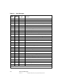
Tables
4.1
4.2
4.3
4.4
4.5
4.6
4.7
4.8
4.9
4.10
4.11
4.12
4.13
4.14
4.15
4.16
4.17
4.18
4.19
4.20
4.21
4.22
4.23
4.24
4.25
4.26
4.27
4.28
4.29
4.30
4.31
4.32
4.33
4.34
4.35
Conventions
Display Adapter Information
Enable or Disable Automatic Rebuild
Set Adapter Properties
Display Specified Adapter Properties
Display Adapter Time
Set Factory Defaults
Bootable Logical Drive ID
Set BIOS Options
Event Log Management
Add RAID 0 or 1 Configuration
Configure Each Disk as RAID 0
Add RAID 10 Configuration
Clear Existing Configuration
Display Existing Configuration
Save Adapter Configuration
Restore Configuration Data from File
Delete Logical Drives
Display Free Space
Display Logical Drive Information
Display Logical Drive Cache Settings
Manage Logical Drive Initialization
Manage Consistency Check
View Ongoing Background Initialization
Display Logical Drive and Physical Disk Drive Information
Display Number of Logical Drives
Display Physical Disk Drive Information
Set Physical Disk Drive State to Online
Set Physical Disk Drive State to Offline
Set Physical Disk Drive State to Unconfigured-Good
Manage Hotspares
Rebuild Physical Disk Drive
Locate Physical Disk Drive and Flash LED
Replace Configured Disk Drives and Start Automatic
Rebuild
Prepare Unconfigured Physical Disk Drives for Removal
4-3
4-5
4-5
4-6
4-6
4-7
4-7
4-7
4-8
4-8
4-9
4-10
4-10
4-10
4-11
4-11
4-11
4-12
4-12
4-12
4-13
4-13
4-14
4-15
4-15
4-15
4-16
4-16
4-16
4-17
4-17
4-18
4-18
4-18
4-19
xv
Version 1.0
Copyright © 2006 by LSI Logic Corporation. All rights reserved.
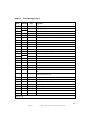
4.36
4.37
4.38
4.39
A.1
A.2
Display Number of Physical Disk Drives
Display List of Physical Drives
Display MegaCLI Version
Display MegaCLI Help
Event Error Levels
Event Messages
xvi
Version 1.0
Copyright © 2006 by LSI Logic Corporation. All rights reserved.
4-19
4-19
4-20
4-20
A-1
A-2
Chapter 1
Overview
This manual explains the features of the Embedded MegaRAID®
Software. It includes instructions for using the MegaRAID BIOS
Configuration Utility, the MegaCLI command line utility, and the
MegaRAID Storage Manager™ software. You can use these three
utilities to create storage configurations on physical disk drives controlled
by Embedded MegaRAID Software. The manual also includes
instructions for installing the Embedded MegaRAID Software drivers in
Microsoft Windows and Linux systems.
This chapter contains the following sections:
1.1
•
Section 1.1, “Embedded MegaRAID Software Features”
•
Section 1.2, “RAID Overview”
Embedded MegaRAID Software Features
The Embedded MegaRAID Software supports up to eight SAS or SATA
ports, depending on the hardware platform. This provides a cost-effective
way to achieve higher transfer rates and reliability.
The following sections list the features of the BIOS, the Ctrl-M
Configuration Utility, the driver, and the disk management features.
1.1.1
BIOS Features
The Embedded MegaRAID Software BIOS has the following features:
•
Support for Interrupt 13 and Enhanced Disk Drive Specification
•
Support for Int19h
•
Option ROM size of 64 Kbyte
Embedded MegaRAID Software User’s Guide
Version 1.0
Copyright © 2006 by LSI Logic Corporation. All rights reserved.
1-1
•
Support for BIOS Boot Specification (BBS) (If available in system
BIOS, this allows the user to select the controller from which to boot.)
•
Support for power-on self test (POST)
•
Support for Post Memory Management (PMM): Specification v1.01,
November 21, 1997
•
Industry-standard EBDA
•
POST and run-time BIOS support for device insertion and removal
•
Support for Stop On Error during boot-up
•
48-bit LBA support for read, write, and flush cache functions
•
Support for drive roaming
•
Support for >2 terabyte physical and logical drives
•
Support for migration path from Embedded MegaRAID Software to
MegaRAID SAS/SATA hardware (this requires support from
hardware RAID)
The following features are supported by the BIOS and the Ctrl-M
Configuration Utility:
1.1.2
•
Automatic resume of rebuilding, Check Consistency, and initialization
•
Global hotspare support based on defined size of the array
•
Soft Bad Block Management (SBBM) support
•
Support for RAID levels 0, 1, and 10
•
Support for auto rebuild
•
Support for up to eight physical drives and eight logical drives
•
Stripe size of 64 Kbytes only
•
Support for Disk Coercion, with options None, 128 Mbytes, 1 Gbyte
Ctrl-M Configuration Utility Features
The Ctrl-M Configuration Utility supports the following features:
1-2
•
Ability to select a logical drive as boot device (by default, logical
drive 0 is the boot drive)
•
Support to disable/enable BIOS boot support
Overview
Version 1.0
Copyright © 2006 by LSI Logic Corporation. All rights reserved.
1.1.3
•
Hot Auto Rebuild (during a hot plug event or when the user forces
the physical drive offline)
•
Hot Plug support (drive insertion and removal)
•
Support for array cache setting (RAID 10 volume is considered as a
single array, though it may have 2, 3, or 4 spans)
•
Support for >2 terabyte logical drives
•
Support for random deletion of logical drives
Driver Features
The Embedded MegaRAID Software driver supports the following
features:
1.1.4
•
RAID levels 0, 1, and 10
•
48-bit LBA
•
Online mirror rebuilding
•
Check Consistency for mirrored disks
•
Soft Bad Block Management (SBBM)
Manageability/Disk Console Features
The following features are available to manage the logical and physical
disks in the system:
•
Configuration information display (in MegaRAID BIOS Configuration
Utility and MegaRAID Storage Manager software)
•
Support for RAID levels 0, 1, and 10
•
Online mirror rebuilding
•
Online consistency checks
•
Array management software
•
Error logging and notification
•
Support for hot device insertion and removal
•
Automatic resume of rebuilding on restart
•
Support for manual rebuild
•
Ability to create up to eight logical drives per configuration
Embedded MegaRAID Software Features
Version 1.0
Copyright © 2006 by LSI Logic Corporation. All rights reserved.
1-3
1.2
•
Auto-configuration support of newly added physical drive
•
Support for global hotspares
•
Support for disk coercion
•
Array initialization support (fast and normal)
•
Logical drive availability immediately after creation
•
Supported stripe size of 64 Kbytes
RAID Overview
This section provides a brief overview of the types of RAID configurations
that Embedded MegaRAID Software supports.
The first step in creating a RAID storage configuration is to configure
physical disk drives in arrays. As defined for Embedded MegaRAID
Software, an array is a group of one to eight physical disks that is seen
by the host computer system as one large disk drive, or logical drive.
Only one RAID level can be assigned to each array.
•
A RAID 0 array consists of one to eight physical drives.
•
A RAID 1 array consists of two physical drives.
•
A RAID 10 array consists of four, six, or eight drives.
Note:
Some hardware configurations do not support eight disk
drives. So depending on the hardware, the actual maximum
number of drives for RAID 0 and RAID 10 arrays can be
fewer than eight.
Important:
LSI recommends that you do not use both SAS and SATA
drives in the same array. Using different drive interfaces in
this way could cause unpredictable behavior, decreased
performance, an increased error count, and decreased
Mean Time Between Failures (MTBF).
You can use either of these two strategies when creating RAID arrays
and logical drives:
•
1-4
Maximize Fault Tolerance: You can maximize fault tolerance to
protect against loss of data by creating a RAID 1 array with mirroring.
Overview
Version 1.0
Copyright © 2006 by LSI Logic Corporation. All rights reserved.
All data is written to the primary disk in the array and is also written
(mirrored) to a second disk.
•
Maximize Logical Drive Performance: You can maximize logical
drive performance by creating a RAID 0 array with striping. Data is
broken into segments and can be simultaneously written to or read
from several different stripes on several different disks in the array.
RAID 10 arrays combine both striping and mirroring to provide high
data transfer rates and data redundancy.
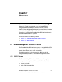
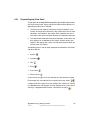
1.2.1
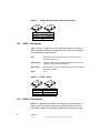
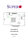
RAID 0 Description
RAID 0 (Figure 1.1) provides disk striping across all disk drives in the
array. RAID 0 does not provide any data redundancy, but does offer the
best performance of any RAID level. RAID 0 breaks up data into smaller
segments, then stripes the data segments across each drive in the array,
as shown in Figure 1.1. The size of each data segment is determined by
the stripe size parameter, which is set during the creation of the RAID
set.
Note:
It is possible to create each disk as a single-drive RAID 0
array. However, spanning across single drive RAID 0 arrays
is not supported.
By breaking up a large file into smaller segments, Embedded MegaRAID
Software can use both SATA ports and drives to read or write the file
faster. This makes RAID 0 ideal for applications that require high
bandwidth but do not require fault tolerance.
Uses
Provides high data throughput, especially for large files; any
environment that does not require fault tolerance
Strong Points
Provides increased data throughput for large files; no capacity
loss penalty for parity
Weak Points
Does not provide fault tolerance; all data lost if any drive fails
Drives
One to eight
RAID Overview
Version 1.0
1-5
Copyright © 2006 by LSI Logic Corporation. All rights reserved.
Figure 1.1
RAID 0 Array Example with Two Disk Drives
Segment 1
Segment 3
Segment 5
Segment 7
1.2.2
Segment 2
Segment 4
Segment 6
Segment 8
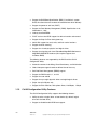
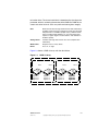
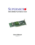
RAID 1 Description
RAID 1 (Figure 1.2) duplicates all data from one drive to a second drive.
RAID 1 provides complete data redundancy, but at the cost of doubling
the required data storage capacity.
Uses
Databases or any other mission critical environment that
requires fault tolerance
Strong Points
Provides complete data redundancy; RAID 1 is ideal for any
application that requires fault tolerance
Weak Points
Requires twice as many hard drives; performance is impaired
during drive rebuilds
Drives
Two
Figure 1.2
RAID 1 Array
Segment 1
Segment 2
Segment 3
Segment 4
1.2.3
Segment 1 Duplicated
Segment 2 Duplicated
Segment 3 Duplicated
Segment 4 Duplicated
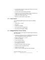
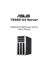
RAID 10 Description
RAID 10, a combination of RAID 1 and RAID 0, has mirrored drives. It
breaks up data into smaller blocks, then stripes the blocks of data to
each RAID 1 RAID set. Each RAID 1 RAID set then duplicates its data
1-6
Overview
Version 1.0
Copyright © 2006 by LSI Logic Corporation. All rights reserved.
to its other drive. The size of each block is determined by the stripe size
parameter, which is set during the creation of the RAID set. RAID 10 can
sustain one drive failure in each array while maintaining data integrity.
Uses
Works best for data storage that must have 100% redundancy
of RAID 1 (mirrored arrays) and that also needs the enhanced
I/O performance of RAID 0 (striped arrays); RAID 10 works
well for medium-sized databases or any environment that
requires a higher degree of fault tolerance and moderate to
medium capacity
Strong Points
Provides both high data transfer rates and complete data
redundancy
Weak Points
Requires twice as many drives
Drives
Four, six, or eight
Figure 1.3 shows a RAID 10 array with four disk drives.
Figure 1.3
RAID 10 Array
RAID 1
Disk 1
Segment 1
Segment 3
Segment 5
RAID 1
Disk 2
Disk 3
Segment 2
Segment 4
Segment 6
Segment 1
Segment 3
Segment 5
Disk 4
Segment 2
Segment 4
Segment 6
RAID 0
RAID Overview
Version 1.0
1-7
Copyright © 2006 by LSI Logic Corporation. All rights reserved.
1-8
Overview
Version 1.0
Copyright © 2006 by LSI Logic Corporation. All rights reserved.
Chapter 2
Driver Installation
This chapter explains how to install the Embedded MegaRAID Software
drivers for the Windows 2000, Windows 2003, Windows XP, Red Hat
Linux, and SuSE Linux operating systems.
Note:
No driver installation is required for DOS. The ROM BIOS
contains the low-level driver that is required for MS-DOS.
The chapter contains the following sections:
2.1
•
Section 2.1, “Windows 2000/2003/XP Driver Installation”
•
Section 2.2, “Linux Driver Installation”
Windows 2000/2003/XP Driver Installation
Perform the following steps to install the Embedded MegaRAID Software
driver for Windows 2000, Windows 2003, or Windows XP.
1. Boot the system with the Windows Boot Installation CD or diskette.
The following message appears:
Setup is inspecting your computers hardware
configuration.
2. When the next prompt appears, press F6 to install the RAID/SCSI
adapter driver.
3. When installation prompts for a key after copying some files, press
S to add the SATA RAID driver.
You are prompted for the floppy diskette that contains the LSI
Embedded MegaRAID Software driver.
4. Insert the Embedded MegaRAID Software driver diskette and press
Enter.
Embedded MegaRAID Software User’s Guide
Version 1.0
Copyright © 2006 by LSI Logic Corporation. All rights reserved.
2-1
5. Scroll down the list and select the appropriate driver for the Windows
version installed on your system, then click OK.
6. Continue with the normal installation procedure.
2.1.1
Updating the Windows 2000/2003/XP Driver
Perform the following steps to update the Embedded MegaRAID
Software driver for Windows 2000/2003/XP or to install this driver on an
existing system booted from a standard IDE drive.
1. Click Start, point to Settings, and then click Control Panel.
2. Double-click System, click the Hardware tab, and then click Device
Manager.
Device Manager starts.
3. In Device Manager, double-click SCSI and RAID Controllers, rightclick the device for which you are installing the driver, and then click
Properties.
4. On the Driver tab, click Update Driver to open the Update Device
Driver wizard, and then follow the wizard instructions to update the
driver.
2.1.2
Confirming the Windows 2000/2003/XP Driver Installation
Perform the following steps to confirm that the Embedded MegaRAID
Software driver for Windows 2000/2003/XP is installed properly.
1. Click Start, point to Settings, and then click Control Panel.
2. Double-click System, click the Hardware tab, and then click Device
Manager.
Device Manager starts.
3. In Device Manager, double-click SCSI and RAID Controllers, rightclick the device for which you are installing the driver, and then click
Properties.
4. On the Driver tab, click Driver Details and verify that the driver
information is correct.
2-2
Driver Installation
Version 1.0
Copyright © 2006 by LSI Logic Corporation. All rights reserved.
2.2
Linux Driver Installation
This section explains how to make fresh installations of the Embedded
MegaRAID Software driver for Red Hat Enterprise Linux 3.0 and 4.0 and
SuSE Linux Enterprise Server 9.
2.2.1
Obtaining the Driver Image File
The Linux driver is offered in the form of a driver update disk. The
required file is dud-[driver version].img, which is the driver
update disk for the Embedded MegaRAID Software stack.
You can obtain the latest driver files from the Download Center on the
LSI web site at: http://www.lsilogic.com.
2.2.2
Preparing the Installation Disk(s) for Linux
This section describes how to prepare the Linux installation disk(s) from
the driver image files, using either the Windows or Linux operating
systems.
2.2.2.1
Preparing Installation Disks with the Windows Operating System
Under Windows, you can use the rawrite floppy image writer utility to
create disk images from image files. The image writer can be
downloaded from the Internet. Perform the following steps to build
installation diskettes.
1. Copy the driver update disk image dud-[driver version].img
and the file rawrite.exe to a directory.
2. Confirm that the files are in the selected directory.
3. If necessary, use this command to change the filename of the driver
update disk to a name with fewer than eight characters:
copy dud-[driver version].img dud.img.
4. Open the DOS Command Prompt and navigate to the directory
where rawrite.exe is located.
5. Type the following command to create the installation diskette:
rawrite
Linux Driver Installation
Version 1.0
Copyright © 2006 by LSI Logic Corporation. All rights reserved.
2-3
Then press Enter.
You are prompted to enter the name of the boot image file.
6. Type the following:
dud.img
Press Enter.
You are prompted for the target drive diskette.
7. Insert a floppy diskette into the floppy drive and type:
A:
Then press Enter.
8. Press Enter again to start copying the file to the diskette.
9. After the command prompt returns and the floppy disk drive LED
goes out, remove the diskette.
10. Label the diskette with the image name.
2.2.2.2
Preparing Installation Disks with the Linux Operating System
Under Red Hat Linux and SuSE Linux, you can use a driver diskette
utility to create disk images from image files. Perform the following steps
to create the driver update disk:
1. Copy the driver update disk image dud-[driver version].img
to a Linux system.
2. Insert a blank floppy diskette into the floppy drive.
3. Confirm that the files are in the selected directory.
4. Create the driver update diskette using the following command:
dd if=dud-[driver version].img of=/dev/fd0
5. After the command prompt returns and the floppy disk drive LED
goes out, remove the diskette.
6. Label the diskette with the image name.
2-4
Driver Installation
Version 1.0
Copyright © 2006 by LSI Logic Corporation. All rights reserved.
2.2.3
Installing the Red Hat Linux Driver on a New System
This section describes the fresh installation of the Red Hat Enterprise
Linux 3.0 or 4.0 device driver on systems with the Embedded MegaRAID
Software stack. After you prepare the installation disks with the driver
image, perform the following steps to install the driver on a new system.
1. Boot to CD-ROM (Disk 1).
The Red Hat introductory screen appears.
2. Type the following at the boot prompt:
linux dd
3. Press Enter.
The prompt asks whether you have a driver disk.
4. Use the arrow key to select Yes, then press Enter.
5. Select fd0 to indicate you have a floppy diskette with the driver on it.
6. Insert the floppy diskette in the A:/ drive and press Enter.
The installer locates and loads the driver for your device. The
following message appears:
Loading megaswr driver...
The prompt at the next screen asks whether you have another driver.
7. Follow the Red Hat Linux installation procedure to complete the
installation.
8. Reboot the system.
2.2.4
Updating the Red Hat Linux Driver (Generic)
Perform the following steps to update the Red Hat Linux driver or to
install the Red Hat Linux driver in an existing system booted from a
standard SAS/SATA drive or systems with the Embedded Software RAID
stack.
1. Create a RAID array on the controller using the Embedded SATA
RAID Setup Utility.
2. Boot the system with the Red Hat Linux Installation CD from the
primary controller or disk.
The Red Hat introductory screen appears.
Linux Driver Installation
Version 1.0
Copyright © 2006 by LSI Logic Corporation. All rights reserved.
2-5
3. Mount the driver update diskette (DUD) using the following
command:
#mount /dev/fd0 /mnt/floppy
4. Unzip the modules.cgz file that is on the DUD to get driver images
for different Red Hat operating systems:
#mkdir -p /home/megasr
#cd /home/megasr
#cp /mnt/floppy/modules.cgz .
#gunizip -S .cgz modules.cgz
This generates a new file named modules:
#cpio -ivd < modules
This provides the following driver images:
{<kernel version>,<kernel version>smp,
<kernel version>BOOT }/megasr.o
5. Update the Megasr driver module for the required kernels using the
following commands:
#cd /home/megasr
If the /lib/modules/<kernel version>/update/ directory is
present, use the following command:
# cp <kernel version>/megaide.[o/ko]
/lib/modules/<kernel version>/update/megaide.[o/ko]
If the /lib/modules/<kernel version>/update/ directory is
not present, use the following command:
# cp <kernel version>/megaide.[o/ko]
/lib/modules/<kernel version>
/kernel/drivers/scsi/megaide.[o/ko]
6. Create a Megasr driver entry in the configuration file. The Red Hat
configuration file is /etc/modules.conf.
If the Megaide entry is not present in /etc/modules.conf, add the
following line:
alias scsi_hostadapter megasr
If the ata_piix SCSI driver entry (located on the following
paragraph) is present in /etc/modules.conf, remove it. It must be
removed because otherwise the ata_piix driver would take control
2-6
Driver Installation
Version 1.0
Copyright © 2006 by LSI Logic Corporation. All rights reserved.
of the RAID controller without checking the subsystem device or
Vendor ID. The ata_piix SCSI driver entry is the following:
alias scsi_hostadapter ata_piix
7. Create a new initrd image for the required kernel.
Red Hat installation uses the mk_initrd command to create an initrd
image. The following command creates an initrd image for the
<kernel version>smp kernel in the boot directory. See the
mk_initrd man page for more information. The command is:
#mkinitrd /boot/initrd<kernel version>smp.img.new
<kernel version>smp
8. Modify the lilo.conf/grub.conf file by adding newly created
initrd(s) as new entries in the /etc/lilo.conf file.
The suggested method is to copy an existing lilo entry in the file and
paste it as a new one. Then modify its kernel image name, initrd
image name, and label name.
Sample Lilo Entry
image=/boot/vmlinux-<kernel version>smp label=linuxnew
initrd=/boot/initrd-<kernel version>smp.img.new
read-only appended=root=LABEL=/ ”
Sample Grub Entry
title Red Hat Linux (<kernel version> with Megaide
driver)
root (hd0,0)
kernel /vmlinuz-<kernel version> ro root=LABEL=/
initrd /initrd-<kernel version>.img.new
9. Update the boot loader. If the boot loader is Lilo, run the lilo
command to update the boot loader. The lilo command is:
#lilo
10. Reboot the system to the new boot loader entry.
Linux Driver Installation
Version 1.0
Copyright © 2006 by LSI Logic Corporation. All rights reserved.
2-7
2.2.5
Installing the SuSE Linux Enterprise Server 9 Driver
This section describes the fresh installation of the SuSE Linux Enterprise
Server 9 driver on a system with the Embedded MegaRAID Software
stack. Prepare installation disks with the driver image, then perform the
following steps to install the driver.
1. Create a RAID array using the MegaRAID BIOS Configuration utility.
(See Chapter 3, “MegaRAID BIOS Configuration Utility.”)
2. Boot the system using the SLES Disk.
3. When the first screen appears, press F6 and select Installation on
the menu.
You are prompted for the diskette.
4. Insert the driver update diskette in the A:/ drive and press Enter.
5. Press OK. The following message appears:
LSI Soft RAID Driver Updates added.
6. At the menu, select the driver update medium and press the Back
button.
7. Continue the installation process and complete it.
2-8
Driver Installation
Version 1.0
Copyright © 2006 by LSI Logic Corporation. All rights reserved.
Chapter 3
MegaRAID BIOS
Configuration Utility
The MegaRAID BIOS Configuration Utility (CU) is used to configure disk
arrays and logical drives and to do other configuration tasks in a pre-boot
environment. This chapter has the following sections:
•
Section 3.1, “Performing a Quick Configuration”
•
Section 3.2, “Configuring Arrays and Logical Drives”
•
Section 3.3, “Setting the Hard Disk Write Cache and Read Ahead
Policies”
•
Section 3.4, “Rebuilding a Drive”
•
Section 3.5, “Hot Plug Support”
•
Section 3.6, “Checking Data Consistency”
•
Section 3.7, “Viewing and Changing Device Properties”
•
Section 3.8, “Forcing Drives Online or Offline”
•
Section 3.9, “Configuring a Bootable Logical Drive”
•
Section 3.10, “Deleting a Logical Drive”
•
Section 3.11, “Clearing a Storage Configuration”
Embedded MegaRAID Software User’s Guide
Version 1.0
Copyright © 2006 by LSI Logic Corporation. All rights reserved.
3-1
3.1
Performing a Quick Configuration
This section provides high level instructions for quickly configuring arrays
and logical drives with the MegaRAID BIOS CU. These instructions are
intended for users that are familiar with configuration utilities and tools.
Refer to Section 3.2, “Configuring Arrays and Logical Drives,” for detailed
configuration instructions. To ensure the best performance, select the
optimal RAID level for the logical drive you create. (For an explanation of
RAID levels, see Chapter 1, “Overview.”)
Important:
LSI recommends that you do not use both SAS and SATA
drives in the same array. Using different drive interfaces in
this way could cause unpredictable behavior, decreased
performance, an increased error count, and decreased
MTBF.
Perform the following steps to configure arrays and logical drives using
the MegaRAID BIOS CU:
1. Boot the system.
2. Start the MegaRAID BIOS CU by pressing Ctrl+M.
3. Select Configure from the Management Menu.
4. Select a configuration method from the Configuration menu (Easy
Configuration, New Configuration, or View/Add Configuration).
5. Create arrays using the available physical drives.
6. Define the logical drive(s) using the space in the arrays.
7. Initialize the new logical drive(s).
3.2
Configuring Arrays and Logical Drives
This section provides detailed instructions for configuring arrays and
logical drives with the MegaRAID BIOS CU. LSI recommends that you
use drives with the same capacity when you create a storage
configuration. If you use drives with different capacities in one array, the
CU limits each drive to the capacity of the smallest drive.
3-2
MegaRAID BIOS Configuration Utility
Version 1.0
Copyright © 2006 by LSI Logic Corporation. All rights reserved.
The number of physical drives in a specific array determines the possible
RAID levels that you can implement with the array.
3.2.1
•
RAID 0 requires from one to eight physical drives.
•
RAID 1 requires two physical drives.
•
RAID 10 requires four, six, or eight physical drives.
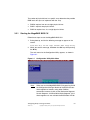
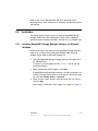
Starting the MegaRAID BIOS CU
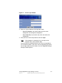
Follow these steps to start the MegaRAID BIOS CU:
1. During boot-up, wait for the following message to appear on the
screen:
Press Ctrl-M to run LSI Logic Software RAID Setup Utility
2. When you see this message, hold down the Ctrl key while pressing
the M key.
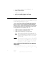
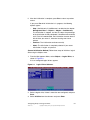
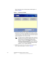
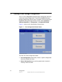
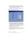
The main menu for the Configuration Utility appears, as shown in
Figure 3.1.
Figure 3.1
Note:
Configuration Utility Main Menu
When you start the MegaRAID BIOS CU by pressing Ctrl-M
the Configuration Manager Module of the BIOS allocates
three segments of memory using either PMM or
conventional memory: these are the Destination Segment,
Scratch Segment, and Read Write Buffer Segment. If the
three segments are not available the BIOS hooks INT19h
Configuring Arrays and Logical Drives
Version 1.0
Copyright © 2006 by LSI Logic Corporation. All rights reserved.
3-3
and loads the CU at the fixed segments 5000:0
(Destination Segment), 6000:0 (Scratch Segment) and
7000:0 (Read Write Buffer Segment) after POST.
3.2.2
Using Easy Configuration
When you select the Easy Configuration option, the CU creates one or
more arrays from the available physical drives and configures each array
as a single logical drive. If logical drives have already been configured,
the CU does not change their configuration. Follow these steps to create
a logical drive using Easy Configuration:
1. Select Configuration→ Easy Configuration from the Management
Menu. A list of available (READY) physical drives appears.
2. Use the arrow keys to select the physical drives to include in the
array.
3. Press the spacebar to add each selected physical drive to the new
array.
When you select a physical drive, its status changes from READY to
ONLIN A[array number]-[drive number]. For example,
ONLIN A00-01 means array 0, disk drive 1.
4. To create a global hotspare drive, highlight a READY disk drive and
press F4. Then select Yes from the pop-up menu.
5. To define multiple arrays, select all the drives you want for the first
array, then press Enter to start selecting drives for the second array,
and so on.
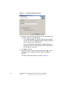
6. When you have selected drives for all desired arrays, press F10.
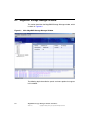
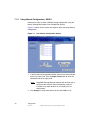
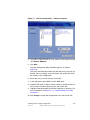
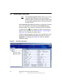
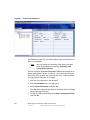
7. Press the spacebar to select an array.
The Logical Drive Configuration screen appears, as shown in
Figure 3.2. This screen shows the logical drive number, RAID level,
logical drive size, number of stripes in the physical array, stripe size,
and state of the logical drive.
3-4
MegaRAID BIOS Configuration Utility
Version 1.0
Copyright © 2006 by LSI Logic Corporation. All rights reserved.
Figure 3.2
Logical Drive Configuration Screen
8. Highlight RAID and press Enter.
The available RAID levels for the current logical drive are displayed.
9. Select a RAID level for the logical drive and press Enter.
10. (Optional) Change the drive’s default Write Cache and Read Ahead
policies (see Section 3.3, “Setting the Hard Disk Write Cache and
Read Ahead Policies”).
11. When you have finished defining the current logical drive, select
Accept and press Enter.
12. Save the configuration when prompted, and press any key to return
to the Management Menu.
13. Initialize the new logical drive(s). (See Section 3.2.5, “Initializing
Logical Drives,” for detailed instructions.)
3.2.3
Using New Configuration and View/Add Configuration
When you select the New Configuration menu option, the CU deletes the
existing arrays and logical drives and replaces them with the new
configuration that you specify. The View/Add Configuration menu option
lets you view the existing configuration or add to the existing
configuration, if possible.
Caution:
If you want to keep the existing data on the storage
configuration, use View/Add Configuration instead of New
Configuration.
Configuring Arrays and Logical Drives
Version 1.0
Copyright © 2006 by LSI Logic Corporation. All rights reserved.
3-5
Follow these steps to configure a disk array using the New Configuration
or View/Add Configuration option:
1. Select Configuration→ New Configuration or Configuration→
View/Add Configuration from the Management Menu. If you
selected New Configuration, select Yes to proceed. (This confirms
that you are erasing the existing storage configuration.)
The CU displays an array selection window.
Note:
The existing storage configuration will be erased only if you
save the newly created configuration at the end of the
process. It you do not save the new configuration, the CU
will restore the previously existing configuration.
2. Use the arrow keys to select physical drives for the new array.
3. Press the spacebar to add each selected physical drive to the new
array.
When you select a drive, its status changes from READY to ONLIN
A[array number]-[drive number]. For example, ONLIN
A00-01 means array 0, disk drive 1.
4. To create a global hotspare drive, highlight a READY disk drive and
press F4. Then select Yes from the pop-up menu.
Make sure the capacity of the hotspare drive is equal to or larger
than the capacity of the disks in the array and that it is the same type
of drive (SAS or SATA).
Note:
The hotspare drive will rebuild a failed drive even if it is SAS
and the failed drive is SATA, or vice versa. Once the rebuilt
is completed, however, LSI recommends that you replace
the new array member with a drive of the same type.
5. To define multiple arrays, select all the drives you want for the first
array, then press Enter to start selecting drives for the second array,
and so on.
6. When you have selected drives for all desired arrays, press F10.
7. Press the spacebar to select an array, if needed.
8. Highlight RAID and press Enter.
A list of the available RAID levels for the current logical drive
appears.
3-6
MegaRAID BIOS Configuration Utility
Version 1.0
Copyright © 2006 by LSI Logic Corporation. All rights reserved.
9. Select a RAID level for the logical drive and press Enter.
10. (Optional) Set the logical drive size by highlighting Size and pressing
Enter.
The minimum valid logical drive size is 64 Mbytes. An error message
will appear if you try to create a logical drive that is smaller than
64 Mbytes. By default, all the available space in the array is assigned
to the current logical drive. For RAID 10 arrays, only one logical drive
can be defined for the entire array.
11. (Optional) Change the disks’s default Write Cache and Read Ahead
policies (see Section 3.3, “Setting the Hard Disk Write Cache and
Read Ahead Policies”).
12. When you have finished defining the current logical drive, select
Accept and press Enter.
13. Configure additional logical drives on the same array, if desired. If
you have created more than one array, configure a logical drive on
the second array.
14. Save the configuration when prompted, and press any key to return
to the Management Menu.
15. Initialize the new logical drive(s). (See Section 3.2.5, “Initializing
Logical Drives,” for detailed instructions.)
3.2.4
Creating a Global Hotspare Drive
The MegaRAID BIOS CU enables you to create global hotspare drives
(dedicated hotspare drives are not supported). A hotspare drive can
automatically replace a failed drive in a redundant RAID 1 or RAID 10
array, to protect against data loss.
Important:
When you select disk drive for a global hotspare, be sure it
is the same type of drive (either SAS or SATA) as the drives
in the arrays that it will protect. LSI recommends that you
do not combine SAS and SATA drives in the same array.
You can create a hotspare when you are configuring a new storage
configuration, as described in the previous sections. To add a hotspare
drive to an existing redundant storage configuration, follow these steps:
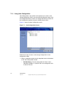
1. Select Objects from the Management Menu.
2. Select Physical Drive. A list of physical drives appears.
Configuring Arrays and Logical Drives
Version 1.0
Copyright © 2006 by LSI Logic Corporation. All rights reserved.
3-7
3. Select an unconfigured drive or Ready drive from the list, and press
Enter.
4. When the Physical Drive Property menu appears, select Make Hot
Spare and press Enter.
5. Select Yes from the pop-up menu to create the hotspare drive.
Note:
3.2.5
To remove a hotspare drive, perform steps 1 and 2 above,
select the HOTSP disk, press Enter, select Force Offline,
and press Enter. The status of the drive changes to
READY, and it can then be used in another new array.
Initializing Logical Drives
Caution:
When you initialize a logical drive all existing data on the
logical drive is erased.
This section explains the two methods of initializing a logical drive with
the MegaRAID BIOS CU. If the Fast Init property is enabled, fast
initialization will be used. In fast initialization, the MegaRAID BIOS CU
quickly writes zeroes to the first and last 8 Mbyte regions of the new
logical drive. If the Fast Init property is not enabled, the MegaRAID BIOS
CU performs a complete initialization on the logical drive. This may take
a long time if the physical disk drives are large.
(First Initialization Method) Follow these steps to initialize a logical
drive using the Initialize menu.
1. On the Management Menu, select Initialize.
2. Use the spacebar to highlight the logical drive to initialize.
The logical drive name is highlighted in yellow. To deselect it,
highlight the logical drive and press the spacebar again.
3. Press F10.
4. Select Yes at the prompt and press Enter to begin the initialization.
A graph shows the progress of the initialization until it is complete.
3-8
MegaRAID BIOS Configuration Utility
Version 1.0
Copyright © 2006 by LSI Logic Corporation. All rights reserved.
5. After the initialization is complete, press Esc to return to previous
menus.
If you press Esc while initialization is in progress, the following
options appear:
–
Stop: (Available only if AutoResume is enabled on the adapter:
Management Menu→ Objects→ Adapter→ AutoResume.)
The initialization is stopped, and the CU stores the percentage
of the initialization already completed. If AutoResume is enabled,
and if Fast Init is not enabled, the initialization resumes where it
left off when you restart it, instead of starting over from 0
percent.
–
Continue: The initialization continues normally.
–
Abort: The initialization is completely aborted. If you restart
initialization, it begins at 0 percent.
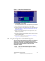
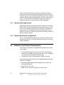
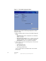
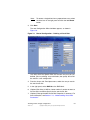
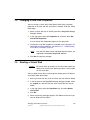
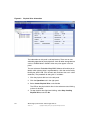
(Second Initialization Method) Follow these steps to initialize a logical
drive using the Objects menu.
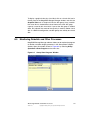
1. From the Management Menu, select Objects→ Logical Drive, as
shown in Figure 3.3.
A list of configured logical drives appears.
Figure 3.3
Logical Drive Submenu
2. Select a logical drive, if there is more than one configured, and press
Enter.
3. Select Initialize from the submenu and press Enter.
Configuring Arrays and Logical Drives
Version 1.0
Copyright © 2006 by LSI Logic Corporation. All rights reserved.
3-9
4. Select Yes at the prompt and press Enter.
The CU displays a bar graph showing the initialization progress.
5. When initialization completes, press Esc to return to the previous
menu.
If you press Esc while initialization is in progress, the Stop, Continue,
and Abort options are available, as explained earlier in this section.
3.3
Setting the Hard Disk Write Cache and Read Ahead
Policies
You can use the MegaRAID BIOS CU to set the hard disk drive Write
Cache and Read Ahead settings. Any read or write cache policy changes
apply to all logical drives on an array. In other words, if two logical drives
are defined on a single array and you change the Read Ahead setting
on one logical drive, the change will also apply to the other logical drive
on the array.
The Disk Write Cache and Read Ahead policies can be set to On or Off.
•
When the disk Write Cache is On, a write transaction is considered
to be complete when all the data has been written to the disk cache.
When disk Write Cache is Off, the write transaction is complete only
when the data has been written to the disk.
•
When disk Read Ahead is On, extra data is read sequentially ahead
of the data that is actually requested and is stored in a cache. If the
additional read-ahead data is then requested, it can be read faster
from the cache than from the disk directly.
Note:
When the disk Write Cache is On, there is a danger that
data could be lost if the power fails before the cached data
is written to disk.
Follow these steps to view or change the logical drive Write Cache or
Read Ahead settings:
1. From the Management Menu, select Objects→ Logical Drive→
Logical Drive n→ View/Update Parameters.
2. Use the arrow key to move the cursor to Disk WC or Read Ahead
and press Enter.
3-10
MegaRAID BIOS Configuration Utility
Version 1.0
Copyright © 2006 by LSI Logic Corporation. All rights reserved.
3. Use the arrow key to select Off or On for Disk WC (DWC) or Read
Ahead.
4. When you see the prompt Change DWC or Change Read Ahead, use
the arrow key to select Off or On, then press Enter to change the
cache setting.
The settings are changed for all logical drives defined on the array.
3.4
Rebuilding a Drive
The MegaRAID BIOS CU enables you to rebuild a drive of a redundant
array if the array has a failed drive. If the failed drive is still good (that is,
if the drive is physically present and its size is greater than or equal to
the defined size of the array) it will be rebuilt. If the drive is small, an error
message will appear and the MegaRAID BIOS CU will not allow the drive
to be rebuilt. A rebuild cannot be started on a failed drive if its size is
even 1 byte smaller than the defined size of the array.
Follow these steps to rebuild a drive:
1. Select Rebuild from the Management Menu.
2. When the list of drives appears, highlight the FAIL drive that you want
to rebuild and press the Spacebar to select it.
3. After selecting the physical drive, press F10 and select Yes at the
confirmation prompt.
The rebuild process begins, and a graph shows the progress of the
rebuild until it is complete. Although the CU changes the disk drive
state to Rebuild at this point, the change does not appear on the
screen while the rebuild is in progress. If the CU detects a media
error on the source drive during rebuild, it initiates a sector read for
that block. If the sector read fails, the CU adds entries to the Soft
Bad Block Management (SBBM) table, writes this table to the target
drive, and displays an error message. Additional error messages are
displayed if the SBBM table is 80% full or 100% full. If the SBBM
table is completely full, the rebuild operation is aborted, and the drive
is marked as FAIL.
Rebuilding a Drive
Version 1.0
3-11
Copyright © 2006 by LSI Logic Corporation. All rights reserved.
4. When rebuild is complete, the CU displays the message:
Rebuilding of Drive X Completed Successfully. Press Esc.
(X = the ID of the rebuilt drive.)
5. Press Esc to display the Management Menu.
The state of the rebuilt disk drive changes from FAIL to ONLIN.
If you press Esc while the rebuild is running, the following options
display:
•
Stop: (Available only if AutoResume is enabled on the adapter:
Management Menu -> Objects -> Adapter -> AutoResume.)
The rebuild is stopped, and the CU stores the percentage of the
rebuild already completed. If AutoResume is enabled, the rebuild
resumes where it left off when you restart it, instead of starting over
from 0 percent.
3.5
•
Continue: The rebuild continues normally.
•
Abort: The rebuild is completely aborted and the disk drive remains
in the FAIL state. If you restart the rebuild, it begins at 0 percent.
Hot Plug Support
The MegaRAID BIOS CU supports hot plugging of disk drives. The
following hot plug message will appear when you insert or remove a disk
drive: A Drive Has Been Inserted/Removed. Configuration
Updated. Press ESC... After you press Esc the inserted or removed
drive will be reflected in the list of drives that appears in the configuration
utility.
Obviously, you should not insert or remove a drive while you are defining
a new logical drive or while an initialization or other process is running.
The following bullets describe how the CU handles hot plugging when
various actions occur:
•
3-12
If the Physical Drive window or one of the Configuration windows is
open when you insert or remove a drive, the window will close when
the hot plug message appears.
MegaRAID BIOS Configuration Utility
Version 1.0
Copyright © 2006 by LSI Logic Corporation. All rights reserved.
3.6
•
CU menus such as Select Boot Drive, Select Adapter, and Logical
Drive menus will completely or partially close when a drive is
inserted or removed.
•
If a Rebuild is in progress when you insert or remove a drive, the CU
will first display the message Rebuilding Of Drive Not Complete!
Press Esc.. followed by the hot plug message. If the Rebuild was
not affected by this hot plug event, it will continue to rebuild from
where it left off, provided that Auto Resume is enabled; otherwise,
Rebuild will start over from the beginning. If the rebuilding array was
affected by the hot plug event, the Rebuild will abort and the array
status will change based on the hot plug operation.
•
If an Initialization is in progress when you insert or remove a drive,
the CU will display the message Initialization of Array Not
Complete! Press ESC.. followed by the hot plug message.
•
If a consistency check is in progress when you insert or remove a
drive, the CU will display the message CC Not Completed! Press
ESC.. followed by the hot plug message.
Checking Data Consistency
The Check Consistency feature can be used on RAID 1 or RAID 10
logical drives to verify the data consistency between the mirrored
physical drives. The MegaRAID BIOS CU automatically corrects any
differences found in the data when a consistency check is run.
Follow these steps to check consistency:
1. On the Management Menu select Check Consistency and press
Enter.
A list of configured logical drives is displayed.
2. Highlight a logical drive with the arrow keys.
3. Press the spacebar to select the logical drive to check for
consistency.
Note:
If you select a RAID 0 logical drive, a message appears
stating that a Check Consistency cannot be performed. To
continue, deselect the logical drive, highlight a redundant
logical drive, and press the spacebar again.
Checking Data Consistency
Version 1.0
Copyright © 2006 by LSI Logic Corporation. All rights reserved.
3-13
4. Press F10.
5. At the prompt, select Yes to start the Check Consistency process
and press Enter. A graph shows the progress of the Check
Consistency operation until it is complete.
If the MegaRAID BIOS CU finds any data inconsistencies while
comparing the source and target drives, it fixes the inconsistency by
writing the source data to the target drive. When this happens, the
following message appears at the bottom of the screen:
The Data on the Drives is inconsistent. Repair done!
If the MegaRAID BIOS CU finds a media error on the source drive,
it pops up a dialog box with this message:
Error in Reading Sectors! Proceed Anyway (Y/N)?
If you press Y, the program skips the bad block and continues. If you
press N, the program aborts the consistency check. The same
message appears if the program finds a hard media error on the
target drive.
If you press Esc while a Check Consistency is running, the following
options are displayed:
3.7
•
Stop: (Available only if AutoResume is enabled on the adapter:
Management Menu→ Objects→ Adapter→ AutoResume.) The
Check Consistency is stopped, and the CU stores the percentage of
the task already completed. If AutoResume is enabled, the Check
Consistency resumes where it left off when you restart it, instead of
starting over from 0 percent.
•
Continue: The Check Consistency continues normally.
•
Abort: The Check Consistency is completely aborted. If you restart
it, it begins at 0 percent.
Viewing and Changing Device Properties
The MegaRAID BIOS CU allows you to view properties for adapters,
logical drives, and physical drives. You can also change some properties
for adapters and logical drives.
3-14
MegaRAID BIOS Configuration Utility
Version 1.0
Copyright © 2006 by LSI Logic Corporation. All rights reserved.
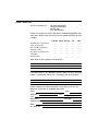
3.7.1
Viewing and Changing Adapter Properties
To view or change adapter properties, follow these steps:
1. On the Management Menu, select Objects→ Adapter.
2. Select an adapter from the list. The following list of adapter
properties appears:
Property
Options
Default
Rebuild Rate
0 to 100 (% of system resources)
30
Chk Const Rate
0 to 100 (% of system resources)
30
FGI Rate (Foreground
initialization rate)
0 to 100 (% of system resources)
30
BGI Rate (Background 0 to 100 (% of system resources)
initialization rate)
30
Disk WC (Disk Write
Cache)
Off (Write
Through
enabled)
Off, On
Read Ahead
On, Off
On
BIOS State
Enable, Disable
Enable
Stop On Error
No, Yes
No
Fast Init
Enable, Disable
Enable
Auto Rebuild
On, Off
On
Auto Resume
Enable
Enable, Disable
When Enabled, you can stop a
consistency check, rebuild, or
initialization and resume it later where it
left off, instead of aborting it and starting
over.
Disk Coercion1
None, 128MB, 1GB
1GB
1. The Disk Coercion property can be accessed only when no configuration is
present for the adapter. Otherwise, an error message will appear.
3. If you want to change the value of a property, highlight it and press
Enter.
4. Select or type a different value for the property and press Enter.
5. When you are finished, press Esc until you return to the
Management Menu.
Viewing and Changing Device Properties
Version 1.0
Copyright © 2006 by LSI Logic Corporation. All rights reserved.
3-15
3.7.2
Viewing and Changing Logical Drive Properties
To view or change logical drive properties, follow these steps:
1. On the Management Menu, select Objects → Logical Drive.
2. Select View/Update Parameters.
The only logical drive properties you can change are Disk WC (Disk
Write Cache) and Read Ahead (see Section 3.3, “Setting the Hard
Disk Write Cache and Read Ahead Policies”). The other properties
are view-only.
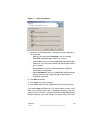
3.7.3
Viewing Physical Drive Properties
To view physical drive properties, follow these steps:
1. On the Management Menu, select Objects → Physical Drive.
2. Highlight a physical drive on the list that appears and press Enter.
3. Select Drive Properties from the menu.
The drive properties are Device Type (Disk), Capacity, Product ID,
and Revision No. These properties are view-only.
3.8
Forcing Drives Online or Offline
The MegaRAID BIOS CU enables you to force drives online or offline.
You may want to force a drive of a redundant array offline so that a
hotspare drive will automatically replace it. An auto rebuild will begin
immediately if the MegaRAID BIOS CU finds a valid hotspare drive to
replace the offline drive.
You may need to force a drive online if it has gone offline due to a power
failure. The MegaRAID BIOS CU will not allow a drive to be forced online
if its size is smaller than the defined size of the array.
To force a drive online or offline, follow these steps:
1. On the Management Menu, select Objects → Physical Drive.
2. Highlight a physical drive that is a member of an array and press
Enter.
3-16
MegaRAID BIOS Configuration Utility
Version 1.0
Copyright © 2006 by LSI Logic Corporation. All rights reserved.
3. Select Force Offline or Force Online from the menu.
If the drive was online, its status changes to FAIL. If it was offline, its
status changes to ONLIN.
3.9
Configuring a Bootable Logical Drive
The default boot logical drive is LD 0. If you change the boot drive to
another logical drive, the BIOS and the CU will preserve this change.
However, if you delete the new boot logical drive, you must be sure to
configure another logical drive for booting. The MegaRAID BIOS CU will
not automatically select a different boot logical drive.
Follow these steps to configure a bootable logical drive:
1. On the Management Menu, select Configure -> Select Boot Drive.
2. Select a logical drive from the list to be the designated boot drive.
3.10 Deleting a Logical Drive
Caution:
Before you delete a logical drive, be sure to back up all the
data you want to keep.
The MegaRAID BIOS CU allows you to delete any single logical drive
defined in the configuration (sometimes referred to as random deletion).
To delete a specified logical drive, follow these steps:
1. Select Objects -> Logical Drive.
2. Highlight the logical drive that you want to delete and press Delete.
3. Select Yes when the confirmation message appears.
3.11 Clearing a Storage Configuration
Caution:
Before you clear a storage configuration, be sure to back
up all the data you want to keep.
Configuring a Bootable Logical Drive
Version 1.0
Copyright © 2006 by LSI Logic Corporation. All rights reserved.
3-17
To clear a storage configuration, follow these steps:
1. On the Management Menu, select Configure → Clear
Configuration.
2. When the message appears, select Yes to confirm.
All logical drives are deleted from the configuration.
3-18
MegaRAID BIOS Configuration Utility
Version 1.0
Copyright © 2006 by LSI Logic Corporation. All rights reserved.
Chapter 4
MegaCLI Command
Tool
The MegaCLI Command Tool (CT) is a command line interface
application that you can use to configure and maintain storage
configurations created with Embedded MegaRAID Software.
Note:
The MegaCLI CT runs in the Microsoft Windows and Linux
environments. The MegaDCLI CT, which supports a subset
of the full command set, runs under DOS only.
This chapter has the following sections:
•
Section 4.1, “MegaCLI CT Overview”
•
Section 4.2, “Exception Handling”
•
Section 4.3, “Command Line Abbreviations and Conventions”
•
Section 4.4, “Adapter Commands”
•
Section 4.5, “BIOS Commands”
•
Section 4.6, “Event Log Commands”
•
Section 4.7, “Configuration Commands”
•
Section 4.8, “Logical Drive Commands”
•
Section 4.9, “Physical Drive Commands”
•
Section 4.10, “Miscellaneous Commands”
Embedded MegaRAID Software User’s Guide
Version 1.0
Copyright © 2006 by LSI Logic Corporation. All rights reserved.
4-1
4.1
MegaCLI CT Overview
MegaCLI CT and MegaDCLI CT are command line interface applications
you can use to configure and manage storage configurations under
Embedded MegaRAID Software. You can use these command tools to
perform the following tasks:
4.2
•
Configure logical drives and create configurations on the adapter
•
Display the configuration on the adapter
•
Display and change logical drive’s properties on the adapter
•
Display and change physical drive’s properties on the adapter
•
Display and change adapter properties
•
Load a configuration to the adapter from a file
•
Save an adapter configuration to a file
•
Start or stop rebuild, consistency check, and initialization
•
Suspend and display an ongoing background initialization
•
Display relevant user messages on the console or write them to the
log file
•
Work in silent mode, if selected (no messages are displayed on the
console)
•
Display adapter inventory data in a single command
•
Customize output strings
•
Exit with predefined success or failure exit codes
•
Set some predefined environment variables, such as number of
adapters and number of logical drives after the execution of CT
•
Display help on how to use the command line options of CT
Exception Handling
MegaCLI CT exits with exit code 0 for all successful operations. In case
of failure, it exits with exit code 1 to 255, depending on the failure
conditions. For example, assume that a rebuild is started on three
physical drives. MegaCLI CT successfully starts rebuilding the first drive
4-2
MegaCLI Command Tool
Version 1.0
Copyright © 2006 by LSI Logic Corporation. All rights reserved.
but fails to start rebuilding the second drive. If this happens, MegaCLI CT
will not attempt to start rebuilding the third drive; instead, it will exit with
an error exit code. In this case, the error code will be
EXIT_ERR_START_RBLD. So even if the command was partially
successful, an error code is still generated.
Some operations such as GetNumberOfAdapters or
GetNumberofLogicaldrives return with the actual number of adapters
or logical drives. These return values are special cases and do not reflect
any error conditions based on the return code, which in these cases
contains meaningful values.
4.3
Command Line Abbreviations and Conventions
Some commands let you specify multiple values. You can enter
commands for a single adapter (-aN), multiple selected adapters
(-a0,1,2) or all adapters (-aALL). This is denoted as -aN|
-a0,1,2|-aALL in the command line syntax used in this chapter.
Table 4.1 lists all of the conventions used in the command line options.
Table 4.1
Conventions
Convention
Description
|
Specifies “or,” meaning you can choose between options.
-aN
N specifies the adapter number for the command.
-a0,1,2
Specifies the command is for adapters 0, 1, and 2. You can
select two or more adapters in this manner.
-aALL
Specifies the command is for all adapters.
-Lx
x specifies the logical drive number for the command.
-L0,1,2
Specifies the command is for logical drives 0, 1, and 2. You can
select two or more logical drives in this manner.
-Lall
Specifies the command is for all logical drives.
{ }
Indicates that the parameter is optional.
You can specify the -Silent command line option for all possible
functions of the MegaCLI CT. If you enter this option at the command
line, no messages are displayed on the screen.
Command Line Abbreviations and Conventions
Version 1.0
Copyright © 2006 by LSI Logic Corporation. All rights reserved.
4-3
Some MegaCLI CT commands that are supported in hardware RAID
configurations are not supported under Embedded MegaRAID Software.
These include the following:
•
Adapter Cache Flush (-AdpCacheFlush)
•
Set Adapter Properties: Only the RebuildRate, BgiRate, CCRate, and
CoercionMode properties are supported
•
Get Adapter Properties: Only the RebuildRate, BgiRate, CCRate,
and CoercionMode properties are supported
•
Cluster Enable is not supported
•
Set Adapter Time (-AdpSetTime)
•
Patrol Read (-AdpPR, -AdpPRSetDelay)
•
Battery Backup commands (-AdpBbuCmd)
•
Set BBU Terminal Logging (-FWTermLog)
•
Foreign configuration (-CfgForeign)
•
Logical Drive Reconstruction (-LDRecon)
•
Set Logical Drive Properties (-LDSetProp)
•
Display Enclosure Information (-EncInfo)
•
Mark Configured Physical Disk Drive as Missing (-PDMarkMissing)
•
Display List of Missing Physical Disk Drives (-PDGetMissing)
•
Flashing the firmware (-AdpFWFlash, -AdpM0Flash)
•
Diagnostics (-AdpDiag, -AdpBatTest, -AdpNVRAM)
The following sections describe the MegaCLI CT commands.
4-4
Note:
Software RAID does not support Write Policy, Read Policy,
or I/O Policy. Software RAID only support enabling and
disabling the hard disk drive’s write cache and read-ahead
functions.
Note:
MegaCLI CT for Embedded MegaRAID Software does not
support the concept of disk enclosures, except for a default
Enclosure 0 (E0). Some of the commands support an
E0:Sn syntax that enables you to specify a disk drive in a
particular “slot” in this default enclosure.
MegaCLI Command Tool
Version 1.0
Copyright © 2006 by LSI Logic Corporation. All rights reserved.
4.4
Adapter Commands
You can use the commands in this section to set or display properties
related to the adapter(s).
Note:
4.4.1
The Embedded MegaRAID Software drivers function as
virtual “adapters” or “controllers.” Because the drivers are
not actual hardware components, some of the adapter
parameters do not apply to them.
Display Adapter Information
Use the command in Table 4.2 to display information on adapter
parameters such as the number of logical drives and initiator ID.
Table 4.2
Display Adapter Information
Syntax
CmdTool –AdpAllInfo -aN|-a0,1,2|-aALL
Description
Displays parameters on the selected adapter(s). Displayed information includes
initiator ID, current status of auto rebuild, alarm, number of logical drives, rebuild rate,
bus number/device number, present RAM, SAS settings, serial number of the board,
and SAS address.
MegaCLI CT does not support display of the firmware version or BIOS version, as
the driver does not support it.
4.4.2
Enable or Disable Automatic Rebuild
Use the command in Table 4.3 to turn automatic rebuild on or off for the
selected adapter(s). If you have configured hotspares and enabled
automatic rebuild, the RAID adapter automatically tries to use them to
rebuild failed disks. Automatic rebuild also controls whether a rebuild will
start when a drive that was part of the array is reinserted.
Table 4.3
Enable or Disable Automatic Rebuild
Syntax
CmdTool –AdpAutoRbld -Enbl|-Dsbl|-Dsply -aN|-a0,1,2|-aALL
Description
Enables or disables automatic rebuild on the selected adapter(s).
The -Dsply option shows the status of the automatic rebuild state.
Adapter Commands
Version 1.0
Copyright © 2006 by LSI Logic Corporation. All rights reserved.
4-5
4.4.3
Set Adapter Properties
This command sets the properties on the selected adapter(s). For
example, for {RebuildRate -val}, you can enter a value between 0
percent and 100 percent. (The rebuild rate is the percentage of the
compute cycles dedicated to rebuilding failed drives.) At 0 percent, the
rebuild is done only if the system is not doing anything else. At 100
percent, the rebuild has a higher priority than any other system activity.
The default rebuild rate of 30 percent is recommended.
Use the command in Table 4.4 to display or set adapter properties.
Table 4.4
Set Adapter Properties
Syntax
CmdTool –AdpSetProp {RebuildRate -val} | {BgiRate –val}|{CCRate –val}|
{CoercionMode –val} -aN|-a0,1,2| -aALL
Description
Sets the properties on the selected adapter(s). The possible settings are:
• RebuildRate: Rebuild rate. Values: 0 to 100.
• BgiRate: Background initilization rate. Values: 0 to 100.
• CCRate: Consistency check rate. Values: 0 to 100.
• CoercionMode: Drive capacity Coercion mode. Values: 0 = None; 1 = 128 Mbytes;
2 = 1 Gbyte. You can set the Coercion mode only when there is no existing
configuration on the adapter.
4.4.4
Display Specified Adapter Properties
Use the command in Table 4.5 to display specified properties on the
selected adapter(s).
Table 4.5
Display Specified Adapter Properties
Syntax
CmdTool –AdpGetProp RebuildRate | BgiRate | CCRate | CoercionMode
-aN|-a0,1,2|-aALL
Description
Displays the properties of the selected adapter(s).
4-6
MegaCLI Command Tool
Version 1.0
Copyright © 2006 by LSI Logic Corporation. All rights reserved.
4.4.5
Display Adapter Time
Use the command in Table 4.5 to display the current time and date of the
selected adapter.
Table 4.6
Display Adapter Time
Syntax
CmdTool –AdpGetTime -aN
Description
Displays the selected adapter’s time in yyyymmdd HH:mm:ss format.
4.4.6
Set Factory Defaults
Use the command in Table 4.7 to set the factory defaults on the selected
adapter(s).
Table 4.7
Set Factory Defaults
Syntax
CmdTool -AdpFacDefSet -aN|-a0,1,2|-aALL
Description
Sets the factory defaults on the selected adapter(s). You cannot set the factory
defaults if the adapter already has a configuration defined on it.
4.5
BIOS Commands
You can use the commands in this section to select the settings for
BIOS-related options.
4.5.1
Set or Display Bootable Logical Drive ID
Use the command in Table 4.8 to set or display the ID of the bootable
logical drive.
Note:
Table 4.8
This option does not write a boot sector to the logical drive.
The operating system will not load if the boot sector is
incorrect.
Bootable Logical Drive ID
Syntax
CmdTool –AdpBootDrive {-Set –LDID} | -Get -aN|-a0,1,2|-aALL
Description
• -Set: Sets the logical drive as bootable so that during the next reboot, the BIOS
will look for a boot sector in the specified logical drive.
• -Get: Displays the bootable logical drive ID.
BIOS Commands
Version 1.0
4-7
Copyright © 2006 by LSI Logic Corporation. All rights reserved.
4.5.2
Set BIOS Options
Use the command in Table 4.9 to set the options for the BIOS status.
Table 4.9
Set BIOS Options
Syntax
CmdTool –AdpBIOS -Enbl|-Dsbl|-Dsply| SOE | BE
Description
Sets BIOS options. The following are the settings you can select on a single adapter,
multiple adapters, or all adapters:
• -Enbl, -Dsbl, -Dsply: Enables, disables or displays the BIOS status on
selected adapter(s).
• -SOE: Stops on BIOS errors during POST for selected adapter(s). When set to
-SOE, the BIOS stops in case of a problem with the configuration. This gives you
the option to enter the configuration utility to resolve the problem. This is available
only when you enable the BIOS status.
• -BE: Bypasses BIOS errors during POST. This is available only when you enable
the BIOS status.
4.6
-aN|-a0,1,2|-aALL
Event Log Commands
Use the command in Table 4.10 to manage the event entries in the event
log for the selected adapter(s).
Table 4.10
Event Log Management
Syntax
CmdTool –AdpEventLog –GetEventlogInfo |{–GetEvents | GetSinceShutdown|
GetSinceReboot | IncludeDeleted | {GetLatest <number>} –f <filename>}
|Clear -aN|-a0,1,2|-aALL
Description
The RAID adapter maintains a volatile circular list of 100 events, which is deleted at
reboot. The following command options are available:
• -GetEventlogInfo: Displays overall event information such as total number of
events, newest sequence number, oldest sequence number, shutdown sequence
number, reboot sequence number, and clear sequence number.
• -GetEvents: Gets event log entry details. The information shown consists of the
total number of entries available at the firmware side since the last clear and
details of each error log entry. Start_entry specifies the initial event log entry
when displaying the log.
• -GetSinceShutdown: Displays all the events since last adapter shutdown.
• -GetSinceReboot: Displays all the events since last adapter reboot.
• -IncludeDeleted: Displays all events, including deleted events.
• -GetLatest: Displays the latest number of events, if it exists. The event data is
written to the file in reverse order.
• -Clear: Clears the event log for the selected adapter(s).
4-8
MegaCLI Command Tool
Version 1.0
Copyright © 2006 by LSI Logic Corporation. All rights reserved.
4.7
Configuration Commands
You can use the commands in this section to create storage
configurations.
4.7.1
Add RAID 0 or 1 Configuration
Use the command in Table 4.11 to add a RAID level 0 or 1 configuration
to the existing configuration on the selected adapter. For RAID level 10,
see Section 4.7.3, “Add RAID 10 Configuration.”
Important:
Table 4.11
LSI recommends that you do not use both SAS and SATA
drives in the same array. Using different drive interfaces in
this way could cause unpredictable behavior, decreased
performance, an increased error count, and decreased
MTBF.
Add RAID 0 or 1 Configuration
Syntax
CmdTool –CfgLDAdd -R0|-R1[E0:Sn] [ -szXXXXXXXX [-szYYYYYYYY [...]]]
[-strpszM] [-Hsp[E5:S5,...]] [–afterLdX] -aN
Description
Adds a RAID level 0 or 1 configuration to a specified adapter. Even if no
configuration is present, you have the option to write the configuration to the adapter.
• –Rx[E0:Sn]: Used to specify RAID level and physical drive enclosure/slot
numbers for an array.
• –strpszM: Used (optionally) to specify a stripe size. (Only 64 Kbyte stripe size is
currently supported.)
• –Hsp[Ex:Sx,…]: Used to create a global hotspare, with physical drive
enclosure/slot numbers specified. This option cannot be used to create dedicated
hotspares.
• –szXXXX: Used to specify the size of a logical drive, where XXXX is a decimal
number of Mbytes. However, the actual size of the logical drive may be smaller,
because the driver requires the number of blocks from physical drives in each
logical drive to be aligned to the stripe size. This option can also be used to create
a configuration on the free space available in the array.
• -AfterLdX: Used to specify which free slot should be used (optional). By default,
MegaCLI CT uses the first free slot available in the array. This option has no
meaning if the array is not already used for configuration.
Configuration Commands
Version 1.0
Copyright © 2006 by LSI Logic Corporation. All rights reserved.
4-9
4.7.2
Configure Each Disk as RAID 0
Use the command in Table 4.12 to configure each physical disk in
Unconfigured-Good state as RAID 0.
Note:
Table 4.12
The MegaCLI CT does not support spanning across these
single-drive RAID 0 configurations.
Configure Each Disk as RAID 0
Syntax
CmdTool –CfgEachDskRAID0 {WT | WB } {NORA | RA | ADRA} {Direct |
Cached} {-strpszM} -aN|-a0,1,2|-aALL
Description
Configures each physical disk in Unconfigured-Good state as RAID 0 on this
controller.
See the preceding command for descriptions of the command line options.
4.7.3
Add RAID 10 Configuration
Use the command in Table 4.13 to add a RAID 10 configuration to the
existing configuration on the selected adapter. For RAID levels 0 or 1,
see Section 4.7.1, “Add RAID 0 or 1 Configuration.”
Table 4.13
Add RAID 10 Configuration
Syntax
CmdTool –CfgSpanAdd -R10 –Array0[E0:Sn] –Array1[E0:Sn] [...] [{WT |
WB}] [{NORA | RA | ADRA}] [{Direct | Cached}] [{-strpszM}] -aN
Description
Creates a RAID level 10 (spanned) configuration from the specified arrays. Even if
no configuration is present, you must use this option to write the configuration to the
adapter.
Multiple arrays are specified using the –ArrayX[E0:Sn,...] option. (Note that X
starts from 0, not 1.) All the arrays must have the same number of physical drives.
At least two arrays must be provided. The options {WT |WB} {NORA | RA | ADRA}
{Direct | Cached} must be entered in the sequence that is shown.
4.7.4
Clear Existing Configuration
Use the command in Table 4.14 to clear the existing storage
configuration on the selected adapter(s).
Table 4.14
Clear Existing Configuration
Syntax
CmdTool –CfgClr -aN|-a0,1,2|-aALL
Description
Clears the existing storage configuration.
4-10
MegaCLI Command Tool
Version 1.0
Copyright © 2006 by LSI Logic Corporation. All rights reserved.
4.7.5
Display Existing Configuration
Use the command in Table 4.15 to display the logical drive and physical
disk drive information for the configuration on the selected adapter(s).
This command also provides information about the remaining
unconfigured space.
Table 4.15
Display Existing Configuration
Syntax
CmdTool
Description
Displays the existing configuration on the selected adapter(s), which includes the
logical drive and component physical drive related details.
4.7.6
-CfgDsply -aN|-a0,1,2|-aALL
Save Adapter Configuration
Use the command in Table 4.16 to save the configuration for the selected
adapter(s) to the given filename.
Table 4.16
Save Adapter Configuration
Syntax
CmdTool –CfgSave
Description
Saves the configuration for the selected adapter(s) to the given filename, in binary
format. The command also stores the controller properties structure in the file.
4.7.7
–fFileName
-aN
Restore Configuration Data from File
Use the command in Table 4.17 to read the configuration from the file
and load it on the selected adapter(s). You can restore the read/write
properties and RAID configuration using hotspares.
Table 4.17
Restore Configuration Data from File
Syntax
CmdTool –CfgRestore
Description
Reads the configuration from the file and loads it on the adapter. MegaCLI can store
or restore all read and write adapter properties, all read and write properties for
logical drives, and the RAID configuration including hotspares.
Note the following:
The -CfgSave option stores the configuration data and adapter properties in the file.
Configuration data has only the device ID and sequence number information of the
physical drives used in the configuration. The CfgRestore option will fail if the same
device IDs of the physical drives are not present.
–fFileName
-aN
Configuration Commands
Version 1.0
Copyright © 2006 by LSI Logic Corporation. All rights reserved.
4-11
4.7.8
Delete Logical Drive(s)
Use the command in Table 4.18 to delete one or more logical drives on
the selected adapter(s).
Table 4.18
Delete Logical Drives
Syntax
CmdTool –CfgLDDel–Lx|-L0,1,2|-Lall -aN|-a0,1,2|-aALL
Description
Deletes one logical drive, multiple logical drives, or all the selected logical drives on
selected adapter(s).
4.7.9
Display Free Space
Use the command in Table 4.19 to display the free space that is available
to use for configuration on the selected adapter(s).
Table 4.19
Display Free Space
Syntax
CmdTool –CfgFreeSpaceInfo -aN|-a0,1,2|-aALL
Description
Displays all the free space available for configuration on the selected adapter(s). The
information includes the number of disk groups, the number of spans in each disk
group, the number of free space slots in each disk group, the start block, and the
size (in both blocks and megabytes) of each free space slot.
4.8
Logical Drive Commands
You can use the commands in this section to select settings for the
logical drives and to perform actions on them.
4.8.1
Display Logical Drive Information
Use the command in Table 4.20 to display information about logical
drives on the selected adapter(s).
Table 4.20
Display Logical Drive Information
Syntax
CmdTool –LDInfo –Lx|-L0,1,2|-Lall -aN|-a0,1,2|-aALL
Description
Displays information about the logical drive(s) on the selected adapter(s). This
information includes the name, RAID level, RAID level qualifier, size in megabytes,
state, stripe size, number of drives, and span depth. Also displays activity progress,
if any, including initialization, background initialization, and consistency check.
4-12
MegaCLI Command Tool
Version 1.0
Copyright © 2006 by LSI Logic Corporation. All rights reserved.
4.8.2
Display Logical Drive Disk Cache Settings
Use the command in Table 4.21 to display the disk cache settings for the
logical drive(s) on the selected adapter(s).
Table 4.21
Display Logical Drive Cache Settings
Syntax
CmdTool –LDGetProp -DskCache -Lx|-L0,1,2| -Lall -aN|-a0,1,2|-aALL
Description
Displays the disk cache settings of the logical drive(s):
-DskCache: Displays physical disk cache policy.
4.8.3
Manage Logical Drive Initialization
Use the command in Table 4.22 to manage initialization of the logical
drive(s) on the selected adapter(s).
Note:
Table 4.22
In all operating system environments except DOS, the OS
driver starts the initialization process when this command
is issued. In DOS, however, there is no OS driver, so the
MegaCLI CT just marks the drives for initialization. The
initialization actually starts when the driver loads.
Manage Logical Drive Initialization
Syntax
CmdTool –LDInit –Start [Fast | Full] |-Abort|–ShowProg|-ProgDsply
-Lx|-L0,1,2|-Lall -aN|-a0,1,2|-aALL
Description
Allows you to select the following actions for logical drive initialization:
• -Start: Starts the initialization (writing 0s) on the logical drive(s) and displays
the progress (this is optional). The fast initialization option initializes the first
100 Mbytes on the logical drive. The full option allows you to initialize the entire
logical drive.
• -Abort: Aborts the ongoing initialization on the LD(s).
• -ShowProg: Displays the snapshot of the ongoing initialization, if any.
• -ProgDsply: Displays the progress of the ongoing initialization until at least one
initialization is completed or a key is pressed.
Logical Drive Commands
Version 1.0
Copyright © 2006 by LSI Logic Corporation. All rights reserved.
4-13
4.8.4
Manage Consistency Check
Use the command in Table 4.23 to manage a data consistency check
(CC) on the logical drives for the selected adapter(s).
Note:
Table 4.23
In all operating system environments except DOS, the OS
driver starts the consistency check when this command is
issued. In DOS, however, there is no OS driver, so the
MegaCLI CT just marks the drives as needing a
consistency check. The consistency check actually starts
when the driver loads.
Manage Consistency Check
Syntax
CmdTool –LDCC –Start|-Abort|–ShowProg|-ProgDsply –Lx|-L0,1,2|-Lall
-aN|-a0,1,2|-aALL
Description
Allows you to select the following actions for a data consistency check:
• -Start: Starts a CC on the logical drive(s), then displays the progress (optional)
and time remaining.
• -Abort: Aborts an ongoing CC on the logical drive(s).
• -ShowProg: Displays a snapshot of an ongoing CC.
• -ProgDsply: Displays ongoing CC progress until at least one CC is completed
or a key is pressed.
4.8.5
View Ongoing Background Initialization
Use the command in Table 4.24 to view ongoing background initialization
of the selected logical drives, after the -LDInit command has been
issued to start the initialization. This function completes only when all
background initialization processes complete or the user presses a key
to exit.
Note:
4-14
In all operating system environments except DOS, the OS
driver starts initializing the logical drives when the -LDInit
command is issued. You can then issue this -LDBI
command to monitor the initialization progress. In DOS,
however, there is no OS driver, so the MegaCLI CT just
marks the drives for initialization. The initialization actually
starts when the driver loads.
MegaCLI Command Tool
Version 1.0
Copyright © 2006 by LSI Logic Corporation. All rights reserved.
Table 4.24
View Ongoing Background Initialization
Syntax
CmdTool –LDBI -Enbl|-Dsbl|-GetSetting|-ShowProg|-ProgDsply –Lx|
-L0,1,2|-Lall -aN|-a0,1,2|-aALL
Description
Displays ongoing background initialization of the selected logical drives. This function
completes only when all background initialization processes complete or the user
presses a key to exit.
• -Enbl, -Dsbl: Enables or disables the background initialization on the given
adapter(s).
• -ProgDsply: Allows the user to view ongoing background initialization until all
background initialization processes complete or the user presses a key to exit.
• -ShowProg: Displays current progress value.
• -GetSetting: Displays current background initialization setting (enabled or
disabled).
4.8.6
Display Logical Drive and Physical Drive Information
Use the command in Table 4.25 to display information about the logical
drives and physical disk drives for the selected adapter(s), such as the
number of logical drives, RAID level, and physical disk drive size.
Table 4.25
Display Logical Drive and Physical Disk Drive Information
Syntax
CmdTool –LDPDInfo -aN|-a0,1,2|-aALL
Description
Displays information about the logical drive(s) and physical disk drive(s) on the
selected adapter(s). Displays information including the number of logical drives, the
RAID level of the logical drives, and physical drive size information, which includes
raw size, coerced size, uncoerced size, and the SAS address.
4.8.7
Display Number of Logical Drives
Use the command in Table 4.26 to display the number of logical drives
attached to the adapter.
Table 4.26
Display Number of Logical Drives
Syntax
CmdTool –LDGetNum –aN|-a0,1,2|-aALL
Description
Displays the number of logical drives attached to the adapter. The return value is the
number of logical drives.
Logical Drive Commands
Version 1.0
Copyright © 2006 by LSI Logic Corporation. All rights reserved.
4-15
4.9
Physical Drive Commands
You can use the commands in this section to select settings for the
physical disk drives and perform actions on them.
4.9.1
Display Physical Disk Drive Information
Use the command in Table 4.27 to display information about the physical
disk drives on the selected adapter(s).
Table 4.27
Display Physical Disk Drive Information
Syntax
CmdTool –PDInfo -aN|-a0,1,2|-aALL -PhysDrv[E0:Sn....]
Description
Provides information about the physical disk drives connected to the enclosure and
adapter slot. The information includes the drive type, drive size, serial number, and
firmware version. For SAS devices, this includes additional information such as the
SAS address of the drive.
4.9.2
Set Physical Disk Drive State to Online
Use the command in Table 4.28 to set the state of a physical disk drive
to Online. In an online state, the physical drive is working normally and
is a part of a configured logical drive.
Table 4.28
Set Physical Disk Drive State to Online
Syntax
CmdTool –PDOnline -PhysDrv[E0:Sn....] -aN|-a0,1,2|-aALL
Description
Changes the physical disk drive state to Online.
4.9.3
Set Physical Disk Drive State to Offline
Use the command in Table 4.29 to set the state of a physical disk drive
to Offline. In the offline state, the logical drive is not available to the
adapter.
Table 4.29
Set Physical Disk Drive State to Offline
Syntax
CmdTool –PDOffline -PhysDrv[E0:S....] -aN|-a0,1,2|-aALL
Description
Changes the physical disk drive state to Offline.
4-16
MegaCLI Command Tool
Version 1.0
Copyright © 2006 by LSI Logic Corporation. All rights reserved.
4.9.4
Set Physical Disk Drive State to Unconfigured-Good
Use the command in Table 4.30 to set the state of a physical disk drive
from Unconfigured-Bad to Unconfigured-Good.
Table 4.30
Set Physical Disk Drive State to Unconfigured-Good
Syntax
CmdTool –PDMakeGood -PhysDrv[E0:Sn....] -aN|-a0,1,2|-aALL
Description
Changes the physical disk drive state from Unconfigured-Bad to Unconfigured-Good.
4.9.5
Manage Global Hotspares
Use the command in Table 4.31 to manage the configuration and
assignment of global hotspares. Make sure the capacity of the hotspare
drive is equal to or larger than the capacity of the disks in the array and
that it is the same type of drive (SAS or SATA).
Note:
Table 4.31
The hotspare drive will rebuild a failed drive even if it is SAS
and the array drives are SATA, or vice versa. Once the
rebuild is completed, LSI recommends that you replace the
new array member with a drive of the same type.
Manage Hotspares
Syntax
CmdTool –PDHSP {–Set} -Rmv -PhysDrv[E0:Sn....] -aN|-a0,1,2|-aALL
Description
• -Set: Changes the physical disk drive state to hotspare for the enclosure.
• -Rmv: Changes the physical drive state to ready (removes the hotspare).
4.9.6
Rebuild Physical Disk Drive
Use the command in Table 4.32 to start or stop a rebuild on a physical
disk drive and display the rebuild progress. When a physical disk in an
array fails, you can rebuild the physical disk by recreating the data that
was stored on the physical disk before it failed.
Note:
In all operating system environments except DOS, the OS
driver starts the rebuild when this command is issued. In
DOS, however, there is no OS driver, so the MegaCLI CT
just marks the drives for rebuild. The rebuild actually starts
when the driver loads.
Physical Drive Commands
Version 1.0
Copyright © 2006 by LSI Logic Corporation. All rights reserved.
4-17
Table 4.32
Rebuild Physical Disk Drive
Syntax
CmdTool –PDRbld –Start |-Stop|-ShowProg |-ProgDsply –PhysDrv
[E0:Sn....] -aN|-a0,1,2|-aALL
Description
Manages a physical disk rebuild or displays the rebuild progress on one or more
adapters. The physical disk must meet the size requirements before it can be rebuilt,
and it must be part of an array:
• -Start: Starts a rebuild on the selected physical drive(s) and displays the rebuild
progress (optional).
• -Stop: Stops an ongoing rebuild on the selected physical drive(s).
• -ShowProg: Displays the current progress percentage and time remaining for the
rebuild. This option is useful for running the application through scripts.
• -ProgDsply: Displays the ongoing rebuild progress until at least one initialization
is completed or a key is pressed.
4.9.7
Locate Physical Disk Drive(s) and Activate LED
Use the command in Table 4.33 to locate physical disk drive(s) by
flashing the physical disk activity LED.
Table 4.33
Locate Physical Disk Drive and Flash LED
Syntax
CmdTool –PDLocate –PhysDrv[E0:Sn....] -aN|-a0,1,2|-aALL
Description
Locates the physical disk drive(s) for the selected adapter(s) and flashes the disk
activity LED.
4.9.8
Replace Configured Disk Drives and Start Automatic Rebuild
Use the command in Table 4.34 to replace a configured physical disk
drive and start an automatic rebuild of the drive.
Table 4.34
Replace Configured Disk Drives and Start Automatic Rebuild
Syntax
CmdTool –PDReplaceMissing –PhysDrv[E0:Sn] –ArrayX –RowY -aN
Description
Replaces the configured physical disk drives, then starts an automatic rebuild. The
specified arrayIndex and row must be a missing drive.
4-18
MegaCLI Command Tool
Version 1.0
Copyright © 2006 by LSI Logic Corporation. All rights reserved.
4.9.9
Prepare Unconfigured Physical Disk Drives for Removal
Use the command in Table 4.35 to prepare an unconfigured physical disk
drive(s) for removal from the selected adapter(s).
Table 4.35
Prepare Unconfigured Physical Disk Drives for Removal
Syntax
CmdTool –PDPrpRmv [-Undo] –PhysDrv[E0:Sn....] -aN|-a0,1,2|-aALL
Description
Prepares unconfigured physical drive(s) for removal. The drive is spun down, and the
drive state is set to unaffiliated, which marks it as offline even though it is not a part
of configuration.
The -Undo option undoes this operation, and the firmware marks this physical disk
as Unconfigured-Good.
4.9.10 Display Number of Physical Disk Drives
Use the command in Table 4.36 to display the total number of physical
disk drives attached to an adapter. Drives can be attached directly or
through enclosures.
Table 4.36
Display Number of Physical Disk Drives
Syntax
CmdTool –PDGetNum –aN|-a0,1,2|-aALL
Description
Displays the total number of physical disk drives attached to an adapter. The return
value is the number of physical disk drives.
4.9.11 Display List of Physical Drives
Use the command in Table 4.37 to display a list of the physical drives
connected to the selected adapter(s).
Table 4.37
Display List of Physical Drives
Syntax
CmdTool –PDList –aN|-a0,1..|-aAll
Description
Displays information about all physical disk drives connected to the selected
adapter(s). This includes information such as the drive type, size, serial number, and
firmware version. For SAS devices, this includes additional information such as the
SAS address.
Physical Drive Commands
Version 1.0
Copyright © 2006 by LSI Logic Corporation. All rights reserved.
4-19
4.10 Miscellaneous Commands
The commands in this section are used to display various information.
4.10.1 Display MegaCLI Version
Use the command in Table 4.38 to display the version number of the
MegaCLI utility.
Table 4.38
Display MegaCLI Version
Syntax
CmdTool –v
Description
Displays the version number of the MegaCLI utility.
4.10.2 Display MegaCLI Help
Use the command in Table 4.39 to display help information for the
MegaCLI utility.
Table 4.39
Display MegaCLI Help
Syntax
CmdTool –h|–Help|?
Description
Displays help for the MegaCLI utility.
4-20
MegaCLI Command Tool
Version 1.0
Copyright © 2006 by LSI Logic Corporation. All rights reserved.
Chapter 5
MegaRAID Storage Manager
Software Overview and
Installation
MegaRAID Storage Manager software is a configuration and monitoring
utility used with the Embedded MegaRAID Software. This chapter
provides a brief overview of the MegaRAID Storage Manager software
and explains how to install it on the supported operating systems. This
chapter has the following sections:
5.1
•
Section 5.1, “Overview”
•
Section 5.2, “Hardware and Software Requirements”
•
Section 5.3, “Installation”
Overview
MegaRAID Storage Manager software enables you to configure, monitor,
and maintain storage configurations created under Embedded
MegaRAID Software. The MegaRAID Storage Manager graphical user
interface (GUI) makes it easy for you to create and manage storage
configurations.
Note:
5.1.1
MegaRAID Storage Manager software can be used to
manage a wide range of MegaRAID controllers. Some
MegaRAID Storage Manager software features are not
applicable for Embedded MegaRAID Software.
Creating Storage Configurations
MegaRAID Storage Manager software enables you to easily configure
the controllers, disk drives, and virtual disks on your workstation or
server. The Configuration Wizard greatly simplifies the process of
creating arrays and virtual disks.
Embedded MegaRAID Software User’s Guide
Version 1.0
Copyright © 2006 by LSI Logic Corporation. All rights reserved.
5-1
You can use the Configuration Wizard Auto Configuration mode to
automatically create the best possible configuration with the available
hardware. You can use the Guided Configuration mode, which asks you
a few brief questions about the configuration, and then creates it for you.
Or you can use the Manual Configuration mode, which gives you
complete control over all aspects of the storage configuration.
5.1.2
Monitoring Storage Devices
MegaRAID Storage Manager software displays the status of virtual disks,
physical disks, and other storage devices on the workstation or server
that you are monitoring. System errors and events are recorded in an
event log file and are displayed on the screen. Special device icons
appear on the screen to notify you of disk failures and other events that
require immediate attention.
5.1.3
Maintaining Storage Configurations
You can use MegaRAID Storage Manager software to perform system
maintenance tasks such as running consistency checks on arrays that
support redundancy.
5.2
Hardware and Software Requirements
The hardware requirements for MegaRAID Storage Manager software
are as follows:
•
PC-compatible computer with an IA-32 (32-bit) Intel Architecture
processor or an EM64T (64-bit) processor and at least 128 Mbytes
of system memory (256 Mbytes recommended)
•
Hard disk drive with at least 50 Mbytes available free space
The supported operating systems for the MegaRAID Storage Manager
software are as follows:
5-2
•
Microsoft Windows 2000, Microsoft Windows Server 2003, and
Microsoft Windows XP
•
Red Hat Linux 3.0 or 4.0
•
SUSE SLES 9, with latest updates and service packs
MegaRAID Storage Manager Software Overview and Installation
Version 1.0
Copyright © 2006 by LSI Logic Corporation. All rights reserved.
Refer to your server documentation and to the operating system
documentation for more information on hardware and operating system
requirements.
5.3
Installation
This section explains how to install (or reinstall) MegaRAID Storage
Manager software on your workstation or server for the supported
operating systems: Microsoft Windows, Red Hat Linux, and SUSE Linux.
5.3.1
Installing MegaRAID Storage Manager Software on Microsoft
Windows
Follow these steps if you need to install MegaRAID Storage Manager
software on a system running Microsoft Windows 2000, Microsoft
Windows Server 2003, or Microsoft Windows XP:
1. Insert the MegaRAID Storage Manager software installation CD in
the CD-ROM drive.
If necessary, find and double-click the setup.exe file to start the
installation program.
2. When the Welcome screen appears, click Next.
If MegaRAID Storage Manager software is already installed on this
system, the Program Maintenance screen appears. Read the screen
text and select Modify, Repair, or Remove.
3. When the next screen appears, read and accept the user license,
and click Next.
The Customer Information screen appears, as shown in Figure 5.1.
Installation
Version 1.0
5-3
Copyright © 2006 by LSI Logic Corporation. All rights reserved.
Figure 5.1
Customer Information Screen
4. Enter your user name and organization name. In the bottom part of
the screen, select an installation option:
–
If you select All users, any user with administrative privileges
can use this version of MegaRAID Storage Manager software to
view or change storage configurations.
–
If you select Only for current user, the MegaRAID Storage
Manager shortcuts and associated icons will be available only to
the user with this user name.
5. Click Next to continue.
6. On the next screen, accept the default Destination Folder, or click
Change to select a different destination folder. Click Next to
continue.
The Setup Type screen appears, as shown in Figure 5.2.
5-4
MegaRAID Storage Manager Software Overview and Installation
Version 1.0
Copyright © 2006 by LSI Logic Corporation. All rights reserved.
Figure 5.2
Setup Type Screen
7. Select one of the Setup options. The options are fully explained in
the screen text.
–
Normally, you would select Complete if you are installing
MegaRAID Storage Manager software on a server.
–
Select Client if you are installing MegaRAID Storage Manager
software on a PC that will be used to view and configure servers
over a network.
–
Select Server to install only those components required for
remote server management.
–
Select StandAlone if you will use MegaRAID Storage Manager
software to create and manage storage configurations on a
standalone workstation.
8. Click Next to proceed.
9. Click Install to install the program.
10. Click Finish when the final Configuration Wizard screen appears.
If you select Client installation for a PC used to monitor servers, and if
there are no available servers with a registered framework on the local
subnet (that is, servers with a complete installation of MegaRAID Storage
Manager software), you cannot connect to a remote server unless you
Installation
Version 1.0
5-5
Copyright © 2006 by LSI Logic Corporation. All rights reserved.
first edit the startupui.bat file. Specifically, you must add the IP
address of the remote server to the end of the startupui.bat file.
For example, to connect to a remote framework on server 192.168.0.10,
add the IP address to the end of startupui.bat as shown in this
example:
start JRE\bin\javaw -classpath .;GUI.jar GUI.VivaldiStartupDialog
ajsgyqkj=71244 192.168.0.10
Be sure to include a space in front of the IP address, as shown in the
example.
5.3.2
Installing MegaRAID Storage Manager Software for Linux
Follow these steps if you need to install MegaRAID Storage Manager
software on a system running Red Hat Linux or SUSE Linux:
1. Copy the SSM_linux_installer...tar.gz file to a temporary
folder.
2. Untar the SSM_linux_installer...tar.gz file using the
following command:
tar -zxvf SSM_linux_installer...tar.gz
A new disk directory is created.
3. Go to the new disk directory.
4. In the disk directory, find and read the readme.txt file.
5. To start the installation, enter the following command:
./install.sh
If you select Client installation for a PC used to monitor servers, and if
there are no available servers with a registered framework on the local
subnet (that is, servers with a complete installation of MegaRAID Storage
Manager software), you cannot connect to a remote server unless you
first edit the startupui.sh file. Specifically, you must add the IP address
of the remote server to the end of the startupui.sh file.
For example, to connect to a remote framework on server 192.168.0.10,
add the IP address to startupui.sh as shown in this example:
start JRE\bin\javaw -classpath .;GUI.jar GUI.VivaldiStartupDialog
ajsgyqkj=71244 192.168.0.10
5-6
MegaRAID Storage Manager Software Overview and Installation
Version 1.0
Copyright © 2006 by LSI Logic Corporation. All rights reserved.
Be sure to include a space in front of the IP address, as shown in the
example.
5.3.3
Linux Error Messages
One or more of the following messages may appear while you are
installing MegaRAID Storage Manager software on a Linux system:
•
More than one copy of MegaRAID Storage Manager software has
been installed.
This message indicates that the user has installed more than one
copy of MegaRAID Storage Manager software. (This can be done by
using the rpm-force command to install the rpm file directly, which
is not recommended, instead of using the install.sh file.) In such
cases, the user must uninstall all the rpm files manually before
installing MegaRAID Storage Manager software with the procedure
listed previously.
•
The version is already installed.
This message indicates that the version of MegaRAID Storage
Manager software you are trying to install is already installed on the
system.
•
The installed version is newer.
This message indicates that a version of MegaRAID Storage
Manager software is already installed on the system, and it is a
newer version than the version you are trying to install.
•
Exiting installation.
This is the message that appears when the installation is complete.
•
RPM installation failed.
This message indicates that the installation failed for some reason.
Additional message text explains the cause of the failure.
Installation
Version 1.0
5-7
Copyright © 2006 by LSI Logic Corporation. All rights reserved.
5-8
MegaRAID Storage Manager Software Overview and Installation
Version 1.0
Copyright © 2006 by LSI Logic Corporation. All rights reserved.
Chapter 6
MegaRAID Storage Manager
Window and Menus
This chapter explains how to start MegaRAID Storage Manager software
and describes the MegaRAID Storage Manager window and menus. This
chapter has the following sections:
6.1
•
Section 6.1, “Starting MegaRAID Storage Manager Software”
•
Section 6.2, “MegaRAID Storage Manager Window”
Starting MegaRAID Storage Manager Software
Follow these steps to start MegaRAID Storage Manager software and
view the main window:
1. Start the program using the method required for your operating
system environment:
–
To start MegaRAID Storage Manager software on a Microsoft
Windows system, select Start -> Programs -> MegaRAID
Storage Manager -> StartupUI, or double-click the MegaRAID
Storage Manager shortcut on the desktop.
Note:
If a warning appears stating that Windows Firewall has
blocked some features of the program, click Unblock to
allow MegaRAID Storage Manager software to start. (The
Windows Firewall sometimes blocks the operation of
programs that use Java.)
–
To start MegaRAID Storage Manager software on a Red Hat
Linux system, select Applications -> System Tools ->
MegaRAID Storage Manager StartupUI.
–
To start MegaRAID Storage Manager software on a SUSE
SLES 9 system, select Start -> System -> More Programs ->
MegaRAID Storage Manager.
Embedded MegaRAID Software User’s Guide
Version 1.0
Copyright © 2006 by LSI Logic Corporation. All rights reserved.
6-1
When the program starts, the Select Server window appears, as
shown in Figure 6.1.
Figure 6.1
Select Server Window
If the circle in the server icon is yellow instead of green, it means
that the server is running in a degraded state—for example, because
a disk drive used in a virtual disk has failed. If the circle is red, the
storage configuration in the server has failed.
Note:
To access servers on a different subnet, type in the box at
the bottom of the screen the IP address of a server in the
desired subnet where MegaRAID Storage Manager
software is running, and click Update. If you check the
Connect to remote Framework box, you can also access
a standalone installation of MegaRAID Storage Manager
software, if it has a network connection.
2. Double-click the icon of the server that you want to access. The
Server Login window appears, as shown in Figure 6.2.
6-2
MegaRAID Storage Manager Window and Menus
Version 1.0
Copyright © 2006 by LSI Logic Corporation. All rights reserved.
Figure 6.2
Server Login Window
3. Select an access mode from the drop-down menu.
–
Select Full Access if you need to both view the current
configuration and change the configuration.
–
Select View Only if you need to only view and monitor the
configuration.
4. Enter your user name and password, and click Login.
Note:
If the computer is networked, this is the login to the
computer itself, not the network login.
You must enter the root/administrator user name and password to
use Full Access mode. If your user name and password are correct
for the Login mode you have chosen, the main MegaRAID Storage
Manager window appears.
Starting MegaRAID Storage Manager Software
Version 1.0
Copyright © 2006 by LSI Logic Corporation. All rights reserved.
6-3
6.2
MegaRAID Storage Manager Window
This section describes the MegaRAID Storage Manager window, which
is shown in Figure 6.3.
Figure 6.3
Main MegaRAID Storage Manager Window
The following topics describe the panels and menu options that appear
in this window.
6-4
MegaRAID Storage Manager Window and Menus
Version 1.0
Copyright © 2006 by LSI Logic Corporation. All rights reserved.
6.2.1
Physical/Logical View Panel
The left panel of the MegaRAID Storage Manager window displays either
the Physical view or the Logical view of the system and the devices in it,
depending on which tab is selected.
•
The Physical view shows the hierarchy of physical devices in the
system. At the top of the hierarchy is the system itself. One or more
controllers are installed in the system. Each controller has one or
more ports. Disk drives and other devices are attached to the ports.
•
The Logical view shows the hierarchy of controllers, virtual disks, and
disk groups that are defined on the system. (Physical drives also
appear in the Logical view, so you can see which physical drives are
used by each virtual disk.)
The following icons in the left panel represent the controllers, disk drives,
and other devices:
•
System
•
Controller
•
Port
•
Array
•
Virtual disk
•
Physical drive
A red circle to the right of an icon indicates that the device has failed.
For example, this icon indicates that a physical drive has failed:
.
A yellow circle to the right of an icon indicates that a device is running
in a degraded state. For example, this icon indicates that a virtual disk is
running in a degraded state because a disk drive has failed:
MegaRAID Storage Manager Window
Version 1.0
Copyright © 2006 by LSI Logic Corporation. All rights reserved.
.
6-5
6.2.2
Properties/Operations/Graphical View Panel
The right panel of the MegaRAID Storage Manager window has either
two or three tabs, depending on what kind of device is selected in the
left panel.
6.2.3
•
The Properties tab displays information about the selected device.
For example, if a controller icon is selected in the left panel, the
Properties tab lists information such as the controller name and the
device port count. For more information, see Section 8.2, “Monitoring
Controllers,” Section 8.3, “Monitoring Disk Drives,” and Section 8.4,
“Monitoring Virtual Disks.”
•
The Operations tab lists the operations that can be performed on the
device that is selected in the left panel. Some types of devices, such
as arrays and ports, do not have operations associated with them.
For more information, see Chapter 9, “Maintaining and Managing
Storage Configurations.”
•
The Graphical View tab can be selected in the right panel if a
physical drive or virtual disk is selected in the left panel. In graphical
view, the device’s storage capacity is color coded according to the
legend shown on the screen. For example, on a physical drive
configured space is blue, available space is white, and reserved
space is red. For more information, see Section 8.3, “Monitoring Disk
Drives,” and Section 8.4, “Monitoring Virtual Disks.”
Event Log Panel
The lower part of the MegaRAID Storage Manager window displays the
system event log entries, as shown in Figure 6.3. New event log entries
appear during the session. Each entry has a timestamp and date, an
error level indicating the severity of the event, and a brief description of
the event.
For more information about the event log, see Section 8.1, “Monitoring
System Events.” For more information about the event log entries, see
Appendix A, “Events and Messages.”
6-6
MegaRAID Storage Manager Window and Menus
Version 1.0
Copyright © 2006 by LSI Logic Corporation. All rights reserved.
6.2.4
Menu Bar
Here are brief descriptions of the main selections on the MegaRAID
Storage Manager menu bar. Specific menu options are described in
more detail in Chapters 7, 8, and 9 of this manual.
6.2.4.1
File Menu
The File menu has an Exit option for exiting from the MegaRAID Storage
Manager software. It also has a Rescan option for updating the display
in the MegaRAID Storage Manager window. (Rescan is seldom required;
the display normally updates automatically.)
6.2.4.2
Operations Menu
The Operations menu is available when a controller, physical drive, or
logical drive is selected in the MegaRAID Storage Manager window. The
Operations menu options vary depending on what type of device is
selected in the left panel of the MegaRAID Storage Manager window.
The options also vary depending on the current state of the selected
device. For example, if you select an offline physical drive, the Make
Drive Online option appears in the Operations menu.
You can also view the Operations selections on the main window on the
Operations tab in the right panel. If an operation requires user inputs
before it can be executed, it appears in the Operations tab but not in the
Operations menu. A device-specific Operations menu pops up if you
right-click a device icon in the left panel.
An Advanced Operations submenu is also available. This is where you
access the Configuration Wizard and other configuration-related
commands. To access this menu, select Operations -> Advanced
Operations.
6.2.4.3
Group Operations Menu
The Group Operations menu options include Check Consistency,
Initialize, and Show Progress.
MegaRAID Storage Manager Window
Version 1.0
Copyright © 2006 by LSI Logic Corporation. All rights reserved.
6-7
6.2.4.4
Log Menu
The Log menu includes options for saving and clearing the message log.
For more information, see Appendix A, “Events and Messages.”
6.2.4.5
Help Menu
On the Help menu you can select Help -> Help to view the MegaRAID
Storage Manager software online help file. You can select Help -> About
to view version information for the MegaRAID Storage Manager software.
Note:
6-8
When you use the MegaRAID Storage Manager software
online help, you may see a warning message that Internet
Explorer has restricted the file from showing active content.
If this warning appears, click on the active content warning
bar and enable the active content.
MegaRAID Storage Manager Window and Menus
Version 1.0
Copyright © 2006 by LSI Logic Corporation. All rights reserved.
Chapter 7
Configuration
You use MegaRAID Storage Manager software to create and modify
storage configurations. RAID 0, RAID 1, and RAID 10 storage
configurations are supported.
Important:
Note:
LSI recommends that you do not use both SAS and SATA
drives in the same array. Using different drive interfaces in
this way could cause unpredictable behavior, decreased
performance, an increased error count, and decreased
MTBF.
You cannot create or modify a storage configuration unless
you are logged on to a server with administrator privileges.
This chapter explains how to use MegaRAID Storage Manager software
to perform the following configuration tasks:
•
Section 7.1, “Creating a New Storage Configuration”
•
Section 7.2, “Adding Hotspare Disks”
•
Section 7.3, “Changing Adjustable Task Rates”
•
Section 7.4, “Changing Virtual Disk Properties”
•
Section 7.5, “Deleting a Virtual Disk”
•
Section 7.6, “Saving a Storage Configuration to Disk”
•
Section 7.7, “Clearing a Storage Configuration from a Controller”
•
Section 7.8, “Adding a Saved Storage Configuration”
Embedded MegaRAID Software User’s Guide
Version 1.0
Copyright © 2006 by LSI Logic Corporation. All rights reserved.
7-1
7.1
Creating a New Storage Configuration
You can use the MegaRAID Storage Manager Configuration Wizard to
create new storage configurations. To open the MegaRAID Storage
Manager Configuration Wizard, select a controller in the left panel of the
MegaRAID Storage Manager window and then select Operations ->
Advanced Operations -> Configuration -> Configuration Wizard.
Figure 7.1 shows the first Configuration Wizard screen.
Figure 7.1
First Configuration Wizard Screen
The menu lists three configuration modes:
7-2
•
Auto Configuration automatically creates an optimal configuration
from the available disk drives.
•
Manual Configuration gives you the greatest level of control in
creating a new virtual disk.
Configuration
Version 1.0
Copyright © 2006 by LSI Logic Corporation. All rights reserved.
•
Guided Configuration asks you a few simple questions about what
kind of configuration you want and then automatically creates it from
the available disk drives.
Note:
You can use Auto, Guided, or Manual mode to create a
RAID 0, or RAID 1 configuration. To create a RAID 10
configuration, you must use the Manual Configuration
mode.
The following subsections explain how to use the Configuration Wizard
to create storage configurations:
7.1.1
•
Section 7.1.1, “Understanding Virtual Disk Parameters”
•
Section 7.1.2, “Using Auto Configuration”
•
Section 7.1.3, “Using Guided Configuration”
•
Section 7.1.4, “Using Manual Configuration: RAID 0”
•
Section 7.1.5, “Using Manual Configuration: RAID 1”
•
Section 7.1.6, “Using Manual Configuration: RAID 10”
Understanding Virtual Disk Parameters
This section describes the Virtual Disk Parameters that you can set when
you use the Guided Configuration or Manual Configuration modes of the
Configuration Wizard. You should change these parameters only if you
have a specific reason for doing so. It is usually best to leave them at
their default settings.
•
Stripe Size: A stripe size of 64 Kbytes is supported.
•
Disk Cache Policy: Select a cache setting for this disk: Unchanged,
Enabled, or Disabled.
•
Init State:
–
No Initialization: The new configuration is not initialized and the
existing data on the disks is not overwritten.
–
Fast Initialization: MegaRAID Storage Manager software quickly
writes zeroes to the first and last 8 Mbyte regions of the new
virtual disk.
–
Full Initialization: A complete initialization is done on the new
configuration. This may take a long time if the disks are large.
Creating a New Storage Configuration
Version 1.0
Copyright © 2006 by LSI Logic Corporation. All rights reserved.
7-3
7.1.2
Using Auto Configuration
Auto Configuration is the quickest and simplest way to create a new
storage configuration. When you select Auto Configuration mode on the
first Configuration Wizard screen, the Configuration Wizard creates the
best configuration possible using the available physical disks.
Figure 7.2 shows the Auto Configuration screen.
Figure 7.2
Auto Configuration Screen
Follow these steps to create a new storage configuration in Auto
Configuration mode:
1. Select a redundancy option from the drop-down menu at the bottom
of the Auto Configuration window:
–
7-4
No Redundancy: The new configuration will have no data
redundancy (RAID 0). If a physical disk in the configuration fails,
all data will be lost.
Configuration
Version 1.0
Copyright © 2006 by LSI Logic Corporation. All rights reserved.
–
With Redundancy: The new configuration will have data
redundancy via mirrored data (RAID 1). If a physical disk fails,
data is still protected.
2. Select an initialization option from the drop-down menu at the bottom
of the window:
–
No Initialization: The new configuration is not initialized, and the
existing data on the disks is not overwritten.
–
Fast Initialization: MegaRAID Storage Manager software
quickly writes zeroes to the first and last 8 Mbyte regions of the
new virtual disk.
–
Full Initialization: A complete initialization is done on the new
configuration. This may take a long time if the disks are large.
3. (Optional) Click Modify if you want to switch to Manual Configuration
mode so you can modify the suggested Auto Configuration.
When you click Modify, the Virtual Disk Creation screen appears.
Select the new virtual disk, and click Reclaim. Then select the new
array from the Arrays with Free Space list, and change the virtual
disk parameters as needed.
4. Click Finish. The new storage configuration will be created and
initialized (unless you selected No Initialization).
7.1.3
Using Guided Configuration
Guided Configuration provides an easy way to create a new storage
configuration. Based on the information that is provided, the
Configuration Wizard uses the available disk drives to create an optimal
storage configuration.
Figure 7.3 shows the first screen that appears when you select Guided
Configuration.
Creating a New Storage Configuration
Version 1.0
Copyright © 2006 by LSI Logic Corporation. All rights reserved.
7-5
Figure 7.3
First Guided Configuration Screen
Follow these steps to create a new storage configuration in Guided
Configuration mode:
1. Select a redundancy option at the top of the Guided Configuration
window:
–
Redundancy Only: Create a configuration only if redundancy
(RAID 1) is possible.
–
Redundancy when possible: Create a redundant configuration
if possible. Otherwise, create a non-redundant configuration.
–
No Redundancy: Create a non-redundant configuration.
2. Choose whether you want to use existing arrays in the new virtual
disk. The options are:
–
Use Existing Arrays Only
–
Don’t Use Existing Arrays
–
Use Existing and New Arrays
The first and third options are disabled if there are no available
existing arrays.
7-6
Configuration
Version 1.0
Copyright © 2006 by LSI Logic Corporation. All rights reserved.
3. Select a maximum number of virtual disks to be created. The
Configuration Wizard may not be able to create as many virtual disks
as you want, depending on the current configuration and the number
of virtual disks that have already been created.
4. Click Next to continue to the next window, as shown in Figure 7.4.
Figure 7.4
Second Guided Configuration Screen
5. Change the default volume parameters in this window, if needed.
In the top section of the window you can specify the number of virtual
disks to create. You can also choose to use less than the full capacity
of this array for the virtual disk(s). (You could do this to leave capacity
available for other virtual disks that you create later.) To learn about
the Stripe Size and other virtual disk parameters, see Section 7.1.1,
“Understanding Virtual Disk Parameters,” page 7-3.
6. Click Next to continue to the next window.
7. Check the configuration that you have just defined. If it is acceptable,
click Finish. If you want to change something, click Back to return
to the previous windows.
Creating a New Storage Configuration
Version 1.0
Copyright © 2006 by LSI Logic Corporation. All rights reserved.
7-7
7.1.4
Using Manual Configuration: RAID 0
Follow these steps to create a RAID 0 storage configuration using the
Manual Configuration mode of the Configuration Wizard.
Figure 7.5 shows the first screen that appears when you select Manual
Configuration.
Figure 7.5
First Manual Configuration Screen
1. In the first Manual Configuration window, select two or more available
drives in the left panel. Click the Right Arrow button to move the
selected drives to the right panel.
Note:
MegaRAID Storage Manager software will not allow you to
select the disk drive on which the operating system is
installed or any other drives that are already part of a
configuration.
2. Click Accept to accept these drives for the new RAID 0 array.
7-8
Configuration
Version 1.0
Copyright © 2006 by LSI Logic Corporation. All rights reserved.
Note:
To remove a single drive from a proposed new array, select
the drive icon in the right panel and click the Left Arrow
button.
3. Click Next.
The next Configuration Wizard window appears, as shown in
Figure 7.6.
Figure 7.6
Manual Configuration – Defining a Virtual Disk
The Arrays with Free Space menu lists the new array that you just
defined, plus any existing arrays with holes (free space) that could
be used for a new configuration.
4. From the Arrays with Free Space menu, select the array to use for
the new virtual disk.
5. In the right panel, select RAID 0 as the RAID level.
6. (Optional) Set Size (in MB) to a lower number if you do not want to
use the entire available capacity for the new virtual disk.
7. (Optional) Change the other Virtual Disk Properties, if necessary. For
more information, see Section 7.1.1, “Understanding Virtual Disk
Parameters.”
Creating a New Storage Configuration
Version 1.0
Copyright © 2006 by LSI Logic Corporation. All rights reserved.
7-9
8. Click Accept to accept the configuration of the new virtual disk.
Note:
Click the Reclaim button if you want to undo a virtual disk
that you just defined.
9. Click Next to continue with the next configuration step.
The Virtual Disk Summary window appears.
10. Review the configuration shown in the Virtual Disk Summary window.
If you want to change something, click Back and change the
configuration parameters.
11. Click Finish to accept the configuration and start the initialization
process (unless you selected No Initialization earlier).
7.1.5
Using Manual Configuration: RAID 1
Follow these steps to create a RAID 1 storage configuration using the
Manual Configuration mode of the Configuration Wizard:
1. In the first Manual Configuration window, shown in Figure 7.5, select
two available drives in the left panel. Click the Right Arrow button to
move the selected drives to the right panel.
Note:
MegaRAID Storage Manager software will not allow you to
select the disk drive on which the operating system is
installed or any other drives that are already part of a
configuration.
2. Click Accept to accept these drives for the new RAID 1 array.
3. To add a hotspare to an array, select an available drive in the left
panel. Select the array from the drop-down menu, and click Add
Hotspare To, as shown in Figure 7.7.
7-10
Configuration
Version 1.0
Copyright © 2006 by LSI Logic Corporation. All rights reserved.
Figure 7.7
Manual Configuration – Adding a Hotspare
4. To remove a hotspare from an array, select it in the right panel and
click Remove HotSpare.
5. Click Next.
The next Configuration Wizard window appears, as shown in
Figure 7.6.
The Arrays with Free Space menu lists the new array(s) that you just
defined, plus any existing arrays with holes (free space) that could
be used for a new configuration.
6. Select the array to use for the new virtual disk.
7. In the right panel, select RAID 1 as the RAID level.
8. (Optional) Set Size (in MB) to a lower number if you do not want to
use the entire available capacity for the new virtual disk.
9. (Optional) Change the other Virtual Disk Properties, if necessary. For
more information, see Section 7.1.1, “Understanding Virtual Disk
Parameters.”
10. Click Accept to accept the configuration of the new virtual disk.
Creating a New Storage Configuration
Version 1.0
Copyright © 2006 by LSI Logic Corporation. All rights reserved.
7-11
Note:
Click the Reclaim button if you want to undo a virtual disk
that you just defined.
11. Click Next to continue with the next configuration step.
The Virtual Disk Summary window appears.
12. Review the configuration shown in the window. If you want to change
something, click Back and change the configuration parameters.
13. Click Finish to accept the configuration and start the initialization
process (unless you selected No Initialization earlier).
7.1.6
Using Manual Configuration: RAID 10
Follow these steps to create a RAID 10 storage configuration using the
Manual Configuration mode of the Configuration Wizard:
1. In the first Manual Configuration window, shown in Figure 7.5, select
two available drives in the left panel. Click the Right Arrow button to
move the selected drives to the right panel.
2. Click Accept to accept these drives for a new RAID 1 array.
3. Select two more drives for a second RAID 1 array, and click Accept.
4. To add a hotspare, select an available drive in the left panel. Select
the array from the drop-down menu, and click Add Hotspare To, as
shown in Figure 7.7.
5. To remove a hotspare from an array, select it in the right panel and
click Remove HotSpare.
6. Click Next.
The next Configuration Wizard window appears, as shown in
Figure 7.6.
The Arrays with Free Space menu lists the new arrays that you just
defined, plus any existing arrays with holes (free space) that could
be used for a new configuration.
7. In the left panel, select the two RAID 1 arrays from the menu.
8. In the right panel, select RAID 10 as the RAID level.
For a RAID 10 array, the entire capacity of the array is automatically
used for the new virtual disk. You cannot define another virtual disk
on this array.
7-12
Configuration
Version 1.0
Copyright © 2006 by LSI Logic Corporation. All rights reserved.
9. (Optional) Change the other Virtual Disk Properties, if necessary. For
more information, see Section 7.1.1, “Understanding Virtual Disk
Parameters.”
10. Click Accept to accept the configuration of the new virtual disk.
Note:
Click the Reclaim button if you want to undo a virtual disk
that you just defined.
11. Click Next to continue with the next configuration step.
The Virtual Disk Summary window appears.
12. Review the configuration shown in the window. If you want to change
something, click Back and change the configuration parameters.
13. Click Finish to accept the configuration and start the initialization
process (unless you selected No Initialization earlier).
7.2
Adding Hotspare Disks
Hotspares are disk drives that are available to automatically replace
failed drives in a RAID 1 or RAID 10 virtual disk. Only global hotspares
are supported for Embedded MegaRAID Software.
To add a global hotspare disk, follow these steps:
1. In the left panel of the MegaRAID Storage Manager window, rightclick the icon of any unused disk drive.
2. Select Make Global Hotspare.
Make sure the capacity of the hotspare drive is equal to or larger
than the capacity of the disks in the array and that it is the same type
of drive (SAS or SATA).
Note:
The hotspare drive will rebuild a failed drive even if it is SAS
and the array drives are SATA, or vice versa. Once the
rebuilt is completed, LSI recommends that you replace the
new array member with a drive of the same type.
Adding Hotspare Disks
Version 1.0
Copyright © 2006 by LSI Logic Corporation. All rights reserved.
7-13
7.3
Changing Adjustable Task Rates
Follow these steps if you need to change the adjustable rates for rebuilds
and other system tasks that run in the background:
Note:
LSI recommends that you leave the adjustable task rates at
their default settings to achieve the best system
performance. If you raise the task rates above the defaults,
foreground tasks will run more slowly and it may seem that
the system is not responding. If you lower the task rates
below the defaults, rebuilds and other background tasks
may run very slowly and may not complete within a
reasonable time. If you decide to change the values, record
the original default value here so you can restore them
later, if necessary:
Rebuild Rate: ____________
Background Initialization (BGI) Rate: ____________
Check Consistency Rate: ____________
1. Select the Physical View tab in the left panel of the MegaRAID
Storage Manager window, and select a controller icon.
2. In the right panel of the MegaRAID Storage Manager window, select
the Operations tab, and select Set Adjustable Task Rates.
The task rates appear in the right panel.
3. Enter changes, as needed, to the task rates for Rebuild Rate,
Background Initialization (BGI) Rate (for fast initialization), and Check
Consistency Rate (for consistency checks). Each task rate can be
set from 0 to 100. The higher the number, the faster the activity will
run in the background, possibly impacting other system tasks.
4. Click Go to accept the new task rates.
5. When the warning message appears, click OK to confirm that you
want to change the task rates.
7-14
Configuration
Version 1.0
Copyright © 2006 by LSI Logic Corporation. All rights reserved.
7.4
Changing Virtual Disk Properties
You can change a virtual disk’s Read Policy, Write Policy, and other
properties at any time after the virtual disk is created. To do this, follow
these steps:
1. Select a virtual disk icon in the left panel of the MegaRAID Storage
Manager window.
2. In the right panel, select the Properties tab, and then select Set
Virtual Disk Properties.
A list of Virtual Disk Properties appears in the right panel.
3. Change the virtual disk properties as needed in the right panel. For
information on these properties, see Section 7.1.1, “Understanding
Virtual Disk Parameters,” page 7-3.
Note:
Only the Disk Write Cache and Read Ahead functions are
supported in Embedded MegaRAID Software.
4. Click Go to accept the changes.
7.5
Deleting a Virtual Disk
Caution:
Be sure to back up the data on the virtual disk before you
delete it. Be sure that the operating system is not installed
on this virtual disk.
You can delete virtual disks to rearrange the storage space. To delete a
virtual disk, follow these steps:
1. Back up all user data that is on the virtual disk you intend to delete.
2. In the left panel of the MegaRAID Storage Manager window, select
the Logical tab, and click the icon of the virtual disk you want to
delete.
3. In the right panel, select the Operations tab, and select Delete
Virtual Disk.
4. Click Go.
5. When the warning message appears, click Yes to confirm that you
want to delete the virtual disk.
Changing Virtual Disk Properties
Version 1.0
Copyright © 2006 by LSI Logic Corporation. All rights reserved.
7-15
7.6
Saving a Storage Configuration to Disk
You can save an existing controller configuration to a file so you can
apply it to another controller. To save a configuration file, follow these
steps:
1. Select a controller icon in the left panel of the MegaRAID Storage
Manager window.
2. On the menu bar, select Operations -> Advanced Operations ->
Configuration -> Save Configuration.
The Save dialog box appears.
3. In the Save dialog box, type a name for the configuration file, or
accept the default name (hostname.cfg).
4. Click Save to save the configuration file.
7.7
Clearing a Storage Configuration from a Controller
You can use the Add New Configuration option to add a new storage
configuration while keeping the existing configuration. Alternatively, you
can clear the existing storage configuration from a controller and then
create a totally new configuration or load a previously saved configuration
file.
Caution:
Before you clear a configuration, be sure to save any data
that you want to keep. Clearing a configuration deletes all
data from the disks of the existing configuration. Be sure
that the operating system is not installed on this
configuration.
To clear a configuration from a controller, follow these steps:
1. Select a controller icon in the left panel of the MegaRAID Storage
Manager window.
2. On the menu bar, select Operations -> Advanced Operations ->
Configuration -> Clear Configuration.
A Warning message appears.
3. Click Yes to clear the configuration or No to cancel the operation.
7-16
Configuration
Version 1.0
Copyright © 2006 by LSI Logic Corporation. All rights reserved.
7.8
Adding a Saved Storage Configuration
When you replace a controller, or when you want to duplicate an existing
storage configuration on a new controller, you can add a saved
configuration to the controller.
Caution:
When you add a saved configuration to a replacement
controller, be sure that the number and size of the physical
disks connected to the controller are exactly the same as
when the configuration was saved.
To add a saved configuration, follow these steps:
1. Select a controller icon in the left panel of the MegaRAID Storage
Manager window.
2. On the menu bar, select Operations -> Advanced Operations ->
Configuration -> Add Saved Configuration.
A Warning message appears.
3. Click Yes.
4. When the Open dialog box appears, select the configuration file, and
click Open.
5. View the configuration detail, then select Apply.
6. Confirm the new configuration when prompted.
Adding a Saved Storage Configuration
Version 1.0
Copyright © 2006 by LSI Logic Corporation. All rights reserved.
7-17
7-18
Configuration
Version 1.0
Copyright © 2006 by LSI Logic Corporation. All rights reserved.
Chapter 8
Monitoring System Events and
Storage Devices
The MegaRAID Storage Manager software enables you to monitor the
status of disk drives, virtual disks, and other storage devices. This
chapter explains how to use MegaRAID Storage Manager software to
perform the following monitoring tasks:
8.1
•
Section 8.1, “Monitoring System Events”
•
Section 8.2, “Monitoring Controllers”
•
Section 8.3, “Monitoring Disk Drives”
•
Section 8.4, “Monitoring Virtual Disks”
•
Section 8.5, “Monitoring Rebuilds and Other Processes”
Monitoring System Events
MegaRAID Storage Manager software monitors the activity and
performance of all controllers in the system and the storage devices
connected to them. When an event occurs (such as the creation of a new
virtual disk or the removal of a physical drive) an event message appears
in the log displayed at the bottom of the MegaRAID Storage Manager
window.
Each event in the log includes an error level (Information, Warning,
Caution, Fatal, or Dead) a date and timestamp, and a brief description.
(For a list of all events, see Appendix A, “Events and Messages.”)
The Log menu has three options:
•
Save Log: Saves the current log to a file.
•
Clear Log: Clears the current log information.
•
Load Log: Enables you to load a different log file.
Embedded MegaRAID Software User’s Guide
Version 1.0
Copyright © 2006 by LSI Logic Corporation. All rights reserved.
8-1
8.2
Monitoring Controllers
Note:
The Embedded MegaRAID Software drivers act as virtual
“controllers.” Because these are not actual hardware
storage controllers installed in the computer system, some
of the controller properties shown in the screen below do
not apply to them.
When MegaRAID Storage Manager software is running, you can see the
status of all controllers in the left panel of the MegaRAID Storage
Manager window. If the controller is operating normally, the controller
icon looks like this:
. If the controller has failed, a small red circle
appears to the right of the icon. (See Section 6.2.1, “Physical/Logical
View Panel” for a complete list of device icons.)
To display complete controller information, click a controller icon in the
left panel of the MegaRAID Storage Manager window, and click the
Properties tab in the right panel. Figure 8.1 shows the Controller
Information window.
Figure 8.1
8-2
Controller Information
Monitoring System Events and Storage Devices
Version 1.0
Copyright © 2006 by LSI Logic Corporation. All rights reserved.
Most of the information on this screen is self-explanatory. Note the
following:
•
The Rebuild Rate, Consistency Check Rate, and BGI Rate
(background initialization) are all user selectable. For more
information, see Section 7.3, “Changing Adjustable Task Rates,”
page 7-14.
•
The BBU Present field indicates whether a battery backup unit is
installed.
The Alarm Present and Alarm Enabled fields indicate whether the
controller has an alarm to alert the user with an audible tone when there
is an error or problem on the controller. There are options on the
controller Properties tab for silencing or disabling the alarm.
8.3
Monitoring Disk Drives
When MegaRAID Storage Manager software is running, you can see the
status of all physical disk drives in the left panel of the MegaRAID
Storage Manager window. If the disk drive is operating normally, its icon
looks like this:
. If the disk drive has failed, a small red circle appears
to the right of the icon, like this:
. (See Section 6.2.1,
“Physical/Logical View Panel” for a complete list of device icons.)
To display complete disk drive information, click a disk drive icon in the
left panel of the MegaRAID Storage Manager window, and click the
Properties tab in the right panel.
Figure 8.2 shows the Properties panel for a physical drive.
Monitoring Disk Drives
Version 1.0
Copyright © 2006 by LSI Logic Corporation. All rights reserved.
8-3
Figure 8.2
Physical Drive Information
The information on this panel is self-explanatory. There are no userselectable properties for physical devices. Icons for other storage devices
such as CD-ROM drives and DAT drives may also appear in the left
panel.
The next release of Embedded MegaRAID Software will enable you to
identify which physical drive is represented by a disk icon on the left by
blinking the drive’s LED. (This will work only for drives that are in a disk
enclosure.) The procedure for doing this is as follows:
1. Click the physical disk icon in the left panel.
2. Click the Operations tab in the right panel.
3. Select Locate Physical Drive, and click Go.
The LED on the physical disk drive in the enclosure starts blinking
to show its location.
4. To stop the disk drive light from blinking, select Stop Locating
Physical Drive, and click Go.
8-4
Monitoring System Events and Storage Devices
Version 1.0
Copyright © 2006 by LSI Logic Corporation. All rights reserved.
To display a graphical view of a disk drive, click on a drive icon in the left
panel of the MegaRAID Storage Manager window, and click the
Graphical View tab. In Graphical View, the drive’s storage capacity is
color coded according to the legend shown on the screen: configured
space is blue, available space is white, and reserved space is red. When
you select a virtual disk from the drop-down menu, the disk space used
by that virtual disk is displayed in green.
8.4
Monitoring Virtual Disks
When MegaRAID Storage Manager software is running, you can see the
status of all virtual disks. If a virtual disk is operating normally, the icon
looks like this:
. If the virtual disk is running in Degraded mode (for
example, if a physical disk has failed) a small yellow circle appears to the
right of the icon:
.
When the Logical tab is selected, the left panel of the MegaRAID Storage
Manager window shows which physical disks are used by each virtual
disk. The same physical disk can be used by multiple virtual disks.
To display complete virtual disk information, click the Logical tab in the
left panel, click on a virtual disk icon in the left panel, and click the
Properties tab in the right panel. Figure 8.3 shows the Properties panel
for a virtual disk.
Monitoring Virtual Disks
Version 1.0
Copyright © 2006 by LSI Logic Corporation. All rights reserved.
8-5
Figure 8.3
Virtual Disk Properties
The RAID level, stripe size, and access policy of the virtual disk are set
when it is configured.
Note:
You can change the read policy, write policy, and other
virtual disk properties by selecting Operations->Set
Virtual Disk Properties.
The next release of Embedded MegaRAID Software will enable you to
identify which physical drives are used in a virtual disk by blinking the
drive LEDs. (This will work only for drives that are in a disk enclosure.)
The procedure for doing this is as follows:
1. Click the virtual disk icon in the left panel.
2. Click the Operations tab in the right panel.
3. Select Locate Virtual Disk, and click Go.
The LEDs on the physical disk drives in the virtual disk start blinking
(except for hotspare drives).
4. To stop the LEDs from blinking, select Stop Locating Virtual Disk,
and click Go.
8-6
Monitoring System Events and Storage Devices
Version 1.0
Copyright © 2006 by LSI Logic Corporation. All rights reserved.
To display a graphical view of a virtual disk, click on a virtual disk icon in
the left panel of the MegaRAID Storage Manager window, and click the
Graphical View tab. In Graphical View, the disk group (array) used for
this virtual disk is shaded blue to show how much of the disk group
capacity is used by this virtual disk. If part of the disk group is shaded
white, this indicates that some of the capacity is used by another virtual
disk. In a RAID 10 configuration, two disk groups are used by one virtual
disk.
8.5
Monitoring Rebuilds and Other Processes
MegaRAID Storage Manager software allows you to monitor the progress
of rebuilds and other lengthy processes in the Group Show Progress
window. Open this window, shown in Figure 8.4 by selecting Group
Operations->Show Progress on the menu bar.
Figure 8.4
Group Show Progress Window
Monitoring Rebuilds and Other Processes
Version 1.0
Copyright © 2006 by LSI Logic Corporation. All rights reserved.
8-7
Operations on virtual disks appear in the left panel of the Group Show
Progress window, and operations on physical drives appear in the right
panel. The following operations appear in this window:
•
Background or foreground initialization of a virtual disk
•
Rebuild (see Section 9.3, “Rebuilding a Drive”)
•
Consistency check (see Section 9.2, “Running a Consistency
Check”)
To abort an ongoing process, click the Abort button next to the status
indicator. Click Abort All to abort all ongoing processes. Click Close to
close the window.
8-8
Monitoring System Events and Storage Devices
Version 1.0
Copyright © 2006 by LSI Logic Corporation. All rights reserved.
Chapter 9
Maintaining and Managing
Storage Configurations
This section explains how to use MegaRAID Storage Manager software
to maintain and manage storage configurations. This chapter explains
how to perform the following tasks:
9.1
•
Section 9.1, “Initializing a Virtual Disk”
•
Section 9.2, “Running a Consistency Check”
•
Section 9.3, “Rebuilding a Drive”
•
Section 9.4, “Making a Drive Offline”
Initializing a Virtual Disk
To initialize a virtual disk after completing the configuration process,
follow these steps:
1. Select the Logical tab in the left panel of the MegaRAID Storage
Manager window, and click the icon of the virtual disk that you want
to initialize.
2. Select Group Operations->Initialize.
The Group Initialize dialog box appears.
3. Select the virtual disk(s) to initialize.
Caution:
Initialization erases all data on the virtual disk. Be sure to
back up any data you want to keep before you initialize. Be
sure the operating system is not installed on the virtual disk
you are initializing.
4. Select the Fast Initialization check box if you want to use this
option. If you leave the box unchecked, MegaRAID Storage Manager
software will run a Full Initialization on the virtual disk. (For more
Embedded MegaRAID Software User’s Guide
Version 1.0
Copyright © 2006 by LSI Logic Corporation. All rights reserved.
9-1
information, see Section 7.1.1, “Understanding Virtual Disk
Parameters.”)
5. Click Start to begin the initialization.
You can monitor the progress of the initialization. See Section 8.5,
“Monitoring Rebuilds and Other Processes” for more information.
9.2
Running a Consistency Check
You should periodically run a consistency check on fault-tolerant virtual
disks. It is especially important to do this if you suspect that the virtual
disk consistency data may be corrupted. Be sure to back up the data
before running a consistency check, if you think the consistency data
may be corrupted.
To run a consistency check, follow these steps:
1. Select Group Operations->Check Consistency.
The Group Consistency Check window appears.
2. Select the virtual disks that you want to check, or click Select All to
select all virtual disks.
3. Click Start to begin.
You can monitor the progress of the consistency check. See
Section 8.5, “Monitoring Rebuilds and Other Processes” for more
information.
Note:
9.3
You can also run a consistency check by selecting the
virtual disk icon in the left panel of the MegaRAID Storage
Manager window and selecting the option on the Operation
tab in the right panel.
Rebuilding a Drive
If a single drive in a RAID 1 or RAID 10 virtual disk fails, the system is
protected from data loss. The failed drive must be replaced, and the
drive’s data must be rebuilt on a new drive to restore the system to fault
tolerance. (You can choose to rebuild the data on the failed drive if the
9-2
Maintaining and Managing Storage Configurations
Version 1.0
Copyright © 2006 by LSI Logic Corporation. All rights reserved.
drive is still operational.) If hotspare disks are available, the failed drive
is rebuilt automatically without any user intervention.
If a drive has failed, a red circle appears to the right of the disk drive
icon:
. A small yellow circle appears to the right of the icon of the
virtual disk that uses this physical disk:
. This indicates that the
virtual disk is in a degraded state; the data is still safe, but data could be
lost if another drive fails.
Follow these steps if you need to rebuild a physical drive:
1. Right-click the icon of the failed drive, and select Rebuild.
2. Click Yes when the warning message appears. If the drive is still
good, a rebuild will start.
You can monitor the progress of the rebuild in the Group Show
Progress window by selecting Group Operations->Show Progress.
If the drive cannot be rebuilt, an error message appears. Continue
with the next step.
3. Shut down the system, disconnect the power cord, and open the
computer case.
4. Replace the failed disk drive with a new drive of equal capacity.
5. Close the computer case, reconnect the power cord, and restart the
computer.
6. Restart the MegaRAID Storage Manager software.
When the new drive spins up, the drive icon changes back to normal
status, and the rebuild process begins automatically. You can monitor
the progress of the rebuild in the Group Show Progress window by
selecting Group Operations->Show Progress.
9.4
Making a Drive Offline
If a disk drive is currently part of a redundant configuration and you want
to use it in another configuration, you can use MegaRAID Storage
Manager commands to remove the disk drive from the first configuration.
When you do this, all data on that drive is lost.
Making a Drive Offline
Version 1.0
Copyright © 2006 by LSI Logic Corporation. All rights reserved.
9-3
To remove the disk drive from the configuration without harming the data
on the virtual disk, follow these steps:
1. In the left panel of the MegaRAID Storage Manager window, rightclick the icon of a disk drive in a redundant virtual disk.
2. Select Make drive offline from the pop-up menu. The disk drive
status changes to Offline.
3. Select File->Rescan. The disk drive status remains as Offline. At
this point, the data on this disk drive is no longer valid.
4. If necessary, create a hotspare disk for the virtual disk from which
you removed the disk drive. (See Section 7.2, “Adding Hotspare
Disks.”)
When a hotspare is available, the data on the virtual disk will be
rebuilt. You can now use the removed disk for another configuration.
Caution:
9-4
If MegaRAID Storage Manager software detects that a disk
drive in a virtual disk has failed, it makes the drive Offline.
If this happens, you must remove the disk drive and replace
it. You cannot make the drive usable for another
configuration by using the Rescan command.
Maintaining and Managing Storage Configurations
Version 1.0
Copyright © 2006 by LSI Logic Corporation. All rights reserved.
Appendix A
Events and Messages
This appendix lists the MegaRAID Storage Manager software events that
may appear in the event log.
MegaRAID Storage Manager software monitors the activity and
performance of all controllers in the workstation and the devices attached
to them. When an event occurs, such as the start of an initialization, an
event message appears in the log at the bottom of the MegaRAID
Storage Manager window.
Note:
MegaRAID Storage Manager software can be used to
manage a wide range of MegaRAID controllers. Some of
the events and messages listed in this appendix are not
applicable to Embedded MegaRAID Software.
Each message that appears in the event log has an error level that
indicates the severity of the event, as shown in Table A.1.
Table A.1
Event Error Levels
Error Level
Meaning
Information
Informational message; no user action is necessary.
Warning
Some component may be close to a failure point.
Caution
A component has failed, but the system has not lost data.
Fatal
A component has failed, and data loss has occurred or will
occur.
Dead
A catastrophic error has occurred, and the controller has died.
This event is seen only after the controller has been restarted.
Table A.2 lists all of the MegaRAID Storage Manager software event
messages. The event message descriptions include placeholders for
specific values that are determined when the event is generated. Some
of the error messages are relevant only for hardware RAID.
Embedded MegaRAID Software User’s Guide
Version 1.0
Copyright © 2006 by LSI Logic Corporation. All rights reserved.
A-1
Table A.2
Event Messages
Number Number
(Hex) (Decimal)
0x0000
0
Type
Event Text
Information
Firmware initialization started (PCI ID %04x/%04x/%04x/%04x)
0x0001
1
Information
Firmware version %s
0x0002
2
Fatal
Unable to recover cache data from TBBU
0x0003
3
Information
Cache data recovered from TBBU successfully
0x0004
4
Information
Configuration cleared
0x0005
5
Warning
Cluster down; communication with peer lost
0x0006
6
Information
%s ownership changed from %02x to %02x
0x0007
7
Information
Alarm disabled by user
0x0008
8
Information
Alarm enabled by user
0x0009
9
Information
Background initialization rate changed to %d%%
0x000a
10
Fatal
Controller cache discarded due to memory/battery problems
0x000b
11
Fatal
Unable to recover cache data due to configuration mismatch
0x000c
12
Information
Cache data recovered successfully
0x000d
13
Fatal
Controller cache discarded due to firmware version incompatibility
0x000e
14
Information
Consistency Check rate changed to %d%%
0x000f
15
Dead
Fatal firmware error: %s
0x0010
16
Information
Factory defaults restored
0x0011
17
Information
Flash downloaded image corrupt
0x0012
18
Caution
Flash erase error
0x0013
19
Caution
Flash timeout during erase
0x0014
20
Caution
Flash error
0x0015
21
Information
Flashing image: %s
0x0016
22
Information
Flash of new firmware image(s) complete
0x0017
23
Caution
Flash programming error
0x0018
24
Caution
Flash timeout during programming
0x0019
25
Caution
Flash chip type unknown
0x001a
26
Caution
Flash command set unknown
0x001b
27
Caution
Flash verify failure
0x001c
28
Information
Flush rate changed to %d seconds
0x001d
29
Information
Hibernate command received from host
(Sheet 1 of 9)
A-2
Events and Messages
Version 1.0
Copyright © 2006 by LSI Logic Corporation. All rights reserved.
Table A.2
Event Messages (Cont.)
Number Number
(Hex) (Decimal)
0x001e
30
Type
Event Text
Information
Event log cleared
0x001f
31
Information
Event log wrapped
0x0020
32
Dead
Multi-bit ECC error: ECAR=%x, ELOG=%x, (%s)
0x0021
33
Warning
Single-bit ECC error: ECAR=%x, ELOG=%x, (%s)
0x0022
34
Dead
Not enough controller memory
0x0023
35
Information
Patrol Read complete
0x0024
36
Information
Patrol Read paused
0x0025
37
Information
Patrol Read Rate changed to %d%%
0x0026
38
Information
Patrol Read resumed
0x0027
39
Information
Patrol Read started
0x0028
40
Information
Rebuild rate changed to %d%%
0x0029
41
Information
Reconstruction rate changed to %d%%
0x002a
42
Information
Shutdown command received from host
0x002b
43
Information
Test event: %s
0x002c
44
Information
Time established as %s; (%d seconds since power on)
0x002d
45
Information
User entered firmware debugger
0x002e
46
Warning
Background Initialization aborted on %s
0x002f
47
Warning
Background Initialization corrected medium error (%s at %lx
0x0030
48
Information
Background Initialization completed on %s
0x0031
49
Fatal
Background Initialization corrected medium error (%s at %lx, %s at
%lx)
0x0032
50
Fatal
Background Initialization detected uncorrectable double medium
errors (%s at %lx on %s)
0x0033
51
Caution
Background Initialization failed on %s
0x0034
52
Progress
Background Initialization progress on %s is %s
0x0035
53
Information
Background Initialization started on %s
0x0036
54
Information
Policy change on %s from %s to %s
0x0038
56
Warning
Consistency Check aborted on %s
0x0039
57
Warning
Consistency Check corrected medium error (%s at %lx, %s at %lx)
0x003a
58
Information
Consistency Check done on %s
0x003b
59
Information
Consistency Check done with corrections on %s, (corrections=%d)
(Sheet 2 of 9)
A-3
Version 1.0
Copyright © 2006 by LSI Logic Corporation. All rights reserved.
Table A.2
Event Messages (Cont.)
Number Number
(Hex) (Decimal)
Type
Event Text
0x003c
60
Fatal
Consistency Check detected uncorrectable double medium errors
(%s at %lx on %s)
0x003d
61
Caution
Consistency Check failed on %s
0x003e
62
Fatal
Consistency Check failed with uncorrectable data on %s
0x003f
63
Warning
Consistency Check found inconsistent parity on %s at strip %lx
0x0040
64
Warning
Consistency Check inconsistency logging disabled on %s (too
many inconsistencies)
0x0041
65
Progress
Consistency Check progress on %s is %s
0x0042
66
Information
Consistency Check started on %s
0x0043
67
Warning
Initialization aborted on %s
0x0044
68
Caution
Initialization failed on %s
0x0045
69
Progress
Initialization progress on %s is %s
0x0046
70
Information
Fast initialization started on %s
0x0047
71
Information
Full initialization started on %s
0x0048
72
Information
Initialization complete on %s
0x0049
73
Information
Properties updated to %s (from %s)
0x004a
74
Information
Reconstruction complete on %s
0x004b
75
Fatal
Reconstruction of %s stopped due to unrecoverable errors
0x004c
76
Fatal
Reconstruct detected uncorrectable double medium errors (%s at
%lx on %s at %lx)
0x004d
77
Progress
Reconstruction progress on %s is %s
0x004e
78
Information
Reconstruction resumed on %s
0x004f
79
Fatal
Reconstruction resume of %s failed due to configuration mismatch
0x0050
80
Information
Reconstructing started on %s
0x0051
81
Information
State change on %s from %s to %s
0x0052
82
Information
Clear aborted on %s
0x0053
83
Caution
Clear failed on %s (Error %02x)
0x0054
84
Progress
Clear progress on %s is %s
0x0055
85
Information
Clear started on %s
0x0056
86
Information
Clear completed on %s
0x0057
87
Warning
Error on %s (Error %02x)
(Sheet 3 of 9)
A-4
Events and Messages
Version 1.0
Copyright © 2006 by LSI Logic Corporation. All rights reserved.
Table A.2
Event Messages (Cont.)
Number Number
(Hex) (Decimal)
Type
Event Text
0x0058
88
Information
Format complete on %s
0x0059
89
Information
Format started on %s
0x005a
90
Caution
Hot Spare SMART polling failed on %s (Error %02x)
0x005b
91
Information
Inserted: %s
0x005c
92
Warning
%s is not supported
0x005d
93
Warning
Patrol Read corrected medium error on %s at %lx
0x005e
94
Progress
Patrol Read progress on %s is %s
0x005f
95
Fatal
Patrol Read found an uncorrectable medium error on %s at %lx
0x0060
96
Caution
Predictive failure: %s
0x0061
97
Fatal
Puncturing bad block on %s at %lx
0x0062
98
Information
Rebuild aborted by user on %s
0x0063
99
Information
Rebuild complete on %s
0x0064
100
Information
Rebuild complete on %s
0x0065
101
Caution
Rebuild failed on %s due to source drive error
0x0066
102
Caution
Rebuild failed on %s due to target drive error
0x0067
103
Progress
Rebuild progress on %s is %s
0x0068
104
Information
Rebuild resumed on %s
0x0069
105
Information
Rebuild started on %s
0x006a
106
Information
Rebuild automatically started on %s
0x006b
107
Caution
Rebuild stopped on %s due to loss of cluster ownership
0x006c
108
Fatal
Reassign write operation failed on %s at %lx
0x006d
109
Fatal
Unrecoverable medium error during rebuild on %s at %lx
0x006e
110
Information
Corrected medium error during recovery on %s at %lx
0x006f
111
Fatal
Unrecoverable medium error during recovery on %s at %lx
0x0070
112
Information
Removed: %s
0x0071
113
Warning
Unexpected sense: %s, CDB%s, Sense: %s
0x0072
114
Information
State change on %s from %s to %s
0x0073
115
Information
State change by user on %s from %s to %s
0x0074
116
Warning
Redundant path to %s broken
0x0075
117
Information
Redundant path to %s restored
(Sheet 4 of 9)
A-5
Version 1.0
Copyright © 2006 by LSI Logic Corporation. All rights reserved.
Table A.2
Event Messages (Cont.)
Number Number
(Hex) (Decimal)
Type
Event Text
0x0076
118
Information
Dedicated Hot Spare PD %s no longer useful due to deleted array
0x0077
119
Caution
SAS topology error: Loop detected
0x0078
120
Caution
SAS topology error: Unaddressable device
0x0079
121
Caution
SAS topology error: Multiple ports to the same SAS address
0x007a
122
Caution
SAS topology error: Expander error
0x007b
123
Caution
SAS topology error: SMP timeout
0x007c
124
Caution
SAS topology error: Out of route entries
0x007d
125
Caution
SAS topology error: Index not found
0x007e
126
Caution
SAS topology error: SMP function failed
0x007f
127
Caution
SAS topology error: SMP CRC error
0x0080
128
Caution
SAS topology error: Multiple subtractive
0x0081
129
Caution
SAS topology error: Table to table
0x0082
130
Caution
SAS topology error: Multiple paths
0x0083
131
Fatal
Unable to access device %s
0x0084
132
Information
Dedicated Hot Spare created on %s (%s)
0x0085
133
Information
Dedicated Hot Spare %s (%s) disabled
0x0086
134
Caution
Dedicated Hot Spare %s no longer useful for all arrays
0x0087
135
Information
Global Hot Spare created on %s (%s)
0x0088
136
Information
Global Hot Spare %s (%s) disabled
0x0089
137
Caution
Global Hot Spare %s does not cover all arrays
0x008a
138
Information
Created %s
0x008b
139
Information
Deleted %s
0x008c
140
Information
Marking %s inconsistent due to active writes at shutdown
0x008d
141
Information
Battery Present
0x008e
142
Warning
Battery Not Present
0x008f
143
Information
New Battery Detected
0x0090
144
Information
Battery has been replaced
0x0091
145
Caution
Battery temperature is high
0x0092
146
Warning
Battery voltage low
0x0093
147
Information
Battery started charging
(Sheet 5 of 9)
A-6
Events and Messages
Version 1.0
Copyright © 2006 by LSI Logic Corporation. All rights reserved.
Table A.2
Event Messages (Cont.)
Number Number
(Hex) (Decimal)
0x0094
148
Type
Event Text
Information
Battery is discharging
0x0095
149
Information
Battery temperature is normal
0x0096
150
Fatal
Battery needs replacement - SOH Bad
0x0097
151
Information
Battery relearn started
0x0098
152
Information
Battery relearn in progress
0x0099
153
Information
Battery relearn completed
0x009a
154
Caution
Battery relearn timed out
0x009b
155
Information
Battery relearn pending: Battery is under charge
0x009c
156
Information
Battery relearn postponed
0x009d
157
Information
Battery relearn will start in 4 days
0x009e
158
Information
Battery relearn will start in 2 day
0x009f
159
Information
Battery relearn will start in 1 day
0x00a0
160
Information
Battery relearn will start in 5 hours
0x00a1
161
Information
Battery removed
0x00a2
162
Information
Current capacity of the battery is below threshold
0x00a3
163
Information
Current capacity of the battery is above threshold
0x00a4
164
Information
Enclosure (SES) discovered on %s
0x00a5
165
Information
Enclosure (SAFTE) discovered on %s
0x00a6
166
Caution
Enclosure %s communication lost
0x00a7
167
Information
Enclosure %s communication restored
0x00a8
168
Caution
Enclosure %s fan %d failed
0x00a9
169
Information
Enclosure %s fan %d inserted
0x00aa
170
Caution
Enclosure %s fan %d removed
0x00ab
171
Caution
Enclosure %s power supply %d failed
0x00ac
172
Information
Enclosure %s power supply %d inserted
0x00ad
173
Caution
Enclosure %s power supply %d removed
0x00ae
174
Caution
Enclosure %s EMM %d failed
0x00af
175
Information
Enclosure %s EMM %d inserted
0x00b0
176
Caution
Enclosure %s EMM %d removed
0x00b1
177
Warning
Enclosure %s temperature sensor %d below warning threshold
(Sheet 6 of 9)
A-7
Version 1.0
Copyright © 2006 by LSI Logic Corporation. All rights reserved.
Table A.2
Event Messages (Cont.)
Number Number
(Hex) (Decimal)
Type
Event Text
0x00b2
178
Caution
Enclosure %s temperature sensor %d below error threshold
0x00b3
179
Warning
Enclosure %s temperature sensor %d above warning threshold
0x00b4
180
Caution
Enclosure %s temperature sensor %d above error threshold
0x00b5
181
Caution
Enclosure %s shutdown
0x00b6
182
Warning
Enclosure %s not supported; too many enclosures connected to
port
0x00b7
183
Caution
Enclosure %s firmware mismatch (EMM %d)
0x00b8
184
Warning
Enclosure %s sensor %d bad
0x00b9
185
Caution
Enclosure %s phy bad for slot %d
0x00ba
186
Caution
Enclosure %s is unstable
0x00bb
187
Caution
Enclosure %s hardware error
0x00bc
188
Caution
Enclosure %s not responding
0x00bd
189
Information
SAS/SATA mixing not supported in enclosure; %s disabled
0x00be
190
Information
Enclosure (SES) hotplug on %s was detected, but is not supported
0x00bf
191
Information
Clustering enabled
0x00c0
192
Information
Clustering disabled
0x00c1
193
Information
PD too small to be used for auto-rebuild on %s
0x00c2
194
Information
BBU enabled; changing WT virtual disks to WB
0x00c3
195
Warning
BBU disabled; changing WB virtual disks to WT
0x00c4
196
Warning
Bad block table on %s is 80% full
0x00c5
197
Fatal
Bad block table on %s is full; unable to log block %lx
0x00c6
198
Information
Consistency Check Aborted Due to Ownership Loss on %s
0x00c7
199
Information
Background Initialization (BGI) Aborted Due to Ownership Loss on
%s
0x00c8
200
Caution
Battery/charger problems detected; SOH Bad
0x00c9
201
Warning
Single-bit ECC error: ECAR=%x, ELOG=%x, (%s); warning
threshold exceeded
0x00ca
202
Caution
Single-bit ECC error: ECAR=%x, ELOG=%x, (%s); critical
threshold exceeded
0x00cb
203
Caution
Single-bit ECC error: ECAR=%x, ELOG=%x, (%s); further
reporting disabled
0x00cc
204
Caution
Enclosure %s Power supply %d switched off
(Sheet 7 of 9)
A-8
Events and Messages
Version 1.0
Copyright © 2006 by LSI Logic Corporation. All rights reserved.
Table A.2
Event Messages (Cont.)
Number Number
(Hex) (Decimal)
Type
Event Text
0x00cd
205
Information
0x00ce
206
Caution
Enclosure %s Power supply %d cable removed
0x00cf
207
Information
Enclosure %s Power supply %d cable inserted
0x00d0
208
Information
Enclosure %s Fan %d returned to normal
209
Information
BBU Retention test was initiated on previous boot
0x00d1
Enclosure %s Power supply %d switched on
0x00d2
210
Information
BBU Retention test passed
0x00d3
211
Caution
BBU Retention test failed!
0x00d4
212
Information
NVRAM Retention test was initiated on previous boot
0x00d5
213
Information
NVRAM Retention test passed
0x00d6
214
Caution
NVRAM Retention test failed!
0x00d7
215
Information
%s test completed %d passes successfully
0x00d8
216
Caution
%s test FAILED on %d pass. Fail data: errorOffset=%x
goodData=%x badData=%x
0x00d9
217
Information
Self check diagnostics completed
0x00da
218
Information
Foreign Configuration Detected
0x00db
219
Information
Foreign Configuration Imported
0x00dc
220
Information
Foreign Configuration Cleared
0x00dd
221
Warning
NVRAM is corrupt; reinitializing
0x00de
222
Warning
NVRAM mismatch occurred
0x00df
223
Warning
SAS wide port %d lost link on PHY %d
0x00e0
224
Information
SAS wide port %d restored link on PHY %d
0x00e1
225
Warning
SAS port %d, PHY %d has exceeded the allowed error rate
0x00e2
226
Warning
Bad block reassigned on %s at %lx to %lx
0x00e3
227
Information
Controller Hot Plug detected
0x00e4
228
Warning
Enclosure %s temperature sensor %d differential detected
0x00e5
229
Information
Disk test cannot start. No qualifying disks found
0x00e6
230
Information
Time duration provided by host is not sufficient for self check
0x00e7
231
Information
Marked Missing for %s on array %d row %d
0x00e8
232
Information
Replaced Missing as %s on array %d row %d
0x00e9
233
Information
Enclosure %s Temperature %d returned to normal
0x00ea
234
Information
Enclosure %s Firmware download in progress
(Sheet 8 of 9)
A-9
Version 1.0
Copyright © 2006 by LSI Logic Corporation. All rights reserved.
Table A.2
Event Messages (Cont.)
Number Number
(Hex) (Decimal)
Type
Event Text
0x00eb
235
Warning
Enclosure %s Firmware download failed
0x00ec
236
Warning
%s is not a certified drive
0x00ed
237
Information
Dirty cache data discarded by user
0x00ee
238
Information
PDs missing from configuration at boot
0x00ef
239
Information
VDs missing drives and will go offline at boot: %s
0x00f0
240
Information
VDs missing at boot: %s
0x00f1
241
Information
Previous configuration completely missing at boot
0x00f2
242
Information
Battery charge complete
0x00f3
243
Information
Enclosure %s fan %d speed changed
0x00f4
244
Information
Dedicated spare %s imported as global due to missing arrays
0x00f5
245
Information
%s rebuild not possible as SAS/SATA is not supported in an array
0x00f6
246
Information
SEP %s has been rebooted as a part of enclosure firmware
download. SEP will be unavailable until this process completes.
0x00f7
247
Information
Inserted: %s Info: %s
0x00f8
248
Information
Removed: %s Info: %s
0x00f9
249
Information
%s is now OPTIMAL
0x00fa
250
Warning
%s is now PARTIALLY DEGRADED
0x00fb
251
Caution
%s is now DEGRADED
0x00fc
252
Fatal
%s is now OFFLINE
0x00fd
253
Warning
Battery requires reconditioning; please initiate a LEARN cycle
0x00fe
254
Warning
VD %s disabled because RAID-5 is not supported by this RAID key
0x00ff
255
Warning
VD %s disabled because RAID-6 is not supported by this controller
0x0100
256
Warning
VD %s disabled because SAS drives are not supported by this
RAID key
(Sheet 9 of 9)
A-10
Events and Messages
Version 1.0
Copyright © 2006 by LSI Logic Corporation. All rights reserved.
Customer Feedback
We would appreciate your feedback on this document. Please copy the
following page, add your comments, and fax it to us at the number
shown.
If appropriate, please also fax copies of any marked-up pages from this
document.
Important:
Please include your name, phone number, fax number, and
company address so that we may contact you directly for
clarification or additional information.
Thank you for your help in improving the quality of our documents.
Embedded MegaRAID Software User’s Guide
Version 1.0
Copyright © 2006 by LSI Logic Corporation. All rights reserved.
Reader’s Comments
Fax your comments to:
LSI Logic Corporation
Technical Publications
M/S AF-198
Fax: 408.433.4333
Please tell us how you rate this document: Embedded MegaRAID Software User’s Guide. Place a check mark in the appropriate blank for each
category.
Excellent Good Average
Completeness of information
Clarity of information
Ease of finding information
Technical content
Usefulness of examples and
illustrations
Overall manual
Fair
Poor
____
____
____
____
____
____
____
____
____
____
____
____
____
____
____
____
____
____
____
____
____
____
____
____
____
____
____
____
____
____
What could we do to improve this document?
If you found errors in this document, please specify the error and page
number. If appropriate, please fax a marked-up copy of the page(s).
Please complete the information below so that we may contact you
directly for clarification or additional information.
Name
Telephone
Date
Fax
Title
Department
Company Name
Street
City, State, Zip
Mail Stop