1
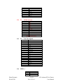
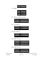
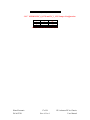
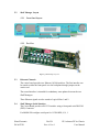
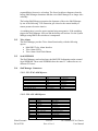
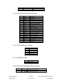
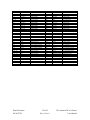
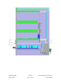
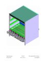
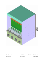
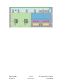
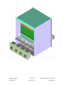
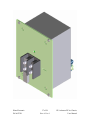
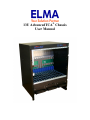
13U AdvancedTCA® Chassis
User Manual
TABLE of CONTENTS
DESCRIPTION
PAGE
TABLE of CONTENTS _________________________________________________ 2
List of Figures ________________________________________________________ 3
List of Tables _________________________________________________________ 4
1.0
General Information______________________________________________ 5
1.1
Introduction ____________________________________________________ 5
1.2
References______________________________________________________ 5
1.3
Company Overview ______________________________________________ 5
1.4
Features of the 14 Slot AdvancedTCA® chassis. _________________________ 6
2.0
System Specifications _____________________________________________ 7
2.1
Mechanical Dimensions ___________________________________________ 7
2.1.1Front View _______________________________________________________________7
2.1.2Side View with side panel removed _____________________________________________8
2.1.3Rear View ________________________________________________________________9
2.2
Cooling Capacity ________________________________________________ 9
2.3
Removable Fan Trays _____________________________________________ 9
2.4
Fan Speed Control Signal _________________________________________ 10
2.5
Fan Tray Present Signals _________________________________________ 10
3.0
Backplane Specifications _________________________________________ 11
3.1
Mechanical Drawing _____________________________________________ 11
3.2
Logical to Physical Slot Mapping ___________________________________ 11
3.3
Base Interface __________________________________________________ 12
3.4
Fabric Interface ________________________________________________ 13
3.5
Update Channel Interface _________________________________________ 13
3.6
IPMB Interface _________________________________________________ 13
3.7
Shelf Manager Slots _____________________________________________ 14
3.8
Serial EEPROMs _______________________________________________ 14
3.9
AdvancedTCA® Backplane Connectors ______________________________ 14
3.9.1P1 PEM Connector ________________________________________________________ 14
3.9.2P2 PEM Connector ________________________________________________________ 14
3.9.3P3 PEM Connector ________________________________________________________ 14
3.9.4P4 PEM Connector _______________________________________________________ 15
3.9.5P5 Fan Tray Signals _______________________________________________________ 15
3.9.6SHMC 1 ________________________________________________________________ 15
3.9.7SHMC 2 ________________________________________________________________ 16
3.9.8RING_1 and RING_2 Connectors_____________________________________________ 16
3.9.9MT_1 Connector __________________________________________________________ 16
3.9.10MT_2 Connector _________________________________________________________ 16
Elma Electronic
DCA052741
2 of 38
Rev A Ver. 0
13U AdvancedTCA® Chassis
User Manual
3.9.11IPMB_1 Connector _______________________________________________________ 16
3.9.12IPMB_2 Connector _______________________________________________________ 16
3.9.17EEPROM I2C_0_CFG and I2C_1_CFG Jumper Configuration ____________________ 17
4.0
Power Distribution ______________________________________________ 18
4.1
Introduction ___________________________________________________ 18
4.2
Power Distribution diagram _______________________________________ 18
5.0
Shelf Manager __________________________________________________ 19
5.1
Introduction ___________________________________________________ 19
5.2
Shelf Manager Layout ___________________________________________ 20
5.2.1Front Panel Layout ________________________________________________________ 20
5.2.2Top View ________________________________________________________________ 20
5.3
Ethernet Channels ______________________________________________ 20
5.4
Shelf Manager Serial Interface _____________________________________ 20
5.5
Thermal and System Management Controller _________________________ 21
5.6
Temperature Monitor____________________________________________ 21
5.7
Front Panel Reset _______________________________________________ 21
5.8
Hardware monitoring and control __________________________________ 21
5.9
Hot Swap Interface ______________________________________________ 21
5.10
Hardware Address ______________________________________________ 21
5.11
Redundancy Control_____________________________________________ 21
5.12
Telco Alarm ___________________________________________________ 22
5.13
Serial EEPROM ________________________________________________ 22
5.14
Shelf Manager Connectors ________________________________________ 22
5.14.1CN3 JTAG ARM Injectors__________________________________________________ 22
5.14.2CN8 AUX ARM Injector ___________________________________________________ 22
5.14.3CN14 Serial and Telco Alarm Connector ______________________________________ 23
5.14.4CN9 10/100 Ethernet Connector _____________________________________________ 23
5.14.7CN2 Battery Backup ______________________________________________________ 23
5.14.8JP1 and JP2 Shelf Manager Ethernet Jumpers__________________________________ 23
5.14.9Backplane Interface Connector______________________________________________ 24
6.0
Revision History ________________________________________________ 26
Appendix A. Chassis Figures ____________________________________________ 27
List of Figures
Figure 2_1 Chassis Front Mechanical View
Figure 2_2 Chassis Side Mechanical View
Figure 2_3 Chassis Rear Mechanical View
Figure 2_4 Fan Tray View
Figure 3_1 Backplane Mechanical Drawing
Figure 5_1 Shelf Manager Locations
Figure 5_2 Shelf Manager Front Panel
Elma Electronic
DCA052741
3 of 38
Rev A Ver. 0
7
8
9
10
11
19
20
13U AdvancedTCA® Chassis
User Manual
Figure 5_3 Shelf Manager Top View
20
List of Tables
Table 3_1 Logical to Physical Slot Mapping
Table 3_2 Base Interface
Table 3_3 Fabric Interface
Table 3_ 4 Update Channel Interface
Table 3_5 P1 PEM Connector
Table3_ 6 P2 PEM Connector
Table 3_7 P3 PEM Connector
Table 3_8 P4 PEM Connector
Table 3_9 P5 Fan Tray Signals Connector
Table 3_10 ShMC 1
Table 3_11 ShMC 2
Table 3_12 Ring Connectors
Table 3_13 MT_1 Connector
Table 3_14 MT_2 Connector
Table 3_15 IPMB_1 Connectors
Table 3_16 IPMB_2 Connector
Table 3_17 I²C Serial EEPROM Jumper Configuration
Table 4_1 Power Distribution Table
Table 5_1 Hardware Address
Table 5_2 CN3 JTAG Connector
Table 5_3 CN8 AUX Connector
Table 5_4 CN14 Serial and Telco Alarm Connector
Table 5_5 CN9 10/100 Ethernet Connector
Table 5_6 CN2 Battery
Table 5_7 JP1 and JP2 Ethernet Jumpers
Table 5_8 Backplane Interface Connector
Table 6_1 Revision History
Elma Electronic
DCA052741
4 of 38
Rev A Ver. 0
11
12
13
13
14
14
15
15
15
16
16
16
16
16
16
17
17
18
21
22
23
23
23
23
23
25
26
13U AdvancedTCA® Chassis
User Manual
1.0
General Information
1.1
Introduction
This document will describe the Second Generation 14 Slot AdvancedTCA®
chassis. This chassis consist of an AdvancedTCA® Backplane, Redundant Shelf
Mangers, Power Entry Modules, and Fan Trays.
1.2
References
1.3
•
PICMG 3.0 Revision 2.0 AdvancedTCA® Base Specification.
•
ELMA Electronic Shelf Manager Application Notes.
•
ELMA Bustronic 14 Slot Dual Star AdvancedTCA® Backplane.
•
ELMA Electronic Shelf Manager Technical Specifications.
•
Pigeon Point Systems IPM Sentry Shelf- External Reference.
Company Overview
Elma Electronic Inc. is an industry innovator in the design and manufacture of
electronic enclosures and passive electronic components. Elma USA has achieved
a leading position in the CPCI, VME/VME64x, VXI, VXS, PXI,
AdvancedTCA®, Switched Fabrics, PCI and Rugged COTS packaging markets.
Elma's component products consist of switches, knobs, and LED arrays.
Headquartered in Switzerland, with offices in 22 countries, Elma has the ability to
respond rapidly, with superior solutions to the requirements of its customers.
Elma has a broad base of customers throughout the United States in diverse
industries such as telecommunications, industrial control, medical electronics,
military and defense.
Elma Electronic Inc. strives to provide products superior in quality, reliability,
performance, and consistently presents new, innovative designs to the market.
Elma's product line encompasses well over 16,000 parts, including enclosures,
cabinets, high quality switches, LED arrays, knobs and much more. Elma also
offers design/integration services backed by responsive and knowledgeable
technical support.
Elma's leading quality level is reached through training of all employees and
following of systematic procedures per ISO 9001 standards to which Elma has
been certified.
Elma Electronic
DCA052741
5 of 38
Rev A Ver. 0
13U AdvancedTCA® Chassis
User Manual
1.4
Features of the 14 Slot AdvancedTCA® chassis.
Elma Electronic
DCA052741
•
Dimensions 13 U X 15.75” X 17”.
•
Rack Mounting Brackets.
•
Universal Handles.
•
14 slot Dual Star AdvancedTCA® Backplane.
•
2 dedicated Shelf Managers.
•
Cooling for 240 Watts per Front Board.
•
3 removable fan trays.
•
2 Seria l EEPROMs for Shelf FRU Information.
•
6 fans 330 CFM each.
•
4 Filtered Power Entry Modules.
•
Front and Rear Cable Bracket.
6 of 38
Rev A Ver. 0
13U AdvancedTCA® Chassis
User Manual
2.0
System Specifications
2.1
Mechanical Dimensions
2.1.1
Front View
Figure 2_1 Chassis Front Mechanical View
Elma Electronic
DCA052741
7 of 38
Rev A Ver. 0
13U AdvancedTCA® Chassis
User Manual
2.1.2
Side View with side panel removed
Figure 2_2 Chassis Side Mechanical View
Elma Electronic
DCA052741
8 of 38
Rev A Ver. 0
13U AdvancedTCA® Chassis
User Manual
2.1.3
Rear View
Figure 2_3 Chassis Rear Mechanical View
2.2
Cooling Capacity
This chassis has to capability to cool 240 Watts per slot. This is accomplished by
using 6 330 CFM fans in 3 removable Fan Trays.
2.3
Removable Fan Trays
This chassis has 3 removable fan trays. Three Fan trays are located below the card
cage. These fan trays have an LED to detect a fan failure.
Elma Electronic
DCA052741
9 of 38
Rev A Ver. 0
13U AdvancedTCA® Chassis
User Manual
Figure 2_4 Fan Tray View
2.4
Fan Speed Control Signal
Combined with the shelf manager the chassis can control and monitor the speed
of the fans.
2.5
Fan Tray Present Signals
Each Fan Tray has a signal that will alert the Shelf Manager. A low signal will
alert that the Fan Tray is present. A high signal will alert that the Fan Tray has
been removed.
Elma Electronic
DCA052741
10 of 38
Rev A Ver. 0
13U AdvancedTCA® Chassis
User Manual
3.0
Backplane Specifications
3.1
Mechanical Drawing
Figure 3_1 Backplane Mechanical Drawing
3.2
Logical to Physical Slot Mapping
The physical slots are numbered from left to right. The logical slots are numbered
1 through 14. See the table below for the physical to logical slot mapping.
Physical Slot
Logical Slot
HW -Address
(hex)
IPMB- Address
(hex)
1
13
4D
2
11
4B
3
9
49
4
7
47
5
5
45
6
3
43
7
1
41
8
2
42
9
4
44
10
6
46
11
8
48
12
10
4A
13
12
4C
14
14
4E
9A
96
92
8E
8A
86
82
84
88
8C
90
94
98
9C
Table 3_1 Logical to Physical Slot Mapping
Elma Electronic
DCA052741
11 of 38
Rev A Ver. 0
13U AdvancedTCA® Chassis
User Manual
3.3
Logical
Slot #
Base
Ch. 1
Base
Ch. 2
Base
Ch. 3
Base
Ch. 4
Base
Ch. 5
Base
Ch. 6
Base
Ch. 7
Base
Ch. 8
Base
Ch. 9
Base
Ch. 10
Base
Ch. 11
Base
Ch. 12
Base
Ch. 13
Base
Ch. 14
Base
Ch. 15
Base
Ch. 16
Base Interface
Logical slots 1 and 2 are the hub slots for the Dual Star Base Interface.
1
2
3
4
5
6
7
8
9
10
11
12
13
14
15
16
ShMC
ShMC
1-3
1-4
1-5
1-6
1-7
1-8
2-2
1-2
2-3
2-4
2-5
2-6
2-7
2-8
19
29
110
210
111
211
112
212
113
213
114
214
115
215
116
216
3-1
3-2
4-1
4-2
5-1
5-2
6-1
6-2
7-1
7-2
8-1
8-2
9-1
9-2
10-1
10-2
11-1
11-2
12-1
12-2
13-1
13-2
14-1
14-2
15-1
15-2
16-1
16-2
Table 3_2 Base Interface
Elma Electronic
DCA052741
12 of 38
Rev A Ver. 0
13U AdvancedTCA® Chassis
User Manual
3.4
Logical
Slot #
Fabric
Ch. 15
Fabric
Ch. 14
Fabric
Ch. 13
Fabric
Ch. 12
Fabric
Ch. 11
Fabric
Ch. 10
Fabric
Ch. 9
Fabric
Ch. 8
Fabric
Ch. 7
Fabric
Ch. 6
Fabric
Ch. 5
Fabric
Ch. 4
Fabric
Ch. 3
Fabric
Ch. 2
Fabric
Ch. 1
Fabric Interface
Logical slots 1 and 2 are the hub slots for the Dual Star Base Interface.
1
2
3
4
5
6
7
8
9
10
11
12
13
14
15
16
16-2
16-2
15-1
15-2
14-1
14-2
13-1
13-2
12-1
12-2
11-1
11-2
10-1
10-2
9-1
9-2
8-1
8-2
7-1
7-2
6-1
6-2
5-1
5-2
4-1
4-2
3-1
3-2
2-2
2-3
2-4
2-5
2-6
2-7
2-9
1-1
1-2
1-3
1-4
1-5
1-6
1-7
28
18
210
110
211
111
212
112
213
113
214
114
215
115
2-1
1-9
Table 3_3 Fabric Interface
Node
Node
Node
Node
Node
HUB
HUB
Node
Node
Node
Node
Node
Node
Physical
Slot
Logical
Slot
Update
Channel
Update Channel Interface
Node
3.5
1
2
3
4
5
6
7
8
9
10
11
12
13
14
13
11
9
7
5
3
1
2
4
6
8
10
12
14
Table 3_4 Update Channel Interface
3.6
IPMB Interface
The IPMB interfaces are bused to each slot and to both Shelf Manager slots.
Elma Electronic
DCA052741
13 of 38
Rev A Ver. 0
13U AdvancedTCA® Chassis
User Manual
3.7
Shelf Manager Slots
There are two Shelf Manager slots located on the left side of the card cage. These
Shelf Manage r slots are configured for use with two Shelf Managers in redundant
operation.
3.8
Serial EEPROMs
The AdvancedTCA® Backplane has two Serial EEPROMs. The Serial EEPROMs
are used to keep the Shelf Fru Information for the Shelf Manager. Both
EEPROMs are set to the same hex address (0xa4). These EEPROMs are accessed
on two different I² C buses.
3.9
AdvancedTCA® Backplane Connectors
3.9.1
P1
PEM Connector
Pin
1
2
3
4
5
6
7
8
9
10
11
12
13
14
3.9.2
P2
PEM Connector
Pin
1
2
3
4
5
6
7
8
9
10
11
12
13
14
3.9.3
P3
Signal
PEM 1
GND
GND
GND
GND
GND
I2C 2 SDA
I2C 2 SCL
GND
5V Out
I2C 3 SDA
I2C 3 SCL
GND
5V Out
Table 3_6 P2 P EM Connector
PEM Connector
Pin
1
2
3
4
5
Elma Electronic
DCA052741
Signal
PEM 0
GND
GND
GND
GND
GND
I2C 2 SDA
I2C 2 SCL
GND
5V Out
I2C 3 SDA
I2C 3 SCL
GND
5V Out
Table 3_5 P1 PEM Connector
Signal
PEM 2
GND
GND
GND
GND
14 of 38
Rev A Ver. 0
13U AdvancedTCA® Chassis
User Manual
GND
I2C 2 SDA
I2C 2 SCL
GND
5V Out
I2C 3 SDA
I2C 3 SCL
GND
5V Out
Table 3_7 P3 PEM Connector
6
7
8
9
10
11
12
13
14
3.9.4
P4
PEM Connector
Pin
Signal
PEM 3
GND
GND
GND
GND
GND
I2C 2 SDA
I2C 2 SCL
GND
5V Out
I2C 3 SDA
I2C 3 SCL
GND
5V Out
Table 3_8 P4 PEM Connector
1
2
3
4
5
6
7
8
9
10
11
12
13
14
3.9.5
P5
Fan Tray Signals
Pin
1
2
3
4
5
6
7
8
9
10
11
12
13
14
15
16
17
18
19
20
21
22
23
24
3.9.6
Signal
Tach 0
Tach 1
Tach 2
Tach 3
Tach 4
Tach 5
Tach 6
PWM 0 Out
PWM 1 Out
PWM 2 Out
PWM 3 Out
FTP 0
FTP 1
FTP 2
FTP 3
FTP 4
FTP 5
Filter 0
Filter 1
Filter 2
FTF Out 0
FTF Out 1
FTF Out 2
GND
Table 3_9 P5 Fan Tray Signals
SHMC_1
Pin
1
2
3
Elma Electronic
DCA052741
Description
TX +
TX RX +
15 of 38
Rev A Ver. 0
13U AdvancedTCA® Chassis
User Manual
3.9.7
3.9.8
Unused pair
RX Unused pair
Table 3_10 ShMC 1
Pin
1
2
3
4, 5
6
7, 8
Description
TX +
TX RX +
Unused pair
RX Unused pair
Table 3_11 ShMC 2
SHMC_2
RING_1 and RING_2 Connectors
Pin
1
2
3
4
3.9.9
4, 5
6
7, 8
Signal
-RNG_A
RRTN_A
-RNG_B
RRTN_B
Table 3_12 RING Connectors
MT_1 Connector
Pin
1
2
3
4
Signal
MT1_TIP
MT1_TIP
MT1_RING
MT1_RING
Table 3_13 MT_1 Connector
3.9.10 MT_2 Connector
Pin
1
2
3
4
Signal
MT1_TIP
MT1_TIP
MT1_RING
MT1_RING
Table 3_14 MT_2 Connector
3.9.11 ICMB_1 Connector
Pin
1
2
3
4
5
Signal
SCL_A
GND
SDA_A
N/C
N/C
Table 3_15 IPMB_1 Connector
3.9.12 ICMB_2 Connector
Pin
1
2
3
4
Elma Electronic
DCA052741
Signal
SCL_A
GND
SDA_A
N/C
16 of 38
Rev A Ver. 0
13U AdvancedTCA® Chassis
User Manual
5
N/C
Table 3_16 IPMB_2 Connector
3.9.17 EEPROM I2C_0_CFG and I2C_1_CFG Jumper Configuration
High
Signal
WP
X
A0
X
A1
X
A2
Table 3_17 I²C Serial EEPROM Jumper Configuration
Elma Electronic
DCA052741
Low
X
17 of 38
Rev A Ver. 0
13U AdvancedTCA® Chassis
User Manual
4.0
Power Distribution
4.1
Introduction
Four Power Entry Modules are used to provide power to the backplane. These
modules are designated as A1, A2, B1, and B2. The table below shows the logical
and physical slots where the Power Entry Module is assigned.
These four Power Entry Modules are intended to provide noise reduction in
Telecommunications DC Power. The Filter is non-polarized. Markings indicate
the polarity to be connected to the AdvancedTCA® Backplane.
4.2
Power Distribution diagram
Physical
Slot
Logical
Slot
Power
Source
Elma Electronic
DCA052741
1
2
3
4
5
6
7
8
9
10
11
12
13
14
13
11
9
7
5
3
1
2
4
6
8
10
12
14
A2
B2
A1
B1
A2
B2
A1 A1 A1 A1 A2
A2 A2
B1 B1 B1
B1 B2
B2
B2
Table 4_1 Power Distribution Table
A1
B1
A2
B2
A1
B1
A2
B2
18 of 38
Rev A Ver. 0
13U AdvancedTCA® Chassis
User Manual
5.0
Shelf Manager
5.1
Introduction
The Shelf Manager is an 18.4mm wide, 2.5U high, and 280mm deep card that
incorporates the Pigeon Point IPM Sentry. The Shelf Managers are located on the
left side in the card cage area.
Figure 5_1 Shelf Manager Locations
Elma Electronic
DCA052741
19 of 38
Rev A Ver. 0
13U AdvancedTCA® Chassis
User Manual
5.2
Shelf Manager Layout
5.2.1
Front Panel Layout
Figure 5_2 Shelf Manager Front Panel
5.2.2
Top View
Figure 5_3 Shelf Manager Top View
5.3
Ethernet Channels
The carrier board provides two Ethernet 10/100 interfaces. The first interface can
be routed to either the front panel or to the backplane through jumpers on the
carrier card.
The second interface is intended for redundancy state updates between the two
Shelf Managers.
These Ethernet signals are also routed to Logical Slots 1 and 2.
5.4
Shelf Manager Serial Interface
The Carrier Board provides a RS-232 interface using a front panel mini DB-25M
(DTE) Connector.
For ShMM 500 configure serial port for 115200 BPS, 8, N, 1.
Elma Electronic
DCA052741
20 of 38
Rev A Ver. 0
13U AdvancedTCA® Chassis
User Manual
5.5
Thermal and System Management Controller
The ADM1026 is used to control and monitor the Fan trays. This device has
Voltage Monitoring, Tachometer inputs, PWM outputs, and Fan Tray Present
signals. This device will control the speed of the fans.
5.6
Temperature Monitor
The Shelf Manager has the ability to monitor I²C temperature sensors. The LM75
I²C temperature sensors are generally used for temperature monitoring.
5.7
Front Panel Reset
The carrier board provides a reset button on the front panel. Activation of the
button results in a full board reset, which is equivalent of power cycling the board.
5.8
Hardware monitoring and control
The Shelf Manager can monitor input voltage, Temperature Sensors, Fan Tray
Present Signals, Fan Tachometer inputs, and PWM Outputs.
5.9
Hot Swap Interface
The Shelf Manager has a hot swap interface. This interface has three components
the Extraction Handle, The Present Signal (This signal indicates that the Shelf
Manager is fully seated in the backplane), and the Hot Swap LED.
5.10
Hardware Address
The hardware address for the Shelf Manager is configured by the backplane. The
Shelf Manager provides a pull up resistor for the address line and the backplane
will configure the hardware address when the Shelf Manager is plugged in to the
backplane.
HA [1]
0
1
0
1
HA [2]
0
0
1
1
Description
Error
First Management Slot
Second Management Slot
Error
Table 5_1 Hardware Address
If the hardware address is not configured the Shelf Manager will not become
active.
5.11
Redundancy Control
The active Shelf Manager manages the IPMB and the IPM Controllers. The active
Shelf Manger interacts with the backup System Manager over RMCP and other
shelf external interfaces. The active Shelf Manager maintains an open TCP/IP
connection (eth1) with the backup Shelf Manager. It communicates all changes in
the state of managed objects to the backup Shelf Manager.
The backup Shelf Manager may become active as the result of a switchover.
There are two types of switchover cooperative and forced. The cooperative
switchover the active and backup Shelf Managers negotiate the transfer of
Elma Electronic
DCA052741
21 of 38
Rev A Ver. 0
13U AdvancedTCA® Chassis
User Manual
responsibilities from active to backup. The forced switchover happens when the
backup Shelf Manager determines that the active Shelf Manager is no longer alive
or healthy.
The backup Shelf Manger recognizes the departure of the active Shelf Manager
by one of the following. TCP connection gets closed or the remote healthy or
remote presence becomes inactive.
A watchdog timer is used to protect against being unresponsive. If the watchdog
triggers the Shelf Manager will reset and the backup will activate. For the System
Manager using RMCP the switchover is transparent.
5.12
Telco Alarm
The Shelf Manager provides Telco Alarm Functionality with the following
aspects.
• Mini DB25 Telco Alarm Interface
• Telco Alarm LED’s
• Telco Alarm Cutoff Push Button
5.13
Serial EEPROM
The Shelf Manager can load and store the Shelf FRU Information on the externa l
Serial EEPROM. These serial EEPROMs have the same I²C Address but are on
different I²C busses.
5.14
Shelf Manager Connectors
5.14.1 CN3 JTAG ARM Injectors
Pin
1
3
5
7
8
11
2, 4, 6, 8, 10, 12, 13, 14
Signal
N/C
/TRST
TDI
TMS
TCK
TDO
NC / Ground
Table 5_2 CN3 JTAG Connector
Description
No Connection
Test Power Reset
Test Data In
Test Mode Select
Test Clock
Test Data Out
Ground
5.14.2 CN8 AUX ARM Injector
Pin
1
3
4
5
6
7
8
9
10
11
12
13
Elma Electronic
DCA052741
Signal
V5
nMRST
GND
UMODE
GND
NC
GND
SEL_JTG_DEV
GND
TD
NC
RD
Description
+ 5 Volts
Master Reset
Ground
User Mode
Ground
No Connection
Ground
JTAG Target Control
Ground
Transmit Data
No Connection
Receive Data
22 of 38
Rev A Ver. 0
13U AdvancedTCA® Chassis
User Manual
14
15
2, 16
NC
NC
GND
No Connection
No Connection
Ground
Table 5_3 CN8 AUX Connector
5.14.3 CN14 Serial and Telco Alarm Connector
Pin
1
2
3
4
5
6
7
8
9
10
11
12
13
14
15
16
17
18
19
20
21
22
23
24
25
Signal
Description
AMIR+
Minor Reset +
AMIRMinor Reset AMAR+
Major Reset +
AMARMajor Reset ACNO
Critical Alarm Normally Open
ACNC
Critical Alarm Normally Closed
ACCOM
Critical Alarm Common
AMINO
Minor Alarm Normally Open
CD
Carrier Detect
RxD
Receive Data
TxD
Transmit Data
DTR
Data Terminal Ready
SG
Signal Ground
AMINNC
Minor Alarm Normally Cloased
AMINCOM
Minor Alarm Common
AMANO
Major Alarm Normally Open
AMANC
Major Alarm Normally Closed
AMACOM
Major Alarm Common
APRCO
Power Alarm Normally Open
APRCOM
Power Alarm Common
NC
No Connection
DSR
Data Set Ready
RTS
Request to Send
CTS
Clear to Send
RI
Ring Indicator
Table 5_4 CN14 Serial and Telco Alarm Connector
5.14.4 CN9 10/100 Ethernet Connector
Pin
Description
TX +
1
TX 2
RX +
3
Unused pair
4, 5
RX 6
Unused pair
7, 8
Table 5_5 CN9 10/100 Ethernet Connector
5.14.7 CN2 Battery Backup
Pin
1
2
Description
+3.3 V Battery
GND
Table 5_6 CN2 Battery
5.14.8 JP1 and JP2 Shelf Manager Ethernet Jumpers
JP1
1-3, 2-4
3-5, 4-6
Elma Electronic
DCA052741
JP2
Description
Ethernet 0 is routed to Front Panel
1-3, 2-4
Ethernet 0 is routed to Backplane
3-5, 4-6
Table 5_7 JP1 and JP2 Ethernet Jumpers
23 of 38
Rev A Ver. 0
13U AdvancedTCA® Chassis
User Manual
5.14.9 Backplane Interface Connector
Pin
1, 2
3
4
5
6
7
8
9
10
11, 12
13, 14
15
16
17
18
19
20
21, 22
23
24
25
26
27
28
29
30
31, 32
33
34
35
36, 37
38
39
40
41
42, 43
44
45
46, 47
48
49
50, 51
52
53
54, 55
56
57, 58
59
60
61, 62
63
64
65
66
67
68
69
70
71, 72
73
74
75
Designation
Gnd
FTFOUT_0
FTFOUT_1
FTFOUT_2
FTFOUT_3
FTFOUT_4
FTFOUT_5
FTFOUT_6
FTFOUT_7
Gnd
5V out
SDA_B16
SCL_B16
SCL_A13
SDA_A11
SCL_B11
SDA_B8
Gnd
SCL_A8
SDA_A6
SCL_B6
SDA_B3
SCL_A3
SDA_A11
SCL_B2
SDA_B1
Gnd
SCL_A15
SDA_B15
SCL_B15
Gnd
E0RN
E0RP
RX1N
RX1P
N/C
Tach_1
Tach_0
N/C
-48B1 Sense
-48B1 RTN Sense
N/C
-48A1 Sense
-48A1 RTN Sense
N/C
PWM0 Out
N/C
-48V A
-48V A RTN
Gnd
PEM0
PEM1
PEM2
PEM3
PEM4
PEM5
I 2 C 0 SDA
I 2 C 0 SCL
Gnd
I 2 C 2 SDA
I 2 C 2 SCL
SDA_B7
Elma Electronic
DCA052741
Purpose
Logic Ground
Fan Tray Fail Signal
Fan Tray Fail Signal
Fan Tray Fail Signal
Fan Tray Fail Signal
Fan Tray Fail Signal
Fan Tray Fail Signal
Fan Tray Fail Signal
Fan Tray Fail Signal
Logic Ground
5 Volt Output
Radial IPMB
Radial IPMB
Radial IPMB
Radial IPMB
Radial IPMB
Radial IPMB
Logic Ground
Radial IPMB
Radial IPMB
Radial IPMB
Radial IPMB
Radial IPMB
Radial IPMB
Radial IPMB
Radial IPMB
Logic Ground
Radial IPMB
Radial IPMB
Radial IPMB
Logic Ground
Ethernet 0 Rx Ethernet 0 Rx+
Ethernet 1 Rx Ethernet 1 Rx+
No Connection
Fan Tachometer Signal
Fan Tachometer Signal
No Connection
-48B1 Sense
-48B1 RTN Sense
No Connection
-48A1 Sense
-48A1 RTN Sense
No Connection
Fan PWM Signal
No Connection
-48V A Input
-48V A Return
Logic Ground
PEM Present Signal
PEM Present Signal
PEM Present Signal
PEM Present Signal
PEM Present Signal
PEM Present Signal
Off Board I2 C Bus
Off Board I2 C Bus
Logic Ground
Off Board I2 C Bus
Off Board I2 C Bus
Radial IPMB
Pin
123
124
125
126
127
128
129
130
131, 132
133
134
135
136
137
138
139
140
141, 142
143
144
145
146
147
148
149
150
151, 152
153
154
155
156, 157
158
159
160
161
162, 163
164
165
166, 167
168
169 - 171
172
173 - 175
176
177 - 179
180
181
182
183
184
185
186
187
188
189
190
191
192
193
194
195
196
24 of 38
Rev A Ver. 0
Designation
FTP_1
FTP_0
Filter 1
Filter 2
Filter 3
SDA_B13
I 2 C 1 SDA
I 2 C 1 SCL
Gnd
I 2 C 3 SCL
I 2 C 2 INT
SDA_A16
SCL_A16
SCL_B13
SDA_A13
SCL_A11
SDA_B11
Gnd
SCL_B8
SDA_A8
SCL_A6
SDA_B6
SCL_B3
SDA_A3
SCL_A1
SDA_B2
Gnd
SCL_B1
SDA_A15
HWA2
Gnd
TX1N
TX1P
USBDP
USBDM
N/C
Tach_6
Tach_7
N/C
-48B2 Sense
N/C
-48A2 Sense
N/C
PWM2 Out
N/C
-48 B RTN
FTP 3
FTP 2
PRES L L
PRES R L
HLY R L
HLY L L
SWR R L
SWR L L
PRES L
SDA_B12
FTP 4
FTP 5
Filter 0
I 2 C 3 SDA
I 2 C 3 INT
SCL_A2
Purpose
Fan Tray Present Signal
Fan Tray Present Signal
Air Filter Present Signal
Air Filter Present Signal
Air Filter Present Signal
Radial IPMB
Off Board I2 C Bus
Off Board I2 C Bus
Logic Ground
Off Board I2 C Bus
Off Board I2 C Bus
Radial IPMB
Radial IPMB
Radial IPMB
Radial IPMB
Radial IPMB
Radial IPMB
Logic Ground
Radial IPMB
Radial IPMB
Radial IPMB
Radial IPMB
Radial IPMB
Radial IPMB
Radial IPMB
Radial IPMB
Logic Ground
Radial IPMB
Radial IPMB
Logic Ground
Ethernet 1 TXEthernet 1 TX+
Secondary USB+
Secondary USBNo Connection
Fan Tachometer Signal
Fan Tachometer Signal
No Connection
-48B2 Sense
No Connection
-48A2 Sense
No Connection
Fan PWM Signal
No Connection
-48 B RTN
Fan Tray Present
Fan Tray Present
Present Signal L
Present Signal R
Healthy Signal R
Healthy Signal L
Switchover Signal R
Switchover Signal L
Present Signal
Radial IPMB
Fan Tray Present
Fan Tray Present
Air Filter Present Signal
Off Board I2 C Bus
Off Board I2 C Bus
Radial IPMB
13U AdvancedTCA® Chassis
User Manual
Pin
76
77
78
79
80
81, 82
83
84
85
86
87
88
89
90
91, 92
93
94
95
96, 97
98
99
100 - 102
103
104
105
106
107, 108
109
110 - 112
113
114, 115
116
117, 118
119
120
121, 122
Designation
SCL_B7
SCL_B12
SDA_A12
SCL_B14
SDA_A14
Gnd
SCL_A10
SDA_B10
SCL_B9
SDA_A9
SCL_A5
SDA_B5
SCL_B4
SDA_A4
Gnd
SCL_A
SDA_B
SCL_B
Gnd
E0TM
E0TP
N/C
Tach_5
Tach_3
Tach_4
Tach_2
N/C
-48B2 RTN Sense
N/C
-48A2 RTN Sense
N/C
PWM1 Out
N/C
-48V B
N/C
Gnd
Elma Electronic
DCA052741
Purpose
Pin
Designation
Radial IPMB
197
SDA_A2
Radial IPMB
198
SCL_A7
Radial IPMB
199
SDA_A7
Radial IPMB
200
SDA_B14
Radial IPMB
201
SCL_A12
Logic Ground
202
FTP 6
Radial IPMB
203
FTP 7
Radial IPMB
204
SDA_A10
Radial IPMB
205
SCL_A14
Radial IPMB
206
SDA_B9
Radial IPMB
207
SCL_B10
Radial IPMB
208
SDA_A5
Radial IPMB
209
SCL_A9
Radial IPMB
210
SDA_B4
Logic Ground
211
SCL_B5
IPMB A
212, 213
Gnd
IPMB B
214
SDA_A
IPMB B
215
SCL_A4
Logic Ground
216
HWA1
Ethernet 0 TX 217, 218
Gnd
Ethernet 0 TX +
219
USB0P
No Connection
220
USB0M
Fan Tachometer Signal
221 - 223
N/C
Fan Tachometer Signal
224
Tach_9
Fan Tachometer Signal
225
Tach_11
Fan Tachometer Signal
226
Tach_8
No Connection
227
Tach_10
-48B2 RTN Sense
228, 229
N/C
No Connection
230
-48B3 RTN Sense
-48A2 RTN Sense
231
-48B3 Sense
No Connection
232, 233
N/C
Fan PWM Signal
234
-48A3 RTN Sense
No Connection
235
-48A3 Sense
-48V B Input
236, 237
N/C
No Connection
238
PWM3 Out
Logic Ground
239, 240
N/C
Table 5_8 Backplane Interface Connector
25 of 38
Rev A Ver. 0
Purpose
Radial IPMB
Radial IPMB
Radial IPMB
Radial IPMB
Radial IPMB
Fan Tray Present
Fan Tray Present
Radial IPMB
Radial IPMB
Radial IPMB
Radial IPMB
Radial IPMB
Radial IPMB
Radial IPMB
Radial IPMB
Logic Ground
IPMB A Signal
Radial IPMB
Hardware Address
Logic Ground
Primary USB +
Primary USB No Connection
Fan Tachometer Signal
Fan Tachometer Signal
Fan Tachometer Signal
Fan Tachometer Signal
No Connection
-48B3 RTN Sense
-48B3 Sense
No Connection
-48A3 RTN Sense
-48A3 Sense
No Connection
Fan PWM Signal
No Connection
13U AdvancedTCA® Chassis
User Manual
6.0
Revision History
Description of Change
Document
Initial release
Document ID
Date
Preliminary Revision A Version 0
05/18/07
Table 6_1 Revision History
Elma Electronic
DCA052741
26 of 38
Rev A Ver. 0
13U AdvancedTCA® Chassis
User Manual
Appendix A. Chassis Figures
Elma Electronic
DCA052741
27 of 38
Rev A Ver. 0
13U AdvancedTCA® Chassis
User Manual
Elma Electronic
DCA052741
28 of 38
Rev A Ver. 0
13U AdvancedTCA® Chassis
User Manual
Elma Electronic
DCA052741
29 of 38
Rev A Ver. 0
13U AdvancedTCA® Chassis
User Manual
Elma Electronic
DCA052741
30 of 38
Rev A Ver. 0
13U AdvancedTCA® Chassis
User Manual
Elma Electronic
DCA052741
31 of 38
Rev A Ver. 0
13U AdvancedTCA® Chassis
User Manual
Elma Electronic
DCA052741
32 of 38
Rev A Ver. 0
13U AdvancedTCA® Chassis
User Manual
Elma Electronic
DCA052741
33 of 38
Rev A Ver. 0
13U AdvancedTCA® Chassis
User Manual
Elma Electronic
DCA052741
34 of 38
Rev A Ver. 0
13U AdvancedTCA® Chassis
User Manual
Elma Electronic
DCA052741
35 of 38
Rev A Ver. 0
13U AdvancedTCA® Chassis
User Manual
Elma Electronic
DCA052741
36 of 38
Rev A Ver. 0
13U AdvancedTCA® Chassis
User Manual
Elma Electronic
DCA052741
37 of 38
Rev A Ver. 0
13U AdvancedTCA® Chassis
User Manual
Elma Electronic
DCA052741
38 of 38
Rev A Ver. 0
13U AdvancedTCA® Chassis
User Manual