1
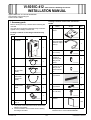
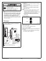
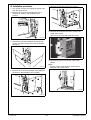
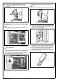
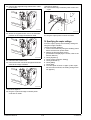
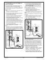
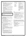
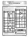
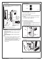
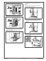
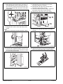
VI-505/IC-412 Video Interface Kit/Image Controller
INSTALLATION MANUAL
Index
VI-505/IC-412 (d-Color MF360/MF280)
I. Accessory parts ................................................................................................................. 1
II. Part names ......................................................................................................................... 2
III. Installation procedures ....................................................................................................... 3
IV. Specifying the copier settings ............................................................................................ 6
V. Connecting the copier and image controller to a network................................................... 7
VI. Specifying basic image controller settings (IP address) .................................................... 8
VII.Checking the setup with a test print ................................................................................... 8
VI-505/IC-412 (d-Color MF651/MF551/MF451)
I. Accessory parts ............................................................................................................... 11
II. Part names ....................................................................................................................... 12
III. Installation procedures ..................................................................................................... 12
IV. Specifying the copier settings .......................................................................................... 17
V. Connecting the copier and image controller to a network................................................. 18
VI. Specifying basic image controller settings (IP address) .................................................. 19
VII.Checking the setup with a test print ................................................................................. 20
Y110511-5
E-i
Installation Manual
This page is intentionally left blank.
Installation Manual
E-ii
Y110511-5
VI-505/IC-412
INSTALLATION MANUAL
Video Interface Kit/Image Controller
Applied Machines: d-Color MF360/MF280
COLOR MFP: 36 ppm/28 ppm
Product Code: A0ED
I. Accessory parts
Package contents of the video interface kit
VI-505
Before starting to set up, check that the following are
included.
Only the parts required to install the image controller
appear in the package contents list.
No.
Name
Shape
1. Relay circuit
board
Package contents of the image controller Fiery
IC-412
No.
Name
Shape
Q’ty
1
Q’ty
A0YEIXC004DA
1. Image
controller
2. Power cord *
(For connection
between copier
and IC)
1
1
A0YEIXC002DA
3. Screw A *
(4 × 8 mm)
1
4040IXC046DA
4. Shoulder
screws for
mounting the
relay circuit
board
A0YEIXC001DA
2. Power cord A
1
5. Shoulder
screws for the
relay circuit
board connector
A00HIXC019HA
3. Power cord B
*1
(for the wall
outlet)
1
A00HIXE034HA
4. Copier
LAN cable
(crossover
cable)
2
A0YEIXC047DA
6. Upper mounting bracket
1
A00HIXC018HA
A0YEIXC074DA
7. Lower mounting bracket
1
8. Screw B
(3 × 20 mm)
6. Ferrite Core
1
4
9J08IXC075DA
9. Installation
manual
A0YEIXC054DA
-
2
A00HIXC105HB
A0YEIXC003DA
-
1 set
*1 This power cord cannot be used in Taiwan that
utilizes 110V power.
*2 The accessories are not used when installing
the image controller.
Y110511-5
A0YEIXC005DB
1
5. Image
transmission
cable
7. Other accessories *2
2
4980IXC019DA
*
E-1
This part is not used when installing the video
interface kit on d-Color MF360/MF280.
Installation Manual
<Softswitch>
• Lights up when the image controller is running or
is ready to be used.
• When turned on, the image controller system
starts up.
• When turned off, the image controller system
safely shuts down.
Note:
• If the image controller malfunctions or cannot
be shut off with the softswitch, be sure to
unplug the power cord from the electrical outlet
or the machine’s power cord connector.
• Remove the seal from the connector of the
power cord.
After unpacking, be sure to get rid of the
packaging materials and keep them out of
the reach of children.
Putting the head in the plastic bag
involves danger of suffocation.
Note:
This manual provides the illustrations of the accessory parts and machine that may be slightly different in shape from yours. In that case, instead of
the illustrations, use the appearance of your
machine to follow the installation procedure. This
does not cause any significant change or problem
with the procedure.
<Port descriptions>
LAN
Port 2
COPIER
II. Part names
Port 1
Ethernet 10Base-T/100Base-TX/1000Base-T
network port (Port 1)
A00HIXC033HB
Port 1 (For the LAN)
Connect the network cable to the LAN.
Port 2 (For the COPIER)*
Use a crossover cable to connect to the LAN port of
the copier.
* This port is not used, depending on the connection method. Refer to page E-7.
Power
cord connector
Softswitch LED
Image transmission
connector
Copier LAN cable port (Port 2)
A0YEIXC006DA
Installation Manual
E-2
Y110511-5
III. Installation procedures
5. Remove the internal bracket (12 screws).
1. Turn off the machine and unplug the power cord
from the power outlet.
2. Remove the cover from the right side of the
machine as shown in the illustration (four
screws).
A0YEIXC057DA
6. Remove the interface connector cover for the
copier (one screw).
(Do not use the removed connector cover.)
A09NIXC024DA
3. If the fax kit has been installed, loosen the two
screws, and then remove the circuit board from
the copier.
A0YEIXC058DA
7. Remove the two screws for the main circuit
board.
Note:
The two screws removed here will be used to
install the relay circuit board.
A0YEIXC073DA
4. Remove the cover from the back of the machine
as shown in the illustration (four screws).
A0YEIXC014DA
A0YEIXC056DA
Y110511-5
E-3
Installation Manual
11. Using the two screws, secure the relay circuit
board.
Note:
Be sure to use the two screws removed in step 7.
8. Attach the two supplied shoulder screws for
mounting the relay circuit board to the main circuit board.
A0YEIXC015DB
A0YEIXC017DA
9. Flip the switches 1 and 2 up as shown in the illustration.
Note:
If the switches are not flipped up, this option cannot be detected properly.
12. Using the two supplied shoulder screws for the
relay circuit board connector, secure the connector of the relay circuit board.
A0YEIXC018DA
A0YEIXC059DA
13. To install the covers and other parts removed in
steps 4 and 5, reverse the removal procedure.
14. If the fax kit was removed in step 3, install it at
the location from where it was removed.
15. Remove the knockout from the cover removed in
step 2 with nippers.
10. Mount the supplied relay circuit board as shown
in the illustration.
Note:
Align the matchmark of the relay circuit board with
that of the main circuit board. Connect the connector located on the back of the relay circuit board to
the connector on the main circuit board.
Knockout
A0YEIXC061DA
A0YEIXC060DA
Installation Manual
E-4
Y110511-5
19. Connect the furnished power cord to the image
controller power cord connector and secure the
power cord plug with the clamp.
110-127 V regions: power cord B
220-240 V regions: power cord A
Note:
• Be sure to use the furnished power cord.
• Power cord for Taiwan that utilizes 110V power
is not supplied as an accessory part.
16. Install the cover removed in step 2 (four screws).
17. Remove the mounting brackets from the image
controller (five screws).
A0YEIXC064DA
20. Insert the two image controller tabs into the
holes on the machine cover.
A0YEIXC062DA
18. Attach the furnished upper and lower mounting
brackets to the image controller (five screws
removed in step 17).
A0YEIXC065DA
21. Screw the image controller to the cover (four furnished screws B).
Note:
Tighten the two lower screws first.
A0YEIXC063DA
A0YEIXC066DA
Y110511-5
E-5
Installation Manual
<220-240 V regions>
26. Connect the image controller power cord to the
copier.
22. Connect the supplied image transmission cable
to the copier.
A0YEIXC067DA
A0YEIXE072DA
23. Attach the supplied ferrite core to the indicated
position on the image transmission cable.
27. Plug the copier power cord into an outlet.
IV. Specifying the copier settings
From the copier, specify the necessary settings for
using the image controller.
<Image Controller Settings>
1. Turn on the machine by using the auxiliary power
button and the main power switch.
2. Display the Service Mode screen.
(For details on displaying the screen, refer to the
Service Manual.)
3. Touch [System 2].
4. Touch [Image Controller Setting].
5. Touch [Controller 1].
6. Touch [END].
7. Touch [Exit].
8. Turn the copier off, then on again. (If the copier
has not been turned off, the setting changes are
not applied.)
A0YEIXC068DA
24. Close the door of the cover.
25. Connect the other end of the image transmission
cable to the image controller.
A0YEIXC069DA
<110-127 V regions>
26. Plug the copier and image controller power
cords into an outlet.
Installation Manual
E-6
Y110511-5
V. Connecting the copier and image controller to a network
b: Connecting the copier and image controller
with the supplied copier LAN cable (crossover cable), and connecting the image controller to a hub (LAN)
With this connection method, the following copier
function limitations are applied.
• AppleTalk and IPX/SPX protocols
• IPv6, IPsec, browsing for file transmissions
(SMB), and replies to broadcasts
• The 1000Base-T network speed cannot be used.
These functions can be used from the image controller.
The function limitations are not applied to the image
controller.
1. Use the supplied copier LAN cable (crossover
cable) to connect the LAN port of the copier to
port 2 of the image controller.
2. Use a network cable to connect port 1 of the
image controller to the hub (LAN).
The network functions of the copier can be used
even when the image controller is installed.
There are two ways of connecting to a network from
this copier. When connection b is used, some functions are limited.
Note:
Use a network cable (Category 5E or later recommended) to connect to a computer.
a: Connecting the copier and image controller
with separate LAN cables
• With this connection method, the network functions of the copier are not impaired, and the
image controller functions are added.
• The IP address settings for the copier and image
controller are specified separately.
• In order to use the network functions of the
copier, the network settings on the copier must be
specified according to the functions to be used.
1. Use a network cable to connect the LAN port of
the copier to the hub (LAN).
2. Use a network cable to connect port 1 of the
image controller to the hub (LAN).
Note:
Depending on the connection method, the image
controller TCP/IP settings are different. For details,
refer to step 12 in “VI. Specifying basic image controller settings (IP address)”.
Port 1
Port 2
Port 1
A0YEIXC071DA
<Copier Network Settings>
Since the IP address of the copier can be set from
the image controller, it is not necessary to specify
the IP address from the copier. The IP address of
the copier appears at the end of the Configuration
Sheet for the image controller. However, the DHCP
settings must be specified from the copier in order
for the copier and image controller to communicate
internally through the crossover cable.
• Specifying the copier DHCP setting
Utility mode - “Administrator Settings” - “Network
Settings” - “TCP/IP Settings” - “IPv4 Settings” “Auto Input” - “DHCP Settings” - “ON”
• In order to use the network functions of the
copier, the network settings on the copier must be
specified according to the functions to be used.
Port 2
A0YEIXC070DA
Y110511-5
E-7
Installation Manual
12. Specify settings for the following.
Note:
• When manually specifying the IP address of the
image controller
Since the IP address of the copier is one number higher than the IP address of the image
controller, consecutively numbered IP
addresses must be available.
(Example: Image controller: 192.168.1.10;
Copier: 192.168.1.11)
However, “xxx.xxx.xxx.255” cannot be specified
for the IP address of the image controller if it is
set manually.
• When using DHCP to specify the IP address of
the image controller
Use the IP address assigned by the DHCP
server for the IP address of the image controller
and copier
• Depending on the connection method, the
image controller TCP/IP settings are different.
For details, refer to step 12 in “VI. Specifying
basic image controller settings (IP address)”.
Image controller IP address
Subnet Mask:
Subnet mask for the connected network
Gateway
Address:
IP address of the default
gateway
Obtain IP for
Engine:
Set whether to obtain the IP
address of the copier.
The setting is different
depending on the connection method used in
“V. Connecting the copier
and image controller to a
network”.
a: No
b: Yes
Note:
First check with your network administrator for the
settings that should be entered.
With this connection method, be careful of the timing for turning on the image controller and the
copier. For details on the timing, refer to the end of
this manual.
13. Touch [Menu] three times, select “Yes” when
“Save Changes” appears, and then select “OK”.
14. Touch [Printer Setup].
15. Touch [Menu], select “Yes” when “Save
Changes” appears, and then select “OK”.
16. When “Exit Setup” is selected, “Rebooting system” appears and the image controller is
restarted.
17. After the image controller is ready to be used,
turn the copier off, then on again.
VI. Specifying basic image controller settings (IP address)
Specify the default settings for the image controller.
1. Turn on the image controller.
2. Turn on the copier.
3. [Language Setup] appears in the lower center of
the screen in the copier’s touch panel.
4. Press the [Utility/Counter] key on the copier.
5. Touch [Controller Details].
Note:
If [Controller Details] does not appear, wait a short
while, and then repeat steps 3 and 4.
VII. Checking the setup with a test print
After setting up the image controller, print the configuration sheet to check that the controller is operating
correctly.
<To print a test page>
1. Press the [Utility/Counter] key on the copier.
2. Touch [Controller Details].
3. Touch [Menu].
4. Select “Print Pages”.
The names of the pages that can be printed are
displayed.
5. Select “Configuration”.
6. In the Language Setup screen, select the language and market region.
After the settings have been specified, the controller reboots.
7. Touch [Controller Details].
8. When the password is entered, the Setup screen
appears. The default password is “Fiery.1”. (Be
sure to type in the password with the correct capitalization.)
9. Select “Server Setup” in the Controller Details
screen.
10. Without specifying any other settings, touch
[Exit]. When “Save Changes” appears, select
“Yes”, and then select “OK”.
11. In the same way, select “Network Setup”. After
selecting “Protocol Setup”, then “IPv4 Setup”,
select “Ethernet Setup”. Set “Enable Auto IP
Configuration” to “No”, and then select “OK”.
Installation Manual
IP Address:
E-8
Y110511-5
Timing for turning on the copier with connection method b from “V. Connecting the
copier and image controller to a network”
Turning on
Turn on the devices in the following order.
1. Turn on the softswitch on the image controller.
2. Check that the image controller is ready to be
used, and then turn on the copier.
If the copier is turned on too soon, a malfunction
may occur. For details, refer to the following information.
Timing for turning on the copier
With connection b described in “V. Connecting the
copier and image controller to a network”, the copier
and image controller communicate internally through
a crossover cable.
If the DHCP function is enabled on the image controller, the network interface card in the copier performs a DHCP request when it is turned on in order
to acquire the IP address necessary for communicating with the image controller.
Since a DHCP request is performed when the copier
is turned on, the IP address cannot be acquired if
the copier is turned on before the image controller is
ready to be used, preventing communications with
the image controller.
One of the following IP addresses can be assigned
to the copier.
172.17.249.2
10.249.249.2
Y110511-5
E-9
Installation Manual
This page is intentionally left blank.
Y110511-5
E-10
Installation Manual
VI-505/IC-412
INSTALLATION MANUAL
Video Interface Kit/Image Controller
Applied Machines: d-Color MF651/MF551/MF451
COLOR MFP: 65 ppm/55 ppm/45 ppm
Product Code: A0P0/A0P1/A0P2
I. Accessory parts
Before starting to set up, check that the following are
included.
Only the parts required to install the image controller
appear in the package contents list.
Package contents of the image controller Fiery
IC-412
No.
Name
Shape
*3 The accessories are not used when installing
the image controller.
Package contents of the video interface kit
VI-505
No.
Name
Shape
Q’ty
1. Relay circuit
board
Q’ty
1
1. Image
controller
A0YEIXC004DA
2. Power cord *
(For connection
between copier
and IC)
1
1
A0YEIXC002DA
3. Screw *
(4 × 8 mm)
A0YEIXC001DA
2. Power cord *1
1
4040IXC046DA
4. Shoulder
screws for
mounting the
relay circuit
board
1
A00HIXC019HA
3. Power cord *2
(for the wall
outlet)
1
5. Shoulder
screws for the
relay circuit
board connector
A00HIXE034HA
4. Copier
LAN cable
(crossover
cable)
1
2
A0YEIXC005DB
2
A0YEIXC047DA
6. Installation
manual
A00HIXC018HA
5. Image
transmission
cable
1 set
1
4980IXC019DA
*
A0YEIXC003DA
6. Ferrite Core
Using or not using the part depends on each
market.
1
A0YEIXC054DA
7. Other accessories *3
-
After unpacking, be sure to get rid of the
packaging materials and keep them out of
the reach of children.
-
*1 This power cord is not used when installing the
image controller.
*2 This power cord cannot be used in Taiwan that
utilizes 110V power.
Y110511-5
Putting the head in the plastic bag
involves danger of suffocation.
E-11
Installation Manual
II. Part names
<Port descriptions>
Port 1
LAN
Port 2
COPIER
Ethernet 10Base-T/100Base-TX/1000Base-T
network port (Port 1)
A00HIXC033HB
Port 1 (For the LAN)
Connect the network cable to the LAN.
Power
cord connector
Port 2 (For the COPIER)*
Use a crossover cable to connect to the LAN port of
the copier.
* This port is not used, depending on the connection method. Refer to page E-8.
III. Installation procedures
Softswitch LED
Image transmission
connector
1. Turn off the machine and unplug the power cord
from the power outlet.
2. Remove the right side rear upper cover from the
copier (three screws).
Copier LAN cable port (Port 2)
A0YEIXC006DA
<Softswitch>
• Lights up when the image controller is running or
is ready to be used.
• When turned on, the image controller system
starts up.
• When turned off, the image controller system
safely shuts down.
Note:
• If the image controller malfunctions or cannot
be shut off with the softswitch, be sure to
unplug the power cord from the electrical outlet
or the machine’s power cord connector.
• Remove the seal from the connector of the
power cord.
A0YEIXC008DB
3. If the fax kit has been installed, loosen the two
screws, and then remove the circuit board from
the copier.
A0YEIXC009DA
Installation Manual
E-12
Y110511-5
4. Remove the rear right cover (four screws).
7. Remove the two screws for the main circuit
board.
Note:
The two screws removed here will be used to
install the relay circuit board.
A0YEIXC011DC
5. Remove the internal bracket (11 screws).
A0YEIXC014DA
8. Attach the two supplied shoulder screws for
mounting the relay circuit board to the main circuit board.
A0YEIXC012DB
6. Remove the interface connector cover for the
copier (one screw).
(Do not use the removed connector cover.)
A0YEIXC015DB
9. Mount the supplied relay circuit board as shown
in the illustration.
A0YEIXC013DB
A0YEIXC016DA
Y110511-5
E-13
Installation Manual
10. While aligning the matchmarks on the relay circuit board and the main circuit board, connect
the connector coming from the back side of the
relay circuit board to the connector on the main
circuit board.
13. Reinstall the internal bracket that has been
removed in step 5 (11 screws).
14. Reinstall the rear right cover that has been
removed in step 4 (four screws).
15. If the fax kit was removed in step 3, install it at
the location from where it was removed.
16. Remove the rear lower cover (six screws).
A0YEIXC041DA
11. Using the two screws, secure the relay circuit
board.
Note:
Be sure to use the two screws removed in step 7.
A0YEIXC042DA
17. Remove the right side rear lower cover (two
screws).
A0YEIXC046DA
A0YEIXC017DA
12. Using the two supplied shoulder screws for the
relay circuit board connector, secure the connector of the relay circuit board.
18. Remove the center cover from the right side rear
lower cover removed in step 17 (two screws).
A0YEIXC043DA
A0YEIXC018DA
Installation Manual
E-14
Y110511-5
19. Remove the two brackets from the copier (two
screws each).
Note:
The four screws removed here will be used to
install the image controller.
22. Insert the harness into the wire saddle.
Wire saddle
A0YEIXE052DA
A0YEIXC044DA
23. Fix the end of the ground wire included in the
power cord (for connection between copier and
IC) to the copier (screw furnished with the video
interface kit).
<Attaching the image controller to MF651 in all
regions and MF551/MF451 in regions that utilize 127
to 240V power>
* When attaching the image controller to MF551/
MF451 in regions that utilize 110 to 120V power,
follow the step 20 in page E-6 and later.
20. Remove the connector cover from the rear lower
side of the copier. The connector cover is shown
by the arrow in the illustration below.
A0YEIXE053DA
24. Install the image controller on the copier (four
screws).
Note:
Be sure to use the four screws removed in step
19.
Threaded hole
A0YEIXE036DA
21. Connect the supplied power cord (for connection
between copier and IC) to the connector.
Power cord
A0YEIXE051DA
A0YEIXE038DB
Y110511-5
E-15
Installation Manual
25. Connect the other end of the power cord to the
connector on the image controller.
Note:
No need to secure the connector of the power cord
with the clamp.
28. Reinstall the right side rear upper cover removed
in step 2 (three screws).
29. Reinstall the right side rear lower cover removed
in step 17 (two screws).
30. Connect the other end of the image transmission
cable to the image controller.
A0YEIXE039DA
A0YEIXE040DA
26. Connect the supplied image transmission cable
to the copier.
31. Close the right side rear upper/lower covers.
32. Reinstall the rear lower cover that has been
removed in step 16 (six screws).
33. Plug the copier power cord into a power outlet.
<When attaching the image controller to MF551/
MF451 in regions that utilize 110 to 120V power>
20. Install the image controller on the copier (four
screws).
Note:
Be sure to use the four screws removed in step
19.
Threaded hole
A0YEIXC026DA
27. Attach the supplied ferrite core to the indicated
position on the image transmission cable.
A0YEIXC055DA
A0YEIXC029DB
Installation Manual
E-16
Y110511-5
21. Plug the supplied power cord (for the wall outlet)
into the power cord connector on the image controller, and then secure the cord with the clamp.
Note:
• Be sure to use the supplied power cord (for the
wall outlet).
• Power cord for Taiwan that utilizes 110V power
is not supplied as an accessory part.
24. Reinstall right side rear upper cover removed in
step 2 (three screws).
25. Reinstall the right side rear lower cover removed
in step 17 (two screws).
26. Connect the other end of the image transmission
cable to the image controller.
A0YEIXC031DB
A0YEIXC030DA
22. Connect the supplied image transmission cable
to the copier.
27. Close the right side rear upper/lower covers.
28. Remove the knockout plate from the cable passthrough opening in the lower rear cover, and
then install the rear lower cover to the copier
(six screws).
A0YEIXC026DA
A0YEIXC045DA
23. Attach the supplied ferrite core to the indicated
position on the image transmission cable.
29. Plug the copier and image controller power
cords into a power outlet.
IV. Specifying the copier settings
A0YEIXC055DA
Y110511-5
From the copier, specify the necessary settings for
using the image controller.
<Image Controller Settings>
1. Turn on the machine by using the auxiliary power
button and the main power switch.
2. Display the Service Mode screen.
(For details on displaying the screen, refer to the
Service Manual.)
3. Touch [System 2].
4. Touch [Image Controller Setting].
5. Touch [Controller 1].
6. Touch [END].
7. Touch [Exit].
8. Turn the copier off, then on again. (If the copier
has not been turned off, the setting changes are
not applied.)
E-17
Installation Manual
V. Connecting the copier and image controller to a network
The network functions of the copier can be used
even when the image controller is installed.
There are two ways of connecting to a network from
this copier. When connection b is used, some functions are limited.
Note:
Use a network cable (Category 5E or later recommended) to connect to a computer.
a: Connecting the copier and image controller
with separate LAN cables
• With this connection method, the network functions of the copier are not impaired, and the
image controller functions are added.
• The IP address settings for the copier and image
controller are specified separately.
• In order to use the network functions of the
copier, the network settings on the copier must be
specified according to the functions to be used.
b: Connecting the copier and image controller
with the supplied copier LAN cable (crossover cable), and connecting the image controller to a hub (LAN)
With this connection method, the following copier
function limitations are applied.
• AppleTalk and IPX/SPX protocols
• IPv6, IPsec, browsing for file transmissions
(SMB), and replies to broadcasts
• The 1000Base-T network speed cannot be used.
These functions can be used from the image controller.
The function limitations are not applied to the image
controller.
1. Use the supplied copier LAN cable (crossover
cable) to connect the LAN port of the copier to
port 2 of the image controller.
2. Use a network cable to connect port 1 of the
image controller to the hub (LAN).
1. Use a network cable to connect the LAN port of
the copier to the hub (LAN).
2. Use a network cable to connect port 1 of the
image controller to the hub (LAN).
Note:
Depending on the connection method, the image
controller TCP/IP settings are different. For details,
refer to step 11 in “VI. Specifying basic image controller settings (IP address)”.
Port 1
Port 2
Port 1
A0YEIXC035DA
Port 2
A0YEIXC034DA
Installation Manual
<Copier Network Settings>
Since the IP address of the copier can be set from
the image controller, it is not necessary to specify
the IP address from the copier. The IP address of
the copier appears at the end of the Configuration
Sheet for the image controller. However, the DHCP
settings must be specified from the copier in order
for the copier and image controller to communicate
internally through the crossover cable.
• Specifying the copier DHCP setting
Utility mode - “Administrator Settings” - “Network
Settings” - “TCP/IP Settings” - “IPv4 Settings” “Auto Input” - “DHCP Settings” - “ON”
• In order to use the network functions of the
copier, the network settings on the copier must be
specified according to the functions to be used.
E-18
Y110511-5
Note:
• When manually specifying the IP address of the
image controller
Since the IP address of the copier is one number higher than the IP address of the image
controller, consecutively numbered IP
addresses must be available.
(Example: Image controller: 192.168.1.10;
Copier: 192.168.1.11)
However, “xxx.xxx.xxx.255” cannot be specified
for the IP address of the image controller if it is
set manually.
• When using DHCP to specify the IP address of
the image controller
Use the IP address assigned by the DHCP
server for the IP address of the image controller
and copier
• Depending on the connection method, the
image controller TCP/IP settings are different.
For details, refer to step 11 in “VI. Specifying
basic image controller settings (IP address)”.
With this connection method, be careful of the timing for turning on the image controller and the
copier. For details on the timing, refer to the end of
this manual.
VI. Specifying basic image controller settings (IP address)
Specify the default settings for the image controller.
1. Turn on the image controller.
2. Turn on the copier.
3. [Language Setup] appears in the lower center of
the screen in the copier’s touch panel.
4. Press the [Utility/Counter] key on the copier.
5. Touch [Controller Details].
Note:
If [Controller Details] does not appear, wait a short
while, and then repeat steps 3 and 4.
11. Specify settings for the following.
IP Address:
Image controller IP address
Subnet Mask:
Subnet mask for the connected network
Gateway
Address:
IP address of the default
gateway
Obtain IP for
Engine:
Set whether to obtain the IP
address of the copier.
The setting is different
depending on the connection method used in
“V. Connecting the copier
and image controller to a
network”.
a: No
b: Yes
If “Yes” is selected, the IP
address of the copier
appears next to “Engine IP
Address” included in
“Device Information” on
Configuration Sheet.
Note:
First check with your network administrator for the
settings that should be entered.
12. Touch [Menu] three times, select “Yes” when
“Save Changes” appears, and then select “OK”.
13. Touch [Printer Setup].
14. Touch [Menu], select “Yes” when “Save
Changes” appears, and then select “OK”.
15. When “Exit Setup” is selected, “Rebooting system” appears and the image controller is
restarted.
16. After the image controller is ready to be used,
turn the copier off, then on again.
6. In the Language Setup screen, select the language and market region.
After the settings have been specified, the controller reboots.
7. When the password is entered, the Setup screen
appears. The default password is “Fiery.1”. (Be
sure to type in the password with the correct capitalization.)
8. Select “Server Setup” in the Controller Details
screen.
9. Without specifying any other settings, touch
[Exit]. When “Save Changes” appears, select
“Yes”, and then select “OK”.
10. In the same way, select “Network Setup”. After
selecting “Protocol Setup”, then “IPv4 Setup”,
select “Ethernet Setup”. Set “Enable AutoIP
Configuration” to “No”, and then select “OK”.
Y110511-5
E-19
Installation Manual
VII. Checking the setup with a test print
After setting up the image controller, print the configuration sheet to check that the controller is operating
correctly.
<To print a test page>
1. Press the [Utility/Counter] key on the copier.
2. Touch [Controller Details].
3. Touch [Menu].
4. Select “Print Pages”.
The names of the pages that can be printed are
displayed.
5. Select “Configuration”.
Timing for turning on the copier with connection method b from “V. Connecting the
copier and image controller to a network”
Turning on
Turn on the devices in the following order.
1. Turn on the softswitch on the image controller.
2. Check that the image controller is ready to be
used, and then turn on the copier.
If the copier is turned on too soon, a malfunction
may occur. For details, refer to the following information.
Timing for turning on the copier
With connection b described in “V. Connecting the
copier and image controller to a network”, the copier
and image controller communicate internally through
a crossover cable.
If the DHCP function is enabled on the image controller, the network interface card in the copier performs a DHCP request when it is turned on in order
to acquire the IP address necessary for communicating with the image controller.
Since a DHCP request is performed when the copier
is turned on, the IP address cannot be acquired if
the copier is turned on before the image controller is
ready to be used, preventing communications with
the image controller.
One of the following IP addresses can be assigned
to the copier.
172.17.249.2
10.249.249.2
Installation Manual
E-20
Y110511-5