1
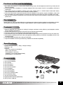
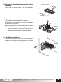
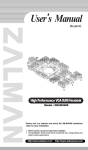
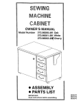
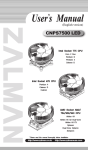
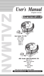
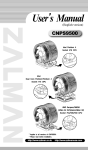
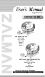
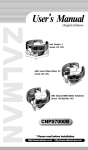
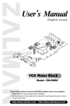
User’
s Manual
(English)
High Performance Fanless VGA Cooler
Model : VNF100
Please visit our website and watch the VNF100 installation video
installation.
※ Please read this manual thoroughly before installation.
※ The specifications of this product and its components may change without prior
notice to improve performance.
http://www.zalman.co.kr
http://www.zalmanusa.com
Cautions on Use and Installation
1. By installing this product on a VGA (Video Graphics Array) card, a PCI slot adjacent to the PCIe (or AGP) slot will
become unusable.
2. If this product will be installed on a recently released VGA card, please check for compatibility at Zalman’s
website first.
3. The product cannot be installed on Matrox VGA cards, NVIDIA PCX 5 , NVIDIA Geforce 6600 AGP Series,
Geforce 7600/7300 AGP Series, and ATI Radeon X700 Pro Series.
4. If the VGA card and its components interfere with the installation of this product, stop the installation, refer to the
list of compatible VGA cards at Zalman’s website and install this product with one of the compatible VGA cards.
5. The use of an exhaust fan positioned on the rear side of the case is recommended for enhancement of product
performance.
Disclaimer
Zalman Tech Co., Ltd. is not responsible for any damages due to external causes, including but not limited to, improper
use, problems with electrical power, accident, neglect, alteration, repair, improper installation, or improper testing.
Features
1. Zalman’s patented VFP (Variable Fin Profile) Fin Design maximizes cooling efficiency and dissipation surface
area for excellent performance.
2. Fanless VNF100 does not emit any noise and can be used semi-permanently.
3. Three high performance heatpipes provide maximized heat transfer.
4. Thin aluminum fins (0.4mm) provide minimized heatsink weight, and prevents excessive force on the VGA card.
5. The heatsink positioned above the VGA card optimizes cooling efficiency and allows compatibility with SLI and
CrossFire setups.
6. VGA RAM Heatsninks allow the cooling of VGA RAM.
7. Improved installation structure provides easy installation and broad compatibility.
Specifications
- Heatsink Dimensions (mm) : 166(L) X 95(W) X 38.5(H)
- Weight (g) : 180
- Materials
Fins : Pure Aluminum (Anodized)
Base : Pure Aluminum
Front Heatsink : Aluminum
Heatpipes : Pure Copper (Nickel-Plated)
RAM Heatsink : Pure Aluminum
Components
① One (1) Rear Heatsink
② One (1) Base
③ One (1) Socket A
④ One (1) Socket B
⑤ One (1) Front Heatsink
⑥ Four (4) Nipples
⑦ Four (4) Fixing Nuts
⑧ Four (4) Fixing Bolts
⑨ One (1) PVC Washer Plate
⑩ Four (4) Rubber Rings
⑪ Two (2) Thermal Grease
⑫ Eight (8) RAM Heatsinks (ZM-RHS2)
⑬ One (1) User’
s Manual
※
①
②
⑥
⑫
③
④
⑦
⑧
⑤
⑨
⑩
⑪
⑬
The specifications of any product may change without prior notice to improve performance.
1
Exploded View
Fixing Bolt
Front Heatsink
Nipple
Socket
Base
Rubber Ring
Ram Heatsink
Rear Heatsink
VGA Chipset
VGA RAM
PVC Washer
Fixing Nut
Logo
※
The specifications of any product may change without prior notice to improve performance.
2
Installation Procedure
※The following installation sequence MUST be followed.
Gre
as
Th
erm
al
RAM
Heatsink
Thermal Tape
Film
erm
al
Gre
as
e
VGA RAM
Th
erm
al
Gr
ea
se
① Remove the Film from the Thermal Tapes on the bottom of
the RAM Heatsinks (ZM-RHS1) and attach the Heatsinks on
the VGA RAM.
Note 1) If Thermal Grease or other residue remains on the RAM,
the Thermal Tapes will not stick. Clean the surface of the
RAM with acetone or alcohol before attaching.
Note 2) The bonding strength of the Thermal Tapes reaches
90% after 24 hours of curing. Do not exert excessive
force on the RAM Heatsinks during this period.
Note 3) Thermal Tapes are not reusable because they lose
adhesiveness after their initial attachment. Purchase
new Thermal Tapes if the RAM Heatsinks need to be
reattached.
Th
1. VGA RAM Heatsink Attachment
e
(VGA RAM Heatsink Attachment
Thermal Grease Application on VGA Chipset
Socket Selection & Nipple
Attachment on Socket Guide Socket Assembly on Base Installation of Base Assembly Assembly of Fixing
Nut on Base Assembly
Thermal Grease Application on Base
Rear Heatsink Installation
Thermal Grease
Application on Front Heatsink Front Heatsink Installation VGA Card Installation)
Clean the contact surface of the VGA Chipset completely. Apply
Thermal Grease on the VGA Chipset that makes contact with
the base of the VGA Cooler.
3. Socket Selection & Nipple Installation on the
Socket Guide
Check the hole locations compatible with Socket A or Socket B
and choose a socket accordingly. Install the Nipples to anticlockwise on the Socket Guide.
※ Please check the table below to identify the correct Nipple
Installation Holes for specific models of VGA cards.
Thermal
Grease
Th
erm
al
Gr
ea
se
2. Thermal Grease Application on VGA Chipset
VGA
Chipset
Nipple
Nipple Installation Holes for
Various VGA Cards
VGA Card
Nipple Installation Holes
❶
❷
❸
❹
❺
ATI X1050 Series
ATI X1300 Series
ATI X1600 Series
ATI Radeon 9*** Series
ATI Radeon X*** Series (except X700 Pro, X850 Series)
NVIDIA Geforce4 MX Series
NVIDIA Geforce FX 5200
NVIDIA Geforce FX 5500
NVIDIA Geforce FX 5600 (FX 5700)
NVIDIA Geforce 6600 Series (except 6600 AGP Series)
NVIDIA Geforce 7300 Series (except 7300 AGP Series)
NVIDIA Geforce4 TI 4 Series
NVIDIA Geforce FX 5700(Ultra) Series
NVIDIA Geforce FX 5800 Series
NVIDIA Geforce 6600 Series (except 6600 AGP Series)
ATI X1300 Series
ATI X1550 Series
ATI X1600 Series
NVIDIA Geforce 8600 Series
NVIDIA Geforce 8500 Series
NVIDIA Geforce 7600 GS Series
NVIDIA Geforce 6600 Series (except 6600 AGP Series)
NVIDIA Geforce FX 5900 Series
NVIDIA Geforce FX 5950 Series
ATI X1800 XL Series
NVIDIA Geforce 7950 Series (except GX2 Series)
NVIDIA Geforce 7900 Series (except GTO, GTX Series)
NVIDIA Geforce 7800 Series (except GS, GTX Series)
NVIDIA Geforce 7600 Series (except 7600 AGP Series)
NVIDIA Geforce 7300 Series (except 7300 AGP Series)
NVIDIA Geforce 6800 Series
※
Socket
3
2
2
2
2
3
1
1
3
3
Socket
Guide
5
5
4
4
4
4
5
5
The specifications of any product may change without prior notice to improve performance.
3
Socket
4. Socket Assembly on Base
Assemble the Base with the Nipple-attached Socket in as
shown in the diagram.
Note 1) Make sure that the Heatpipe Grooves are alignedwhen
assembling the Socket with the Base.
Note 2) If the Base and Socket are not properly assembled, it
may cause the Base to be unbalanced. Make sure that
the Base is properly set into the Socket.
Base
Nipple
Heatpipe
Groove
5. Installation of Base Assembly
Insert the Rubber Rings into the Nipples installed on the
Base Assembly.
Align and insert the Base Assembly’s Nipples into the VGA
Card’s Mounting Holes.
(Note)
Make sure that the Base Assembly is installed so that the
center of the Base Assembly is closely adhered to the center of
the VGA Chipset.
Base
Assembly
Rubber Ring
Nipple
6. Installation of Fixing Nuts on the Base
Assembly
Place a PVC Washer over each Nipple installed on the rear
side of the VGA card.
Slightly screw each of the four Spring-attached Fixing Nuts
onto each Nipple, then tighten each Fixing Nut one rotation
at a time until all are completely tightened.
Note 1) Make sure that the VGA Chipset and Base Assembly
do not get disconnected while simultaneously flipping
the Base Assembly and VGA Card.
Note 2) Fully tightening one Fixing Nut at a time may result in
damaging the VGA Chipset. Please tighten each
Fixing Nut one rotation at a time until all are completely
tightened.
Rubber
Ring
Mounting
Hole
Fixing Nut
PVC Washer
7. Thermal Grease Application on the Base
Evenly apply the Thermal Grease on the Heatpipe Grooves of
the Base.
Thermal Grease
Heatpipe
Groove
8. Rear Heatsink Installation
Insert the Rear Heatsink in the direction of the slot (in the
direction of the arrow) from the VGA Card’s center as
shown on the diagram.
Insert the Rear Heatsink so that the Heatpipe’s straight line
section is closely adhered to the Base’s Heatpipe Grooves.
Note 1) Make sure that the Heatpipes do not come in contact
with the side of the VGA Card when connecting the
Rear Heatsink with the VGA Card. Heatpipe must be
distanced by at least 3 mm from the PCB side.
Heatpipe
Groove
Note 2) Make sure that the Heatsink Fins do not come in
contact with the rear side of the VGA Card or with other
components when connecting the Rear Heatsink with
the VGA Card.
Rear Heatsink
※
The specifications of any product may change without prior notice to improve performance.
4
9. Thermal Grease Application on the Front
Heatsink
Thermal Grease
al
erm
Th
ase
Gre
al
erm
Th
Heatpipe
Groove
Front
Heatsink
Gr
ea
se
Th
erm
al
Gre
as
e
Evenly apply the Thermal Grease on the Front Heatsink’s
Heatpipe Grooves.
10. Front Heatsink Installation
Place the Front Heatsink above the Heatpipes.
Assemble the Base Assembly and the Front Heatsink
with the four Fixing Bolts.
(Note) Fully tightening one Fixing Bolt at a time may cause
the Front Heatsink to tilt, preventing optimal contact
with the Heatpipes, and lead to a decrease in
performance. Please tighten each Fixing Bolt one
rotation at a time until all are completely tightened.
Fixing Bolt
Front
Heatsink
11. VGA Card Installation
Insert the assembled VGA Card into the motherboard’s
PCIe (or AGP) slot. Use the Fixing Bolt to secure the VGA
Card onto the computer case. If the VGA Card has a power
connector on it, remember to plug in the power cable.
PCI Slot
Fixing Bolt
※
The specifications of any product may change without prior notice to improve performance.
5
Zalman Computer Noise Prevention Systems
When building a noiseless computer, use Zalman’
s Ultra Quiet CPU Cooler, Noiseless Power Supply, Heatpipe
HDD Cooler, Fanless Northbridge Cooler and Noiseless Case Fan for more stable performance and a noiseless
environment.
Noiseless Power Supply
Heatpipe HDD Cooler
Fanless Northbridge Cooler
Noiseless Case FAN
Ultra Quiet CPU Cooler
Computer Enclosures
GT-1000
High End Gaming Enclosure Built with
Sturdy All Aluminum Panels
Three Tool Free Hinged Magnetic Panels
(2 Left, 1 Right) for Easy Installation and
Assess to Components
Tool Free Installation of Disk Drives (HDD,
ODD, FDD), Fan Controllers, Audio
Interfaces etc.
Accommodates up to 6 Hard Drives (4 in
the HDD Chassis, 2 on the Bottom Panel)
Luxurious and Cool Aesthetics
Color Options : Black (Red LED Fans),
Titanium (Blue LED Fans)
Home Theatre PC Enclosures
The HD160XT is designed for ultra quiet home theatre
PC operation, utilizing optimized ventilation and
anti-vibration reinforcements, making it ideal for
environments that require silence such as living
rooms, bedrooms, educational facilities, and offices.
For more information, please visit our website.
HD160XT
※
The specifications of any product may change without prior notice to improve performance.
6