1
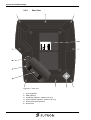
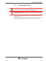
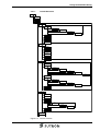
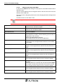
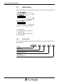
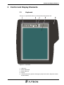
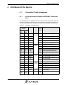
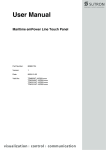
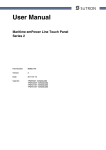
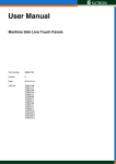
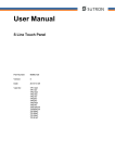
User Manual
Mobile Line Touch Panel HTP105XiT
Part Number:
80860.760
Version:
3
Date:
2012-01-31
Valid for:
HTP105XiT
Version
1
2
3
Date
2010-03-16
2011-01-13
2012-01-30
Modifications
First Edition
Technical data updated
Standards updated, Added pin / cable assignment.
This manual, including all illustrations contained herein, is copyright protected. Use of this manual by any third
party in departure from the copyright provision is forbidden. No part of this manual may be reproduced, translated or electronically or photographically archived or altered without the express written consent from Sütron
electronic GmbH. Violations shall be cause for damage liability.
Sütron electronic reserves the right to make any changes that contribute to technical improvement.
Overall Table of Contents
Overall Table of Contents
1
Important Notes ....................................................................................................... 1-1
1.1
Symbols .................................................................................................... 1-1
1.2
Safety Notes ............................................................................................. 1-1
1.3
Intended Use ............................................................................................ 1-2
1.4
Target Group ............................................................................................ 1-2
2
Design and Commissioning ..................................................................................... 2-1
2.1
Unpacking the Device............................................................................... 2-1
2.2
Design....................................................................................................... 2-2
2.2.1
Front View with Dimensions ................................................................ 2-2
2.2.2
Side View with Dimensions ................................................................. 2-3
2.2.3
Rear View ............................................................................................ 2-4
2.3
Connecting the Device.............................................................................. 2-5
2.4
Switching On............................................................................................. 2-6
2.4.1
Loading Procedure on Windows CE Operating System ...................... 2-6
2.4.1.1
Launch Structure ........................................................................................................2-7
2.4.1.2
Normal Mode ..............................................................................................................2-8
2.4.1.3
Setup Main Mode........................................................................................................2-8
2.4.1.4
Administration Operating Mode ................................................................................2-18
2.5
2.5.1
Identification............................................................................................ 2-20
Version Key ....................................................................................... 2-20
3
Control and Display Elements ................................................................................. 3-1
3.1
Keyboard .................................................................................................. 3-1
3.1.1
Help Keys ............................................................................................ 3-2
3.2
Touch Screen ........................................................................................... 3-2
3.3
Stop Push-button / Emergency Stop Push-button .................................... 3-3
3.4
Consent Switch......................................................................................... 3-4
3.5
Display ...................................................................................................... 3-4
4
Interfaces of the Device ........................................................................................... 4-1
4.1
Connector / Cable Assignment ................................................................. 4-1
4.1.1
22 pin connector for Siemens PROFINET Connection Box ................ 4-1
4.1.2
19 pin device connector with open cable end...................................... 4-2
5
Maintenance and Servicing ..................................................................................... 5-1
5.1
Maintenance Interval ................................................................................ 5-1
5.2
Front Panel ............................................................................................... 5-1
5.3
Fuse.......................................................................................................... 5-1
5.4
Battery (Option) ........................................................................................ 5-1
i
Overall Table of Contents
5.4.1
Battery Disposal................................................................................... 5-2
6
Technical Data .........................................................................................................6-1
6.1
General ..................................................................................................... 6-1
6.2
Options...................................................................................................... 6-4
7
Ordering Data...........................................................................................................7-1
A
Index ....................................................................................................................... A-1
ii
Important Notes
1
Important Notes
1.1
Symbols
The symbols in this manual are used to draw your attention on notes and dangers.
This is the safety alert symbol. It is used to alert you to potential personal injury hazards. Obey all safety messages that follow this symbol to avoid possible injury or
death.
DANGER
This indicates a hazardous situation which, if not avoided, will result in death or serious injury.
WARNING
This indicates a hazardous situation which, if not avoided, could result in death or serious injury.
CAUTION
This indicates a hazardous situation which, if not avoided, could result in minor or
moderate injury.
NOTICE
This symbol together with the signal word NOTE and the accompanying text alert the
reader to a situation which may cause damage or malfunction to the device, hardware/software, or surrounding property.
Reference to source of information
This symbol and the accompanying text provide the reader with additional information or refer to detailed sources of information.
1.2
Safety Notes
–
Read this manual carefully before using the operating device. Keep this manual
in a place where it is always accessible to all users.
–
Proper transportation, handling and storage, placement and installation of this
product are prerequisites for its subsequent flawless and safe operation.
–
This user manual contains the most important information for the safe operation
of the device.
–
The user manual, in particular the safety notes, must be observed by all personnel working with the device.
–
Observe the accident prevention rules and regulations that apply to the operating
site.
–
Installation and operation must only be carried out by qualified and trained personnel.
1-1
Important Notes
1.3
Intended Use
–
The device is designed for use in the industry.
–
The device is state-of-the art and has been built to the latest standard safety requirements. However, dangerous situations or damage to the machine itself or
other property can arise from the use of this device.
–
The device fulfills the requirements of the EMC directives and harmonized European standards. Any modifications to the system can influence the EMC behavior.
NOTICE: Radio Interference
This is a class A device. This device may cause radio interference in residential areas. In this case, the user may be required to introduce appropriate countermeasures, and to bear the cost of same.
1.4
Target Group
The use of products described in this manual is oriented exclusively to:
1-2
–
Qualified electricians or persons instructed by them, who are familiar with applicable standards and other regulations regarding electrical engineering and, in
particular, the relevant safety concepts.
–
Qualified application programmers and software engineers, who are familiar with
the safety concepts of automation technology and applicable standards.
Design and Commissioning
2
Design and Commissioning
2.1
Unpacking the Device
Unpack all parts carefully and check the contents for any visible damage in transit.
Also check whether the shipment matches the specifications on your delivery note.
If you notice damages in transit or discrepancies, please contact our sales department immediately.
2-1
Design and Commissioning
2-2
2.2
Design
2.2.1
Front View with Dimensions
Figure 2-1
Front view with dimensions
Design and Commissioning
2.2.2
Side View with Dimensions
Figure 2-2
Side View with Dimensions
2-3
Design and Commissioning
2-4
2.2.3
Rear View
Figure 2-3
Rear view
1
Housing Screws
2
USB (optional)
3
Handle Set (optional - position can vary)
4
Consent Switch (optional - position can vary)
5
Device Connector (optional)
6
Name Plate
Design and Commissioning
2.3
Connecting the Device
WARNING: Risk of electric shock
Hazardous voltages can exist inside electrical installations that can pose a danger to
humans. There is a risk of electric shock when touching live parts!
For information on the pin or core numbers for the supply voltage, please refer to the
chapter "Device Interfaces".
The device is protected against polarity reversal. The device will not operate if the
polarity is incorrect.
This device is in Protection Class I. To ensure safe operation, a safety extra-low voltage (SELV) according to DIN EN 61131 must be used for the supply voltage.
2-5
Design and Commissioning
2.4
Switching On
The Windows CE operating system is installed on the operating device. Running on
the operating system is the visualization runtime.
2.4.1
Loading Procedure on Windows CE Operating System
The program allows you to use the buttons to make changes to the configuration.
The operating device has 3 operating modes:
–
2-6
Normal (no button is pressed)
–
Setup Main (Button Press For Setup Main Menu was pressed)
–
Administration (Admin button was pressed)
Design and Commissioning
2.4.1.1
Launch Structure
Start
Normal
Admin
Setup-Main
Update
Copy USB Stick
Copy to Flash
Copy to USB
Import Settings
Home
Update Image
Update
Bootloader
Install Fonts
Home
TouchScreen
& Registry
Save Registry
Settings
Change
Display Mode
Start Calibration
Backlight
Properties
SNTP Settings
Home
Network
Settings
TCP/IP Info
Fix Settings
IP Address
Gateway
DNS
WINS
Home
DHCP
FTP Settings
Add new user
List all users
Delete a user
Home
Device Name
Home
Settings
Contrast
Date / Time
Password
Printer
Page
Settings
Network
Print
Home
Information
Home
Start Batchfile
Exit
Figure 2-4
Launch structure
2-7
Design and Commissioning
2.4.1.2
Normal Mode
The program AppStarter.exe starts from the internal Flash memory.
Admin
Press For Setup Main Menu
Figure 2-5
Display after startup
Please, note that the device is accessible over the Ethernet only after assignment
of an IP address to the Ethernet.
2.4.1.3
Setup Main Mode
If you press the Press For Setup Main Menu button during the startup phase, the
"Setup Main" mode starts.
Setup Main
Update
Exit
Touch Screen
& Registry
Settings
Network
Settings
Start
Batchfile
Figure 2-6
Setup Main
Some settings are password-protected. The default password is "+-+-".
Update:
Update
Copy USB
Stick
Home
Update Image
Update
Bootloader
Figure 2-7
Install Fonts
Update
Update, Copy USB-Stick:
Copy USB Stick
Copy to Flash
Home
Copy to USB
Import
Settings
Figure 2-8
2-8
Copy USB Stick
Design and Commissioning
Update, Copy USB-Stick, Copy to Flash:
This function copies the data from the USB stick to the internal flash file system.
Several projects can be managed in subdirectories below the directory TSvisRT. If
more than one project is in different subdirectories, a choice dialog is displayed. Only
directories which contain a project file (*.cb) are listed.
The entire TSvisRT directory or the corresponding subdirectory and the
AppStarter.exe are copied into the target directory of the flash file system.
Update, Copy USB Stick, Copy to USB:
Copies the content of the flash file system to the „backup“ directory of the USB stick.
This excludes protected system files. A log file is also transferred, which can be used
to restore system settings via the „Import Settings“ item.
Update, Copy USB Stick, Import Settings:
An automatically generated log file can be used to restore the system settings. If the
„backup“ directory of the USB stick contains a corresponding log file, these settings
can be restored.
This is possible only when using identical device types.
Update, Update Image:
If the „image“ subdirectory on the USB stick contains a „*.nb0“ file, this file is used to
perform the image update. There must only be one „*.nb0“ file in this directory.
In this case, the flash registry is always deactivated so that the image is processed
with a new default registry.
Update, Update Bootloader:
If the „bootloader“ subdirectory on the USB stick contains a „*.nb0“ file, this file is
used to perform the bootloader update. There must only be one „*.nb0“ file in this directory.
The user is informed that the update has been successfully completed.
Update, Install Fonts:
If one or multiple fonts are in the subfolder "Fonts" of the flash memory, these will be
installed at the start-up of the operating device automatically.
Depending on the number and size of fonts, the system start-up take correspondingly
more time.
Touch Screen & Registry:
Touch Screen & Registry
Save Registry
Settings
Home
Change
Display Mode
Backlight
Properties
Start
Calibration
SNTP
Settings
Figure 2-9
Touch Screen & Registry
Touch Screen & Registry, Save Registry Settings:
The entire registry is saved.
2-9
Design and Commissioning
Touch Screen & Registry, Change Display Mode:
Change Display Mode
Current Mode
Cancel
A
A
OK
A
LCD Saver
A
Figure 2-10
Change Display Mode
Set-up of display adjustment.
LCD Saver switches the brightness to the lowest value, if no user operation occures
for at least one hour.
This entry is able to be password-protected.
Touch Screen & Registry, Start Calibration:
The touch calibration is started. After the calibration the values are stored automatically in the registry.
Touch Screen & Registry, Backlight Properties:
Backlight
Timeout in minutes:
Use Screensaver
1
Dim Backlight
2
Switch off Backlight
3
OK
Figure 2-11
Apply
Cancel
Backlight Properties
A screen saver can be activated after the defined time (minutes). It is possible to adjust the screen saver graphic by replacing the file "Screensaver.bmp" in the internal
memory. The graphic is replaced at the start up of the operating device automatically
when a USB stick - containing the file (Screensaver.bmp) in the "Screensaver" directory - is present.
The brightness of the backlight (dim backlight) can be reduced after the defined time
(minutes) and turned off (backlight switch off) in addition.
This entry is able to be password-protected.
2-10
Design and Commissioning
Touch Screen & Registry, SNTP Settings:
SNTP Settings
Time Synchronization
No
SNTPSNTP
Client
Server
SNTPServer
myserver.myhost.local
Interval [minutes]
5
OK
Cancel
Figure 2-12
SNTP Settings
If you activate the "SNTP-Client" option, you can enter the address of a time server
located in the intranet or Internet. The synchronization interval is specified in minutes.
With the option "No SNTP" the synchronization is deactivated.
The operating device may be used as a time server for other devices if the "SNTPServer" option is active.
This entry is able to be password-protected.
Network Settings:
Network Settings
TCP/IP Info
Home
Fix Settings
FTP Settings
DHCP
Device Name
Figure 2-13
Network Settings
All addresses of the Network Settings have to be entered in the format
"xxx.xxx.xxx.xxx".
Numbers smaller than 100 have to be filled up with leading zeros.
(e.g.: 192.168.42.1 -> 192.168.042.001)
Network Settings, TCP/IP Info:
TCP/IP Info
MAC: 0-7-93-FF-FF-CE
IP: 192.168.100.82
Mask: 255.255.255.0
Device Name: MyName
DHCP enabled
Gate: 000.000.000.000
1. DNS: 000.000.000.000
2. DNS: 000.000.000.000
1. WINS: 000.000.000.000
2. WINS: 000.000.000.000
Figure 2-14
OK
TCP/IP Info
The following informations are displayed:
–
MAC address
–
IP address,
–
Subnet mask address,
–
Device name,
–
DHCP status,
–
Gateway address,
–
1. DNS address,
2-11
Design and Commissioning
–
2. DNS address,
–
1. WINS address,
–
2. WINS address.
Network Settings, Fix Settings, IP Address:
IP Address
IP Address
000.000.000.000
Subnet Mask
000.000.000.000
OK
Figure 2-15
Cancel
IP Address
The system automatically deselects DHCP and optionally enters the settings from
the IPSetting.ini file of the USB stick. This file must exist in the root directory of the
USB stick.
If no USB stick is connected the information is read from the registry.
This entry is able to be password-protected.
Contents of the IPSetting.ini file:
[IPCONFIG]
IPAddress=172.016.042.150
SubnetMask=255.255.255.000
Network Settings, Fix Settings, Gateway:
Gateway
Change Default Gateway
000.000.000.000
OK
Figure 2-16
Cancel
Gateway
The system automatically deselects DHCP and optionally enters the settings from
the IPSetting.ini file of the USB stick. This file must exist in the root directory of the
USB stick.
If no USB stick is connected the information is read from the registry.
This entry is able to be password-protected.
Contents of the IPSetting.ini file:
[IPCONFIG]
Gateway=172.016.042.150
2-12
Design and Commissioning
Network Settings, Fix Settings, DNS:
DNS
Primary DNS
000.000.000.000
Secondary DNS
000.000.000.000
OK
Cancel
Figure 2-17
DNS
The system deselects DHCP and enters the settings from the IPSetting.ini file of the
USB stick. This file must exist in the root directory of the USB stick.
If no USB stick is connected the information is read from the registry.
This entry is able to be password-protected.
Contents of the IPSetting.ini file:
[IPCONFIG]
PrimaryDNS=172.016.042.150
SecondaryDNS=172.016.042.151
Network Settings, Fix Settings, WINS:
WINS
Primary WINS
000.000.000.000
Secondary WINS
000.000.000.000
OK
Figure 2-18
Cancel
WINS
The system automatically deselects DHCP and optionally enters the settings from
the IPSetting.ini file of the USB stick. This file must exist in the root directory of the
USB stick.
If no USB stick is connected the information is read from the registry.
This entry is able to be password-protected.
Contents of the IPSetting.ini file:
[IPCONFIG]
PrimaryWINS=172.016.042.150
SecondaryWINS=172.016.042.151
Network Settings, DHCP:
DHCP
DHCP enabled
Save registry and restart device to
work with new parameters
OK
Figure 2-19
DHCP
You may enable DHCP service. You must save this setting when exiting of by using
„Save Registry Settings“.
This entry is able to be password-protected.
2-13
Design and Commissioning
Network Settings, FTP Settings, Add new user:
Add new user
Enter User
MyName
Enter Password
****
Confirm Password
****
OK
Cancel
Figure 2-20
Add new user
You may enter a new user name. You have to assign a password to the user name
and to confirm it.
If at least one user name is added you cannot login to the FTP server as anonymous
anymore.
Network Settings, FTP Settings, List all users:
All users are listed within a DOS box.
Network Settings, FTP Settings, Delete a user:
Delete a user
Enter User
MyName
Enter Password
****
Confirm Password
****
OK
Figure 2-21
Cancel
Delete a user
You may enter the user name you like to delete.
This entry is able to be password-protected.
Network Settings, Device Name:
Device name
Enter Device Name
MyDeviceName
OK
Figure 2-22
Cancel
Device Name
You can define a device name with up to 14 characters. Via a FTP connection you
can access the device with the device name instead of the IP address.
This entry is able to be password-protected.
Settings:
Settings
Contrast
Home
Date / Time
Printer
Password
Information
Figure 2-23
2-14
Settings
Design and Commissioning
Settings, Contrast:
Contrast
Contrast
Brightness
15
15
Color Depth
8 bpp
16 bpp
OK
Figure 2-24
Apply
Cancel
Contrast
The operating mode setup main is displayed with default values for contrast and
brightness to ensure reading also at faulty values. If you change a value, you have
to confirm this in a dialog. If you press Cancel or 5 seconds pass without any action
the value is not accepted.
Depending on the display type different values can be influenced:
Table 2-1
Display Type
Contrast
Brightness
STN (mono)
X
-
STN (color)
X
X
TFT
-
X
Selection of color depth for TFT displays.
This entry is able to be password-protected.
Settings, Date / Time:
Date / Time
Current Time
OK
X
15:00:00 AM
Time Zone
(GMT +01:00) Amsterdam, Berlin, Bern, Rome
Automatically adjust clock for daylight saving
Apply
Figure 2-25
Date / Time
Set the date, time and time zone.
2-15
Design and Commissioning
Settings, Password:
Password
Current Password
Enable Password
Change
OK
Figure 2-26
Cancel
Password
The password can be activated, deactivated or redefined. When the password is activated, all password-protected dialog boxes can only be accessed if the password
has been entered successfully.
This entry is able to be password-protected.
Settings, Printer:
Printer
Page
Settings
Network
Print
Home
Figure 2-27
Printer
The print function depends on the application program on the operating device. Connection of a printer is possible via the network and the USB interface. The operating
system supports PCL3-compatible printers.
Table 2-2
Already used printer models
Model
HP OfficeJet 6000
HP OfficeJet Pro 8000
HP DeskJet 6940
HP DeskJet 5150
HP Laserjet 1505N
This entry is able to be password-protected.
Settings, Printer, Page Settings:
Page Settings
Page Settings:
Letter
A4
OK
Figure 2-28
Cancel
Page Settings
Select the paper format, "Letter" or "A4", "Letter" is default.
This entry is automatically stored in the registry.
2-16
Design and Commissioning
Settings, Printer, Network Print:
Network Print
Network Printer Path:
Network Server Login
OK
Cancel
Figure 2-29
Network Print
Enter the network printer path.
This entry is automatically stored in the registry.
Settings, Printer, Network Print, Network Server Login:
Network Server Login
User Name:
Password:
Domain:
OK
Cancel
Figure 2-30
Network Server Login
You may perform a network login.
Enter a user name, password and domain.
This entry is automatically stored in the registry.
Settings, Information:
Information
SNR: 1023456789
Image_Grafikpanel_EP9307_CE5.00_
V1.18
Built: Aug 27 2007 14:00:00
Flash Size: 16 MB
SRAM Size: 512 kB
PLC / VISU RAM: 0 / 460 kB
Busclock: 49 MHz
Click OK to go back to main
Figure 2-31
Information
The following informations are displayed:
–
Serial number,
–
Product ID,
–
Image version,
–
Built version,
–
Built date,
–
Size of flash,
–
Size of SRAM,
–
Size of PLC / Visu RAM,
–
Bus clock speed.
Start Batchfile:
The project.bat file in the FlashDrv directory starts, if available.
2-17
Design and Commissioning
2.4.1.4
Administration Operating Mode
If you press the Admin button during the startup phase, the Administration mode of
operation starts.
You can use the Admin.ini file to manage the device. This file must exist in the root
directory of the USB stick.
This file is used as a dongle to prevent users from changing the device during normal
operation.
Possible contents for the Admin.ini file:
Observe upper and lower case for all entries!
Explorer=Off
Deactivates the Explorer in the registry. The change becomes
effective on the next device reboot.
Explorer=On
Activates the Explorer in the registry. The change becomes effective on the next device reboot.
Start=explorer.exe
Starts the explorer
Start=MyProgram.exe
Starts the application MyProgram.exe
Initial directory is windows. Use the following syntax to start an
application on the usb stick:
Start=\\\\HardDisk\\MyProgram.exe
Use multiple entries to start several applications.
Registry=Default
Destroys the current registry and activates the default registry
of the image. The change becomes effective on the next device reboot.
StartRepllog=On
Enables automatic startup of the Repllog.exe program in the
registry. The change becomes effective on the next device reboot.
StartRepllog=Off
Disables automatic startup of the Repllog.exe program in the
registry. The change becomes effective on the next device reboot.
LaunchTouch=On
The touch variant of the launch will start at devices with keyboard. The change becomes effective on the next device reboot.
LaunchTouch=Off
The standard variant for the device will start.
The change becomes effective on the next device reboot.
Lock=On
The buttons Press for Setup Main Menu and Admin are
disabled.
If the file „Admin.ini“ is found on the usb stick the button Admin
is enabled. Therefore the deactivation of the lock is possible.
The change becomes effective on the next device reboot.
Lock=Off
All buttons enabled.
The change becomes effective on the next device reboot.
Mode=Development
The shell has full functionality.
The change becomes effective on the next device reboot.
2-18
Design and Commissioning
Mode=Standard
The Shell is restricted: No task bar and task switch available.
Desktop contains the launch icon only.
The change becomes effective on the next device reboot.
DeviceName=MyName
Defines the device name of the operating device
;DeviceName=MyName
Comment, no impact
2-19
Design and Commissioning
2.5
Identification
The operating device can be identified using the nameplate on the rear of the device.
Figure 2-32
Nameplate (example)
1
Order number
2
Version key (at time of delivery)
3
MAC address
4
Voltage and power specification
5
Serial number
2.5.1
Version Key
The version key provides information on the version level of various components at
time of delivery.
80850430
Bundle
Bootloader
Image
Application Software
Installation /
Auxiliary Software
2-20
_
113
.
118
.
04XX
.
101
Control and Display Elements
3
Control and Display Elements
3.1
Keyboard
The keys are positioned under an environmental-proof polyester foil.
Figure 3-1
Front view
1
Help Keys
2
Status LED Mode
3
Status LED Info
4
Display
5
Command Devices (optional: Emergency Stop Push-button, Stop Push-button,
Keylock Switch)
3-1
Control and Display Elements
3.1.1
Help Keys
Use this key to show a soft keyboard. To hide the keyboard, press the key again.
Use this key to open the Task Manager in order to change to another task or use this
key to close the Task Manager. When you press this key again, the dialog for changing to another task is closed.
Use this key to open the Service tool. To exit the Service tool, press the key again.
Use this key to open the context menu, which can usually be reached by pressing
the right mouse button.
To define the contrast / brightness setting, use the key combinations shown below
as follows:
To increase the contrast:
To increase the
brightness:
To reduce the contrast:
To reduce the brightness:
3.2
Touch Screen
The device is equipped with a resistive 4 wire touch screen. You operate the device
using this touch screen.
NOTICE: Damage
Pointed or sharp objects, such as pens or fingernails, can lead to irreparable damages of the touch screen. Exclusively therefore use the fingertips or the aids indicated
in the technical data for the operation.
NOTICE: Damage
To protect the touch screen you can use special protection foils. You receive corresponding protection foils directly from Sütron electronic.
3-2
Control and Display Elements
3.3
Stop Push-button / Emergency Stop Push-button
The device can be fitted with an optional stop push-button or an emergency stop
push-button.
The operating device has to be regarded as a component of the integrated plant
merely. Take suitable protective measures in accordance with the requirements of
your plant therefor.
The STOP push-button on the operating device ensures that the system to be monitored is shut down safely in accordance with EN 60204-1:2006. The stop function
can be a Category 0, 1 or 2 stop according to EN 60204-1:2006 and must be defined
according to the risk assessment.
Therefore, the stop function of the operating device can be used for a safe machine
stop as well as for looping into the emergency stop circuit of the system to be monitored.
WARNING
If using a hand-held operating device with an emergency stop button, you must ensure that the connecting cable is securely installed.
A hand-held operating device that is not connected to the machine must be stored
out of sight of the user!
Bear in mind that the nearest emergency stop will be activated in the event of danger.
If it does not work because it is not connected, this could have fatal consequences!
WARNING
If the hand-held operating device is equipped with a STOP push-button but it is not
connected to the linkbox, a stop can not be triggered using the hand-held operating
device – the STOP push-button of the hand-held operating device is ineffective!
Install stationary emergency stop buttons that are available at all times on the system
to be monitored.
WARNING
If the stop circuit has been implemented as a Category 0 or 1 stop, the stop function
must be effective regardless of the operating mode. A Category 0 stop must have priority. The releasing of the STOP push-button must NOT lead to hazardous conditions
(also see EN 60204-1:2006).
The stop function is not a substitute for safety devices.
3-3
Control and Display Elements
3.4
Consent Switch
The device is fitted with a handle set featuring an integrated 3-step consent switch.
Operating sequences can only be performed if the 3-step switch is actuated while set
to its middle position. The stop signal is issued when the switch is set to its upper and
lower position. After a stop in the lowest position, the release command can only be
issued if the switch is fully released and pushed to the middle position again.
The operating device has to be regarded as a component of the integrated plant
merely. Take suitable protective measures in accordance with the requirements of
your plant therefor.
The use of a 2-circuit design for the consent equipment enables compliance with
safety category 3 PL d according to EN ISO 13849-1 and the suitable monitoring on
short circuit and cross circuit of these circuits.
EN 60204 describes the mode of operation of the consent equipment. Based on information gathered from accident research and on the technical solutions currently
available, the 3-step consent switch represents state-of-the-art technology. Positions
1 and 3 of the consent switch are "OFF" functions. Only the middle position activates
consent.
The stop category of the consent equipment must be selected on the basis of a risk
assessment and must correspond to a Category 0 or Category 1 stop.
WARNING
The consent switch is only suitable for use as a protection function if the person operating the consent switch is able to recognize hazards to personnel in good time and
can then immediately initiate hazard prevention measures!
Slower movement speed may also be necessary as an additional measure. The permissible speed must be determined on the basis of a risk assessment.
WARNING
No commands related to hazardous conditions may be initiated by the consent
switch alone. A second, conscious start command is necessary (button on hand-held
operating device). Only the person operating the consent switch is permitted to be
present in the hazardous area.
The following standards must be applied for the risk analysis to be carried out:
•
EN 12100-1 and EN 12100-2 „Safety of machinery - basic concepts, general
principles for design“
•
EN 14121-1 „Safety of machinery - risk assessment“
3.5
Display
DANGER: Toxic
If the display is damaged, avoid touching, swallowing or breathing in the liquids or
gases which may leak out!
DANGER: Corrosive
If the display is damaged, avoid touching, swallowing or breathing in the liquids or
gases which may leak out!
The operating device is equipped with a TFT display.
3-4
Interfaces of the Device
4
Interfaces of the Device
4.1
Connector / Cable Assignment
4.1.1
22 pin connector for Siemens PROFINET Connection
Box
The operating device is equipped with an assembled 19 pin device connector at the
enclosure. This device connector gets connected to the connector cable which has
a 22 pin male connector for connection to a Siemens PROFINET connection box.
Table 4-1
Connector / cable assignment
Pin at Connector
Wire
ø mm²
Designation
Function
5x
0.155
+
24 V
Supply Voltage 24 VDC
22
Pin
19
Pin
14
2
BK
6
11
GRPK
S
Consent Switch Channel 1
5
10
BNGN
S
Consent Switch Channel 1
4
18
WHGN
S
Consent Switch Channel 2
7
17
RDBU
S
Consent Switch Channel 2
12
1
VT
11
9
GN
10
16
9
5x
0.155
0V
Supply Voltage 0 VDC
Ö
Stop Push-button Channel 1
BN
Ö
Stop Push-button Channel 1
7
YE
Ö
Stop Push-button Channel 2
8
8
GR
Ö
Stop Push-button Channel 2
15
-
BU
-
Not Connected
22
-
BUWH
-
Not Connected
-
-
PK
-
Not Connected
-
-
PKWH
-
Not Connected
18
3
WH
19
4
OR
17
5
16
4x
0.155
4x
0.155
Tx+
Ethernet
Tx-
Ethernet
WH
Rx+
Ethernet
6
GN
Rx-
Ethernet
20
12
Shield
-
Enclo
sure
Enclo
sure
Shield
-
-
RJ45 Shield
Low-Noise Ground
4-1
Interfaces of the Device
4.1.2
19 pin device connector with open cable end
The operating device is equipped with an assembled 19 pin device connector at the
enclosure. This device connector gets connected to the connector cable which has
an open cable end.
Table 4-2
4-2
Connector / cable assignment
Pin
Wire
ø mm²
Designation
Function
1
GN
5 x 0,34
0V
Supply Voltage 0 VDC
2
BN
+
24 V
Supply Voltage 24 VDC
12
YE
15
GR
S
Key Switch (optional)
19
WH
S
Key Switch (optional)
9
RD
Ö
Stop Push-button Channel 1 (optional)
16
PK
Ö
Stop Push-button Channel 1 (optional)
7
BU
Ö
Stop Push-button Channel 2 (optional)
8
BK
Ö
Stop Push-button Channel 2 (optional)
10
WHGN
S
Consent Switch Channel 1
11
VT
S
Consent Switch Channel 1
17
GRPK
S
Consent Switch Channel 2
18
RDBU
S
Consent Switch Channel 2
3
YE
4
Low-Noise Ground
4 x 0,34
4 x 0,34
4 x 0,15
Tx+
Ethernet
GN
Tx-
Ethernet
5
PK
Rx+
Ethernet
6
BU
Rx-
Ethernet
Maintenance and Servicing
5
Maintenance and Servicing
5.1
Maintenance Interval
The following maintenance intervals are recommended for this operating device:
Table 5-1
Maintenance interval
Maintenance work
Interval
Changing the Battery
4 Years
5.2
Front Panel
Only use a damp cloth to remove any dirt from the front panel.
5.3
Fuse
NOTICE: Damage
The semiconductor fuse cannot be replaced!
A semiconductor fuse is used to protect the device. Once the fuse has been tripped,
the device must be disconnected from the supply voltage to allow the semiconductor
fuse to regenerate. At an ambient temperature of 20 °C (68 °F), the regeneration
takes approximately 20 seconds. The higher the ambient temperature, the longer the
regeneration takes.
5.4
Battery (Option)
The built-in battery supplies the real-time clock. The minimum battery life is 5 years,
even under unfavorable operating conditions.
We recommend to change the battery approximately every 4 years by the service of
Sütron electronic as part of the regular maintenance work.
Carry out the following to check the battery status:
1. Press the Servicetool button on your operating device.
2. Open Systeminfo by double-clicking (double-tapping) the appropriate icon.
3. Select the Battery tab.
You can display the following statuses:
Battery OK
Battery is ready for operation
No battery found
Battery is empty or there is no
battery at all
5-1
Maintenance and Servicing
5.4.1
Battery Disposal
The manufacturer is obliged to mark batteries with this symbol before first placing
into market. The symbol is extended by the chemical symbols if the following limiting
values are exceeded:
More than 0.0005 mass percent mercury
Hg
More than 0.002 mass percent cadmium
Cd
More than 0.004 mass percent lead
Pb
Batteries can be given back free of charge after use at the place of purchase.
According to the §11 of the battery law, final consumers are obligedly to give old batteries back to gathering points which attached to the common take back system or
manufacturer-specific take back systems.
NOTICE: Damage
To prevent short circuitry in the collection boxes, insulate the poles of each battery
with insulation tape or put each single battery into a plastic bag.
5-2
Technical Data
6
Technical Data
6.1
General
Display
Type
TFT (color)
Resolution (pixels)
800 x 600
Colors
65536
Reading angle (vertical /
horizontal)
110° / 140°
Backlight
CCFL
Half-life backlighting
50,000 h
Brightness in cd/m2
330
Display area (H x W) in
mm (Inch)
158 x 211
(6.22 x 8.307)
Keyboard
Type
Membrane Keyboard
Number of Keys
5 Help Keys
Key Area (Embossment)
12 mm x 12 mm (0.473" x 0.473")
Actuator Travel
0.6 mm (0.024")
Activation Power
3N
Switching Cycles
Approx. 3 Million Under the Following Conditions:
Keystroke Element: Testing Ram (DIN 42115)
Keystroke Load: 10 N
Keystroke Frequency: 1 Hz
Display Elements
2 Status LEDs
Touch Screen
Type
Analog resistive, 4 wire technology
Activation force
15 g (Standard)
With R8 HS60 silicon rubber
Durability
No damages or malfunctions after 3 million keystrokes as the following:
Keystroke element: R8, HS40 silicon rubber
Keystroke load: 150 g
Keystroke frequency: 3 Hz
6-1
Technical Data
Electrical Data
Supply voltage
24 V DC (SELV / PELV in accordance with DIN EN 61131)
Residual ripple
10 % maximum
Minimum voltage
18 V
Maximum voltage
30 V
Power consumption (typical at 24 V)
0.7 A
Power consumption (maximum)
1.0 A
Connected load
16.8 W
Fuse
Semiconductor fuse, self-resetting
Protection against
polarity reversal
Integrated
Central Processing Unit
Central Processing Unit
RISC CPU PXA320
Clock frequency
806 MHz
Other features
Real-time clock (accuracy: +/- 200 ppm)
Memory
Flash (Internal)
1 GByte
SDRAM
128 MByte
SRAM
1 MByte
CompactFlash interface for CompactFlash type I and II (internal)
Ethernet
Ethernet
10/100 Base-T
USB
Corresponds to the "Universal serial bus specification Rev. 1.1“
Host (external)
6-2
Min.: 1,5 Mbit/s
Max.: 12 Mbit/s
Max. output current 100 mA per output
Technical Data
Environmental Conditions
Temperature during
operation
0 °C to 50 °C
(32 °F to 122 °F)
Temperature during
storage, transport
- 25 °C to + 70 °C
(- 13 °F to 158 °F)
Relative air humidity for
operation and storage
20 % to 85 %, no condensation
Application area
Degree of pollution 1, overvoltage category II
Standards and Guidelines
Interference Immunity
EN 61000-4-2
EN 61000-4-3
EN 61000-4-4
EN 61000-4-5
EN 61000-4-6
EN 61000-6-2
Emitted Interference
EN 50011 Limit Class Value A
Equipment Requirements
EN 61131
Storage and Transportation
EN 61131 Part 2
Power Supply
EN 61131 Part 2
Electromagnetic Compatibility
2004/108/EG
Degree of Protection
EN 60529
Impact Load, Shocks
EN 60068 Part 2-27
Sinusoidal Vibrations
EN 60068 Part 2-6
Corrosion Protection
IEC 60068
NOTICE: Radio Interference
This is a class A device. This device may cause radio interference in residential areas. In this case, the user may be required to introduce appropriate countermeasures, and to bear the cost of same.
Housing
Type
ROSE Limanda
Material
Polyamide
Impact Resistance
> 7 Nm to DIN 50014
Flammability
V2 to UL94
Degree of Protection
IP65
Total Weight
Approx. 3.2 kg Without Connecting Cable
6-3
Technical Data
6.2
Options
Emergency Stop Push-button
Type
Rafi RAFIX 16
Lifetime
30 000 Switching Cycles
Contact Configuration
Rafi RAFIX 16
Universal Switching Element 2Ö
Switching Element Lifetime
1.000.000
Maximum voltage
24 V AC/DC
Maximum current
1A
Stop Pushbutton
Type
Rafi RAFIX 16
Lifetime
30 000 Switching Cycles
Switching Element
Rafi RAFIX 16
Universal Switching Element 2Ö
Switching Element Lifetime
1.000.000
Maximum voltage
24 V AC/DC
Maximum current
1A
Consent Switch - Jokab
According to EN 60204-1
Type
Jokab Safety JSHD4H2
Switching Element
3-Step Switch (2 Channels)
Mechanical Lifetime
>1 Million Switching Cycles (Upper Position to Middle Position)
>100 000 Switching Cycles (Middle Position to Lower Position)
Maximum voltage
24 V AC/DC
Maximum current
1A
Connection System
Cable Connector (CONINVERS; TU Series), 19 Pin, Bajonett
Device Connector (CONINVERS; TU Series), 19 Pin
Minisnap Male Connector (ODU; B Series), 22 Pin
6-4
Ordering Data
7
Ordering Data
Table 7-1
Accessories
Description
Part No.
USB 2.0 stick 1 GB
81152.100
Protective foil for touch screen 6.5" (Set with 10 protective foils, scraper and instructions)
81251.065
Protective foil for touch screen 10,4" (Set with 10 protective foils, scraper and instructions)
81251.104
Protective foil for touch screen 12,1" (Set with 10 protective foils, scraper and instructions)
81251.121
Protective foil for touch screen 15" (Set with 10 protective foils, scraper and instructions)
81251.150
Connection cable with threaded female connector M23 and Minisnap male connector (5 metres)
88425.050
7-1
Ordering Data
7-2
A Index
A
tem .................................................................... 2-6
Accessories....................................................... 7-1
Administration operating mode ....................... 2-18
M
B
Battery............................................................... 5-1
Battery disposal ................................................ 5-2
C
Connecting........................................................ 2-5
Connector / cable assignment .......................... 4-1
Consent switch.................................................. 3-4
D
Design............................................................... 2-2
Dimensions
Front view ................................................. 2-2
Side view .................................................. 2-3
Display .............................................................. 3-4
E
Emergency stop push-button ............................ 3-3
F
Fuse .................................................................. 5-1
H
Help keys .......................................................... 3-2
I
Identification.................................................... 2-20
Intended use ..................................................... 1-2
K
Maintenance...................................................... 5-1
Maintenance interval ......................................... 5-1
N
Nameplate....................................................... 2-20
Normal mode..................................................... 2-8
O
Ordering data .................................................... 7-1
R
Rear view .......................................................... 2-4
S
Safety notes ...................................................... 1-1
Servicing ........................................................... 5-1
Setup Main operating mode .............................. 2-8
Standards.......................................................... 6-3
Stop push-button............................................... 3-3
Switching on...................................................... 2-6
T
Target group...................................................... 1-2
Technical data................................................... 6-1
Touch screen .................................................... 3-2
U
Unpacking ......................................................... 2-1
V
Version key ..................................................... 2-20
Key
Contrast / brightness................................. 3-2
Hot key...................................................... 3-2
New task ................................................... 3-2
Right mouse button................................... 3-2
Keyboard........................................................... 3-1
L
Launch structure ............................................... 2-7
Loading procedure on windows CE operating sys-
A-1
A-2
SÜTRON electronic GmbH
Kurze Straße 29
D-70794 Filderstadt
Phone: 0049 711 / 77098-0
Fax: 0049 711 / 77098-305
E-Mail: [email protected]
Internet:www.suetron.com