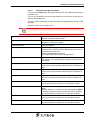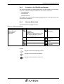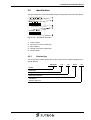
1
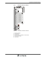
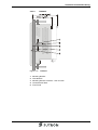
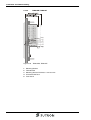
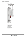
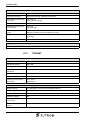
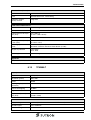
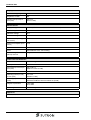
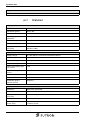
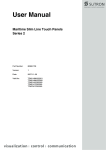
User Manual
Maritime Slim Line Touch Panels
Part Number:
80860.732
Version:
2
Date:
2010-12-01
Valid for:
TPM11AM
TPM11AT
TPM21AM
TPM21AS
TPM21AT
TPM35AM
TPM35AT
TPM43AT
TPM57AM
TPM57AT
TPM70AT
TPM90AT
TPM104AT
TPM105AT
TPM120AT
TPM151AT
Version
1
2
Date
2007-09-14
2010-12-01
Modifications
First Edition
Upgrade devices: TPM35AM, TPM35AT, TPM43AT,
TPM57AM, TPM57AT, TPM90AT, TPM105AT,
TPM120AT, TPM151AT
This manual, including all illustrations contained herein, is copyright protected. Use of this manual by any third
party in departure from the copyright provision is forbidden. No part of this manual may be reproduced, translated or electronically or photographically archived or altered without the express written consent from Sütron
electronic GmbH. Violations shall be cause for damage liability.
Sütron electronic reserves the right to make any changes that contribute to technical improvement.
Overall Table of Contents
Overall Table of Contents
1
2
Important Notes ....................................................................................................... 1-1
1.1
Symbols .................................................................................................... 1-1
1.2
Safety Notes ............................................................................................. 1-1
1.3
Intended Use............................................................................................. 1-2
1.4
Target Group............................................................................................. 1-2
Installation and Commissioning ............................................................................... 2-1
2.1
Unpacking the Device ............................................................................... 2-1
2.2
Mounting the Device ................................................................................. 2-1
2.2.1
Front Panel Dimensions ...................................................................... 2-2
2.2.1.1
TPM11AM, TPM11AT.................................................................................................2-2
2.2.1.2
TPM21AM, TPM21AS, TPM21AT ..............................................................................2-2
2.2.1.3
TPM35AM, TPM35AT.................................................................................................2-3
2.2.1.4
TPM43AT....................................................................................................................2-3
2.2.1.5
TPM57AM, TPM57AT.................................................................................................2-4
2.2.1.6
TPM70AT....................................................................................................................2-5
2.2.1.7
TPM90AT....................................................................................................................2-6
2.2.1.8
TPM104AT..................................................................................................................2-7
2.2.1.9
TPM105AT..................................................................................................................2-8
2.2.1.10
TPM120AT..................................................................................................................2-9
2.2.1.11
TPM151AT................................................................................................................2-10
2.2.2
Mounting Cutout ................................................................................ 2-11
2.2.2.1
TPM11AM, TPM11AT...............................................................................................2-11
2.2.2.2
TPM21AM, TPM21AS, TPM21AT ............................................................................2-12
2.2.2.3
TPM35AM, TPM35AT...............................................................................................2-13
2.2.2.4
TPM43AT..................................................................................................................2-14
2.2.2.5
TPM57AM, TPM57AT...............................................................................................2-15
2.2.2.6
TPM70AT..................................................................................................................2-16
2.2.2.7
TPM90AT..................................................................................................................2-17
2.2.2.8
TPM104AT................................................................................................................2-18
2.2.2.9
TPM105AT................................................................................................................2-19
2.2.2.10
TPM120AT................................................................................................................2-20
2.2.2.11
TPM151AT................................................................................................................2-21
2.2.3
Side View, Mounting Depth ............................................................... 2-22
2.2.3.1
TPM11AM, TPM11AT...............................................................................................2-22
2.2.3.2
TPM21AM, TPM21AS, TPM21AT ............................................................................2-23
2.2.3.3
TPM35AM, TPM35AT...............................................................................................2-24
2.2.3.4
TPM43AT..................................................................................................................2-25
2.2.3.5
TPM57AM, TPM57AT...............................................................................................2-26
2.2.3.6
TPM70AT..................................................................................................................2-27
2.2.3.7
TPM90AT..................................................................................................................2-28
2.2.3.8
TPM104AT................................................................................................................2-29
2.2.3.9
TPM105AT................................................................................................................2-30
2.2.3.10
TPM120AT................................................................................................................2-31
2.2.3.11
TPM151AT................................................................................................................2-32
2.3
2.3.1
Connecting the Device............................................................................ 2-33
Supply Voltage................................................................................... 2-33
i
Overall Table of Contents
2.4
2.4.1
Loading Procedure on Windows CE Operating Procedure................ 2-36
2.4.1.1
Launch Overview...................................................................................................... 2-37
2.4.1.2
Normal Mode ............................................................................................................ 2-38
2.4.1.3
Setup Main Mode ..................................................................................................... 2-38
2.4.1.4
Administration Operating Mode ................................................................................ 2-47
2.4.2
Function of the AppStarter.exe Program ........................................... 2-48
2.4.3
Function of the TSvisLD.exe Program ............................................... 2-49
2.4.4
Memory Media Used .......................................................................... 2-49
2.4.5
Important Files and Update................................................................ 2-50
2.5
2.5.1
3
3.1.1
4.1.1
6
ii
Version Key........................................................................................ 2-51
Display ...................................................................................................... 3-1
Touch Screen....................................................................................... 3-1
Interfaces of the Device ...........................................................................................4-1
4.1
5
Identification ............................................................................................ 2-51
Control and Display Elements ..................................................................................3-1
3.1
4
Switching On ........................................................................................... 2-36
Standard Interfaces................................................................................... 4-1
Ethernet (X5)........................................................................................ 4-2
4.1.1.1
Pin Assignment........................................................................................................... 4-2
4.1.1.2
Cable .......................................................................................................................... 4-2
4.1.1.3
Diagnostics ................................................................................................................. 4-2
4.1.2
USB (X9, X10) ..................................................................................... 4-3
4.1.2.1
Cable .......................................................................................................................... 4-3
Maintenance and Servicing......................................................................................5-1
5.1
Front Panel................................................................................................ 5-1
5.2
Fuse .......................................................................................................... 5-1
5.3
Battery....................................................................................................... 5-1
5.3.1
Changing the Battery ........................................................................... 5-2
5.3.2
Battery Disposal ................................................................................... 5-2
Technical Data .........................................................................................................6-1
6.1
Generally................................................................................................... 6-1
6.2
TPM11AM ................................................................................................. 6-3
6.3
TPM11AT .................................................................................................. 6-4
6.4
TPM21AM ................................................................................................. 6-5
6.5
TPM21AS.................................................................................................. 6-6
6.6
TPM21AT .................................................................................................. 6-7
6.7
TPM35AM ................................................................................................. 6-8
6.8
TPM35AT .................................................................................................. 6-9
6.9
TPM43AT ................................................................................................ 6-11
6.10
TPM57AM ............................................................................................... 6-12
Overall Table of Contents
6.11
TPM57AT................................................................................................ 6-13
6.12
TPM70AT................................................................................................ 6-14
6.13
TPM90AT................................................................................................ 6-15
6.14
TPM104AT.............................................................................................. 6-16
6.15
TPM105AT.............................................................................................. 6-17
6.16
TPM120AT.............................................................................................. 6-19
6.17
TPM151AT.............................................................................................. 6-20
7
Ordering Data .......................................................................................................... 7-1
A
Index ........................................................................................................................A-1
iii
Overall Table of Contents
iv
Important Notes
1
Important Notes
1.1
Symbols
The symbols in this manual are used to draw your attention on notes and dangers.
This is the safety alert symbol. It is used to alert you to potential personal injury hazards. Obey all safety messages that follow this symbol to avoid possible injury or
death.
DANGER
This symbol is used to refer to instructions which, if ignored or not carefully followed,
will result in death or serious injury.
WARNING
This symbol is used to refer to instructions which, if ignored or not carefully followed,
could result in death or serious injury.
CAUTION
This symbol is used to refer to instructions which, if ignored or not carefully followed,
could result in minor or moderate injury.
NOTICE
This symbol and the accompanying text alerts the reader to a situation which may
cause damage or malfunction to the device, either hardware or software, or surrounding property.
Reference to source of information
This symbol refers to detailed sources of information on the current topic.
1.2
Safety Notes
–
Read this manual carefully before using the operating device. Keep this manual
in a place where it is always accessible to all users.
–
Proper transportation, handling and storage, placement and installation of this
product are prerequisites for its subsequent flawless and safe operation.
–
This user manual contains the most important information for the safe operation
of the device.
–
The user manual, in particular the safety notes, must be observed by all personnel working with the device.
–
Observe the accident prevention rules and regulations that apply to the operating
site.
–
Installation and operation must only be carried out by qualified and trained personnel.
1-1
Important Notes
1.3
Intended Use
–
The device is designed for use in maritime areas.
–
The device is state-of-the art and has been built to the latest standard safety requirements. However, dangerous situations or damage to the machine itself or
other property can arise from the use of this device.
–
The device fulfills the requirements of the EMC directives and harmonized European standards. Any modifications to the system can influence the EMC behavior.
NOTICE: Radio Interference
This is a class A device. This device may cause radio interference in residential areas. In this case, the user may be required to introduce appropriate countermeasures, and to bear the cost of same.
1.4
Target Group
All configuration, programming, installation, commissioning, operating and maintenance work in connection with the automation system must be performed by trained
personnel only (e.g. qualified electricians, electrical engineers, etc.).
The configuration and programming personnel must be familiar with the safety concepts of automation technology.
The operating personnel must have been trained in handling the controller and be
familiar with the operating instructions.
The installation, commissioning and maintenance personnel must have an education
which entitles them to work on automation systems.
1-2
Installation and Commissioning
2
Installation and Commissioning
2.1
Unpacking the Device
Unpack all parts carefully and check the contents for any visible damage in transit.
Also check whether the shipment matches the specifications on your delivery note.
If you notice damages in transit or discrepancies, please contact our sales department immediately.
2.2
Mounting the Device
NOTICE: Damage
When installing the device, leave a gap of at least 30 mm (1.181") around the device
to ensure sufficient air circulation.
NOTICE: Damage
When the operating device is installed horizontally, please note that additional
sources of heat beneath the operating device may result in heat accumulation.
Make sure to allow sufficient heat dissipation!
Comply with the allowable temperature range listed in the technical data for the use
of the operating device!
NOTICE: Damage
To ensure the specified degree of protection, make sure that the seal rests flat on the
mounting surface and the threaded pins of the mounting brackets are uniformly tightened.
The device can be easily and quickly mounted from the rear of the device. Ideally,
the device should be installed in switch panels with a plate thickness of approx. 1 mm
to 6 mm (0.039" to 0.236").
1. Insert the device in the mounting cutout from the front.
Figure 2-1
Mounting the device using a mounting bracket
2. Insert the mounting brackets into the appropriate openings (figure 1) and pull the
brackets downwards until they lock in place (figure 2).
3. Fasten the device into position using the threaded pins (figure 3).
2-1
Installation and Commissioning
2-2
2.2.1
Front Panel Dimensions
2.2.1.1
TPM11AM, TPM11AT
Figure 2-2
TPM11AM, TPM11AT
2.2.1.2
TPM21AM, TPM21AS, TPM21AT
Figure 2-3
TPM21AM, TPM21AS, TPM21AT
Installation and Commissioning
2.2.1.3
TPM35AM, TPM35AT
Figure 2-4
TPM35AM, TPM35AT
2.2.1.4
TPM43AT
Figure 2-5
TPM43AT
2-3
Installation and Commissioning
2-4
2.2.1.5
TPM57AM, TPM57AT
Figure 2-6
TPM57AM, TPM57AT
Installation and Commissioning
2.2.1.6
TPM70AT
Figure 2-7
TPM70AT
2-5
Installation and Commissioning
2-6
2.2.1.7
TPM90AT
Figure 2-8
TPM90AT
Installation and Commissioning
2.2.1.8
TPM104AT
Figure 2-9
TPM104AT
2-7
Installation and Commissioning
2.2.1.9
Figure 2-10
2-8
TPM105AT
TPM105AT
Installation and Commissioning
2.2.1.10
Figure 2-11
TPM120AT
TPM120AT
2-9
Installation and Commissioning
2.2.1.11
Figure 2-12
2-10
TPM151AT
TPM151AT
Installation and Commissioning
2.2.2
Mounting Cutout
2.2.2.1
TPM11AM, TPM11AT
Figure 2-13
TPM11AM, TPM11AT
A Mounting Cutout
B Front Panel
2-11
Installation and Commissioning
2.2.2.2
Figure 2-14
TPM21AM, TPM21AS, TPM21AT
TPM21AM, TPM21AS, TPM21AT
A Mounting Cutout
B Front Panel
2-12
Installation and Commissioning
2.2.2.3
Figure 2-15
TPM35AM, TPM35AT
TPM35AM, TPM35AT
A Mounting Cutout
B Front Panel
2-13
Installation and Commissioning
2.2.2.4
Figure 2-16
TPM43AT
TPM43AT
A Mounting Cutout
B Front Panel
2-14
Installation and Commissioning
2.2.2.5
Figure 2-17
TPM57AM, TPM57AT
TPM57AM, TPM57AT
A Mounting Cutout
B Front Panel
2-15
Installation and Commissioning
2.2.2.6
Figure 2-18
TPM70AT
TPM70AT
A Mounting Cutout
B Front Panel
2-16
Installation and Commissioning
2.2.2.7
Figure 2-19
TPM90AT
TPM90AT
A Mounting Cutout
B Front Panel
2-17
Installation and Commissioning
2.2.2.8
Figure 2-20
TPM104AT
TPM104AT
A Mounting Cutout
B Front Panel
2-18
Installation and Commissioning
2.2.2.9
Figure 2-21
TPM105AT
TPM105AT
A Mounting Cutout
B Front Panel
2-19
Installation and Commissioning
2.2.2.10
Figure 2-22
TPM120AT
TPM120AT
A Mounting Cutout
B Front Panel
2-20
Installation and Commissioning
2.2.2.11
Figure 2-23
TPM151AT
TPM151AT
A Mounting Cutout
B Front Panel
2-21
Installation and Commissioning
2.2.3
Side View, Mounting Depth
2.2.3.1
TPM11AM, TPM11AT
Figure 2-24
2-22
TPM11AM, TPM11AT
1
Mounting Bracket
2
Threaded Pin
3
Mounting Surface Thickness 1 mm to 6 mm
4
Circumferential Seal
5
Front Panel
Installation and Commissioning
2.2.3.2
Figure 2-25
TPM21AM, TPM21AS, TPM21AT
TPM21AM, TPM21AS, TPM21AT
1
Mounting Bracket
2
Threaded Pin
3
Mounting Surface Thickness 1 mm to 6 mm
4
Circumferential Seal
5
Front Panel
2-23
Installation and Commissioning
2.2.3.3
Figure 2-26
2-24
TPM35AM, TPM35AT
TPM35AM, TPM35AT
1
Mounting Bracket
2
Threaded Pin
3
Mounting Surface Thickness 1 mm to 6 mm
4
Circumferential Seal
5
Front Panel
Installation and Commissioning
2.2.3.4
Figure 2-27
TPM43AT
TPM43AT
1
Mounting Bracket
2
Threaded Pin
3
Mounting Surface Thickness 1 mm to 6 mm
4
Circumferential Seal
5
Front Panel
2-25
Installation and Commissioning
2.2.3.5
Figure 2-28
2-26
TPM57AM, TPM57AT
TPM57AM, TPM57AT
1
Mounting Bracket
2
Threaded Pin
3
Mounting Surface Thickness 1 mm to 6 mm
4
Circumferential Seal
5
Front Panel
Installation and Commissioning
2.2.3.6
Figure 2-29
TPM70AT
TPM70AT
1
Mounting Bracket
2
Threaded Pin
3
Mounting Surface Thickness 1 mm to 6 mm
4
Circumferential Seal
5
Front Panel
2-27
Installation and Commissioning
2.2.3.7
Figure 2-30
2-28
TPM90AT
TPM90AT
1
Mounting Bracket
2
Threaded Pin
3
Mounting Surface Thickness 1 mm to 6 mm
4
Circumferential Seal
5
Front Panel
Installation and Commissioning
2.2.3.8
Figure 2-31
TPM104AT
TPM104AT
1
Mounting Bracket
2
Threaded Pin
3
Mounting Surface Thickness 1 mm to 6 mm
4
Circumferential Seal
5
Front Panel
2-29
Installation and Commissioning
2.2.3.9
Figure 2-32
2-30
TPM105AT
TPM105AT
1
Mounting Bracket
2
Threaded Pin
3
Mounting Surface Thickness 1 mm to 6 mm
4
Circumferential Seal
5
Front Panel
Installation and Commissioning
2.2.3.10
Figure 2-33
TPM120AT
TPM120AT
1
Mounting Bracket
2
Threaded Pin
3
Mounting Surface Thickness 1 mm to 6 mm
4
Circumferential Seal
5
Front Panel
2-31
Installation and Commissioning
2.2.3.11
Figure 2-34
2-32
TPM151AT
TPM151AT
1
Mounting Bracket
2
Threaded Pin
3
Mounting Surface Thickness 1 mm to 6 mm
4
Circumferential Seal
5
Front Panel
Installation and Commissioning
2.3
Connecting the Device
2.3.1
Supply Voltage
The supply voltage is supplied via connector X1.
Refer to the technical data for the permissible supply voltage of the operating device.
The device has reverse polarity protection. In case of wrong polarity, the device will
not operate.
This is a protection class I device. For safe operation, safety extra-low voltage
(SELV) in accordance with DIN EN 61131 must be used for the supply voltage.
Connector in the operating device: 3 pin connector
A suitable female connector strip is supplied.
Table 2-1
Pin
Pin assignment supply voltage
Designation
1
Function
Low-Noise Ground
2
0V
Supply Voltage 0 V
3
24 VDC
Supply Voltage 24 VDC
NOTICE: Damage
Cables with finely stranded conductors with a minimum cross-section of 0.75 mm²
(18 AWG) and a maximum cross-section of 2.5 mm² (14 AWG) must be used for the
supply voltage.
DANGER: Hazardous voltages
Hazardous voltages can exist inside electrical installations that can pose a danger to
humans. Coming in contact with live parts may result in electric shock!
2-33
Installation and Commissioning
Use the following procedure to connect the device to the supply voltage:
1. Strip approx. 30 mm (1.181") off the outer cable sheath and approx. 5 mm
(0.197") off the wires.
Figure 2-35
Preparing the cable
2. Fit the wires with wire end ferrules and connect the wires to the connector.
Figure 2-36
2-34
Connecting the female connector strip
Installation and Commissioning
3. Plug the female connector strip onto connector X1.
Figure 2-37
Female connector strip is plugged on
4. Secure the female connector strip in place with a screw-type locking to prevent
it from slipping out.
2-35
Installation and Commissioning
2.4
Switching On
The Windows CE operating system is installed on the operating device. Running on
the operating system is the visualization runtime.
2.4.1
Loading Procedure on Windows CE Operating Procedure
The program allows you to use the buttons to make changes to the configuration.
The operating device has 3 operating modes:
2-36
–
Normal (no button is pressed)
–
Setup Main (Button Press For Setup Main Menu was pressed)
–
Administration (Admin button was pressed)
Installation and Commissioning
2.4.1.1
Launch Overview
Start
Normal
Admin
Setup-Main
Update
Copy USB Stick
Copy to Flash
Copy to USB
Import Settings
Home
Update Image
Update
Bootloader
Home
TouchScreen
& Registry
Save Registry
Settings
Change
Display Mode
Start Calibration
SNTP Settings
Home
Network
Settings
TCP/IP Info
Fix Settings
IP Address
Gateway
DNS
WINS
Home
DHCP
FTP Settings
Add new user
List all users
Delete a user
Home
Device Name
Home
Settings
Contrast
Date / Time
Password
Printer
Page
Settings
Network Printer
Settings
Home
Information
Home
Start Batchfile
Exit
Figure 2-38
Launch overview
2-37
Installation and Commissioning
2.4.1.2
Normal Mode
The program AppStarter.exe starts from the internal Flash memory.
Admin
Press For Setup Main Menu
Figure 2-39
Display after startup
Please, note that the device is accessible over the Ethernet only after assignment
of an IP address to the Ethernet.
2.4.1.3
Setup Main Mode
If you press the Press For Setup Main Menu button during the startup phase, the
"Setup Main" mode starts.
Some settings are password-protected. The password is "+-+-".
Update:
Update
Copy USB
Stick
Home
Update Image
Update
Bootloader
Figure 2-40
Update
Update, Copy USB-Stick:
Copy USB Stick
Copy to Flash
Home
Copy to USB
Import
Settings
Figure 2-41
Copy USB Stick
Update, Copy USB-Stick, Copy to Flash:
This function copies the data from the USB stick to the internal flash file system.
Several projects can be managed in subdirectories below the directory TSvisRT. If
more than one project is in different subdirectories, a choice dialog is displayed. Only
directories which contain a project file (*.cb) are listed.
The entire TSvisRT directory or the corresponding subdirectory and the
AppStarter.exe are copied into the target directory of the flash file system.
Update, Copy USB Stick, Copy to USB:
Copies the content of the flash file system to the „backup“ directory of the USB stick.
This excludes protected system files. A log file is also transferred, which can be used
to restore system settings via the „Import Settings“ item.
2-38
Installation and Commissioning
Update, Copy USB Stick, Import Settings:
An automatically generated log file can be used to restore the system settings. If the
„backup“ directory of the USB stick contains a corresponding log file, these settings
can be restored.
This is possible only when using identical device types.
Update, Update Image:
If the „image“ subdirectory on the USB stick contains a „*.nb0“ file, this file is used to
perform the image update. There must only be one „*.nb0“ file in this directory.
In this case, the flash registry is always deactivated so that the image is processed
with a new default registry.
Update, Update Bootloader:
If the „bootloader“ subdirectory on the USB stick contains a „*.nb0“ file, this file is
used to perform the bootloader update. There must only be one „*.nb0“ file in this directory.
The user is informed that the update has been successfully completed.
Touch Screen & Registry:
Touch Screen & Registry
Save Registry
Settings
Home
Change
Display Mode
Start
Calibration
Figure 2-42
SNTP
Settings
Touch Screen & Registry
Touch Screen & Registry, Save Registry Settings:
The entire registry is saved.
Touch Screen & Registry, Change Display Mode:
Change Display Mode
Current Mode
A
A
Cancel
OK
A
LCD Saver
A
Figure 2-43
Change Display Mode
Set-up of display adjustment.
LCD Saver switches the brightness to the lowest value, if no user operation occures
for at least one hour.
This entry is able to be password-protected.
Touch Screen & Registry, Start Calibration:
The touch calibration is started. After the calibration the values are stored automatically in the registry.
2-39
Installation and Commissioning
Touch Screen & Registry, SNTP Settings:
SNTP Settings
Server
myserver.myhost.local
Interval [minutes]
5
OK
Cancel
Figure 2-44
Registry, SNTP Settings
You can enter the address of a time server located in the intranet or Internet. The
synchronization interval is specified in minutes.
This entry is able to be password-protected.
Network Settings:
Network Settings
TCP/IP Info
Home
Fix Settings
FTP Settings
DHCP
Device Name
Figure 2-45
Network Settings
Network Settings, TCP/IP Info:
TCP/IP Info
MAC: 0-7-93-FF-FF-CE
IP: 192.168.100.82
Mask: 255.255.255.0
Device Name: MyName
DHCP enabled
Gate: 000.000.000.000
1. DNS: 000.000.000.000
2. DNS: 000.000.000.000
1. WINS: 000.000.000.000
2. WINS: 000.000.000.000
Figure 2-46
OK
TCP/IP Info
The following informations are displayed:
2-40
–
MAC address
–
IP address,
–
Subnet mask address,
–
Device name,
–
DHCP status,
–
Gateway address,
–
1. DNS address,
–
2. DNS address,
–
1. WINS address,
–
2. WINS address.
Installation and Commissioning
Network Settings, Fix Settings, IP Address:
IP Address
IP Address
000.000.000.000
Subnet Mask
000.000.000.000
OK
Figure 2-47
Cancel
IP Address
The system automatically deselects DHCP and optionally enters the settings from
the IPSetting.ini file of the USB stick. This file must exist in the root directory of the
USB stick.
If no USB stick is connected the information is read from the registry.
This entry is able to be password-protected.
Contents of the IPSetting.ini file:
[IPCONFIG]
IPAddress=172.016.042.150
SubnetMask=255.255.255.000
All addresses have to be entered in the format "xxx.xxx.xxx.xxx".
Numbers smaller than 100 have to be filled up with leading zeros.
(e.g.: 192.168.42.1 -> 192.168.042.001).
Network Settings, Fix Settings, Gateway:
Gateway
Change Default Gateway
000.000.000.000
OK
Figure 2-48
Cancel
Gateway
The system automatically deselects DHCP and optionally enters the settings from
the IPSetting.ini file of the USB stick. This file must exist in the root directory of the
USB stick.
If no USB stick is connected the information is read from the registry.
This entry is able to be password-protected.
Contents of the IPSetting.ini file:
[IPCONFIG]
Gateway=172.016.042.150
All addresses have to be entered in the format "xxx.xxx.xxx.xxx".
Numbers smaller than 100 have to be filled up with leading zeros.
(e.g.: 192.168.42.1 -> 192.168.042.001).
Network Settings, Fix Settings, DNS:
DNS
Primary DNS
000.000.000.000
Secondary DNS
000.000.000.000
OK
Figure 2-49
Cancel
DNS
2-41
Installation and Commissioning
The system deselects DHCP and enters the settings from the IPSetting.ini file of the
USB stick. This file must exist in the root directory of the USB stick.
If no USB stick is connected the information is read from the registry.
This entry is able to be password-protected.
Contents of the IPSetting.ini file:
[IPCONFIG]
PrimaryDNS=172.016.042.150
SecondaryDNS=172.016.042.151
All addresses have to be entered in the format "xxx.xxx.xxx.xxx".
Numbers smaller than 100 have to be filled up with leading zeros.
(e.g.: 192.168.42.1 -> 192.168.042.001).
Network Settings, Fix Settings, WINS:
WINS
Primary WINS
000.000.000.000
Secondary WINS
000.000.000.000
OK
Figure 2-50
Cancel
WINS
The system automatically deselects DHCP and optionally enters the settings from
the IPSetting.ini file of the USB stick. This file must exist in the root directory of the
USB stick.
If no USB stick is connected the information is read from the registry.
This entry is able to be password-protected.
Contents of the IPSetting.ini file:
[IPCONFIG]
PrimaryWINS=172.016.042.150
SecondaryWINS=172.016.042.151
All addresses have to be entered in the format "xxx.xxx.xxx.xxx".
Numbers smaller than 100 have to be filled up with leading zeros.
(e.g.: 192.168.42.1 -> 192.168.042.001).
Network Settings, DHCP:
DHCP
DHCP enabled
Save registry and restart device to
work with new parameters
OK
Figure 2-51
DHCP
You may enable DHCP service. You must save this setting when exiting of by using
„Save Registry Settings“.
This entry is able to be password-protected.
2-42
Installation and Commissioning
Network Settings, FTP Settings, Add new user:
Add new user
Enter User
MyName
Enter Password
****
Confirm Password
****
OK
Cancel
Figure 2-52
Add new user
You may enter a new user name. You have to assign a password to the user name
and to confirm it.
If at least one user name is added you cannot login to the FTP server as anonymous
anymore.
Network Settings, FTP Settings, List all users:
All users are listed within a DOS box.
Network Settings, FTP Settings, Delete a user:
Delete a user
Enter User
MyName
Enter Password
****
Confirm Password
****
OK
Figure 2-53
Cancel
Delete a user
You may enter the user name you like to delete.
This entry is able to be password-protected.
Network Settings, Device Name:
Device name
Enter Device Name
MyDeviceName
OK
Figure 2-54
Cancel
Device Name
You can define a device name with up to 14 characters. Via a FTP connection you
can access the device with the device name instead of the IP address.
This entry is able to be password-protected.
Settings:
Settings
Contrast
Home
Date / Time
Printer
Password
Information
Figure 2-55
Settings
2-43
Installation and Commissioning
Settings, Contrast:
Contrast
Contrast
Brightness
15
15
Color Depth
8 bpp
16 bpp
OK
Figure 2-56
Apply
Cancel
Contrast
The operating mode setup main is displayed with default values for contrast and
brightness to ensure reading also at faulty values. If you change a value, you have
to confirm this in a dialog. If you press Cancel or 5 seconds pass without any action
the value is not accepted.
Depending on the display type different values can be influenced:
Table 2-2
Display Type
Contrast
Brightness
STN (mono)
X
-
STN (color)
X
X
TFT
-
X
Selection of color depth for TFT displays.
This entry is able to be password-protected.
Settings, Date / Time:
Date / Time
Current Time
OK
X
15:00:00 AM
Time Zone
(GMT +01:00) Amsterdam, Berlin, Bern, Rome
Automatically adjust clock for daylight saving
Apply
Figure 2-57
Date / Time
Set the date, time and time zone.
2-44
Installation and Commissioning
Settings, Password:
Password
Current Password
Enable Password
Change
OK
Figure 2-58
Cancel
Password
The password can be activated, deactivated or redefined. When the password is activated, all password-protected dialog boxes can only be accessed if the password
has been entered successfully.
This entry is able to be password-protected.
Settings, Printer:
Printer
Page
Settings
Network
Print
Home
Figure 2-59
Printer
Branching to „Page Settings“ and „Network Print“.
This entry is able to be password-protected.
Settings, Printer, Page Settings:
Page Settings
Letter
Page Settings:
A4
OK
Figure 2-60
Cancel
Page Settings
Select the paper format, "Letter" or "A4", "Letter" is default.
This entry is automatically stored in the registry.
Settings, Printer, Network Print:
Network Print
Network Printer Path:
Network Server Login
OK
Figure 2-61
Cancel
Network Print
Enter the network printer path.
This entry is automatically stored in the registry.
2-45
Installation and Commissioning
Settings, Printer, Network Print, Network Server Login:
Network Server Login
User Name:
Password:
Domain:
OK
Cancel
Figure 2-62
Network Server Login
You may perform a network login.
Enter a user name, password and domain.
This entry is automatically stored in the registry.
Settings, Information:
Information
SNR: 1023456789
Image_Grafikpanel_EP9307_CE5.00_
V1.18
Built: Aug 27 2007 14:00:00
Flash Size: 16 MB
SRAM Size: 512 kB
PLC / VISU RAM: 0 / 460 kB
Busclock: 49 MHz
Click OK to go back to main
Figure 2-63
Information
The following informations are displayed:
–
Serial number,
–
Product ID,
–
Image version,
–
Built version,
–
Built date,
–
Size of flash,
–
Size of SRAM,
–
Size of PLC / Visu RAM,
–
Bus clock speed.
Start Batchfile:
The project.bat file in the FlashDrv directory starts, if available.
2-46
Installation and Commissioning
2.4.1.4
Administration Operating Mode
If you press the Admin button during the startup phase, the Administration mode of
operation starts.
You can use the Admin.ini file to manage the device. This file must exist in the root
directory of the USB stick.
This file is used as a dongle to prevent users from changing the device during normal
operation.
Possible contents for the Admin.ini file:
Observe upper and lower case for all entries!
Explorer=Off
Deactivates the Explorer in the registry. The change becomes
effective on the next device reboot.
Explorer=On
Activates the Explorer in the registry. The change becomes effective on the next device reboot.
Start=explorer.exe
Starts the explorer
Start=MyProgram.exe
Starts the application MyProgram.exe
Initial directory is windows. Use the following syntax to start an
application on the usb stick:
Start=\\\\HardDisk\\MyProgram.exe
Use multiple entries to start several applications.
Registry=Default
Destroys the current registry and activates the default registry
of the image. The change becomes effective on the next device reboot.
StartRepllog=On
Enables automatic startup of the Repllog.exe program in the
registry. The change becomes effective on the next device reboot.
StartRepllog=Off
Disables automatic startup of the Repllog.exe program in the
registry. The change becomes effective on the next device reboot.
LaunchTouch=On
The touch variant of the launch will start at devices with keyboard. The change becomes effective on the next device reboot.
LaunchTouch=Off
The standard variant for the device will start.
The change becomes effective on the next device reboot.
Lock=On
The buttons Press for Setup Main Menu and Admin are disabled.
If the file „Admin.ini“ is found on the usb stick the button Admin
is enabled. Therefore the deactivation of the lock is possible.
The change becomes effective on the next device reboot.
Lock=Off
All buttons enabled.
The change becomes effective on the next device reboot.
Mode=Development
The shell has full functionality.
The change becomes effective on the next device reboot.
2-47
Installation and Commissioning
Mode=Standard
The Shell is restricted: No task bar and task switch available.
Desktop contains the launch icon only.
The change becomes effective on the next device reboot.
DeviceName=MyName
Defines the device name of the operating device
;DeviceName=MyName
Comment, no impact
2.4.2
Function of the AppStarter.exe Program
The AppStarter.exe program creates all the necessary registry settings and can also
store the registry, if desired.
If the Explorer is activated, the system shuts it down. Automatic startup of ActiveSync
is also deactivated.
The AppStarter.exe file then starts the TSvisLD_CE.exe file from the Flash File System (FFS).
2-48
Installation and Commissioning
2.4.3
Function of the TSvisLD.exe Program
The TSvisLD.exe loads the following components into the memory of the operating
system in accordance with the instructions in the TSvisRT_CE.ini file:
–
User application
–
Protocol driver
–
TSvisRT firmware
The program then unpacks the compressed application file (*.CB) and starts the TSvisRT Runtime component.
2.4.4
Memory Media Used
The following memory media are used:
Table 2-3
Memory media used
Operating system memory
TSvisRT Runtime
Protocol driver
Application
Flash file system
(FlashDrv)
AppStarter.exe
Subdirectory TSvisRT\Project name
(with TSvisRT Runtime, protocol
driver and application)
USB stick
(Hard disk)
Registry settings
Admin.ini
IPSetting.ini
Image storage in Flash
Subdirectory
Image
Bootloader storage in Flash
Subdirectory
Bootloader
Legend:
Copying carried out by operating system
Copying carried out by the bootloader
Copying carried out by the Launch.exe
2-49
Installation and Commissioning
2.4.5
Table 2-4
Important Files and Update
Important files and update
File
Storage location
Update
Function
TSvisRT_CE.INI
Subdirectory TSvisRT or
TSvisRT\Projekt on USB
stick
Transfer via programming software on USB
stick or FTP server
Initialization file for
TSvisLD_CE.exe
SPSTtxxxxxxx.yyy.DLL
Subdirectory TSvisRT or
TSvisRT\Projekt on USB
stick
Transfer via programming software on USB
stick or FTP server
Protocol driver
*.CB
Subdirectory TSvisRT or
TSvisRT\Projekt on USB
stick
Transfer via programming software on USB
stick or FTP server
Compressed application
file
TSvisRT_CE.EXE
Subdirectory TSvisRT or
TSvisRT\Projekt on USB
stick
Transfer via programming software on USB
stick or FTP server
TSvisRT Runtime
*.nb0
Subdirectory Bootloader
Menu item "Update
Bootloader" in operating mode setup main
via USB stick
Windows CE Bootloader
*.nb0
Subdirectory Image
Menu item "Update Image" in operating mode
setup main via USB
stick
Operating system Windows CE
AppStarter.EXE
Root directory on USB
stick
Menu item "Copy USB
Stick" in operating
mode setup main via
USB stick
Starts TSvisLD_CE.exe
TSvisLD_CE.EXE
Subdirectory TSvisRT or
TSvisRT\Projekt on USB
stick
Menu item "Copy USB
Stick" in operating
mode setup main via
USB stick
TSvisRT loader
Admin.INI
Root directory on USB
stick
-
File with administration
settings
IPSetting.INI
Root directory on USB
stick
-
File with settings for IP
assignment
starter.bat
Root directory on
FlashDrv
-
Starts a user-defined application on startup
project.bat
Root directory on
FlashDrv
2-50
Starts a user-defined application from within the
launcher
Installation and Commissioning
2.5
Identification
The operating device can be identified using the nameplate on the rear of the device.
Figure 2-64
Nameplate (example)
1
Order number
2
Version key (at time of delivery)
3
MAC address
4
Voltage and power specification
5
Serial number
2.5.1
Version Key
The version key provides information on the version level of various components at
time of delivery.
80850430
_
113
.
118
.
04XX
.
101
Bundle
Bootloader
Image
Application Software
Installation /
Auxiliary Software
2-51
Installation and Commissioning
2-52
Control and Display Elements
3
Control and Display Elements
3.1
Display
DANGER: Toxic
If the display is damaged, avoid touching, swallowing or breathing in the liquids or
gases which may leak out!
DANGER: Corrosive
If the display is damaged, avoid touching, swallowing or breathing in the liquids or
gases which may leak out!
NOTICE: Damage
Static screen parts which displayed over a longer time period (> 1 hour) may result
in so-called image sticking.
Image sticking shows itself visual like a „burn-in effect“. The screen displayed before
remains visible after a change of image as shade furthermore. Higher environmental
temperatures during the operation can accelerate this effect. To avoid the danger of
an irreversible damage, the display must time controlled - 15 minutes are recommended - set with a black screen. Image sticking is a technologically property and
only can be prevented by a suitable application. Image sticking is not appreciated by
display suppliers as a guarantee reason.
Please follow the instructions in the programming software's help topic "How do I
configure a black screen as a screen saver" for making such a screen.
The operating device is equipped with different displays depending on variant.
3.1.1
Touch Screen
The device is equipped with a resistive 4 wire touch screen. You operate the device
using this touch screen.
NOTICE: Damage
Pointed or sharp objects, such as pens or fingernails, can lead to irreparable damages of the touch screen. Exclusively therefore use the fingertips or the aids indicated in the technical data for the operation.
NOTICE: Damage
To protect the touch screen you can use special protection foils. You receive corresponding protection foils directly from Sütron electronic.
3-1
Control and Display Elements
3-2
Interfaces of the Device
4
Interfaces of the Device
4.1
Standard Interfaces
Figure 4-1
Rear view Ethernet
1
Female Connector X5 (Ethernet)
2
Female Connector X9, X10 (USB Host - Type A)
3
Threaded Bolt for Protective Grounding
4
Connector X1 (Supply Voltage)
4-1
Interfaces of the Device
4.1.1
Ethernet (X5)
A 10/100 Base-T Ethernet interface is located at the operating device.
4.1.1.1
Pin Assignment
Connector in the operating device: RJ45 female connector.
Table 4-1
Assignment of the Ethernet interface
Pin
Designation
Function
1
Tx+
Transmitted Data, Positive Polarity
2
Tx-
Transmitted Data, Negative Polarity
3
Rx+
Received Data, Positive Polarity
4
n.c.
Not Connected
5
n.c.
Not Connected
6
Rx-
Received Data, Negative Polarity
7
n.c.
Not Connected
8
n.c.
Not Connected
4.1.1.2
Cable
NOTICE
A twisted pair cable of the category 5 (CAT 5) type must be used. The maximum cable length is 100 m (328.084 feet).
See the IEEE 802.3 standard for further information.
4.1.1.3
Diagnostics
Ethernet diagnostics LEDs are located at the operating device.
4-2
Figure 4-2
Position of the ethernet diagnostics LEDs
Table 4-2
Function of the ethernet diagnostics LEDs
No.
Color
State
Designation
Function
1
Green
ON
XMT
Sending ethernet data telegram
2
Yellow
ON
RCV
Receiving ethernet data telegram
Interfaces of the Device
4.1.2
USB (X9, X10)
Two host interfaces are available on the operating device.
NOTICE
Using the USB interfaces while normal operating mode is not permitted for maritime
applications!
For maritime applications the use of the USB interfaces is allowed for servicing operations only!
NOTICE
Using input devices not suitable for industrial use (e.g. keyboard, mouse) may decrease safety of operation. This includes input devices intended for home and office use.
4.1.2.1
Cable
For the specification of a suitable cable, please refer to the „Universal Serial Bus
Specification Rev. 2.0“.
NOTICE
The maximum cable length for the cable used is 2.5 m (8.202 feet).
4-3
Interfaces of the Device
4-4
Maintenance and Servicing
5
Maintenance and Servicing
5.1
Front Panel
Only use a damp cloth to remove any dirt from the front panel.
5.2
Fuse
NOTICE: Damage
The semiconductor fuse cannot be replaced!
A semiconductor fuse is used to protect the device. Once the fuse has been tripped,
the device must be disconnected from the supply voltage to allow the semiconductor
fuse to regenerate. At an ambient temperature of 20 °C (68 °F), the regeneration
takes approximately 20 seconds. The higher the ambient temperature, the longer the
regeneration takes.
5.3
Battery
The built-in battery preserves the data in the SRAM and supplies the real-time clock
with power. The minimum battery life is 5 years, even under unfavorable operating
conditions. When the battery runs down, the message "Change battery" is generated
automatically.
We recommend you change the battery approximately every 4 years as part of the
regular maintenance work. A prepared battery including connector can be obtained
directly from Sütron electronic.
If the "Change battery" message is detected too late, data in the SRAM may have
already been lost. For this reason, after changing a battery, always check data such
as editable passwords, parameters in the system variables, data sets of the recipes
and entries in the message system.
5-1
Maintenance and Servicing
5.3.1
Changing the Battery
CAUTION: Explosive
Do not throw lithium batteries into fire, do not heat to 100 °C or higher and do not
recharge.
CAUTION: Toxic
Do not open lithium batteries.
NOTICE: Damage
Batteries must only be changed by authorized and trained experts!
NOTICE: Damage
For changing the battery you may only use replacement batteries of
Sütron electronic.
NOTICE: Damage
Electrostatic discharge can damage electronic components. Observe the ESD protective measures!
To ensure that the data in the SRAM and the time are preserved, it is possible to
change the battery under operating voltage. Observe the corresponding safety notices!
1. Remove the screws on the rear of the device and lift off the enclosure cover.
2. Remove the glue strip securing the battery.
3. Disconnect the connector from the battery and remove the dead battery.
4. Plug in the cable for the new battery.
5. Use a glue strip to attach the new battery to the enclosure.
6. Place the enclosure cover back onto the device.
7. Carefully tighten the screws of the enclosure cover.
5.3.2
Battery Disposal
The manufacturer is obliged to mark batteries with this symbol before first placing
into market. The symbol is extended by the chemical symbols if the following limiting
values are exceeded:
More than 0.0005 mass percent mercury
Hg
More than 0.002 mass percent cadmium
Cd
More than 0.004 mass percent lead
Pb
Batteries can be given back free of charge after use at the place of purchase.
According to the §11 of the battery law, final consumers are obligedly to give old batteries back to gathering points which attached to the common take back system or
manufacturer-specific take back systems.
NOTICE: Damage
To prevent short circuitry in the collection boxes, insulate the poles of each battery
with insulation tape or put each single battery into a plastic bag.
5-2
Technical Data
6
Technical Data
6.1
Generally
Touch Screen
Type
Analog resistive, 4 wire technology
Activation force
15 g (Standard)
With R8 HS60 silicon rubber
Durability
No damages or malfunctions after 3 million keystrokes as the following:
Keystroke element: R8, HS40 silicon rubber
Keystroke load: 150 g
Keystroke frequency: 3 Hz
Ethernet
X5 Ethernet
10/100 Base-T
USB
Corresponds to the „Universal serial bus specification Rev. 2.0“
X9, X10 Host
Min.: 1.5 Mbit/s
Max.: 12 Mbit/s
Max. output current 100 mA per output
Central Processing Unit
Central processing unit
RISC ARM9
Clock frequency
200 MHz
Other features
Watchdog timer, real-time clock, battery monitoring
Memory
Application memory (option)
3 MByte (14 MByte)
Flash (option)
16 MByte (32 MByte)
SDRAM (option)
32 MByte (64 MByte)
SRAM (option)
512 KByte (512 KByte)
Connection System
Female and male connector strips Phoenix COMBICON, 3 pin
RJ45 female connector
USB female connector A
6-1
Technical Data
Environmental Conditions
Temperature during
operation
0 °C to 50 °C (32 °F to 122 °F)
Temperature during
storage, transport
- 25 °C to + 70 °C (-13°F to + 158°F)
Relative air humidity for
operation and storage
20 % to 85 %, no condensation
Application area
Degree of pollution 1, overvoltage category II
Standards and Guidelines
Interference immunity
DIN EN 61000-4-2
DIN EN 61000-4-3
DIN EN 61000-4-4
DIN EN 61000-4-5
DIN EN 61000-4-6
DIN EN 61000-6-2
Emitted interference
DIN EN 55011 limit value class A
DIN EN 55022 limit value class A
DIN EN 61000-6-4
Equipment requirements
DIN EN 61131-2
Storage and
transportation
DIN EN 61131-2
Power supply
DIN EN 61131-2
Electromagnetic
compatibility
2004/108/EG
Degrees of protection
DIN EN 60529
Impact load, shocks
DIN EN 60068-2-27
Sinusoidal vibrations
DIN EN 60068-2-6
NOTICE: Radio Interference
This is a class A device. This device may cause radio interference in residential areas. In this case, the user may be required to introduce appropriate countermeasures, and to bear the cost of same.
6-2
Technical Data
6.2
TPM11AM
Display
Type
FSTN (mono)
Resolution (pixels)
320 x 240
Colors
5 Shades of gray
Reading angle (vertical /
horizontal)
80° / 80°
Contrast setting
Temperature compensated
Half-life backlighting
30,000 h
Brightness in cd/m2
90
Display area (H x W) in
mm (Inch)
57.6 x 76.8 (2.268 x 3.024)
Electrical Data
Supply voltage
24 V DC (SELV in accordance with DIN EN 61131)
Residual ripple
10 % maximum
Minimum voltage
18 V
Maximum voltage
30 V
Power consumption (typical at 24 V)
0.25 A
Power consumption (maximum)
0.35 A
Connected load
6W
Fuse
Semiconductor fuse, self-resetting
Protection against
polarity reversal
Integrated
Front Panel and Enclosure
Enclosure
Steel sheet, galvanized
Front panel material
Aluminium, brushed, anodized natural finish
Front panel (H x W x D) in
mm (Inch)
96 x 130 x 5
(3.78 x 5.118 x 0.197)
Seal
Circumferential rubber seal on the rear
Mounting cutout (H x W)
in mm (Inch)
88 x 122
(3.465 x 4.803)
Mounting depth in mm
(Inch)
About 33 (1.299)
Standard / Field Bus Interface: About 45 (1.772)
Degree of protection
Front: IP65
Rear: IP20
Total weight
About 500 g
6-3
Technical Data
Approvals
ABS, BV, CE, DNV, GL, LR, UL, cUL
6.3
TPM11AT
Display
Type
TFT (color)
Resolution (pixels)
320 x 240
Colors
65536
Reading angle (vertical /
horizontal)
140° / 140°
Half-life backlighting
30,000 h
Brightness in cd/m2
320
Display area (H x W) in
mm (Inch)
53.6 x 71.5 (2.11 x 2.815")
Electrical Data
Supply voltage
24 V DC (SELV in accordance with DIN EN 61131)
Residual ripple
10 % maximum
Minimum voltage
18 V
Maximum voltage
30 V
Power consumption (typical at 24 V)
0.2 A
Power consumption (maximum)
0.3 A
Connected load
4.8 W
Fuse
Semiconductor fuse, self-resetting
Protection against
polarity reversal
Integrated
Front Panel and Enclosure
Enclosure
Steel sheet, galvanized
Front panel material
Aluminium, brushed, anodized natural finish
Front panel (H x W x D) in
mm (Inch)
96 x 130 x 5
(3.78 x 5.118 x 0.197)
Seal
Circumferential rubber seal on the rear
Mounting cutout (H x W)
in mm (Inch)
88 x 122
(3.465 x 4.803)
6-4
Technical Data
Front Panel and Enclosure
Mounting depth in mm
(Inch)
About 33 (1.299)
Standard / Field Bus Interface: About 45 (1.772)
Degree of protection
Front: IP65
Rear: IP20
Total weight
About 500 g
Approvals
ABS, BV, CE, DNV, GL, LR, UL, cUL
6.4
TPM21AM
Display
Type
FSTN (mono)
Resolution (pixels)
320 x 240
Colors
5 Shades of gray
Reading angle (vertical /
horizontal)
90° / 80°
Contrast setting
Temperature compensated
Half-life backlighting
40,000 h
Brightness in cd/m2
120
Display area (H x W) in
mm (Inch)
86.4 x 115.2 (3.402 x 4.535)
Electrical Data
Supply voltage
24 V DC (SELV in accordance with DIN EN 61131)
Residual ripple
10 % maximum
Minimum voltage
18 V
Maximum voltage
30 V
Power consumption (typical at 24 V)
0.25 A
Power consumption (maximum)
0.35 A
Connected load
6W
Fuse
Semiconductor fuse, self-resetting
Protection against
polarity reversal
Integrated
6-5
Technical Data
Front Panel and Enclosure
Enclosure
Steel sheet, galvanized
Front panel material
Aluminium, brushed, anodized natural finish
Front panel (H x W x D) in
mm (Inch)
147 x 203 x 5
(5.787 x 7.992 x 0.197)
Seal
Circumferential rubber seal on the rear
Mounting cutout (H x W)
in mm (Inch)
139 x 195
(5.7472 x 7.677)
Mounting depth in mm
(Inch)
About 54 (2.126)
Standard / Field Bus Interface: About 66 (2.598)
Degree of protection
Front: IP65
Rear: IP20
Total weight
About 1000 g
Approvals
ABS, BV, CE, DNV, GL, LR, UL, cUL
6.5
TPM21AS
Display
Type
C-STN (color)
Resolution (pixels)
320 x 240
Colors
256
Reading angle (vertical /
horizontal)
60° / 100°
Contrast setting
Temperature compensated
Half-life backlighting
Brightness in cd/m
2
Display area (H x W) in
mm (Inch)
50,000 h
200
86.4 x 115.2 (3.402 x 4.535)
Electrical Data
Supply voltage
24 V DC (SELV in accordance with DIN EN 61131)
Residual ripple
10 % maximum
Minimum voltage
18 V
Maximum voltage
30 V
Power consumption (typical at 24 V)
0.4 A
Power consumption (maximum)
0.5 A
6-6
Technical Data
Electrical Data (Forts.)
Connected load
9.6 W
Fuse
Semiconductor fuse, self-resetting
Protection against
polarity reversal
Integrated
Front Panel and Enclosure
Enclosure
Steel sheet, galvanized
Front panel material
Aluminium, brushed, anodized natural finish
Front panel (H x W x D) in
mm (Inch)
147 x 203 x 5
(5.787 x 7.992 x 0.197)
Seal
Circumferential rubber seal on the rear
Mounting cutout (H x W)
in mm (Inch)
139 x 195
(5.7472 x 7.677)
Mounting depth in mm
(Inch)
About 54 (2.126)
Standard / Field Bus Interface: About 66 (2.598)
Degree of protection
Front: IP65
Rear: IP20
Total weight
About 1000 g
Approvals
ABS, BV, CE, DNV, GL, LR, UL, cUL
6.6
TPM21AT
Display
Type
TFT (color)
Resolution (pixels)
320 x 240
Colors
65536
Reading angle (vertical /
horizontal)
105° / 130°
Half-life backlighting
50,000 h
Brightness in cd/m2
400
Display area (H x W) in
mm (Inch)
86.4 x 115.2 (3.402 x 4.535)
Electrical Data
Supply voltage
24 V DC (SELV in accordance with DIN EN 61131)
Residual ripple
10 % maximum
Minimum voltage
18 V
6-7
Technical Data
Electrical Data (Forts.)
Maximum voltage
30 V
Power consumption (typical at 24 V)
0.4 A
Power consumption (maximum)
0.6 A
Connected load
9.6 W
Fuse
Semiconductor fuse, self-resetting
Protection against
polarity reversal
Integrated
Front Panel and Enclosure
Enclosure
Steel sheet, galvanized
Front panel material
Aluminium, brushed, anodized natural finish
Front panel (H x W x D) in
mm (Inch)
147 x 203 x 5
(5.787 x 7.992 x 0.197)
Seal
Circumferential rubber seal on the rear
Mounting cutout (H x W)
in mm (Inch)
139 x 195
(5.7472 x 7.677)
Mounting depth in mm
(Inch)
About 54 (2.126)
Standard / Field Bus Interface: About 66 (2.598)
Degree of protection
Front: IP65
Rear: IP20
Total weight
About 1000 g
Approvals
ABS, BV, CE, DNV, GL, LR, UL, cUL
6.7
TPM35AM
Display
Type
TFT (mono)
Resolution (pixels)
320 x 240
Colors
256 Shades of gray
Reading angle (vertical /
horizontal)
150° / 130°
Half-life backlighting
40,000 h
Brightness in cd/m2
220
Display area (H x W) in
mm (Inch)
52.5 x 70 (2.066 x 2.755)
6-8
Technical Data
Electrical Data
Supply voltage
24 V DC (SELV in accordance with DIN EN 61131)
Residual ripple
10 % maximum
Minimum voltage
18 V
Maximum voltage
30 V
Power consumption (typical at 24 V)
0.3 A
Power consumption (maximum)
0.4 A
Connected load
7.2 W
Fuse
Semiconductor fuse, self-resetting
Protection against
polarity reversal
Integrated
Front Panel and Enclosure
Enclosure
Steel sheet, galvanized
Front panel material
Aluminium, brushed, anodized natural finish
Front panel (H x W x D) in
mm (Inch)
90 x 120 x 5
(3.543 x 4.724 x 0.197)
Seal
Circumferential rubber seal on the rear
Mounting cutout (H x W)
in mm (Inch)
82 x 112
(3.228 x 4.409)
Mounting depth in mm
(Inch)
About 35 (1.377)
Standard / Field Bus Interface: About 47 (1.85)
Degree of protection
Front: IP65
Rear: IP20
Total weight
About 430 g
Approvals
CE, UL, cUL, GL
6.8
TPM35AT
Display
Type
TFT (color)
Resolution (pixels)
320 x 240
Colors
65536
Reading angle (vertical /
horizontal)
150° / 130°
6-9
Technical Data
Display
Half-life backlighting
40,000 h
Brightness in cd/m2
350
Display area (H x W) in
mm (Inch)
52.5 x 70 (2.066 x 2.755)
Electrical Data
Supply voltage
24 V DC (SELV in accordance with DIN EN 61131)
Residual ripple
10 % maximum
Minimum voltage
18 V
Maximum voltage
30 V
Power consumption (typical at 24 V)
0.3 A
Power consumption (maximum)
0.4 A
Connected load
7.2 W
Fuse
Semiconductor fuse, self-resetting
Protection against
polarity reversal
Integrated
Front Panel and Enclosure
Enclosure
Steel sheet, galvanized
Front panel material
Aluminium, brushed, anodized natural finish
Front panel (H x W x D) in
mm (Inch)
90 x 120 x 5
(3.543 x 4.724 x 0.197)
Seal
Circumferential rubber seal on the rear
Mounting cutout (H x W)
in mm (Inch)
82 x 112
(3.228 x 4.409)
Mounting depth in mm
(Inch)
About 35 (1.377)
Standard / Field Bus Interface: About 47 (1.85)
Degree of protection
Front: IP65
Rear: IP20
Total weight
About 430 g
Approvals
CE, UL, cUL, GL
6-10
Technical Data
6.9
TPM43AT
Display
Type
TFT (color)
Resolution (pixels)
480 x 272
Colors
65536
Reading angle (vertical /
horizontal)
120° / 150°
Half-life backlighting
40,000 h
Brightness in cd/m2
450
Display area (H x W) in
mm (Inch)
53.8 x 95
(2.118 x 3.74)
Electrical Data
Supply voltage
24 V DC (SELV in accordance with DIN EN 61131)
Residual ripple
10 % maximum
Minimum voltage
18 V
Maximum voltage
30 V
Power consumption (typical at 24 V)
0.3 A
Power consumption (maximum)
0.4 A
Connected load
7.2 W
Fuse
Semiconductor fuse, self-resetting
Protection against
polarity reversal
Integrated
Front Panel and Enclosure
Enclosure
Steel sheet, galvanized
Front panel material
Aluminium, brushed, anodized natural finish
Front panel (H x W x D) in
mm (Inch)
100 x 140 x 5
(3.937 x 5.511 x 0.197)
Seal
Circumferential rubber seal on the rear
Mounting cutout (H x W)
in mm (Inch)
92 x 132
(3.622 x 5.196)
Mounting depth
About 42 (1.654)
Standard / Field Bus Interface: About 54 (2.126)
Degree of protection
Front: IP65
Rear: IP20
Total weight
About 590 g
6-11
Technical Data
Approvals
CE, UL, cUL, GL
6.10
TPM57AM
Display
Type
TFT (mono)
Resolution (pixels)
320 x 240
Colors
256 Shades of gray
Reading angle (vertical /
horizontal)
135° / 150°
Half-life backlighting
40,000 h
Brightness in cd/m2
250
Display area (H x W) in
mm (Inch)
86.4 x 115.2 (3.402 x 4.535)
Electrical Data
Supply voltage
24 V DC (SELV in accordance with DIN EN 61131)
Residual ripple
10 % maximum
Minimum voltage
18 V
Maximum voltage
30 V
Power consumption (typical at 24 V)
0.4 A
Power consumption (maximum)
0.6 A
Connected load
9.6 W
Fuse
Semiconductor fuse, self-resetting
Protection against
polarity reversal
Integrated
Front Panel and Enclosure
Enclosure
Steel sheet, galvanized
Front panel material
Aluminium, brushed, anodized natural finish
Front panel (H x W x D) in
mm (Inch)
126 x 168 x 5
(4.961 x 6.614 x 0.197)
Seal
Circumferential rubber seal on the rear
Mounting cutout (H x W)
in mm (Inch)
118 x 160
(4.646 x 6.299)
6-12
Technical Data
Front Panel and Enclosure
Mounting depth
About 42 (1.654)
Standard / Field Bus Interface: About 54 (2.126)
Degree of protection
Front: IP65
Rear: IP20
Total weight
About 690 g
Approvals
CE, UL, cUL, GL
6.11
TPM57AT
Display
Type
TFT (color)
Resolution (pixels)
320 x 240
Colors
65536
Reading angle (vertical /
horizontal)
135° / 150°
Half-life backlighting
40,000 h
Brightness in cd/m2
400
Display area (H x W) in
mm (Inch)
86.4 x 115.2 (3.402 x 4.535)
Electrical Data
Supply voltage
24 V DC (SELV in accordance with DIN EN 61131)
Residual ripple
10 % maximum
Minimum voltage
18 V
Maximum voltage
30 V
Power consumption (typical at 24 V)
0.4 A
Power consumption (maximum)
0.6 A
Connected load
9.6 W
Fuse
Semiconductor fuse, self-resetting
Protection against
polarity reversal
Integrated
6-13
Technical Data
Front Panel and Enclosure
Enclosure
Steel sheet, galvanized
Front panel material
Aluminium, brushed, anodized natural finish
Front panel (H x W x D) in
mm (Inch)
126 x 168 x 5
(4.961 x 6.614 x 0.197)
Seal
Circumferential rubber seal on the rear
Mounting cutout (H x W)
in mm (Inch)
118 x 160
(4.646 x 6.299)
Mounting depth in mm
(Inch)
About 42 (1.654)
Standard / Field Bus Interface: About 54 (2.126)
Degree of protection
Front: IP65
Rear: IP20
Total weight
About 690 g
Approvals
CE, UL, cUL, GL
6.12
TPM70AT
Display
Type
TFT (color)
Resolution (pixels)
800 x 480
Colors
65536
Reading angle (vertical /
horizontal)
100° / 100°
Half-life backlighting
50,000 h
Brightness in cd/m2
400
Display area (H x W) in
mm (Inch)
91.4 x 152.4
(3.598 x 6.0)
Electrical Data
Supply voltage
24 V DC (SELV in accordance with DIN EN 61131)
Residual ripple
10 % maximum
Minimum voltage
18 V
Maximum voltage
30 V
Power consumption (typical at 24 V)
0.5 A
Power consumption (maximum)
0.7 A
6-14
Technical Data
Electrical Data (Forts.)
Connected load
12 W
Fuse
Semiconductor fuse, self-resetting
Protection against
polarity reversal
Integrated
Front Panel and Enclosure
Enclosure
Steel sheet, galvanized
Front panel material
Aluminium, brushed, anodized natural finish
Front panel (H x W x D) in
mm (Inch)
147 x 203 x 5
(5.787 x 7.992 x 0.197)
Seal
Circumferential rubber seal on the rear
Mounting cutout (H x W)
in mm (Inch)
139 x 195
(5.7472 x 7.677)
Mounting depth in mm
(Inch)
About 54 mm (2.126")
Standard / Field Bus Interface: About 66 mm (2.598")
Degree of protection
Front: IP65
Rear: IP20
Total weight
About 1000 g
Approvals
ABS, BV, CE, DNV, GL, LR, UL, cUL
6.13
TPM90AT
Display
Type
TFT (color)
Resolution (pixels)
800 x 480
Colors
65536
Reading angle (vertical /
horizontal)
170° / 170°
Half-life backlighting
50,000 h
Brightness in cd/m2
240
Display area (H x W) in
mm (Inch)
199 x 121
(7.835 x 4.764)
Electrical Data
Supply voltage
24 V DC (SELV in accordance with DIN EN 61131)
Residual ripple
10 % maximum
Minimum voltage
18 V
6-15
Technical Data
Electrical Data (Forts.)
Maximum voltage
30 V
Power consumption (typical at 24 V)
0.6 A
Power consumption (maximum)
0.8 A
Connected load
14.4 W
Fuse
Semiconductor fuse, self-resetting
Protection against
polarity reversal
Integrated
Front Panel and Enclosure
Enclosure
Steel sheet, galvanized
Front panel material
Aluminium, brushed, anodized natural finish
Front panel (H x W x D) in
mm (Inch)
172 x 260 x 5
(6.772 x 10.236 x 0.197)
Seal
Circumferential rubber seal on the rear
Mounting cutout (H x W)
in mm (Inch)
164 x 252
(6.456 x 9.921)
Mounting depth in mm
(Inch)
About 54 (2.126)
Standard / Field Bus Interface: About 66 (2.598)
Degree of protection
Front: IP65
Rear: IP20
Total weight
About 1300 g
Approvals
CE, UL, cUL, GL
6.14
TPM104AT
Display
Type
TFT (color)
Resolution (pixels)
640 x 480
Colors
65536
Reading angle (vertical /
horizontal)
110° / 140°
Half-life backlighting
50,000 h
Brightness in cd/m2
350
Display area (H x W) in
mm (Inch)
158 x 211
(6.22 x 8.307)
6-16
Technical Data
Electrical Data
Supply voltage
24 V DC (SELV in accordance with DIN EN 61131)
Residual ripple
10 % maximum
Minimum voltage
18 V
Maximum voltage
30 V
Power consumption (typical at 24 V)
0.6 A
Power consumption (maximum)
0.8 A
Connected load
14.4 W
Fuse
Semiconductor fuse, self-resetting
Protection against
polarity reversal
Integrated
Front Panel and Enclosure
Enclosure
Steel sheet, galvanized
Front panel material
Aluminium, brushed, anodized natural finish
Front panel (H x W x D) in
mm (Inch)
249 x 328 x 5 (9.803 x 12.913 x 0.197)
Seal
Circumferential rubber seal on the rear
Mounting cutout (H x W)
in mm (Inch)
222 x 303
(8.740 x 11.929)
Mounting depth in mm
(Inch)
About 55 (2.165)
Standard / Field Bus Interface: About 67 (2.638)
Degree of protection
Front: IP65
Rear: IP20
Total weight
About 2300 g
Approvals
ABS, BV, CE, DNV, GL, LR, UL, cUL
6.15
TPM105AT
Display
Type
TFT (color)
Resolution (pixels)
800 x 600
Colors
65536
Reading angle (vertical /
horizontal)
110° / 140°
6-17
Technical Data
Display
Half-life backlighting
50,000 h
Brightness in cd/m2
330
Display area (H x W) in
mm (Inch)
158 x 211
(6.22 x 8.307)
Electrical Data
Supply voltage
24 V DC (SELV in accordance with DIN EN 61131)
Residual ripple
10 % maximum
Minimum voltage
18 V
Maximum voltage
30 V
Power consumption (typical at 24 V)
0.6 A
Power consumption (maximum)
0.8 A
Connected load
14.4 W
Fuse
Semiconductor fuse, self-resetting
Protection against
polarity reversal
Integrated
Front Panel and Enclosure
Enclosure
Steel sheet, galvanized
Front panel material
Aluminium, brushed, anodized natural finish
Front panel (H x W x D) in
mm (Inch)
220 x 295 x 5
(8.661 x 11.614 x 0.196)
Seal
Circumferential rubber seal on the rear
Mounting cutout (H x W)
in mm (Inch)
212 x 287
(8.346 x 11.299)
Mounting depth in mm
(Inch)
About 55 (2.165)
Standard / Field Bus Interface: About 67 (2.638)
Degree of protection
Front: IP65
Rear: IP20
Total weight
About 1800 g
Approvals
CE, UL, cUL, GL
6-18
Technical Data
6.16
TPM120AT
Display
Type
TFT (color)
Resolution (pixels)
800 x 480
Colors
65536
Reading angle (vertical /
horizontal)
130° / 130°
Half-life backlighting
50,000 h
Brightness in cd/m2
280
Display area (H x W) in
mm (Inch)
262 x 157
(10.315 x 6.181)
Electrical Data
Supply voltage
24 V DC (SELV in accordance with DIN EN 61131)
Residual ripple
10 % maximum
Minimum voltage
18 V
Maximum voltage
30 V
Power consumption (typical at 24 V)
0.7 A
Power consumption (maximum)
0.9 A
Connected load
16.8 W
Fuse
Semiconductor fuse, self-resetting
Protection against
polarity reversal
Integrated
Front Panel and Enclosure
Enclosure
Steel sheet, galvanized
Front panel material
Aluminium, brushed, anodized natural finish
Front panel (H x W x D) in
mm (Inch)
225 x 330 x 5
(8.858 x 12.992 x 0.197)
Seal
Circumferential rubber seal on the rear
Mounting cutout (H x W)
in mm (Inch)
217 x 322
(8.543 x 12.677)
Mounting depth in mm
(Inch)
About 54 (2.126)
Standard / Field Bus Interface: About 66 (2.598)
Degree of protection
Front: IP65
Rear: IP20
Total weight
About 1900 g
6-19
Technical Data
Approvals
CE, UL, cUL, GL
6.17
TPM151AT
Display
Type
TFT (color)
Resolution (pixels)
1024 x 768
Colors
256
Reading angle (vertical /
horizontal)
135° / 160°
Half-life backlighting
50,000 h
Brightness in cd/m2
480
Display area (H x W) in
mm (Inch)
228 x 304
(8.976 x 11.969)
Electrical Data
Supply voltage
24 V DC (SELV in accordance with DIN EN 61131)
Residual ripple
10 % maximum
Minimum voltage
18 V
Maximum voltage
30 V
Power consumption (typical at 24 V)
1.0 A
Power consumption (maximum)
1.2 A
Connected load
24 W
Fuse
Semiconductor fuse, self-resetting
Protection against
polarity reversal
Integrated
Front Panel and Enclosure
Enclosure
Steel sheet, galvanized
Front panel material
Aluminium, brushed, anodized natural finish
Front panel (H x W x D) in
mm (Inch)
329 x 400 x 5 (12.953 x 15.748 x 0.197)
Seal
Circumferential rubber seal on the rear
Mounting cutout (H x W)
in mm (Inch)
303 x 374
(11.929 x 14.724)
6-20
Technical Data
Front Panel and Enclosure
Mounting depth in mm
(Inch)
About 60 (2.362)
Standard / Field Bus Interface: About 72 (2.835)
Degree of protection
Front: IP65
Rear: IP20
Total weight
About 2300 g
Approvals
CE, UL, cUL, GL
6-21
Technical Data
6-22
Ordering Data
7
Ordering Data
Table 7-1
Accessories
Description
Part No.
USB 2.0 stick 1 GB
81152.100
USB 2.0 stick 2 GB
81152.200
USB 2.0 stick 8 GB
81152.800
Battery, assembled with cable and connector (Type: CR2450)
66779.000
Protective foil for touch screen 3.5" (Set with 10 protective foils, scraper and instructions))
81251.035
Protective foil for touch screen 3.8" (Set with 10 protective foils, scraper and instructions)
81251.038
Protective foil for touch screen 4.3" (Set with 10 protective foils, scraper and instructions)
81251.043
Protective foil for touch screen 5.7" (Set with 10 protective foils, scraper and instructions)
81251.058
Protective foil for touch screen 7" (Set with 10 protective foils, scraper and instructions)
81251.070
Protective foil for touch screen 9" (Set with 10 protective foils, scraper and instructions)
81251.090
Protective foil for touch screen 10.5" (Set with 10 protective foils, scraper and instructions)
81251.104
Protective foil for touch screen 12" (Set with 10 protective foils, scraper and instructions)
81251.120
Protective foil for touch screen 15" (Set with 10 protective foils, scraper and instructions)
81251.150
7-1
Ordering Data
7-2
Index
A Index
A
M
Accessories....................................................... 7-1
Administration operating mode ....................... 2-47
Maintenance...................................................... 5-1
Memory media used........................................ 2-49
Mounting ........................................................... 2-1
Mounting cutout
TPM104AT.............................................. 2-18
TPM105AT.............................................. 2-19
TPM11AM, TPM11AT............................. 2-11
TPM120AT.............................................. 2-20
TPM151AT.............................................. 2-21
TPM21AM, TPM21AS, TPM21AT .......... 2-12
TPM35AM, TPM35AT............................. 2-13
TPM43AT................................................ 2-14
TPM57AM, TPM57AT............................. 2-15
TPM70AT................................................ 2-16
TPM90AT................................................ 2-17
Mounting depth
TPM104AT.............................................. 2-29
TPM105AT.............................................. 2-30
TPM11AM, TPM11AT............................. 2-22
TPM120AT.............................................. 2-31
TPM151AT.............................................. 2-32
TPM21AM, TPM21AS, TPM21AT .......... 2-23
TPM35AM, TPM35AT............................. 2-24
TPM43AT................................................ 2-25
TPM57AM, TPM57AT............................. 2-26
TPM70AT................................................ 2-27
TPM90AT................................................ 2-28
B
Battery............................................................... 5-1
Battery disposal ................................................ 5-2
C
Cable
Ethernet .................................................... 4-2
USB .......................................................... 4-3
Changing the battery......................................... 5-2
Connecting...................................................... 2-33
D
Diagnostics
Ethernet .................................................... 4-2
Dimensions
Cutout ..................................................... 2-11
Front panel................................................ 2-2
Display .............................................................. 3-1
F
Front panel dimensions
TPM104AT................................................ 2-7
TPM105AT................................................ 2-8
TPM11AM, TPM11AT............................... 2-2
TPM120AT................................................ 2-9
TPM151AT.............................................. 2-10
TPM21AM, TPM21AS, TPM21AT ............ 2-2
TPM35AM, TPM35AT............................... 2-3
TPM43AT.................................................. 2-3
TPM57AM, TPM57AT............................... 2-4
TPM70AT.................................................. 2-5
TPM90AT.................................................. 2-6
Function of the AppStarter.exe program......... 2-48
Function of the TSvisLD.exe program ............ 2-49
Fuse .................................................................. 5-1
I
Identification.................................................... 2-51
Important files and update .............................. 2-50
Intended use ..................................................... 1-2
Interface
Ethernet .................................................... 4-2
USB .......................................................... 4-3
L
Launcher
Overview................................................. 2-37
Loading procedure on the Windows CE operating
system............................................................. 2-36
N
Nameplate....................................................... 2-51
Normal operating mode................................... 2-38
O
Ordering data .................................................... 7-1
Overview
Launcher ................................................. 2-37
P
Pin assignment
Ethernet .................................................... 4-2
R
Rear view
Ethernet .................................................... 4-1
S
Safety notes ...................................................... 1-1
Servicing ........................................................... 5-1
Setup Main operating mode ............................ 2-38
Side view
TPM104AT.............................................. 2-29
TPM105AT.............................................. 2-30
TPM11AM, TPM11AT............................. 2-22
TPM120AT.............................................. 2-31
TPM151AT.............................................. 2-32
A-1
Index
TPM21AM, TPM21AS, TPM21AT .......... 2-23
TPM35AM, TPM35AT............................. 2-24
TPM43AT................................................ 2-25
TPM57AM, TPM57AT............................. 2-26
TPM70AT................................................ 2-27
TPM90AT................................................ 2-28
Standards.......................................................... 6-2
Supply Voltage ................................................ 2-33
Switching on.................................................... 2-36
T
Target group...................................................... 1-2
Technical data................................................... 6-1
TPM104AT.............................................. 6-16
TPM105AT.............................................. 6-17
TPM11AM ................................................. 6-3
TPM11AT.................................................. 6-4
TPM120AT.............................................. 6-19
TPM151AT.............................................. 6-20
TPM21AM ................................................. 6-5
TPM21AS.................................................. 6-6
TPM21AT.................................................. 6-7
TPM35AM ................................................. 6-8
TPM35AT.................................................. 6-9
TPM43AT................................................ 6-11
TPM57AM ............................................... 6-12
TPM57AT................................................ 6-13
TPM70AT................................................ 6-14
TPM90AT................................................ 6-15
Touch screen .................................................... 3-1
U
Unpacking ......................................................... 2-1
V
Version key ..................................................... 2-51
A-2
Sütron electronic GmbH
Kurze Straße 29
D-70794 Filderstadt
Phone: 0049 711 / 77098-0
Fax:
0049 711 / 77098-60
E-Mail: [email protected]
Internet: www.suetron.com