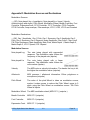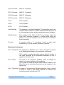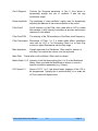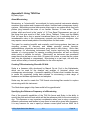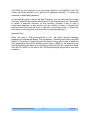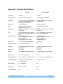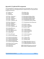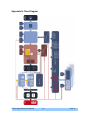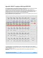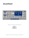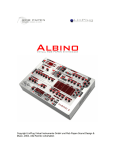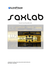
1
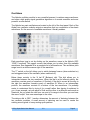
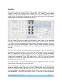
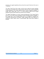
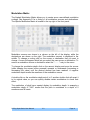
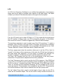
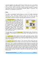
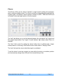
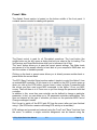
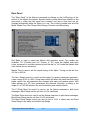
Alpha Series User Manual
Alpha 3
CM Alpha
FREE Alpha
KEYS Alpha
Copyright LinPlug Virtual Instruments GmbH, 2002-2006
All rights reserved
LinPlug Alpha Series User Manual
3.0
Page 1
Welcome
The Alpha Series are software synthesizers designed for creating music on your
personal computer. The Alpha features a subtractive design with special attention
being paid to recreating the warmth and feel typically found in early-1980s analog
synthesizers. Its key features include an easy-to-use interface, a wide range of
oscillator waveforms, fat, rich-sounding filters, as well as numerous processing and
modulation options.
This manual describes all aspects of the Alpha Synthesizer and is designed so that
your use of this software is as efficient and enjoyable as possible. At LinPlug we're
very proud of the Alpha Synthesizer; it's the result of many years of research and
synthesizer programming experience. We hope you get a lot of pleasure using the
Alpha Synthesizer and that it becomes an integral part of your music-making.
Your LinPlug Team,
Berlin, Germany, January 2007
LinPlug Alpha Series User Manual
3.0
Page 2
Credits
Instrument by
Peter Linsener and Pavol Markovič
Manual by
Chris Share and Peter Linsener
Alpha Presets by (alphabetic order)
Dubhad – dh presets
Frank Von Haeven - fvh presets
Frank Neumann – Xnx presets
Guilherme Kalfelz aka WilliamK
Ken Fennell
Klaus-Dieter Pollak aka Summa – sum presets
Laurent Gaudin - ksn-presets
Nico Herz - BT presets
Peter Schelfhout - PS-presets
Sean Steele - LS-presets
Stephan Müsch - SM-presets
T.O.T.C – (T)-presets
Alpha GUI by
Branislav Pakić [email protected]
All technical specifications of the products specified in this manual may be subject to change without notice. The documents
may not be changed, especially copyright notices may not be removed or changed. LinPlug and all LinPlug product names are
LinPlug Alpha Series User Manual
3.0
Page 3
trademarks of LinPlug Virtual Instruments GmbH. Cubase and VST are registered trademarks of Steinberg Media Technologies
GmbH. All other trademarks are the property of their respective owners.
LinPlug Alpha Series User Manual
3.0
Page 4
Table of Contents
Welcome...................................................................................................................................................2
Credits.......................................................................................................................................................3
Overview...................................................................................................................................................5
Controls.....................................................................................................................................................6
Oscillators.................................................................................................................................................7
Mixer.........................................................................................................................................................8
Filter..........................................................................................................................................................9
Amplifier..................................................................................................................................................11
Modulation Matrix....................................................................................................................................13
LFO.........................................................................................................................................................14
Glide........................................................................................................................................................15
Chorus.....................................................................................................................................................16
Preset / Main...........................................................................................................................................17
Rear Panel..............................................................................................................................................19
Get The Full Version...............................................................................................................................20
Glossary..................................................................................................................................................21
Appendix A: MIDI Implementation Chart.................................................................................................22
Appendix B: Oscillator Waveform Types and Ranges............................................................................23
Appendix C: LFO Sync Settings..............................................................................................................23
Appendix D: Modulation Sources and Destinations................................................................................24
Appendix E: Using TUN Files.................................................................................................................27
Appendix F: Technical Specifications.....................................................................................................29
Appendix G: Predefined ECS assignments............................................................................................30
Appendix H: Flow Diagram.....................................................................................................................31
Appendix I: Midi CC mapping on Behringer BCR 2000..........................................................................32
LinPlug Alpha Series User Manual
3.0
Page 5
Overview
There are multiple versions of the Alpha synthesizer available: the full Alpha 3, a
couple of custom Alpha synthesizers with a somewhat reduced featureset and the
AlphaFREE which is publicly available but has the fewest features. See Appendix E
for the differences between the Alpha and the AlphaFREE. This manual describes
the Alpha so some parts may not be applicable to the custom versions of Alpha and
the AlphaFREE.
The Alpha synthesizer is a monotimbral, 32 note-polyphonic AU and VST analoguestyle synthesizer with some extraordinary features. The synthesizer is based upon a
classic subtractive design and includes three oscillator modules, a filter module,
envelope and LFO modules, a chorus effect module and an easy-to-use and
powerful Modulation Matrix.
The structure of the Alpha synthesizer can be divided into 6 sections: Oscillator,
Filter, Amplifier, Modulation (Matrix, LFOs and Glide), Chorus and Master.
Audio signals are generated by an oscillator that gets pitch information from the
synthesizer's MIDI input. The MIDI input is automatically connected to MIDI output of
the host software. The Alpha receives MIDI on all channels simultaneously.
The Alpha contains three oscillators. Each oscillator's pitch, amplitude and symmetry
can be modulated using the Modulation Matrix (Noise can be only modulated in
amplitude).
The output of all oscillators is mixed and routed to the Filter section. The filter
modifies the harmonic spectrum of the oscillator's output mix and has its own
dedicated envelope for controlling the filter cutoff parameter.
The output of the Filter section is then sent to the Chorus section.
The audio outputs of the Alpha are automatically connected to the input of your host
software's mixer. Here you can set the pan position of the Alpha's output.
At various points throughout the signal path you can modulate the signal using either
envelopes, LFOs or MIDI controllers. The Alpha contains 2 independent envelopes
and three LFOs that can be routed to any available modulation destination.
LinPlug Alpha Series User Manual
3.0
Page 6
Controls
Users have the option of controlling all Alpha synthesizer dials in either a circular or a
linear manner depending on the Dial Mode setting on the Alpha's rear panel (see the
"Main" section of this manual for more information about the Alpha's rear panel).
Holding down the ALT key while clicking on a control changes the selected control's
value a minimum step upwards (when clicking in the upper half of the control) or a
minimum step downwards (when clicking in the lower half of the control).
Holding down the CTRL key on PC and Command (Apple) key on Mac while clicking
on a control sets the control to its default value.
.
Holding down the SHIFT key while changing a control's value enables finer control
values to be set.
Double clicking once in a Modulation Matrix slot sets the value of the slot to 0.00.
Double clicking in the same slot a second time resets the slot to its previous value.
All Controls can be automated using external MIDI messages. To do this you need to
use the Alpha's ECS (Easy Controller Setup) which is described in the "Main" section
of this manual.
LinPlug Alpha Series User Manual
3.0
Page 7
Oscillators
The Alpha's oscillator module is very versatile because it contains many waveforms,
and uses a high quality signal generation algorithm so it sounds smoother and more
powerful as ever before.
The Alpha's two main oscillators are located on the left of the front panel. Each of the
Alpha's two oscillator modules outputs a waveform that is a combination of two basic
waveforms. So the amount of available waveforms it literally endless.
Each waveform type is set by clicking on the waveform name in the Alpha's OSC
1/OSC 2 sections. This opens a menu that allows you to select from the available
waveforms. See Appendix B for a complete list of all waveforms. The oscillators pitch
range is set in a similar manner right of the waveform.
The “F” switch on the left allows you to switch between freerun (when switched on)
and retriggered start of the oscillator (when switched off).
Below these controls is the “A bal B” (Balance) dial. This dial allows you to
interpolate between the two waveforms. When the dial is at its leftmost setting, the
waveform consists purely of waveform A. Similarly, if the dial is moved all the way to
the right the waveform consists purely of waveform B. When in an intermediate
position, the waveform consists of a mixture of the two waveforms. It's probably
easier to understand this by trying it for yourself rather than having it explained to
you. As an example, set one wave to Sine and the other to a different wave such as
Sawtooth. As you rotate the dial from one end of its range to the other you can hear
the wave "morph" from one waveshape to the other.
The detune dial in OSC 1 section determines the amount of detuning between the
two oscillator modules. A small amount of detuning can be used to create the
swirling sound typical of many analog synth patches.
LinPlug Alpha Series User Manual
3.0
Page 8
The “ringmod” parameter in Osc 2 section allows a gradually adjustment of how the
output of oscillator 2 is made from oscillator 2 and the integrated Ring Modulator
(see glossary for explanation of AM and ring modulation).
Turned fully left the output of oscillator 2 is purely oscillator 2. Turned fully right the
output of oscillator 2 is fully the ring modulation result of oscillator 1 and oscillator 2.
In middle position the output is mix of oscillator 2 and the ring modulation result of
oscillator 1 and oscillator 2 (in synthesizers often called AM).
The “voices” control below the oscillator controls is used to set the number of
available voices ("polyphony"). The maximum polyphony is 32 voices, but sometimes
it might be useful to restrict the polyphony to save CPU.
Mixer
The upper dial in the Mix section is used to set the relative output volume of each
oscillator module. When the dial is set to 1 (i.e. it is turned all the way counterclockwise) the output signal consists entirely of oscillator 1. When the dial is set to 2
(i.e. it is turned all the way clockwise) the output signal consists entirely of oscillator
2. The mid position provides an equal mixture of oscillator 1 and oscillator 2.
The lower dial is the “noise” parameter that allows to mix gradually some white noise
to the two oscillators mix. Turned fully left no noise is added, turned fully right the
oscillators are suppressed and only noise is audible. The generated noise is white
noise.
LinPlug Alpha Series User Manual
3.0
Page 9
Filter
The Alpha's filter module is located right of the oscillators.
The “drive” (or saturation) dial on the left can be used to overdrive the Alpha's filter.
This can be used to produce warmer, fatter sounds or a thinner sound depending on
the amount of drive applied and depending on the basic waveform.
Below the drive there is the filter “fm” dial and filter fm source selector. With the “fm”
dial the amount of filter cutoff modulation is adjusted from no modulation when
turned fully left to maximum modulation. As the modulation source is in audible
range we have a true “FM” or cutoff Frequency Modulation.
With the fm source selector the source of the modulation is selected, either oscillator
1 , oscillator 2 or noise. Note that the filter cutoff FM does not depend on the setting
in the Mix section of the oscillators. If oscillator 2 is selected then its purely oscillator
2 and does not depend on the ring modulation setting in oscillator 2 section (the Ring
Modulator is not available as source for filter FM).
The “cutoff” dial is used to set the frequency (in Hz) at which the filter begins to take
effect. In the case of the Low Pass Filter, higher settings produce brighter sounds
while lower settings result in darker sounds. In the case of the High Pass filter, higher
settings produce thinner sounds while lower settings result in fuller sounds. The
Band Pass filter combines a Low Pass and a High Pass filter. In this case, the Cutoff
dial sets the midpoint of the filter's pass band.
The “reso” (Resonance) dial is used to set the amount of emphasis around the cutoff
frequency. Higher settings create a more pronounced peak in the signal while lower
settings produce a flatter response.
Below cutoff and resonance is the filter type selector. It allows selection of 4 types of
filter. These are: 12 ("Low Pass 12 dB/Oct."), 24 ("Low Pass 24 dB/Oct."), HP ("High
LinPlug Alpha Series User Manual
3.0
Page 10
Pass 12 dB/Oct.") and BP ("Band Pass 12 dB/Oct.").
The envelope parameters follow below the type selector, these are the classic attack,
decay, sustain and release as well as an additional “fade” parameter. Note that the
envelope has only an effect if the filter envelope depth (described below) is not 0.
The following description of the envelope parameter assumes that the depth is
positive.
The “att” (Attack Time) dial is used to set the length of time it takes for the cutoff
envelope to reach the full envelope depth. For example, if the att dial is set to 0%
(i.e. the dial is turned completely counter-clockwise), the filters cutoff will move from
cutoff parameters value to maximum envelope depth immediately. If the ATT dial is
turned completely clockwise the filters cutoff will move from cutoff parameters value
to maximum envelope depth in 10 seconds.
The “dec” (Decay Time) dial setting determines the length of time (in seconds) that
the filter cutoff envelope takes to move from the maximum envelope depth to the
Sustain value. For example, if the dec dial is set to 0% (i.e. the dial is turned
completely counter-clockwise), the filters cutoff will move from the Attack peak value
to the Sustain value immediately. If the DEC dial is set to 100% (i.e. the dial is turned
completely clockwise) the same change in cutoff frequency will take 10 seconds.
The “sust” (Sustain) dial setting determines the cutoff frequency after the initial
Attack/Decay phase while a note is being held.
The “rel” (Release Time) dial is used to set the length of time (in seconds) that the
cutoff frequency takes to move from current Sustain/Fade value to silence after the
note is released. If the REL dial is set to 0% (i.e. the dial is turned completely
counter-clockwise), the filters cutoff will move from the current level to the cutoff
parameters value immediately. If the REL dial is set to 100% (i.e. the dial is turned
completely clockwise) it takes full 10 seconds.
The “fade” (Fade Time) dial is used to set the rate at which the filters cutoff
frequency moves from the Sustain value to either the cutoff parameters value (when
the dial is turned completely counter-clockwise) or maximum envelope depth (when
the dial is turned completely clockwise). A middle “fade” setting (dial is set to 12
o'clock position) means that the filters cutoff frequency remains at the Sustain level
until the note is released.
The “depth” dial is used to set the degree to which the filter's envelope effects the
signal. Setting “depth” to -100% (i.e. turning the dial completely counter-clockwise)
means that the envelope has full negative effect on the filter. Adjusting the dial to the
middle position means that it has no effect on the filter. Setting “depth” to 100% (i.e.
turning the dial completely clockwise) means that the filter is modulated by the
envelope's full range.
The negative envelope depth can be used in example for opening the Filter when a
note is released (this is impossible with a non-inverted ADSR envelope).
LinPlug Alpha Series User Manual
3.0
Page 11
Amplifier
The amplifier sections follows right of the filter section. It features both a “vol” volume
control to adjust the overall output volume. The “vel” velocity control allows
adjustment of the influence that the notes velocity has on volume. When turned fully
to the left the Velocity has no influence on the volume while turned fully right meants
that the volume is completely controlled by velocity.
The “att” (Attack Time) dial is used to set the length of time it takes for the amplitude
envelope to reach the full envelope depth. For example, if the att dial is set to 0%
(i.e. the dial is turned completely counter-clockwise), the signal's amplitude will move
from zero to full volume immediately. If the ATT dial is turned completely clockwise
the signal's amplitude will move from zero to full volume in the maximum time of 10
seconds.
The “dec” (Decay Time) dial setting determines the length of time (in seconds) that
the amplitude envelope takes to move from the Attack peak level to the Sustain
level. For example, if the dec dial is set to 0% (i.e. the dial is turned completely
counter-clockwise), the signal's amplitude will move from the Attack peak level to the
Sustain level immediately. If the DEC dial is set to 100% (i.e. the dial is turned
completely clockwise), the signal's amplitude will move from the Attack peak level to
the Sustain level in 10 seconds.
The “sust” (Sustain Level) dial setting determines the amplitude level after the initial
Attack/Decay phase while a note is being held.
The “rel” (Release Time) dial is used to set the length of time (in seconds) that the
amplitude envelope takes to move from current Sustain/Fade level to silence after
the note is released. If the REL dial is set to 0% (i.e. the dial is turned completely
counter-clockwise), the signal's amplitude will move from the current Fade level to
zero immediately. If the REL dial is set to 100% (i.e. the dial is turned completely
LinPlug Alpha Series User Manual
3.0
Page 12
clockwise), the signal's amplitude will move from the current Fade level to the zero in
10 seconds.
The “fade” (Fade Time) dial is used to set the rate at which the signal amplitude
moves from the Sustain level to either silence (when the dial is turned completely
counter-clockwise) or full output (when the dial is turned completely clockwise). A
middle “fade” setting (dial is set to 12 o'clock position) means that the signal
amplitude remains at the Sustain level until the note is released.
The “spread” dial allows you to play 3 voices simultaneously. If the “spread” dial is
set to 0% (i.e. the dial is turned completely counter-clockwise), Spread is disabled. If
the “spread” dial is set to anything other than 0%, the Alpha's six oscillators are
continuously detuned with one another. Higher settings create more detuning, so
producing a fatter, thicker sound. A small indicator light shows when Spread is
enabled.
LinPlug Alpha Series User Manual
3.0
Page 13
Modulation Matrix
The Alpha's Modulation Matrix allows you to create seven user-defined modulation
routings. See Appendix D for a listing of all modulation sources and destinations.
The Alpha's Modulation Matrix is located in the top right of the front panel.
Modulation sources are shown in a column on the left of the display, while the
destinations are shown on the right. The modulation amount is displayed in the
middle. To change a routing click on the source or destination that you want to
change. A menu will appear which lets you select the new source or destination. To
remove a modulation source or destination select the "- - - - -" entry in the menu.
To change the modulation depth click on the amount display and move the mouse
(while keeping the mouse button pressed) upwards or downwards (increasing or
decreasing the value) until the desired amount has been reached. A negative
modulation depth inverts the waveform of the modulation source.
A double click on the modulation depth sets it to 0, another double click will revert it
to its original value, so you can quickly disable certain modulations to check their
effect.
The modulation of pitch has a special display for modulation depth. In example a
modulation depth of "2:40" means that the pitch is modulated to a depth of 2
semitones and 40 cents.
LinPlug Alpha Series User Manual
3.0
Page 14
LFO
An LFO (Low Frequency Oscillator) is an oscillator that generates a low frequency
signal that can be used to modulate other aspects of the audio signal. The Alpha
contains up to three LFOs below the matrix on the right of the front panel.
First, the LFO can be set to either “M” Mono or “P” Poly mode with the switch below
the LFO number. In Mono mode, one LFO is shared by all voices. In Poly Mode,
each voice has its own LFO which is triggered by a Note-On MIDI message.
The waveform parameter is used to select one of the LFO waveforms. To select a
waveform, click in the box to the right of the LFO number. A popup menu containing
six LFO waveforms will be displayed. The six available LFO waveforms are: Sine,
Triangle, Sawtooth, Square, Noise and SamHo (Sample and Hold).
The Sync popup menu below the waveform allows you to set the LFO so that it is
"synced" to the tempo of the current song. In this case, the LFO will sync its tempo to
the song tempo (see Appendix C for the range of possible sync settings) For
example, a setting of 1/4 will make the LFO cycle last exactly one quarter note.
The value “Off” indicates that the LFO is not synchronized to the song tempo.
Instead the LFO speed can be adjusted with the “freq” parameter.
The “freq” (Frequency) dial is used to set the the LFO's frequency. If the FREQ dial
is set to 0% (i.e. the dial is turned completely counter-clockwise), the LFO oscillates
at 0.01 Hz (that is 1 complete cycle every 100 seconds). If the FREQ dial is set to
100% (i.e. the dial is turned completely clockwise), the LFO oscillates at 32.0 Hz (32
cycles per second). This parameter is not available for the third LFO. This parameter
is not active whenever a sync value is selected from the Sync popup menu.
The “att” (Attack Time) dial is used to set the length of time it takes for the LFO to
reach the full modulation depth. This can be used to slowly increase the amount of
LinPlug Alpha Series User Manual
3.0
Page 15
modulation applied to the audio signal. If the “att” dial is set to 0% (i.e. the dial is
turned completely counter-clockwise), modulation commences immediately. If the
ATT dial is set to 100% (i.e. the dial is turned completely clockwise), modulation
depth moves from zero to the maximum modulation depth in 10 seconds. This
parameter is not available for the third LFO.
Glide
The Glide or "portamento" section allows you to set the Alpha's portamento
parameters. "Glide" continuously changes the pitch from one note to the next,
connecting the notes and letting you smoothly "glide" from one to the other. The
Glide section is located on the right of the front panel beneath the LFO section.
The Glide Mode button has 4 values: Off, On,
Held and Bend. The On and Off functions turn
"Glide" on and off. When "Glide" is on, the
Time/Rate dial is used to set the length of time
it takes for the pitch of one note to reach that
of a following note. The "Held" setting works
as follows. If notes overlap then Glide is
applied, however if they don't then the notes
are played without Glide. This makes it
possible to apply Glide only to selected notes.
"Bend" allows you to apply a predetermined
pitch bend to each note.
The bend range is set using the Bend control. A bend range of -48 to +48 semitones
is available. This parameter only has a meaning when the Glide Mode button is set
to “Bend”.
The Time/Rate dial is used to adjust the time it takes for the glide to happen. Turned
fully counter clockwise the glide is so fast that its hardly noticeable. If the dial is
turned fully clockwise it takes very long for the notes to glide from the previous notes
pitch to their own pitch.
The Time/Rate button has two settings: Time and Rate. These settings determine
the manner in which the pitch of one note moves to that of the a following note.
When set to "Time", it takes a constant amount of time to move from one note to the
next. In this case it will take the same amount of time to reach the destination pitch
regardless of whether the preceding note was a semitone away or an octave away.
When set to "Rate", the pitch of one note moves to that of a following note at a
constant rate. This means that the amount of time it takes to move from one note to
the next depends upon how far apart the pitches of the two notes are. The further
apart the notes, the longer it will take for the pitch of the first note to reach that of the
following note.
LinPlug Alpha Series User Manual
3.0
Page 16
Chorus
The Chorus effect can be used to "thicken" a single sound creating the impression
that it contains multiple voices. The Chorus works by mixing delayed signals with the
original signal. The Alpha's Chorus features controls for WET, TIME and RATE and
is located in the lower right section of the front panel.
The “wet” dial allows you to set the balance between the processed "wet" signal and
the original unprocessed "dry" signal. A small indicator light shows when Chorus is
enabled.
The “time” dial is used for setting the chorus' delay time (in milliseconds). Longer
times produce a "chorusing" effect while shorter times create a "flanging" effect.
The “rate” dial sets the rate at which the signal is modulated.
To set the chorus' sound we suggest you start with all controls at a medium position
and successively change them until you find a sound that you like.
LinPlug Alpha Series User Manual
3.0
Page 17
Preset / Main
The Alpha's Preset section is located on the bottom middle of the front panel. It
contains various controls for dealing with presets.
The Preset control is used for all File-related operations. The Load button (the
middle button on the left) opens a dialog that lets you select a file for loading. The
Up/Previous and Down/Next buttons allow you to traverse a list of files.
The “save” button allows you to save the current preset settings. The Alpha loads
and saves all of its presets directly to hard disk so your computer's RAM does not
limit the number of available presets.
Clicking on the bank or preset name allows you to directly access another bank or
preset within the current bank.
The ECS (Easy Controller Setup) section makes it simple to control the Alpha 3 from
an external MIDI controller. All you have to do is switch on the ECS (a menu pops up
when you click at the ECS letters, choose Learn), select a Alpha 3 parameter with
the mouse and then send some MIDI messages to the Alpha 3 from you MIDI
source. That's all there is to it! From now on you can change the parameter with that
controller.
In addition to this, more than one controller can be defined to change a particular
parameter. In fact, you can define up to 128 parameter-controller-combinations. This
does not depend on the type of controller you have nor the particular MIDI Control
Change messages it sends.
Don't forget to switch off the ECS (pick Off from the menu) after you have finished
using it (the ECS button remains red during ECS activity as a reminder)!
ECS settings can be saved and restored using the "Load" and "Save" functions from
the menu. In addition, a single controller assignment can be cleared using the
LinPlug Alpha Series User Manual
3.0
Page 18
"Clear" menu entry. All you have to do is select Clear and select a controls that you
wish to be cleared (deassigned from MIDI CC's). Don't forget to switch off the ECS
control after you have finished clearing assignments!
The “Clear All” function clears all controller assignments at once and the Rest.Fact.
Function means Restore Factory, thus restoring the factory settings as described in
Appendix G.
The GEN button is used to generate random patch settings. To generate a new
patch click on the button and some or all of the current parameter settings will be
changed to new settings. The Gen range is set on the Alpha's rear panel (see
below).
LinPlug Alpha Series User Manual
3.0
Page 19
Rear Panel
The "Rear Panel" of the Alpha is accessed by clicking on the LinPlug logo at the
bottom of the Alpha's front panel. Several master controls have been located on the
rear panel to make the front panel less crowded, and also so that they are not
changed accidentally while the Alpha is in use. The controls located here are Dial
Mode, MasterTune, Gen Range, Bend Range, Precision and Microtuning.
Dial Mode is used to select the Alpha's dial operation mode. Two modes are
available: "Cir" (Circular) and "Lin" (Linear). In "Cir" mode the Alpha's dials track
cursor movement in a circular fashion around the dial. In "Lin" mode the Alpha's dials
track vertical cursor movement.
Master Tune is used to set the overall tuning of the Alpha. Tuning can be set from
415 Hz to 466 Hz.
The Gen. Range control is used to set the range for random parameter generation.
It has a range of 0% to 100%. Using lower values will effect the patch less than using
higher values. Not all parameters are changed with each new random patch. With
lower settings (e.g. 5%) less parameters are affected. Normally, a setting in the
range of 2 to 10% will produce the most interesting and useable results.
The P (Pitch) Bend Up control is used to set the Alphas response to pitch bend
messages. Bend Range can be set from 0 to 24 semitones.
The Bend Down control is used to set the Alphas response to pitch bend messages.
Bend Down Range can be set from 0 to 24 semitones.
The Bend Down Range control can also be set to “Link” in which case the Bend
Down Range is the same as the Bend Up Range.
LinPlug Alpha Series User Manual
3.0
Page 20
The PRECISION control is used to set the accuracy of the Alpha's signal generation.
When the "Precision" control is set to less than 100% small inaccuracies are
introduced into the waveform at various point in the Alpha's signal chain. This is
useful if you're trying to replicate the warmth of an old analog synthesizer. Precision
can be set in a range from 90% to 100%.
With the Scale control you can load TUN-scaling files. See appendix E for more
details.
Finally, the rear panel also contains your Alpha Synthesizer's truncated serial
number and the version number.
To switch back to the front panel click the LinPlug logo on the rear panel.
Get The Full Version
Obtaining the Full Version of the Alpha is very easy. All you have to do is visit our
online shop at www.linplug.com and purchase a license. As soon as your transaction
has been authorized you will be sent a personal serial number. In most cases this
will only take a few minutes.
After you've installed and opened the full version of the Alpha, go to the instrument's
rear panel. The S/N edit box should read "Enter here". Enter the serial number you
have received into the S/N edit box. If the serial number has not been entered or it
has been entered incorrectly, the full version of the Alpha will not play any notes.
After entering the serial number return to the Alpha's front panel. Now send the
Alpha a few note-on messages. After the Alpha receives the first few note-on
messages it automatically becomes registered.
If you have any questions regarding the Alpha's registration process, please visit our
support-area at www.linplug.com.
LinPlug Alpha Series User Manual
3.0
Page 21
Glossary
AM: AM or "Amplitude Modulation" is a process where the amplitude of one
generator (the carrier) is controlled by another (the modulator). When the frequency
of the modulator is periodic and below the audio range (less than 20 Hz) tremolo is
produced. When the modulation frequency is within the audio range, Ring
Modulation is produced. See also Ring Modulation below.
Amplifier: A signal processing device that changes the amplitude, and hence the
volume, of a signal.
Envelope: A time-varying signal used to control the development of another signal
after it has been triggered. Envelopes are most often used for controlling a signal's
amplitude. The shape of the envelope is determined by the number of control
parameters. Usually four parameters are available: Attack Time, Decay Time,
Sustain Level and Release Time.
Filter: A signal processing device that suppresses or "filters" out specific parts of a
signal's frequency spectrum. Numerous types of filter are used in audio synthesis.
These include Low Pass, High Pass, Band Pass and Notch. The tone controls on a
stereo amplifier are one example of an audio filter.
LFO: An LFO or "Low Frequency Oscillator" is a periodic signal source (usually
below audio frequency range) used to modulate another signal parameter. An LFO
can be used for a variety of effects including vibrato (by modulating the pitch) and
tremolo (by modulating the volume).
Modulation Matrix: A signal "junction" where a source signal can be patched so that
it controls a destination signal. The Alpha's Modulation Matrix is used for tasks such
as modulating an oscillator's amplitude by an LFO.
Oscillator: A signal source that generates a periodic waveform at a given frequency.
Ring Modulation: The process of combining two audio signals by multiplication.
Ring Modulation produces sidebands but suppresses both the carrier and
modulating frequencies. Though Ring Modulation is only a special form of AM, in
practice “AM” is considered Ring Modulation plus the carrier (one of the oscillators, in
Alpha its the oscillator 2) and “Ring Modulation” is considered pure Ring Modulation
with no carrier.
LinPlug Alpha Series User Manual
3.0
Page 22
Appendix A: MIDI Implementation Chart
Product:
LinPlug Alpha Synthesizer
Version 3.0x
Function
Transmitted
Recognized
Basic Channel
Default
Changed
no
no
no
no
no
no
Omni
no
True Voice
no
no
yes
no
Note On
Note Off
no
no
yes
no
Aftertouch
Poly (Key)
Mono (Channel)
no
no
yes
yes
Pitch Bend
no
yes
Control Change
no
yes
Program Change
no
yes
System Exclusive
no
no
System Common
Song Position
Song Select
Tune Request
no
no
no
no
no
no
System Realtime
Clock
Commands
no
no
no
no
Aux Messages
Local On/Off
All Notes Off
Active Sensing
System Reset
no
no
no
no
no
yes
no
yes
Date: 15.September 2006
Remarks
Mode
Default
Changed
Note Number
Velocity
LinPlug Alpha Series User Manual
3.0
Page 23
Appendix B: Oscillator Waveform Types and Ranges
Types:
Sine, Triangle, Sawtooth, Square1, Square2, Square3, Organ1, Organ2, Organ3,
Spectra1, Spectra2, Spectra3, Spectra4, RichSaw1, RichSaw2, RichSaw3,
RichSaw4, SawSpec1, SawSpec2, VintSaw1, VintSaw2, VintSaw3, SawBass1,
SawBass2, SawBass3, SawBass4, SawBass5, SawBass6, SawBass7, SawBass8
Waveform Ranges:
32", 16", 8", 4", 2"
Appendix C: LFO Sync Settings
Off, 16/1*, 16/1, 16/1T, 8/1*, 8/1, 8/1T, 4/1*, 4/1, 4/1T, 2/1*, 2/1, 2/1T, 1/1*, 1/1, 1/1T,
1/2*, 1/2, 1/2T, 1/4*, 1/4, 1/4T, 1/8*, 1/8, 1/8T, 1/16*, 1/16, 1/16T, 1/32*, 1/32, 1/32T,
1/64, 5/16, 7/16, 9/16, 5/8, 11/16, 13/16, 7/8, 15/16.
Note: "T" stands for Triplet and "*" stands for a dotted note. In the case of a dotted
note, the note duration is equal to 1.5 times its original undotted value.
LinPlug Alpha Series User Manual
3.0
Page 24
Appendix D: Modulation Sources and Destinations
Modulation Sources:
--- (Off), Note played (log = logarithmic), Note played (lin = linear), Velocity,
Aftertouch(poly and mono), Pitch Wheel, Modulation Wheel, Breath Controller, Foot
Controller, ExpressionContr, CC16 Controller, CC17 Controller, CC18 Controller,
CC19 Controller, Amp envelope, Filter envelope, LFO1, LFO2, LFO 3 and Constant
Modulation Destinations:
---(Off), Osc 1 Amplitude, Osc 1 Pitch, Osc 1 Symmetry, Osc 2 Amplitude, Osc 2
Pitch, Osc 2 Symmetry, Osc 2 Ringmod, Noise Amplitude, Filter Cutoff, Filter Cutoff
FM, Filter Resonance, Main Amplitude, Main Pitch, Matrix Depth 1, Matrix Depth 2,
Matrix Depth 3, LFO 1 Speed, LFO 2 Speed
Modulation Sources
Note played Log
The note being played with exponential
response. The modulation value follows the
frequency of the played note (bipolar).
Note played Lin
The note being played with a linear
response. The modulation value follows the
note number (bipolar).
Velocity
The MIDI note-on velocity information. The harder the key is hit,
the higher the modulation value (unipolar).
Aftertouch
MIDI pressure / aftertouch information. Either polyphone or
monophone (unipolar)
Pitch Wheel
The value of the pitch-Wheel is takes as modulation source,
maybe it makes sense to reduce the Pitch Wheel range to 0
when using the Pitch Wheel as modulation source. The Pitch
Wheel is bipolar
Modulation Wheel The MIDI modulation wheel (MIDI CC 1) (unipolar )
Breath Controller
MIDI CC 2 (unipolar).
Foot Controller
MIDI CC 4 (unipolar).
Expression Contr. MIDI CC 11 (unipolar).
LinPlug Alpha Series User Manual
3.0
Page 25
CC16 Controller
MIDI CC 16 (bipolar).
CC17 Controller
MIDI CC 17 (bipolar).
CC18 Controller
MIDI CC 18 (bipolar).
CC19 Controller
MIDI CC 19 (bipolar).
LFO 1
LFO 1 (bipolar).
LFO 2
LFO 2 (bipolar).
LFO 3
LFO 3 (bipolar).
Amp Envelope
The envelope of the Main Amplitude. This envelopes control the
overall Volume, however if it makes sense within the preset to do
so, the envelope can be used as a modulation source (unipolar).
Filter Envelope
The envelope of the Filters Cutoff. This envelopes control the
Filter cutoff frequency, however if it makes sense within the
preset to do so, the envelope can be used as a modulation
source (unipolar).
Constant
A constant value of 1, sometimes useful to apply static
modulation, e.g. of the oscillator symmetry. (unipolar)
Modulation Destinations
Osc 1,2 Amplitude The amplitude of Oscillator 1 to 2, used in example for tremolo
or for adjusting the balance of the oscillators in the sound.
N.B. In order to create the classic tremolo effect it is better to
use Main Amplitude as the modulation destination as this is
applied to the whole voice.
Osc 1,2 Pitch
The pitch of the respective Oscillator, used in example for
vibrato or to control detuning of the oscillators.
N.B. In order to create the classic vibrato effect it is better to use
Main Pitch as the modulation destination as this is applied to the
whole voice.
Osc 1,2 Symmetry Symmetry of the respective Oscillator waveform, used to thicken
a sound or make it swirl, effect depends on intensity and
modulation speed, typically with LFO.
LinPlug Alpha Series User Manual
3.0
Page 26
Osc 2 Ringmod
Controls the Ringmod parameter of Osc 2, thus allows to
dynamically change the mix of oscillator 2 and the ring
modulators output.
Noise Amplitude
The amplitude of noise oscillator, mainly used for dynamically
adjusting the balance of the noise oscillators in the sound.
Filter Cutoff
Cutoff frequency of the Filter, often used with an LFO to create
filter sweeps or with Velocity to simulate an acoustic instrument's
response to note attack.
Filter Cutoff FM
The intensity of the FM modulation of the filters cutoff frequency.
Filter Resonance
Resonance of Filter 1 or 2, a rather subtle effect, sometimes
used with an LFO or for Keyscaling (Note Lin or Note Exp
source) to adjust Resonance over the key range.
Main Amplitude
Overall amplitude of all Oscillators. Often used for tremolo or
with Key Lin to adjust the volume over the keyboard.
Main Pitch
Overall pitch of all oscillators. Often used for vibrato.
Matrix Depth 1,2,3 Intensity of the first three entries (line 1 to 3) in the Modulation
Matrix, often used with the ModWheel as source to control a
specific modulation parameter (e.g. Vibrato).
LFO Speed 1,2
Speed of LFO 1 or 2, this allows tempo changes of the LFO to
be programmed. Typically this is used with Key Lin to make the
LFO run faster with higher notes.
LinPlug Alpha Series User Manual
3.0
Page 27
Appendix E: Using TUN Files
By Jacky Ligon
About Microtuning
Microtuning, or "microtonality" are methods for tuning musical instruments whereby
musicians may explore and compose with ethnic, historical and contemporary tuningsystems. Microtuning musical instruments allows one to use scales which may have
pitches lying between the notes of our familiar Western 12 tone scale. These
pitches which are found in the 'cracks' of 12 Tone Equal Temperament are one of
the things that give music's of Bali, India, Africa, Thailand, Turkey and the Middle
East (to name but a few) a special intonational flavor, but is something that is of
immeasurable value to the contemporary acoustic and electronic composer, who
may require a more broad palette of musical pitches for their music.
The quest for creating beautiful and musically useful tuning-systems has been an
unending process of discovery and debate amongst musical theorists,
mathematicians, physicists and musicians going back to early history. Quite often
the reasons for microtuning instruments may involve improving the consonant
intervals of a tuning-system for sweeter sounding harmonies, as well as offering
wider variety of choices for melody. "Microtuning" an instrument can sometimes
mean there may be less or more than 12 tones in an octave, or even that the octave
itself may be stretched or compressed. Microtuning is a vast topic, rich with lore,
music and an infinity of musical possibilities for the sonic explorer.
Creating TUN microtuning files with SCALA
Scala is a freeware utility developed by Manuel Op de Coul in the Netherlands,
which can be used for the creation and analysis of historical, ethnic and
contemporary microtunings. A powerful capability of Scala is that it enables the user
to create the proprietary tuning data required for microtuning a wide range of
hardware and software synthesizers and samplers.
Scala may be used to create the TUN format microtuning-files needed to explore
microtunings with this instrument.
The Scala home page is http://www.xs4all.nl/~huygensf/scala/
Specifying the Reference Frequency of a Microtuning
One of the powerful capabilities of the TUN file format and Scala, is the ability to
specify the pitch and midi note which will be the reference pitch for the microtuning in
use. This becomes a very important consideration when one is using a number of
different synthesizers and wishes to keep them in tune with a given base frequency.
It is very common for one to specify a chosen concert pitch such as A440 Hz or
LinPlug Alpha Series User Manual
3.0
Page 28
C261.6256 Hz as a reference for a microtuning, however, the flexibility of the TUN
format and Scala enables one to specify this frequency arbitrarily. In Scala this
reference is called Map Frequency.
As well as being able to specify the Map Frequency, one can also specify a central
midi-note, which will become the starting point for the microtuning in use. Being able
to specify a particular midi-note on the controller, provides a way to map a
microtuning beginning on any desired midi key, making it easier to navigate the
keyboard when there may be more or less than 12 tones per octave, or where one
may desire to have the notes of a tuning fall on certain physical keys.
Important Note
When one uses a TUN microtuning-file in the , the above specified mapping
properties will override the Master Tuning reference. Normally when one is using the
default 12 Tone Equal Tempered Scale, the Master Tuning will be used to make fine
pitch adjustments around the standard concert pitch of A440 Hz, but when one has
specified another pitch base for a microtuning when the TUN file is created in Scala,
such as C261.6256 Hz, the data in the TUN microtuning-file will provide a new pitch
reference.
LinPlug Alpha Series User Manual
3.0
Page 29
Appendix F: Technical Specifications
ALPHA 3
ALPHA FREE
Polyphony
32 voices
8 voices
Preset Memory
Unlimited (direct disk based)
Unlimited (direct disk based)
Oscillators
2 + Noise (Osc Pitch, Amplitude and
Symmetry modulateable), freerun
switchable, Ring Modulator
30 x 30 Waveforms
2 (Pitch, Amplitude and Symmetry
modulateable)
Filter
LP12, LP24, BP12, HP12 with
Saturation and Filter FM
LP12, LP24, BP12, HP12
Envelopes
ADSFR for Amplitude and Cutoff (may ADSFR for Amplitude and Cutoff (may
be inverted)
be inverted)
LFO
1 LFO, 6 Waveforms, Syncable to
Tempo, Attack adjustable
Portamento/Glide
3 LFO's 6 Waveforms, Syncable to
Tempo, Attack adjustable, Mono/Poly
Mode
Mono & polyphonic
Normal, Held and Auto-Bend (+- 48
semitones) Mode
with adjustable Time or Rate
Voice Limit
1 to 12 voices or All (32 voices)
1 to 8 voices
Polyphonic Unison
Yes, spread adjustable
No
Precision
Yes, 90 (analog warmth) to 100%
(digital cold)
Yes, 90 (analog warmth) to 100%
(digital cold)
MIDI Learn
Yes (ECS)
Yes (ECS)
Chorus
Yes, adjustable Depth and Speed
Yes, adjustable Depth and Speed
Master Tune
Yes, 430.0 to 450.0 Hz
No
Modulation Matrix
7 slot, 19 sources, 18 destinations
7 slot, 17 sources, 14 destinations
Pitch Bend Range
Separately adjustable up/down
1 to 24 semitones
Fixed 2 semitones
Patch Creator
Yes, adjustable
No
Microtuning
TUN File support
No
True Mono-Mode
Yes
No
Waveforms
LinPlug Alpha Series User Manual
3.0
30 x 30 Waveforms
Mono & polyphonic
Normal, Held and Auto-Bend (+- 48
semitones) Mode
with adjustable Time
Page 30
Appendix G: Predefined ECS assignments
The following MIDI-CC-parameter-assignments are automatically set up on start-up
of Organ 3. Of course, the assignments can be replaced with your own preferences
using the ECS function.
CC 12 Main Level
CC 14 Spread
CC 15 Exactness
CC 84 Glide Time
CC 85 Glide Mode
CC 86 Glide Bend
CC 20 Osc 1 Waveform 1
CC 21 Osc 1 Range 1
CC 22 Osc 1 Waveform 2
CC 23 Osc 1 Range 2
CC 24 Osc 1 Waveform Mix
CC 88 Amplitude Evelope Attack
CC 89 Amplitude Evelope Decay
CC 90 Amplitude Evelope Sustain
CC 102 Amplitude Evelope Fade
CC 103 Amplitude Evelope Release
CC 26 Osc 2 Waveform 1
CC 27 Osc 2 Range 1
CC 28 Osc 2 Waveform 2
CC 29 Osc 2 Range 2
CC 30 Osc 2 Waveform Mix
CC 104 Amplitude Velocity Responce
CC 105 LFO 1 Attack
CC 106 LFO 1 Waveform
CC 107 LFO 1 Frequency
CC 108 LFO 1 Sync
CC 31 Filter FM Source
CC 69 Osc Detune
CC 70 Osc Ringmodulation
CC 71 Osc Balance
CC 72 Noise Level
CC 110 LFO 2 Attack
CC 111 LFO 2 Waveform
CC 112 LFO 2 Frequency
CC 113 LFO 2 Sync
CC 73 Filter FM Depth
CC 74 Filter Envelope Depth
CC 115 LFO 3 Waveform
CC 116 LFO 3 Sync
CC 75 Filter Envelope Attack
CC 76 Filter Envelope Decay
CC 77 Filter Envelope Sustain
CC 78 Filter Envelope Fade
CC 79 Filter Envelope Release
CC 117 Chorus Wet
CC 118 Chorus Time
CC 119 Chorus Rate
CC 80 Filter Cutoff Frequency
CC 81 Filter Resonance
CC 82 Filter Drive
CC 83 Filter Type
LinPlug Alpha Series User Manual
CC 25 Matrix Modulation Amount 1
CC 87 Matrix Modulation Amount 2
CC 109 Matrix Modulation Amount 3
NRPN 1024/1025 Preset previous/next
NRPN 1026/1027 Bank previous/next
3.0
Page 31
Appendix H: Flow Diagram
LinPlug Alpha Series User Manual
3.0
Page 32
Appendix I: Midi CC mapping on Behringer BCR 2000
On the LinPlug website you find a MIDI CC mapping for owners of the Behringer BCR 2000 controller,
so the BCR2000 can be optimally used with the Alpha 3 synthesizer.
Only the first row of switches below the top row of dials is used for this “Alpha3 BCR2000.syx”
template. The Fade F and Fade A switches are a quick option to set the Fade parameter of the Filter
and Amplitude envelope to neutral (no fade, thus a standard ADSR). The MW assignment is the
Modulation Wheel (just in case you not have any on your MIDI keyboard).
All other assignments should be pretty clear from the drawing below. We suggest you print it and put it
aside your BCR 2000 until you got familiar with it.
To load the mapping into your BCR2000 you need to transfer the MIDI system exclusive data file
“Alpha3 BCR2000.syx. This might be able right from your host or with a MIDI tool like “SysEx Librarian”
on Mac or “MIDI-OX” on PC.
Note that the mapping only works as expected with the ECS Factory Settings as described in
Appendix G.
LinPlug Alpha Series User Manual
3.0
Page 33