1
sat-nms LFTX/RX
Optical Links
User Manual
Version 1.3 / 2010-07-09
© Copyright
SatService Gesellschaft für Kommunikatiosnsysteme mbH
Hardstrasse 9
D-78256 Steisslingen
www.satnms.com
www.satservciegmbh.de
Tel +49 7738 97003
Fax +49 7738 97005
SatService
Gesellschaft für Kommunikationssysteme mbH
Table Of Contents
Table Of Contents ................................................................................................................................. 1
1 Introduction ........................................................................................................................................ 3
2 Installation ......................................................................................................................................... 5
2.1 Safety Instructions ........................................................................................................................ 5
2.2 Setting the IP Address .................................................................................................................. 5
2.3 Mechanical installation ................................................................................................................. 6
2.4 Connecting the sat-nms LFTX/RX ................................................................................................ 6
2.4.1 Optical receiver and transmitter cards ..................................................................................... 7
2.4.2 Power connectors and power supplies ..................................................................................... 7
2.4.3 D/C and data connectors ......................................................................................................... 7
2.3.4 RF connectors ........................................................................................................................ 8
2.3.5 Optical connectors ................................................................................................................. 8
2.4 Configuring the Optical Links ....................................................................................................... 8
3 Operation ......................................................................................................................................... 10
3.1 The Web-based User Interface ................................................................................................... 10
3.2 Display Readings ....................................................................................................................... 10
3.2.1 Reading of LFRX receiver card ............................................................................................ 10
3.2.2 Reading of LFTX transmitter card ......................................................................................... 11
3.2.3 Reading of empty slots .......................................................................................................... 11
3.3 Configuration of operational parameters ...................................................................................... 11
3.3.1 Configuration of LFRX receiver card .................................................................................... 11
3.3.2 Configuration of LFTX transmitter card ................................................................................. 12
3.3.3 Empty slots .......................................................................................................................... 12
3.4 General Setup ............................................................................................................................ 12
3.4.1 Master/Slave mode parameters ............................................................................................. 13
3.4.2 Redundancy parameters ........................................................................................................ 13
3.4.3 Configure the master/slave mode ........................................................................................... 14
3.4.4 Real Time Clock battery backup ........................................................................................... 14
3.5 Front panel Operation ................................................................................................................. 14
3.5.1 Display Mode ....................................................................................................................... 15
3.5.2 The Main Menu .................................................................................................................... 15
3.5.3 Editing Numeric Parameters ................................................................................................. 16
3.5.4 Editing Multiple Choice Parameters ...................................................................................... 16
3.5.5 Fault Display ........................................................................................................................ 16
3.5.6 Local operation LFRX Card .................................................................................................. 17
3.5.7 Local operation LFTX Card .................................................................................................. 18
4 Remote Control ................................................................................................................................ 19
4.1 General command syntax ............................................................................................................ 19
4.2 The TCP/IP remote control interface ........................................................................................... 19
4.3 The RS232 remote control interface ............................................................................................ 19
4.4 SNMP Control ............................................................................................................................ 20
4.5 Parameter list ............................................................................................................................. 20
5 Theory of Operation ......................................................................................................................... 23
(C) 2013, SatService GmbH
www.satnms.com
LF-UM-1301 Page 1/28
SatService
Gesellschaft für Kommunikationssysteme mbH
5.1. Frequency bands ........................................................................................................................ 23
5.2 Connectors ................................................................................................................................. 24
5.3 Controller Module ...................................................................................................................... 24
5.4 Redundancy switching ................................................................................................................ 24
5.5 Outline Drawing ......................................................................................................................... 26
6 Specifications ................................................................................................................................... 28
(C) 2013, SatService GmbH
www.satnms.com
LF-UM-1301 Page 2/28
SatService
Gesellschaft für Kommunikationssysteme mbH
(C) 2013, SatService GmbH
www.satnms.com
LF-UM-1301 Page 3/28
SatService
Gesellschaft für Kommunikationssysteme mbH
1 Introduction
This document is the user manual provided with the sat-nms LFTX/RX fiber optical link equipment. It
contains all necessary information how to install, setup, and operate the unit. The user manual is available as
a printed document and for on-line reading on the optical links itself as well.
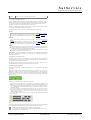
T he sat-nms LFTX/RX fiber optical link is a high performance transmission system which transmits a
complete frequency band, with all its separate carriers, over a single mode fiber with length up to 5km. The
big advantages of fiber optical links are:
Lightning protection
Fully isolated between the two destinations
No ground loops
bug proof
Two types of optical converters are available
sat-nms LFTX optical transmitter which converts from IF input spectrum to optical output at 1310nm
sat-nms LFRX optical receiver which regenerates the optical signal back to an IF spectrum
SatService offer the LFTX/RX modules for different frequency bands.
sat-nms LFRX-L and LFTX-L
950 to 2150MHz
sat-nms LFRX-B and LFTX-B
50 to 2150MHz
sat-nms LFRX-10 and LFTX-10 950 to 2150MHz and 10MHz reference frequency for BUC
The paragraphs below give a short overview to the contents of the documentation. A subset of this
documentation is stored on the device itself, the complete documentation is available on the sat-nms
documentation CD and at www.satnms.com.
Installation: The installation chapter guides through the installation and setup of the sat-nms LFTX/RX
. It describes the mechanical concept of the chassis and the assignment of the connectors. Finally you
learn in this chapter how to set the sat-nms LFTX/RX's IP address, which is a essential precondition
to operate the sat-nms LFTX/RX by means of a web browser. This section is available in the printed
version only.
Operation: The sat-nms LFTX/RX is operated using a standard web browser like the Internet-Explorer
or Mozilla Firefox. The user interface design is straight forward and clearly structured. Operating the
sat-nms LFTX/RX is mostly self-explanatory. Nevertheless, the 'Operation' chapter outlines the map
of web pages which make up the sat-nms LFTX/RX user interface and elaborately describes the
meaning of each alterable parameter.
Remote Control: The sat-nms LFTX/RX provides a versatile remote control interface. A monitoring &
control software may fully operate the sat-nms LFTX/RX either through a TCP/IP network
connection or through the RS232 interface of the sat-nms LFTX/RX. This chapter describes the
communication protocol used for remote control and lists all parameters accessible through the remote
interface.
Theory of Operation : This chapter gives a short overview how the optical links work and which
features are supported.
Specifications: At the end of the document, the specifications applicable to the sat-nms LFTX/RX are
summarized in this chapter.
Support and Assistance
If you need any assistance regarding our sat-nms Optical Links, don't hesitate to contact us. We would be
pleased to help you by answering your questions.
SatService GmbH phone +49 7738 9700-3 or -4
Hardstrasse 9
fax +49 7738 97005
78256 Steisslingen www.satnms.com
- Germany Version 1.3 / 2010-07-09
(C) 2013, SatService GmbH
www.satnms.com
LF-UM-1301 Page 4/28
SatService
Gesellschaft für Kommunikationssysteme mbH
2 Installation
This chapter describes how to install the sat-nms LFTX/RX Fiber Optical Link. You find a guide how to
connect, configure and mechanically mount the equipment below.
Before you start, please first read the Safety Instructions chapter below. It contains some important
recommendations to prevent damage from the equipment.
Then, we strongly recommend to do a first setup of the unit on a lab desk before installing it at it's final
location. This is mainly for the following reason:
1. To setup the IP parameters, the PC used for configuring and the chassis must either be connected to
the same Ethernet hub / switch or must be connected directly with a crossover cable. The initialization
program does not work through routers intelligent network switches.
Hence, the typical sequence of tasks when putting an sat-nms LFTX/RX into operation is as follows:
1.
2.
3.
4.
5.
Read the chapter Safety Instructions
Set the unit's IP address
Mechanically installation of the chassis
Connecting the LFTX/RX
Configuring the LFTX/RX
2.1 Safety Instructions
Failure to observe all Warnings and Cautions may result in personnel injury and/or equipment damage not
covered by the warranty.
ATTENTION Optical Radiation! If connected to a power supply, the unit provides invisible Laserradiation. The source is class 3R Laser diode as defined in DIN EN 60825-1:2001-11. P0=2mW,
Lambda=1310nm. Never look into fiber-optical components like connectors or fibers. Use an infrared
viewer, optical power meter or fluorescent screen for optical output verification.
Do not allow any dirt or foreign material to get into the optical connector bulkheads. This may cause
damage to the polished optical connector end faces
Follow standard Electrostatic Discharge (ESD) procedures when handling a the chassis and the
modules of the LFTX/RX.
Select and apply the appropriate 110…240AC voltage according to the data sheet and documentation
before connecting power.
Depending on configuration, the chassis is equipped with User-changeable power supplies. Always
disconnect the mains of the power supply that has to be changed. Wait at least 10s after disconnecting
the mains (for internal discharge of the power supply) before removing the power supply
ATTENTION: To avoid the possibility of an electrical shock, never handle with a power supply that is
connected to mains.
The power supplies are EMI filtered. The chassis is connected to earth ground in compliance with
safety requirements. Always use the 3-prong AC plug with earth ground to avoid possibility of
electrical shock hazard to personnel.
Before you connect the LFTX/RX to an L-Band distributor or LNC , please make sure that the unit to
which you connect can handle 15V D/C voltage on its RF L-Band input. Some L-Band IF distribution
equipment does not have D/C blocks included and the unit could be damaged. If you are not sure how
the interfacing equipment will behave, switch off the LNC supply voltage in the Setup menu or in case
of local controlling by hardware switch before you connect the cable.
The LFTX/RX can be damaged if the total RF input power is higher than +10dBm specified
maximum value. Do not connect equipment where the total output power is higher than the specified
value of the data sheet or indicated on the LFTX/RX unit.
In case of a failure do not open the sat-nms LFTX/RX, you will loose warranty, call SatService
GmbH for an RMA number.
Observe normal safety precautions when operating, servicing, and troubleshooting this equipment.
Take standard safety precautions with hand and/or power tools.
When connecting the units fault relay circuits, observe the maximum ratings: 110V D/C 300mA, 125V
A/C 500mA.
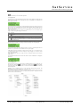
2.2 Setting the IP Address
Before you can operate the sat-nms LFTX/RX Optical Link, you need to set the unit's IP address. There is
a special configuration program on the documentation CD shipping with the unit for this purpose. We
recommend to configure LFTX/RX' TCP/IP settings before you install chassis at it's final place. To
configure LFTX/RX, the following equipment is required:
The sat-nms LFTX/RX L-Band Optical Link itself
110…240V A/C power
A Computer running a Microsoft Windows operating system equipped with CD-ROM drive and
Ethernet network card.
A CAT5 crossover network cable or a Ethernet hub/switch and standard network cables to connect the
LFTX/RX and the computer.
The CD-ROM shipping with the sat-nms LFTX/RX.
Setting the chassis' IP parameters now is easily done within a few minutes.
1. First install a network cable between the LFTX/RX chassis and your computer. If you have a
crossover cable available, this is very easy: simply put the cable into the network connectors of
computer and LFTX/RX chassis. Without a crossover cable, you need to connect both, the computer
and LFTX/RX chassis to the same network hub or switch using two standard network cables. It is
essential, that the computer and the LFTX/RX chassis are connected to the same network segment,
the configuration program is not able to find the LFTX/RX chassis through routers or network
switches.
2. Now power on your computer and connect LFTX/RX chassis to the 110…240V A/C supply.
3. Insert the CD-ROM into the computer's drive and inspect it's contents through the 'My Computer' icon
on your desktop. Double-click to the 'ChipTool.exe' program in the 'ChipTool' directory.
4. When the ChipTool program is running, type CTRL+F to make the program search the LFTX/RX.
The program shows a list containing at least one entry describing the actual network parameters of the
LFTX/RX.
(C) 2013, SatService GmbH
www.satnms.com
LF-UM-1301 Page 5/28
SatService
Gesellschaft für Kommunikationssysteme mbH
5. The serial number shown in the first column of the list, must match the serial number printed on the
processor's enclosure. If the list stays empty, the LFTX/RX chassis is not connected properly. If there
are more entries in the list, the configuration program has found other devices in this network segment
which use the same technology.
6. Now type CTRL+I to open the IP configuration window of the program. In this form enter the
processor's serial number, it's new IP address and network mask. If the LFTX/RX later shall be
operated through a router, enter the address of the router on the gateway field, otherwise leave this
field blanc. Be sure, that the 'DHCP' mark is unchecked. Finally click to the 'Yes' button to set the
new parameters at the LFTX/RX chassis.
Now the IP configuration of the chassis is completed. You may finally want to test if the LFTX/RX chassis
is reachable now. Start your web browser and type the chassis' IP address into the URL field of the browser.
The LFTX/RX should reply with it's main page, provided that the chassis and your computer are configured
for the same subnet.
2.3 Mechanical installation
The sat-nms LFTX/RX enclosure is a standard 2HU 19" rack-mountable enclosure. Use slide bars to install
the chassis, because the mounting angles will not be able to hold the chassis in the horizontal position. Fix
the enclosure with 4 according screws to a 19" Rack. Don´t forget to connect the "GND"-screw to the Rack.
When planning the mechanical installation of the chassis, please consider that the connectors are placed at
the front and the backside of the enclosure. Depending on the flexibility of the cables you are going to use,
you will require about 10 centimeters space for cabling on both sides of the chassis.
2.4 Connecting the sat-nms LFTX/RX
The connectors of the chassis are placed on the front and on the rear side. The Front side contains the fiber
optic connectors and the L-Band test-ports, the rear side contains the corresponding L-Band In/Out
connectors and also the the AC-power and Data-connectors.
When you connect the L-Band Optical Link chassis, please consider the following:
J1.2 LAN is the Ethernet 10Base-T / RJ45 connector. Use a standard network cable to connect the
LFTX/RX to an Ethernet hub or switch. If you want to connect your computer and the unit directly
without using a hub, you need a crossover cable for this with swapped RX/TX lines.
J1.1 serial is a standard 9-pin RS232 (DCE) SUB-D pin-connector. You may use a direct 9-pin cable
to connect a PC to the LFTX/RX. The RTS/CTS and the DTR/DSR lines are bridged in the unit to
simulate hardware handshaking. They need however not to be connected, if you want to use a 3 wire
cable.
J1.3 Alarm is a standard 9-pin SUB-D socket-connector. This connector contains the alarm contacts
of the internal failure relays.
PS1 and PS2 are the power-inputs. Use only IEC plugs to connect the power supplies. Do not forget to
connect the "GND"-labeled screw to the ground potential.
The input, output and Test-port RF-connectors are all SMA/50Ohm female in the standard
configuration.
The fiber optic connectors are E2000 or FC/APC types depending on the configuration.
(C) 2013, SatService GmbH
www.satnms.com
LF-UM-1301 Page 6/28
SatService
Gesellschaft für Kommunikationssysteme mbH
2.4.1 Optical receiver and transmitter cards
Attention: Optical Radiation!
If connected to a power supply, the LFTX/RX provides invisible laser radiation. The source is class 3R
Laser diode as defined in DIN EN 60825-1:2001-11 with P0=2mW, Lambda=1310nm. Never look into
fiber-optical components like connectors or fibers. Use an infrared viewer, optical power meter or
fluorescent screen for optical output verification.
It is possible to realize up to 10 optical links with one sat-nms LFTX/RX chassis.
On the front side of the enclosure, you find 10 slots, where up to 10 cards can be placed in. If the chassis is
equipped with the redundancy enhancement, it is possible, to use slot 3 and/or slot 8 as redundant slots.
Read chapters Config Parameters and Setup Parameters for instructions how to use this configuration and
how to configure the redundancy.
It is possible to place a LFRX or LFTX card in every slot. To install the desired card, put it into the slide rail
until the front plate of the card contacts the mounting rail. The card has to slide in smoothly. If not, pull the
card out and try again. Otherwise the connectors on the card edge or on the backplane might be damaged.
After that fix the card with the provided screws to ensure a proper contacting of the connectors on the
LFRX or LFTX card with the connectors on the backplane.
Now you have to configure the system after placing a LFRX or LFTX card. How to do this, is described in
chapter Config Parameters.
To release a card, open the screws with which the card is fixed at the mounting rail. Now turn in the screw
into the screw thread beside to push the card out of its socket. After that you can pull the card out of the
unit.
2.4.2 Power connectors and power supplies
Power connectors
At first, connect the screw, labeled with "GND" to Ground (e.g. to the 19"-Rack the chassis is mounted in).
After that connect the chassis to 110…240V A/C via IEC connectors. The sat-nms LFTX/RX is running
with only one connected power supply as well, but we strongly recommend to use two different power
supplies to ensure the maximal system stability. In case of one power supply breaking down, the system will
still be running without problems.
Power supplies
Depending on the configuration, the power supplies can be changed during the LFTX/RX chassis is running.
To change a power supply, always disconnect the mains of the power supply that has to be changed and
wait at least 10s (for internal discharge). Open the 2 screws with which the power supply is mounted an pull
the power supply, using the attached handle bar, out of the unit.
To put in a power supply, you have to do the same things in reverse chronology: Put the power supply into
the slide rails, until the front plate contacts the mounting rail. After that fix the power supply with the
provided screws to ensure a proper contacting of the connectors on the power supply with the connectors
on the backplane.
ATTENTION: To avoid the possibility of an electrical shock, never handle with a power supply that is
connected to mains.
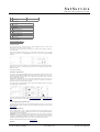
2.4.3 D/C and data connectors
The Alarm and data connectors of the sat-nms LFTX/RX chassis all are located at the rear side of the
enclosure up right. The figure below illustrates the location of the connectors and the pin out.
The LED PS shows the presence of one or two power supply(ies). The LNK LED turns on, when there is
some traffic on the LAN, the chassis is connected to.
To release the MNC board, open the screws with which the card is fixed at the mounting rail. Now turn in
the screw into the screw thread beside to push the card out of its socket. After that you can pull the card out
of the unit.
To install the MNC board again, put it into the slide rail until the front plate of the card contacts the
mounting rail. Please pay attention: The board has to slide in smoothly. If not, pull the card out and try
again. Otherwise the connectors on the MNC board or on the backplane might be damaged. After that fix the
card with the provided screws to ensure a proper contacting of the connectors on the MNC board with the
connectors on the backplane.
J1.1 Alarm connector
Pin Alarm contacts (DSUB-9 male)
1
NC1
closed if ok, open in fault state
2
COM1
common for fault relay 1
3
NO1
open if ok, closed in fault state
4
not connected
5
not connected
6
NC2
closed if ok, open in fault state
7
COM2
common for fault relay 2
(C) 2013, SatService GmbH
www.satnms.com
LF-UM-1301 Page 7/28
SatService
Gesellschaft für Kommunikationssysteme mbH
8
NO2
9
not connected
open if ok, closed in fault state
J1.3 Serial connector
Pin RS232 serial interface (DCE) (DSUB-9 female}
1
not connected
2
TxD (output)
3
RxD (input)
4
internally bridged to pin 6
5
GND
6
internally bridged to pin 4
7
internally bridged to pin 8
8
internally bridged to pin 7
9
not connected
J1.2 Network Connector
Ethernet 10/100Base-T (RJ45
2.3.4 RF connectors
On the rear side the in-/ out RF-connectors are placed. Depending, which card is placed in the
corresponding slot, the connector is an in- or an output.
If e.g. in slot 1 a LFTX card is placed, the connector I/O 1 is a RF-input. If there is placed a LFRX-card,
I/O 1 is a RF-output.
In the standard configuration all RF-connectors are SMA/ 50Ohm female connectors. If you need other
connectors e.g. BNC or F or an 75Ohm impedance, contact us, we are able to customize the sat-nms
LFTX/RX.
On the front side of every LFTX or LFRX card you can find a SMA-connector female labeled with TPout 10dB. Here it is possible to measure the RF Signal connected to the belonging I/O-connector with an
attenuation of 10dB.
2.3.5 Optical connectors
ATTENTION: Optical Radiation!
If connected to a power supply, the sat-nms LFTX/RX provides invisible laser radiation. The source is class
3R Laser diode as defined in DIN EN 60825-1:2001-11. P0=2mW, Lambda=1310nm. Never look into fiberoptical components like connectors or fibers. Use an infrared viewer, optical power meter or fluorescent
screen for optical output verification.
Depending on the configuration of the LFTX- and the LFRX-cards, E2000 or FC/APC FOL-connectors are
used. They are placed on the right side of the cards. Pay attention to the polarity of the connectors.
Otherwise the connectors or the fibers might be damaged.
Do not allow any dirt or foreign material to get into the optical connector bulkheads. This may cause damage
to the polished optical connector end faces.
For details about the front panel operation of the sat-nms LFTX optical transmitter card and sat-nms LFRX
optical receiver card please refer to the chapters Local operation LFRX Card and Local operation LFTX
Card.
2.4 Configuring the Optical Links
This chapter gives a short overview about some configuration parameters you want to set after you have
installed the sat-nms LFTX/RX. A complete reference of all available setup parameters is given in chapter
Setup Parameters.
Chassis and communication type
Select if a chassis is "Master", "Slave" or "Single" Unit. If the chassis is not used as a Single-Unit you have
to set the communication-type (HTTP or RS232) and the address of the corresponding Unit (depending on
communication type IP or RS232-address).
ATTENTION: If you use 2 sat-nms LFTX/RX in Master/Slave mode, you have at first to configure and
establish the connection between the master and the slave unit. Otherwise all settings in the slave unit will be
over-written on accomplishing the Master/Slave communication for the first time. The slave unit will be
configured automatically by the master unit in order to ensure correct redundancy-switch function.
Read more about the Master/Slave mode in chapter Setup Parameters.
Redundancy
(C) 2013, SatService GmbH
www.satnms.com
LF-UM-1301 Page 8/28
SatService
Gesellschaft für Kommunikationssysteme mbH
If your chassis is equipped with the redundancy-switching option, you have choose between "auto",
"manual" or "off".
"Auto" switches in case of a LFTX or LFRX card automatically to the redundant card if an fault occurs.
In the "manual" you can manual switch a faulty card to the redundant slot.
"off" disables the redundancy switching.
(C) 2013, SatService GmbH
www.satnms.com
LF-UM-1301 Page 9/28
SatService
Gesellschaft für Kommunikationssysteme mbH
3 Operation
The sat-nms LFTX/RX Optical Link is designed to be controlled over a network link using a standard web
browser. This means in practice, that the user interface to the unit appears in your browser window after
you type in the chassis IP address in the address field of the browser program.
Additional the LFTX/RX gives you the opportunity for local control. For more informations read chapter
Front panel Operation .
Operating the sat-nms LFTX/RX is mostly self-explanatory.
3.1 The Web-based User Interface
After having connected the LFTX/RX chassis to a power supply and set the IP address, you can access the
user interface. To do this, start your favorite web browser program (Internet Explorer, Netscape Navigator,
Opera or what else Program you prefer). At the address field, where you normally enter the URL of a web
page you want to see, type in the IP address of the sat-nms LFTX/RX chassis you want to control.
The LFTX/RX shows a web page consisting of a navigation bar at the left side of the browser window and
the actual readings of the fiber optical links in the main part of the window.
The navigation bar at the left contains seven buttons which build the main menu:
Master This button switches back to the main page you already see when you connect to the unit. This
Ch.
page displays the actual readings of the master chassis.
Slave
Ch.
This button switches to a page with the actual readings from the slave chassis, if one is configured.
Config By clicking to this button you switch to the 'Configuration' page where you can view and change
the common operational settings of the optical links for the master and slave chassis.
Alarm The alarm log shows all occurred alarms with time and date.
log
Setup
This button switches to the 'Setup' page which lets you inspect or change less common parameters
which usually are set only once to adapt the LFTX/RX to it's working environment.
Info
This shows a table with information like the serial number of the device or the revision ID and
compilation date of the software.
Help
Clicking to this button shows the on-line version of this user manual
3.2 Display Readings
With pressing the Master Ch. button, all the parameters of the master chassis are displayed. On the top of
the page, you can read the name of the unit, that can be set on the 'Setup' page. Also you can see the state
of the 2 power supplies and the frame temperature.
With pressing the Slave Ch. button, all the parameters of the slave chassis are displayed in the same way as
for the master.
If the communication broke down, you can only see the parameters of the unit on which website you are
on. For example the unit on which website you are on is configured as a slave, you can only see the values
by pressing the Slave Ch button and on the Master Ch. page only only a communication fault is displayed.
If the sat-nms LFTX/RX is configured as 'single' unit, the parameters of this unit are displayed anyway one
both pages.
Underneath all the measured parameters of the LFTX or LFRX cards are displayed for every slot. In the
first line of every slot-field, you can read the number of the slot whether a LFRX-, a LFTX- or no card is
placed to the corresponding slot and the name of this slot. The Name of every slot can be changed in the
'Config' menu. On the right side of every slot field you can see the summary state of the corresponding slot.
The following states can be displayed:
Parameter Description
Name
OK
(green)
All parameters are within the given range, everything is ok.
FLT (red)) One or more parameters is out of range, fault state.
STBY
(black))
(Only slot 3 and/or 8) If slot 3 or slot 8 is configured as a redundancy slot, STBY (standby)
is displayed when the placed card(s) are in wait-state.
ACT
(green)
(Only slot 3 and/or 8) If slot 3 or slot 8 is configured as a redundancy slot, ACT is shown,
when the card is working.
3.2.1 Reading of LFRX receiver card
If a LFRX card is installed, you can read the following parameters:
Parameter Description
Name
Attenuator An integrated attenuator makes is possible to attenuate the RF-signal in 1dB-steps from 0 to
31dB. The selected value is displayed here. If the parameter 'Remote' is 'ON', you can easily
change the attenuation value by clicking on it. Now you can select the desired value from a
drop-down-box. Pressing the 'Submit'-button applies the new attenuation. If the parameter
'Remote' is 'OFF is is not possible to change this parameter by remote control.
Remote
Opt.
Pwr
It is possible to change some settings of the LFRX card remote (e.g. via web browser
interface) or local (only on the front panel of the card). The current state of the hardware
remote/local switch on the corresponding card is shown here.
I/P This parameter shows the received optical power. The label 'FLT' or 'OK' behind this
parameter tells you, if the value is in the range (OK) or not (FLT). The values are given by
the LFRX card and can not be changed
(C) 2013, SatService GmbH
www.satnms.com
LF-UM-1301 Page 10/28
SatService
Gesellschaft für Kommunikationssysteme mbH
the LFRX card and can not be changed
RF Pwr
This value shows the output RF power of the LFRX card. The label behind this parameter
tells you if the value is in range (OK) or not (FLT). The values are given by the LFRX card
and can not be changed
RF
Thresh.
The RF threshold is a parameter that can bet set to any value >=-99dBm in the configuration
menu. If the current RF power is below the RF threshold it shows a red label (FLT). If the
RF power is above the limit it shows a green label (OK).
3.2.2 Reading of LFTX transmitter card
If a LFTX card is installed, you can read the following parameters:
Parameter Description
Name
Attenuator An integrated attenuator makes is possible to attenuate the RF-signal in 1dB-steps from 0 to
31dB. The selected value is displayed here. If the parameter 'Remote' is 'ON', you can easily
change the attenuation value by clicking on it. Now you can select the desired value from a
drop-down-box. Pressing the 'Submit'-button applies the new attenuation. If the parameter
'Remote' is 'OFF is is not possible to change this parameter by remote control.
Remote
It is possible to change some settings of the LFTX card remote (e.g. via web browser
interface) or local (only on the front panel of the card). The current state of the hardware
remote/local switch on the corresponding card is shown here.
Opt. O/P This parameter shows the transmitted optical power. The label behind this parameter tells
Pwr
you, if the value is in range (OK) or not (FLT). The values are given by the LFTX card and
can not be changed.
Diode RF This value shows the output RF power of the LFTX cards Laser-diode. The label behind
Pwr
behind this parameter tells you, if the value is in range (OK) or not (Warn). The values are
given by the LFRX card and can not be changed. If a 'Warn' is displayed, the summary state
of this slot is nevertheless 'OK', because this is not a fault.
LNB curr. If the chassis is configured to supply LNCs, the actual current is shown here for every slot.
The current limits can be changed on the 'Config' menu. If the current is within this range, a
green 'OK' is shown, if the value is out of the range, a red 'FLT' is displayed here.
3.2.3 Reading of empty slots
If a slot is empty, besides slot number and slot name no parameters are displayed, the slot-summary-state is
always 'OK'.
3.3 Configuration of operational parameters
The page 'Config' contains the operational parameters. Operational parameters are those which are assumed
to be changed more frequently than the installation parameters on the Setup page.
The page displays a table with the parameters actually set. Each parameter value is a hyper-link to a separate
page which lets you change this parameter. This parameter change page shows the actual parameter setting
either in an entry field or in a drop down box. You may change the parameter to the desired value and then
click to the 'Submit' button to pass the changed value to the LFTX/RX. The receiver automatically returns
to the settings page when the parameter has been changed.
To cancel a parameter modification you already started, either use the 'Back' button of you web browser or
click to the 'Config' button on navigation bar. Both returns to the config page without changing the
parameter you edited.
You have to change the parameters for every Slot.
ATTENTION! If you use 2 sat-nms LFTX/RX chassis in master/slave mode, you have at first to configure
and establish the connection between the master and the slave chassis. Otherwise all settings in the slave
chassis will be over-written on accomplishing the master/slave communication for the first time. The slave
chassis will be configured automatically by the master in order to ensure correct redundancy-switch function.
At first you have to set the parameter "Card". Choice "NONE" if no card is placed, "RX" if a LFRX card is
placed or "TX" if a LFTX card is placed in the corresponding slot.
3.3.1 Configuration of LFRX receiver card
If "RX" is chosen as card type, you can change the following parameters:
Parameter Description
Name
Red.
This parameter defines, if in case of failure the card will be replaced by the redundant card.
If this parameter is set to 'NO' automatically switchover is disabled for this card. This setting
only works, if the parameter 'Redundancy' in the 'Setup' menu is set to 'auto'. The manual
redundancy switching is possible whatever this parameter is set to.
Note
You can give every slot a name with up to 18 characters. Click on the Hyperlink (in the
picture beyond Rx1), a page to change this parameter will be opened. Type in here the
desired slot name and press the submit button.
Card
To change the card-type, click on the field and a new page will be opened. Now choose the
(C) 2013, SatService GmbH
www.satnms.com
LF-UM-1301 Page 11/28
SatService
Gesellschaft für Kommunikationssysteme mbH
desired parameter (RX, TX, NONE) from the drop-down-menu and press the submit-button
to pass the changed parameter to the chassis.
RF Offset
This parameter is a factory setting, that has not to be changed by the customer. Depending
on the LFTX/RX chassis configuration the card has different internal RF attenuation. This
value defines the offset to guarantee that the displayed value matches the real values at the
I/O-connectors.
RF
Thresh.
The RF threshold defines the RF fault level. If the RF level under-runs the threshold, the RF
threshold alarm is set. To change the value click on it and enter the new RF threshold and
press the submit button. A value of -99dBm disables the threshold check for this card.
3.3.2 Configuration of LFTX transmitter card
If "TX" is chosen as card type, you can change the following parameters:
Parameter Description
Name
Red.
This parameter defines, if in case of failure the card will be replaced by the redundant card.
If this parameter is set to 'NO' automatically switchover is disabled for this card. This setting
only works, if the parameter 'Redundancy' in the 'Setup' menu is set to 'auto'. The manual
redundancy switching is possible whatever this parameter is set to.
Note
You can give every slot a name with up to 18 characters. Click on the Hyperlink (in the
picture beyond Rx1), a page to change this parameter will be opened. Type in here the
desired slot name and press the submit button.
Card
To change the card-type, click on the field and a new page will be opened. Now choose the
desired parameter (RX, TX, NONE) from the drop-down-menu and press the submit-button
to pass the changed parameter to the chassis.
RF Offset
This parameter is a factory setting, that has not to be changed by the customer. Depending
on the LFTX/RX chassis configuration the card has different internal RF attenuation. This
value defines the offset to guarantee that the displayed value matches the real values at the
I/O-connectors.
Diode RF This parameter is a factory setting, that has not to be changed by the customer. Depending
Offset
on the LFTX/RX chassis configuration the card has different internal RF attenuation. This
value defines the offset to guarantee that the displayed value matches the real values at the
I/O-connectors.
LNB DC
LFTX cards are able to power LNCs with 15VDC. This parameter switches the 15VDC to
the on or off.
LNB
Curr.Min
This parameter defines the LNB current minimum level. In case of under-running this level
(e.g. if a cable break occurred) the LNB current alarm will be set.
LNB
Curr.Max
This parameter defines the LNB current maximum level. In case of over-running this level
(e.g. if a short-circuit occurred), the LNB current alarm will be set.
3.3.3 Empty slots
If "NONE" is chosen as card type, you can change the following parameters:
Parameter Description
Name
Note
You can give every slot a name with up to 18 characters. Click on the Hyperlink (in the
picture beyond Rx1), a page to change this parameter will be opened. Type in here the
desired slot name and press the submit button.
Card
To change the card-type, click on the field and a new page will be opened. Now choose the
desired parameter (RX, TX, NONE) from the drop-down-menu and press the submit-button
to pass the changed parameter to the chassis.
3.4 General Setup
The page 'Setup' contains the sat-nms LFTX/RX installation parameters. Installation parameters are those
which are assumed to be changed less frequently than the operational parameters on the configuration page.
The page displays a table with the parameters actually set. Each parameter value is a hyper-link to a separate
page which lets you change this parameter. This parameter change page shows the actual parameter setting
either in an entry field or in a drop down box. You may change the parameter to the desired value and then
click to the 'Submit' button to pass the changed value to the LFTX/RX. The receiver automatically returns
to the settings page when the parameter has been changed.
To cancel a parameter modification you already started, either use the 'Back' button of you web browser or
click to the 'Config' button on navigation bar. Both returns to the config page without changing the
parameter you edited. The table below lists the settings provided by this page.
Parameter
Name
Description
General
Date/ Time
If you want to set the Date and/ or the Time, type the actual Date and Time in the
following syntax: YYYY-MM-DD HH:MM:SS It is not possible to change only one of
both parameters.
refresh rate
Here you can configure the automatic refresh time for the Master Ch. and the Slave Ch.
pages. You can choose between 1s, 3s, 5s and 10s.
Chassis Type
Choose here the chassis type "single", "master" or "slave". In case of using the
(C) 2013, SatService GmbH
www.satnms.com
LF-UM-1301 Page 12/28
SatService
Gesellschaft für Kommunikationssysteme mbH
LFTX/RX as "master" or "slave" you have to set additional settings. Please refer to
Master/Slave mode parameters.
RS232
rate
baud select here the bit rate for the RS232 Interface. You can choose between 9600, 19200,
38400, 57600, 115200 baud
RS232 address This parameter defines the communication address to be used with the serial interface.
You may select an address 'A' .. 'G' for the packet mode communication protocol or
'NONE' to switch the communication mode to a plain text protocol.
Note
Enter here the Name of the LFTX/RX chassis. This name will be displayed on the top
of the 'Master Ch.' or 'Slave Ch.' page. In case of using the LFTX/RX in master/slave
mode you can change the master's name with the parameter 'Note Master Unit' and the
slave's name with the parameter 'Note Slave Unit'.
Redundancy
Choose between the parameters "auto", "manual" or "off". Please refer to the
Redundancy parameters.
SNMP
Configuration
Read
Community
Sets the SNMP community string expected for read access. The default is 'public'.
Write
Community
Sets the SNMP community string expected for write access. The default is 'public'.
Trap
Community
Sets the SNMP community string sent with traps. The default is 'public'.
Trap
Enter the trap destination IP address (dotted quad notation) to make the unit sending
Destination IP traps by UDP to this host. Setting the parameter to 0.0.0.0 disables the trap generation.
1
Trap
Enter the trap destination IP address (dotted quad notation) to make the unit sending
Destination IP traps by UDP to this host. Setting the parameter to 0.0.0.0 disables the trap generation.
2
Trap
Enter the trap destination IP address (dotted quad notation) to make the unit sending
Destination IP traps by UDP to this host. Setting the parameter to 0.0.0.0 disables the trap generation.
3
Trap
Enter the trap destination IP address (dotted quad notation) to make the unit sending
Destination IP traps by UDP to this host. Setting the parameter to 0.0.0.0 disables the trap generation.
4
System
Location
The unit replies to MIB-II sysLocation requests with the text entered at this place.
System
Contact
The unit replies to MIB-II sysContact requests with the text entered at this place.
User password Here you can define the password for the 'user' login. Default password is 'user'. When
you are logged in as 'user' you are only able to change the parameters on the 'Master
Ch.' And the 'Slave Ch.' page. All the other parameters can only be changed when you
are logged in as 'admin'
Admin
password
Here you can define the password for the 'admin' login. Default password is 'admin'.
When you are logged in as "admin" you are only able to change all the parameters of the
unit.
3.4.1 Master/Slave mode parameters
ATTENTION: If you use two sat-nms LFTX/RX chassis in master/slave mode, you have at first to
configure and establish the connection between the m aster and the slave chassis. Otherwise all settings in
the slave unit will be over-written on accomplishing the master/slave communication for the first time.
The slave unit will be configured automatically by the master unit in order to ensure correct redundancyswitch function.
Parameter
Name
Description
Master/Slave Choose here the communication type between master and slave chassis. You have the
Comm.
choice between 'HTTP' or 'RS-232' depending in this selection, you have to set one of the
following settings:
IP corresp. In case of selecting the master/slave communication to 'HTTP' you have to type in here
Chassis
the IP address of the corresponding chassis.
Adr corresp. In case of selecting the master/slave communication to 'RS-232' you have to type in here
Chassis
the RS 232 address of the corresponding chassis.
3.4.2 Redundancy parameters
If your sat-nms LFTX/RX chassis is not equipped with a redundancy switching option, you have to choose
'off'. With disabled redundancy slot 3 and slot slot 8 can be used for a common optical link.
Parameter Name
Description
Redundancy
Definition
Select here intern, extern, intern2 or extern2. If you choose none, no Redundancy
is selected.
Intern enable the internal redundancy definition. External means the switching of an external device like a
waveguide switch. If you select intern2, the left and the right column of the LFTX/RX chassis will be
switched synchronous. The behavior is the same for extern2, but for an external device. Please refer also to
Theory of Operation . The external switching is only available on request.
If the automatically redundancy switching is enabled (auto) the LFTX/RX switches automatically to slot 3 if
a fault occurs in slot 1, 2, 4 or 5, and to slot 8 if a failure occurs in slot 5, 6, 9, or 10.
If set the redundancy to 'manual' mode, you can switch a card to the corresponding redundant card by
yourself. The automatically switching is disabled.
Parameter
Name
Description
Red. Manual Select here 1, 2, 4, 5 or none. If you choose none, slot 3 is in standby-state. With
Slot Left
selecting 1, 2, 4 or 5 you switch the chosen slot to slot 3.
(C) 2013, SatService GmbH
www.satnms.com
LF-UM-1301 Page 13/28
SatService
Gesellschaft für Kommunikationssysteme mbH
Red. Manual Select here 6, 7, 9, 10 or none. If you choose none, slot 8 is in standby-state. With
Slot Right
selecting 6, 7, 9 or 10 you switch the chosen slot to slot 8
3.4.3 Configure the master/slave mode
Using the sat-nms LFTX/RX in master/slave mode provides the possibility to synchronize two chassis. In
this mode, the states and values of the slave is displayed on the master's website and front panel display.
And on the slave's website and front panel display the master's values and settings are displayed as well.
It is possible to change the slave's settings via the master unit and vice versa.
For using the redundancy switching option, the units must run in master slave mode in order to ensure the
correct function of the redundancy function of the optical link.
To configure the master/slave mode, you have to consider the following order of setup-steps:
Slave unit:
Set the slave unit to the desired IP address. How to do this is written in chapter Setting the IP address .
Set the parameter 'Chassis Type' of the future slave unit to 'Slave' see Setup-Page.
Now select the communication type between master and slave (RS232 or HTTP, see Setup-Page).
Type in the IP or RS232 address of the corresponding master unit. see Setup-Page
Master unit:
Set the master unit to the desired IP address. How to do this is written in chapter Setting the IP
address.
Set the parameter "Chassis Type" of the future master unit to "Master". see Setup-Page.
Now select the communication type between master and slave (RS232 or HTTP, see Setup-Page).
Type in the IP or RS232 address of the corresponding master unit. see Setup-Page
General:
Now connect both chassis via IP network or via RS232 cable. The communication fault will no more
be displayed. Instead of the communication fault, you can see the settings and the parameters of the
corresponding chassis on the website and on the front panel display.
After that you can do the required configuration of both units. The configuration of the slave will be
saved on the slave unit and on the master unit as well.
ATTENTION: If you change the configuration of the slave unit without an existing connection to the master
unit, all these settings will be over-written by the Master unit on accomplishing the Master/Slave
communication the next time.
3.4.4 Real Time Clock battery backup
T he sat-nms LFTX/RX real time clock is backed up by a gold-cap capacitor. The gold cap supplies the
RTC chip with power for several days if the main power is missing. This is the preferred mode of RTC
backup for stationary installations of the LFTX/RX.
For applications where the ATNMS LFTX/RX is powered up only occasionally, a lithium cell may be
connected inside the chassis in order to provide a permanent buffering of the clock.
3.5 Front panel Operation
The front panel of the sat-nms LFTX/RX chassis provides a LCD and a small keyboard for operating the
device locally.
Display The 2-line display normally shows the actual fault-state of every slot and also the 2 power supplies.
During menu operation it is used to view and edit each individual parameter of the LFTX/RX. The
following screen is shown the first few seconds the unit is running. The lower line shows you the installed
software version. You can take a look at the software version on the LFTX/RX website with pressing the
INFO button as well.
LEDs
Three LEDs at the front panel signal the summary state of the chassis
The 'Remote' LED is on while the unit is controlled from a remote computer via network or serial
interface. There is no exclusive remote or local lockout mode with the sat-nms LFTX/RX. Local
operation of the LFTX/RX is still possible while the device is accessed remotely. The 'Remote' LED is
just an information, that someone from remote talks to the device and a local change of parameters
may interfere with this.
The 'Test' LED should not be on during normal operation of the unit. If the 'Test' LED is on, there
has occurred a latched fault. A latched fault means, the fault has been there but it doesn't´t exist no
longer. So the 'Test' LED is on to inform you that there has occurred a fault. You can see in the
'Alarm log' which fault occurred.
The 'Alarm' LED is on while the unit is in alarm state. This is the same condition which controls the
fault relay output.
Keys
The front panel keyboard provides beside the numeric keys four arrow keys and two keys named ENTER
and CLEAR. The general meaning of the keys remains constant through all levels of the menu:
The ENTER key descends in the menu tree, accepts and stores changed values.
The CLEAR key leaves to higher menu levels, abandons changes when editing parameters. It also
resets the alarm buzzer when in display mode.
(C) 2013, SatService GmbH
www.satnms.com
LF-UM-1301 Page 14/28
SatService
Gesellschaft für Kommunikationssysteme mbH
The arrow keys navigate in the menu, in some cases they also increment / decrement values.
0 .. 9
The number keys are to enter numeric parameters.
3.5.1 Display Mode
The display mode shows the actual fault state of all slots and the 2 power supplies in the display. This is the
default mode, the LFTX/RX enters it automatically after power on. Depending on the configuration, the
default display looks like this:
If the LFTX/RX chassis is used in single mode, the upper display line shows the the number of the slots, the
lower line shows the corresponding state of every slot. On the right side the power supply states are
displayed. The first character behind PS shows the state of power supply 1, the second character represents
the state of power supply 2.
In this example, slot 1 is empty, slot 2 and slot 3 are in alarm state, slot 4…10 are on OK-state, power
supply 1 is in OK state and power supply 2 is in alarm state.
label description
A
Alarm / Fault
W
Warning
O
[normal O on white ground] OK / no fault
[O]
[negative O on black ground] now OK but a latched faults exists - if a failure occurred and
disappeared again. You can reset this ‚negative' O to a ‚normal' O with clearing the latched faults.
-
no card installed in this slot.
If the LFTX/RX chassis is used in master/slave configuration, the display shows the state of both units: the
upper line belongs to the chassis you are looking at, the lower line belongs to the corresponding unit.
The first character shows, if the unit is configured as master M or as slave S. The following characters show
the states of every slot from slot 1 to slot 10 and the state of the 2 power supplies.
In this example, the unit you are looking at is a master unit, slot 1 is empty, slot 2…4 are in fault state, slot 5
…8 and slot 10 are in OK state, slot 9 is in warning state. The power supply 1 of the master is OK and
power supply 2 in alarm state.
In the corresponding slave unit slot 1 us empty, slot 9 has a warning and all other slots and the power
supplies are OK.
If a communication fault between master and the slave chassis occurred, *COMM FAULT* is displayed in
the lower line.
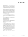
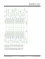
3.5.2 The Main Menu
The menu mode lets you view and change settings of the sat-nms LFTX/RX. From the display mode, you
enter the menu by pressing the
key. To leave the menu, repeatedly press the
key until the display
screen appears again. If there are no keystrokes for 2 minutes, the unit automatically leaves the menu and
returns to display mode.
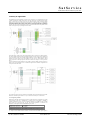
Depending if a slot is configured as a RX or TX slot, the structure changes in some parameters. The
following diagrams shows both possibilities (Slot 1 -> RX, Slot 2 -> TX).
The menu structure depends also if the chassis is configured in single or in master/slave mode. The structure
is shown in the two diagrams below. The first one shows the menu structure of a single unit, the second
shows the structure of a master/slave unit.
(C) 2013, SatService GmbH
www.satnms.com
LF-UM-1301 Page 15/28
SatService
Gesellschaft für Kommunikationssysteme mbH
T he FAULT sub menu shows you the state of every slot. The MEASUREMENT sub menu gives an
overview over the actual measurement values for every slot. The SETTINGS sub menu lets you view and
modify the operational parameters of the LFTX/RX. The SETUP sub menu contains a number of
parameters which usually only need to be changed during the installation of the optical link.
For further information about the parameters see the chapters Operational Parameters and Installation
Parameters of this manual.
To navigate in the menu, use the
the selected menu branch. Pressing
display mode.
or
keys to select a sub menu, then press
to descend in
ones returns to the main menu level, pressing it twice returns to
3.5.3 Editing Numeric Parameters
To change a numeric parameter like the the RF offset, select this value from the SETTINGS menu. The
upper display display line describes the parameter, the lower line shows it's value:
To set a new value, press
. This clears all figures from the value display and shows '>_' at the first
column to signal the editing mode.
Using the number keys, you enter the new value. The digits fill the entry field from right to left, like with a
pocket calculator. The
keys enable you to write a ‚dot' or a ‚minus'. The
key may be used to
delete the last digit.
To accept the edited value, press
. This checks the entered value against it's limits and executes the
parameter change. Pressing
twice (the first key press clears the display) leaves the editing mode without
changing anything.
3.5.4 Editing Multiple Choice Parameters
To change a numeric parameter like the RS232 interface baud rate, select this value from the SETTINGS
menu. The upper display line describes the parameter, the lower line shows it's value:
To set a new value, press
column. Use the
or
. This changes to the editing mode, signaled by a '>' character in the first
keys to change the value.
To accept the changed value, press
. Pressing
leaves the editing mode without changing the value.
3.5.5 Fault Display
The fault display page lets you view the actual state of all fault flags and also the latches state of these flags.
From the main menu, select FAULTS and press
by a 2-character memnotic.
to see the faults display. The fault states are represented
label description
OK
Parameter ok
WN
Warning state
(C) 2013, SatService GmbH
www.satnms.com
LF-UM-1301 Page 16/28
SatService
Gesellschaft für Kommunikationssysteme mbH
AL
Alarm state, parameter out of range
The example below shows two examples of a faults display page.
The first example shows the Fault Display of a LXRX card. The following parameters are shown:
Parameter Description
SLOT 1
Number of the slot, which faults are shown actually
OpP
Optical input power state, here an alarm is displayed
RFP
State of the RF output power, here an alarm is displayed
THR
Shows, if the RF power is in range of the user-defined threshold, here an ok state is
displayed.
The second example shows the Fault Display of a LFTX card. The following parameters are shown:
Parameter Description
SLOT 2
Number of the slot, which faults are shown actually
LsD
Shows, if the laser diode is working, here an alarm is displayed
RFP
State of the RF input power, here a warning is shown
LNC
Shows, if power consumption of the LNC is within the user-defined range. Here an ok state
is displayed.
If no card is placed to a slot, only *empty* is displayed in the fault menu.
When you press the
key during the LFTX/RX shows the fault state of a slot, you will be ask whether
to reset the latched faults. To acknowledge this, press
. To leave the fault display without resetting the
latched faults, press
.
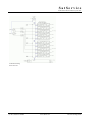
3.5.6 Local operation LFRX Card
The following picture shows you the front view of a LFRX card.
Depending on the card configuration, the 'Opto In' connector is an E2000 or a FC/APC connector. Connect
here the optical fiber which signal should be received.
The following indicator LED's are located on the cards front panel:
Name Description
PD
This (green) LED shows the state of the receive pin-diode. The LED turns on, if there is an
optical input connected to this card.
PS
The (green) PS-LED displays the power supply state of the card. The LED is on, if the power
supply of the card is working.
Max
The (yellow) Max-LED turns on, if the optical input power is below the recommended level.
Min
The (yellow) Min-LED turns on, if the optical input power is above the recommended level.
You have the possibility to change the following parameters:
Parameter Description
Gain
An integrated attenuator makes is possible to attenuate the RF-output-signal in 1dB-steps
from 0 to 31dB. This switch has 16 steps. Use this switch to select the attenuation range to 0
…15dB or 16…31dB.
0..15
By setting this switch, you define the range of attenuation, that can be set by the gain switch.
I n the 0 position, it is possible to set the attenuator from 0…15dB, in the 15 position, the
attenuation value can be set from 16…31dB.
RM..LC
This DIP-switch defines, if the card is controlled remote RM or local LC. If the switch is in
the LC position, it is not possible, to change the parameters of this card via remote Inferface
(IP, RS232, SNMP) or via the front panel keyboard of the LFTX/RX chassis.
Additionally you can measure the following parameters:
Parameter Description
T P o u t - The testport gives you the opportunity to measure the RF-Level on the Front panel. The
10dB
Signal, that you can measure here is about 10dB lower than the output signal on the back
side of the LFTX/RX chassis
PWR
Here you can measure the level of the RF power. The scaling is 50mV/dB
GND
Reference Ground for the PWR measurement.
GND
Reference Ground fort he PDP measurement
PDP
Here you can measure the optical input power. 100mV relates to 100uW.
(C) 2013, SatService GmbH
www.satnms.com
LF-UM-1301 Page 17/28
SatService
Gesellschaft für Kommunikationssysteme mbH
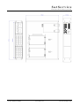
3.5.7 Local operation LFTX Card
The following picture shows you the front view of a LFTX card.
Depending on the card configuration, the 'Opto Out' connector is an E2000 or a FC/APC connector.
Connect here the optical fiber to transmit the optical signal.
The following indicator LED's are located on the cards front panel:
Parameter Description
LD
This (green) LED shows the state of the TX laser diode. The LED turns on, if the laser diode
is working.
PS
The (green) PS-LED displays the power supply state of the card. The LED is on, if the
power supply of the card is working.
Max
The (yellow) Max-LED turns on, if the RF input level is below the recommended level.
Min
The (yellow) Max-LED turns on, if the RF input level is above the recommended level.
You have the possibility to change the following parameters:
Parameter Description
Gain
An integrated attenuator makes is possible to attenuate the RF-input-signal in 1dB-steps from
0 to 31dB. This switch has 16 steps. Use the 0..15 switch to select the attenuation range to 0
…15dB or 16…31dB.
0..15
By setting this switch, you define the range of attenuation, that can be set by the gain switch.
In the 0 position, it is possible to set the attenuator from 0…15dB, in the 15 position, the
attenuation value can be set from 16…31dB.
0..DC
If your card is equipped with this functionality, you can switch here the 15VDC on and off
to supply a LNC connected to the RF in of this slot. In the 0 position of the switch, 15VDC
is off, in the DC position, the 15VDC is on.
RM/LC
This DIP-switch defines, if the card is controlled remote RM or local LC. If the switch is in
the LC position, it is not possible, to change the parameters of this card via remote Inferface
(IP, RS232, SNMP) or via the front panel keyboard of the LFTX/RX chassis.
Additionally you can measure the following parameters:
Parameter Description
TPout
10dB
- The testport gives you the opportunity to measure the RF-Level on the Front panel. The
Signal, that you can measure here is about 10dB lower than the output signal on the back
side of the LFTX/RX chassis.
PWR
Here you can measure the level of the RF power. The scaling is 50mV/dB
GND
Reference Ground for the PWR, LDC and LDP measurement.
LDC
Here you can measure the current consumption of the laser diode. 100mV relates to 10mA.
LDP
Here you can measure the optical power. 100mV relates to 100uW.
(C) 2013, SatService GmbH
www.satnms.com
LF-UM-1301 Page 18/28
SatService
Gesellschaft für Kommunikationssysteme mbH
4 Remote Control
T he sat-nms LFTX/RX L-Band Optical Link chassis may be controlled remotely by a monitoring and
control application either through the TCP/IP interface or through a serial RS232 interface. Both
communication methods use the same commands and parameters, however, there are different frames
around each message depending communication method used. The third method is SNMP.
Controlling the device from the web interface, the TCP/IP remote control interface, the SNMP interface or
via the serial interface is completely equal, commands may sent to any interface at any time, the LFTX/RX
will use the parameter it receives last.
4.1 General command syntax
The LFTX/RX knows a number of parameters, each identified by a parameter name. To set a certain
parameter to a new value, a message:
name=value
has to be sent to the device. The LFTX/RX interprets this command, checks the range of value, sets the
internal parameter and then answers:
name=value
T he value in the reply is the value actually recognized by the device. For instance, if the requested value
was out of range, the replied (and internally used) value is limited to the applicable minimum or maximum.
To read a parameter from the LFTX/RX, instead of a new parameter value a question mark is sent:
name=?
The device replies the actual value in a complete message:
name=value
A complete list of the parameter the sat-nms LFTX/RX knows is shown later in this document in chapter
Parameter list. Below, some common rules applying to the remote control message syntax are summarized.
Parameter names always are of lower case letters, most of them are four characters long.
Non-numeric parameter values always are written in upper case.
Numeric (floating point) values may be specified with an arbitrary precision, however the device will
reply only a fixed number of places. The LFTX/RX recognizes a decimal point ('.'), numbers must not
contain any commas.
There must not be any whitespace in front or after the '=' in a message.
If the command/query is not of the form name=value or name=?, the LFTX/RX replies the message
?SYNTAX.
If the message syntax is OK, but contains an unknown parameter name is used, the reply is ?
UNKNOWN
Numeric parameters are cut to the limits defined for this particular parameter.
Misspelled choice values cause the LFTX/RX to set the first value of the choice list.
Assigning a value to a read-only parameter will cause no fault, however the LFTX/RX will overwrite
this parameter immediately or some seconds later with the actual value.
4.2 The TCP/IP remote control interface
Controlling the sat-nms LFTX/RX Optical Links through the network is done by means of HTTP GET
requests. Setting parameter values or querying readings or settings, all is done by requesting HTTP
documents from the unit. The message to the LFTX/RX thereby is coded into the URL as a CGI form
parameter. The device replies a one line document of the MIME type 'text/plain'.
The document name for remote control is /rmt, hence (assuming the LFTX/RX is listening to the IP address
10.0.0.1), requesting a document with the URL
http://10.0.0.1/rmt?sver=?
will let the LFTX/RX reply the software version in a one line text document:
sver=1.012 2007-12-01
This way all parameters may be queried or set, you may use your favorite web browser to try out the
remote control of the LFTX/RX manually.
4.3 The RS232 remote control interface
Beside the network interface, the sat-nms LFTX/RX also provides an RS232 serial port which can be used
to control the device remotely. Depending on the device address set, the LFTX/RX either runs framed
protocol with start/stop characters and checksum or it provides a dumb terminal interface. The RS232
interface operates by default at 9600 baud, no parity, 8 data bits, one stop bit.
You can configure the baud rate on the front panel.
If an address 'A' .. 'G' is selected, the LFTX/RX expects each message it receives to be packed into a frame
as described below.
char # example description
1
{
start character, always '{'
2
A
device address (A..G)
3
t
first character of the message body
.
m
message body ...
.
p
..
.
0
..
.
=
..
n-1
?
last character of the message body
n
}
end character, always '}'
n+1
.
checksum
(C) 2013, SatService GmbH
www.satnms.com
LF-UM-1301 Page 19/28
SatService
Gesellschaft für Kommunikationssysteme mbH
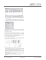
The checksum byte is calculated using an algorithm as implemented by the following formula:
This protocol type is known as MOD95- or Miteq protocol . The LFTX/RX also packs it's reply in a
protocol frame as described above. incomplete frames, checksum errors or address mismatches let the
device ignore the message. The time between the characters of a message must be less than 5 seconds or the
device will treat the message as incomplete.
If the LFTX/RX is set to the device address 'NONE', it uses a simple line protocol instead of the framed
protocol described above. Messages sent to the device have to be terminated with a carriage return character
(ASCII 13), the device terminates replies with a CR/LF pair (ASCII 13/10). There is no echo for characters
entered, hence this protocol easily may be used for computer based remote control.
4.4 SNMP Control
The sat-nms LFTX/RX contains an SNMP agent listening at UDP port 161. The SNMP agent provides a
common subset pf the MIB-II system / interface parameters and gives full access to the remote control
capabilities of the LFTX/RX with a number of MIB objects placed in the private.enterprises tree.
The actual MIB file defining the sat-nms LFTX/RX Optical Link private MIB may be downloaded from the
unit itself by FTP (user 'service', password 'service'). The file 'LFTXRX.MIB' contains all necessary
information. A link to this MIB file is also included in the web interface on the 'setup page'.
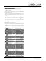
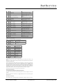
4.5 Parameter list
The table below shows the complete list of M&C parameters the sat-nms LFTX/RX chassis knows. For
each parameter the valid range and a short description is given.
If the LFTX/RX chassis is configured as single unit, use the commands which designated for the master
chassis. The commands for slave chassis are not valid.
In master/slave mode each chassis could give you all information for both units. So normally a M&C
system will communicate only with one chassis (e.g. the master) and gets all information about master and
slave from this unit.
Common status queries and commands
name
. range/format
description
addr
r/o
A,B,C,D,E,F,G,none
RS232 communication address
alrm
r/o
[see below]
Faults master chassis
alrs
r/o
[see below]
Faults slave chassis
atpm
r/o
[card1],..,[card10] : 0,1
Attenuator present for master chassis slots
(1=installed, 0=not installed)
atps
r/o
[card1],..,[card10] : 0,1
Attenuator present for slave chassis slots
(1=installed, 0=not installed)
attm
r/w
[card1],..,[card10] : 0..31
Attenuator settings in dB for master
chassis slots
atts
r/w
[card1],..,[card10] : 0..31
Attenuator settings in dB for slave chassis
slots
baud
r/o
DISABLED,9600,19200,38400,57600,115200 Interface baudrate
clft
o/w 1
Clear latched faults
diom
r/o
[card1],..,[card10] dB
Diode RF Offset for master chassis slots
dios
r/o
[card1],..,[card10] dB
Diode RF Offset for slave chassis slots
divm
r/o
[card1],..,[card10] dBm
Diode RF Power for master chassis slots
divs
r/o
[card1],..,[card10] dBm
Diode RF Power for slave chassis slots
lnbm
r/o
[card1],..,[card10] : OFF,ON
LNB DC supply for master chassis slots
lnbs
r/o
[card1],..,[card10] : OFF,ON
LNB DC supply for slave chassis slots
lnim
r/o
[card1],..,[card10] mA
LNB current minimum limit for master
chassis slots
lnis
r/o
[card1],..,[card10] mA
LNB current minimum limit for slave
chassis slots
lnvm
r/o
[card1],..,[card10] mA
LNB current for master chassis slots
lnvs
r/o
[card1],..,[card10] mA
LNB current for slave chassis slots
lnxm
r/o
[card1],..,[card10] mA
LNB current maximum limit for master
chassis slots
lnxs
r/o
[card1],..,[card10] mA
LNB current maximum limit for slave
chassis slots
notm
r/o
nots
r/o
nslm
r/o
[card1],..,[card05]
Description/Note left cards of the master
chassis
nsls
r/o
[card1],..,[card05]
Description/Note left cards of the master
chassis
nsrm
r/o
[card6],..,[card10]
Description/Note right cards of the master
chassis
nsrs
r/o
[card6],..,[card10]
Description/Note right cards of the master
chassis
plcm
r/o
[card1],..,[card10] : RX,TX,NONE
Card type of master chassis slots
plcs
r/o
[card1],..,[card10] : RX,TX,NONE
Card type of slave chassis slots
povm
r/o
[card1],..,[card10] uW
Optical input power (LFRX) or output
power (LFTX) of master chassis slots
povs
r/o
[card1],..,[card10] uW
Optical input power (LFRX) or output
Description/Note master chassis
Description/Note slave chassis
(C) 2013, SatService GmbH
www.satnms.com
LF-UM-1301 Page 20/28
SatService
Gesellschaft für Kommunikationssysteme mbH
power (LFTX) of slave chassis slots
rdlu
r/w
manual,auto,off
Redundancy setting card 1-5 (left)
rdru
r/w
manual,auto,off
Redundancy setting card 6-10 (right)
rdsw
r/w
0,1
Redundancy switched indication (1=has
switched, clear with set to 0)
redc
r/w
[card1],..,[card10] : YES,NO
Redundancy setting for each individual
slot/card
redd
r/o
none,intern,extern,intern2,extern2
Installed redundancy type / backplane
redl
r/w
1,2,4,5,NONE
Redundancy position of left slots
redr
r/w
6,7,9,10,NONE
Redundancy position of right slots
refr
r/o
1,3,5,10
Refresh Rate (secs)
remm r/o
[card1],..,[card10] 0,1
Remote (1) or Local (0) setting of each
card of master chassis
rems
r/o
[card1],..,[card10] 0,1
Remote (1) or Local (0) setting of each
card of slave chassis
rfom
r/o
[card1],..,[card10] dB
RF RF Offset for master chassis slots
rfos
r/o
[card1],..,[card10] dB
RF RF Offset for slave chassis slots
rfvm
r/o
[card1],..,[card10] dBm
RF Power for master chassis slots
rfvs
r/o
[card1],..,[card10] dBm
RF Power for slave chassis slots
snom
r/o
Device serial no master chassis
snos
r/o
Device serial no slave chassis
stim
o/w YYYY:MM:DD hh:mm:ss
Set date / time
svrm
r/o
Software version master chassis
svrs
r/o
thrm
r/w
[card1],..,[card10] dBm
RF Threshold for master chassis slots
thrs
r/w
[card1],..,[card10] dBm
RF Threshold for slave chassis slots
time
r/o
YYYY:MM:DD hh:mm:ss
Date / time
tmpm r/o
°C
Temperature master chassis
tmps
°C
Temperature slave chassis
Software version slave chassis
r/o
Master/Slave related commands
adex r/o
A,B,C,D,E,F,G,NONE Adr corresp. Chassis
coex r/o
HTTP,RS-232
Type of master/slave Communication
ipex
r/w aaa.bbb.ccc.ddd
IP corresp. Chassis
unit
r/w Master,Slave,Single
Chassis Type
SNMP related commands
sdes
r/o
SNMP System description
scon
r/w
SNMP System contact
snam
r/w
SNMP System name
sloc
r/w
SNMP System location
rcom
r/w
SNMP read community
wcom r/w
SNMP write community
tcom
r/w
SNMP trap community
autr
r/w enabled,disabled SNMP enable Auth traps
ipt1
r/w aaa.bbb.ccc.ddd
SNMP Trap IP 1
ipt2
r/w aaa.bbb.ccc.ddd
SNMP Trap IP 2
ipt3
r/w aaa.bbb.ccc.ddd
SNMP Trap IP 3
ipt4
r/w aaa.bbb.ccc.ddd
SNMP Trap IP 4
Fault Message
The commands 'alrm' and 'alrs' return a text string which shows the fault status of the master or slave
chassis.
Syntax: S[power supply faults]R[rf faults]O[optical faults]L[lnb faults]T[threshold faults]C[communication
fault][internal fault][switch fault]
The power supply faults list contains 2 characters for power supply 1 to 2. The rf faults , optical faults, lnb
faults and threshold faults lists contains 10 characters, representing the 10 slots of a sat-nms LFTX/RX
chassis. The communication fault contain 1 characters. The unit sets the fault if the communication to the
corresponding chassis is not possible. This fault flag is only valid, if the LFTX/RX chassis is configured for
master/slave mode. The internal fault shows that there is a problem with the internal communication
between different components of one sat-nms LFTX/RX chassis. The unit sets the switch fault if there are
problems with the internal or external (e.g. wave-guide} switches for the redundancy switching.
The meaning of the fault characters are: 0 means OK and 1 means FAULT.
http://192.168.2.81/rmt?alrm=?
alrm=S10R0000100001O0000000000L0000000000T0000000000C000
The example shows an master chassis, where the following alarms are active: power supply 1, rf fault of slot
5 and 10.
Please keep in mind, that not all slots have to be equipped with LFRX or LFTX cards and the empty slot
may show a fault.
Measurement and setting lists
Some commands returns a comma separated list of measurements or settings for all slots of a chassis. So
(C) 2013, SatService GmbH
www.satnms.com
LF-UM-1301 Page 21/28
SatService
Gesellschaft für Kommunikationssysteme mbH
you get 10 values at ones.
http://10.0.0.1/rmt?powm=?
This returns for each slot of the (master) chassis the optical power level. Empty slots are marked with -.
povm=-,-,1458,-,1466,-,-,1454,-,1454
Plugged/unplugged Cards
The commands 'plcm' and 'plcs' return a comma separeted list of the state of all boards.
http://10.0.0.1/rmt?plcm=?
This returns for each slot the configured card type. In this example are slot 1-5 are configured a receiver, 68 as transmitter and 9-10 are empty. Please keep in mind, that the LFTX/RX chassis does not detect what
kind of card is installed. The return value of the function shows you what the user has configured for each
slot.
plcm=RX,RX,RX,RX,RX,TX,TX,TX,NONE,NONE
master/slave mode
The following table shows the which parameters are available for LFRX and LFTX cards
Parameter
LFRX LFTX
description/note rx
RF Threshold
rx
Attenuator
rx
LNB Power
RF Power
tx
tx
rx
Diode Power
Optical Power
tx
tx
tx
rx
LNB Current
tx
tx
RF Fault
rx
tx
Optical Fault
rx
tx
LNB Fault
tx
Threshold Fault rx
(C) 2013, SatService GmbH
www.satnms.com
LF-UM-1301 Page 22/28
SatService
Gesellschaft für Kommunikationssysteme mbH
5 Theory of Operation
The sat-nms L-Band optical transmitters and receivers were developed to cover all applications in the field
of satellite communication, satellite ground stations, VSAT and cable networks. The following block diagram
shows a typical scenario of a teleport. The LNCs at the different antennas provide L-Band output signals
which have to be routed via long cable runs from the antennas to a central site, in this case a switch matrix.
The optical transmitter converts the analog L-Band spectrum (or any other RF spectrum in the specification
of the different modules) with the help of a laser diode to a optical output signal with a wavelength of
1310nm. This is the standard wavelength used by most of the laser diodes. But it is also possible to select
another wavelength on request by selecting another laser diode.
This example shows a satellite receive and transmit application with two antennas and at different locations,
but with one sat-nms LFTX/RX chassis which handles all signals from both antennas and the uplink signal
to the second antenna. In this case the satellite modulator delivers its L-Band or 70MHz signal to the optical
transmitter located for example in the central building and at the end of the optical fiber link a optical
receiver regenerates the RF signal spectrum which can be delivered for example to a block up-converter
(BUC).
As already explained in this TX application it is also possible to provide the 10MHz reference frequency for
the BUC via the same optical link. You can see in this block diagram also the redundant configuration of the
receive path from the first antenna.
The second block diagram show the combination of the sat-nms LSM L-Band Switch Matrix with the satnms LFRX L-Band Fiber Optical Receivers. So you use the LFRX card directly in our switch matrix.
5.1. Frequency bands
While the fiber optical links where designed by SatService GmbH mainly for the transmission of the satellite
L-Band frequency band (950 to 2150MHz) also a broadband version from 50MHz to 2150MHz is
available. So this link type can also be used to transmit the traditional 70 or 140MHz IF bands of satellite
ground stations and a microwave links. But also other terrestrial applications are feasible like the
transmission of GSM signals in the 800 and 1800MHz frequency bands.
sat-nms LFRX-L and LFTX-L
950 to 2150MHz
sat-nms LFRX-B and LFTX-B
50 to 2150MHz
sat-nms LFRX-10 and LFTX-10 950 to 2150MHz and 10MHz reference frequency for BUC
As a unique feature the sat-nms LFTX/RX modules can transmit L-Band and 10MHz signals together on
(C) 2013, SatService GmbH
www.satnms.com
LF-UM-1301 Page 23/28
SatService
Gesellschaft für Kommunikationssysteme mbH
one single fiber connection. This is a growing application for VSAT and satellite ground station transmit
chains which make use of Block Up-Converter (BUC). These BUCs very often need a 10MHz reference
frequency signal for their internal local oscillators. This is generated within the satellite modem and also
transmitted via the coaxial L-Band output.
T he sat-nms LFTX/RX fiber optical link can transmit this combined/multiplexed frequency signals. Each
fiber optical link (FOL) consists of two destinations which are interconnected via a fiber optical cable. On
one side of the link is the optical transmitter and on the other side is the optical receiver. Both modules are
Euro card sized (100x160mm) printed circuit boards which are plug into a 2U 19" chassis. The chassis
includes a redundant power supply, two backplanes to connect to the modules, an M&C printed circuit
board and at the front panel a keyboard and display as local user interface. Each chassis can contain 10 of
the optical link modules in any combination whether they are optical transmitters or receivers.
T he sat-nms LFTX/RX optical link is a broadband device and transmits transparently the complete RF
spectrum from one site to the other. All modulation formats, whether they are analog or digital, can be
transmitted transparently. The RF signal is directly modulated on to a high performance laser diode and adds
no phase noise or frequency instability to the original signal. The result is a very good signal quality.
Due to the very stable design of the optical transmitter and receiver electronics there is no need for an
Automatic Gain Control (AGC) within the circuits. So the link is compared to other vendor's solution really
transparent. Certainly a Manual Gain Control (MGC).function is included which can be also adjusted from
remote in a wide range of 30dB.
The optical transmitter module always provides also LNC supply voltage including current monitoring and
RF level detection.
We tried to realize all functionality in the baseline product so that you don't have to care about options. So
LNC powering and other features are always included wherever possible. This is only not the case in the
broadband and 10MHz boards as this makes no sense here in any case and the inductors of the LNC
voltage supply would destroy low frequency performance.
5.2 Connectors
For the optical interface SatService provides E2000 connectors from Diamond or Huber & Suhner by
default. But we are also in a position to deliver on request FC/APC or other single mode connectors. The
optical interface is located at the front panel of the 19" chassis because the optical patch panels are most
likely also at the front of a 19" rack. The connectors are slightly shifted back wards from the normal front
plane of the 19" drawer, so that they don't interfere at the front of the rack nor can they become destroyed
or snapped off.
5.3 Controller Module
The Controller Module of the sat-nms LFTX/RX is based on a separate 100x160mm printed circuit board.
It performs the following functions:
Monitor and control the optical transmitter cards LFTX
Monitor and Control the optical receiver cards LFRX
Manage the redundancy switching in master/slave mode
Control the keyboard and display at the unit
Control the Remote Interfaces (RS232 and LAN)
The design of the monitoring & control board is based on the same controller with integrated web server
which SatService has successfully used in all other products of the sat-nms family as well. The chip has the
following advantages:
Real Time Operation System with FTP, HTTP, SNMP over TCP/IP
Serial Interfaces
No external RAM and ROM components
10BaseT RJ45 Interface
5.4 Redundancy switching
A novel and additional feature of the sat-nms LFTX/RX system is the capability to switch complete optical
links and restore operation within a second if one of the optical links gets defective. This can effectively
increase the availability of optical transmission systems. In order to provide this feature the LFTX/RX
chassis can be equipped with a different internal back-plane which includes the necessary L-band switches
and the software with redundancy switching capability.
A common applications example is a connection of a Ku-Band antenna which normally provides 4 L-band
outputs from 4 LNCs (11/12GHz and Horizontal/Vertical) to a central building or a teleport. In this case a
5th module will be integrated in both the optical transmitter and the optical receiver chassis on both sides of
the link. All 5 links will be monitored and controlled via the M&C module in the master chassis. The two
M&C modules talk to each other via TCP/IP and one is the master module which initiates the redundancy
switching. The master module provides also the M&C information for the slave module so that the operator
does have all information available from both if he is in front of the units or if he operates the unit via the
web browser interface. If one optical link gets defective - for what ever reason, e.g. a faulty module or the
optical fiber cable is cut - the redundancy switching will be initiated in both chassis from the master M&C
module.
The redundancy switching capability is defined by the back plane in the sat-nms LFTX/RX chassis and how
the switches are route internally in the backplane. The principle is that the two columns are two separate
redundancy combinations which are internally interconnected by L-Band switches. So each column itself
will provide redundancy, where in slot 3 and 8 the redundant modules will be plugged.
This configuration will be defined in the setup page of the M&C software via the web browser interface. So
per 19" chassis with its maximum of 10 modules you can realize two independent redundancy
configurations.
(C) 2013, SatService GmbH
www.satnms.com
LF-UM-1301 Page 24/28
SatService
Gesellschaft für Kommunikationssysteme mbH
Another version provides the additional redundancy switching capability for external LNC. Based on the
standard chassis this unit contains also the necessary IO driver hardware card which drives a combination of
2/4 waveguide or coaxial switches for redundancy switching of the corresponding LNCs. The switchover
criteria is LNC current window. This unit provides a 2:1 protection. The external redundancy definition is
only available on request.
There is a second redundancy definition (intern2 and extern2). If you select this redundancy definition, the
left and the right redundancy combinations will be switched synchronous. For example if in the left column
slot 2 is switched to slot 3, then in the right column slot 7 is switched to slot 8. The behavior is the same for
extern2, but for an external device. The external redundancy definition is only available on request. On the
next picture you see an external redundancy definition but only with the Optical Transmitter.
(C) 2013, SatService GmbH
www.satnms.com
LF-UM-1301 Page 25/28
SatService
Gesellschaft für Kommunikationssysteme mbH
5.5 Outline Drawing
2 HU unit with 10 slots
(C) 2013, SatService GmbH
www.satnms.com
LF-UM-1301 Page 26/28
SatService
Gesellschaft für Kommunikationssysteme mbH
(C) 2013, SatService GmbH
www.satnms.com
LF-UM-1301 Page 27/28
SatService
Gesellschaft für Kommunikationssysteme mbH
6 Specifications
RF Specification
Frequency range
950 to 2150MHz or 50 to 2150MHz
L-Band Input Connectors (Transmitter)
SMA female 50Ohm or BNC female
75Ohm
L-Band Output Connector (Receiver)
SMA female 50Ohm or BNC female
75Ohm
L-band input test connector
SMA female 50 Ohm
L-band output test connector
SMA female 50 Ohm
Optical connectors
E2000 or FC/APC
Input Return Loss
> 17dB
Output Return Loss
> 17dB
Input Noise Figure
< 30dB
Gain (adjustable via local and remote interface)
+15 to -15dB in 1dB steps
Flatness
+/-1.5 dB, +/-0.25dB in any 40MHz
Input signal max (total level)
-10 dBm
Output Level max (total power)
-10dBm
Intermodulation at -13dBm Input Level
<-40 dBc
DC-output at L-band input connector
16+/-1V
M&C Interface Specification
Ethernet interface for M&C and user interface
10-Base-T, Via http GET requests
Front panel display
LCD 16x2
RS232 M&C Interface
D-SUB 9 female
Summary fault indication
Relay contact D-SUB 9 male
I/O output for external WG-switching (transmitter)
SUB-D 9 socket
Electrical and Mechanical Specification, Environmental
Conditions
Supply voltage
90 to 230V AC 50 to 60Hz
Connector for the two mains voltage AC input
IEC
Redundant power supplies
Hot swap capability available as an
option
Temperature range
-20 to + 50°C
Humidity
up to 90% non condensing
Mechanical size of mainframe
436 x 89 x 350 mm (WxHxD), 19"
2HU
(C) 2013, SatService GmbH
www.satnms.com
LF-UM-1301 Page 28/28