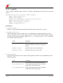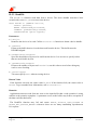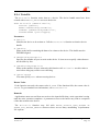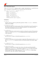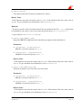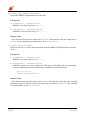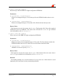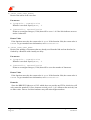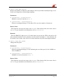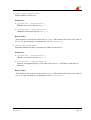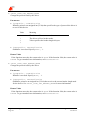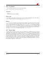
1
User’s Manual BBK-PCI light Ingenieurbüro für Elektronikdesign Ingo Mohnen Rottstraße 33 52068 Aachen Germany Tel: +49 (241) 94924-0 Fax: +49 (241) 94924-29 E-Mail: [email protected] WWW: http://members.aol.com/impaachen Document: Document No.: Date: File: BBK-PCI light Manual DC989001 September 21, 1998 bbklman.doc Scope This documentation refers to BBK-PCI light expansion card of revision 2.1 The BBK-PCI light device driver for Windows NT of revision 2.5 nd The 2 generation Iserver for Windows NT of IMP modification 1.0 The 2nd and 3rd generation Iservers of IMP modification 1.1 Copyrights And Warranties Ingo Mohnen & Partner GbR warrants the BBK-PCI light link interface and cabling against defects in materials and workmanship for a period of one year from the date of original retail purchase. This warranty does not apply if the product has been damaged by accident, abuse, misuse, or misapplication, has been modified without the written permission, or if the serial number has been removed or defaced. In no event will Ingo Mohnen & Partner GbR be liable for direct, indirect, special, incidental, or consequential damages resulting from any breach of warranty, or under any legal theory, including lost profits, downtime, goodwill, damage to or replacement of equipment and property, and any costs of recovering, reprogramming or reproducing any program or data used with BBK-PCI light. This manual and the software described in it are copyrighted with all rights reserved. Under the copyright laws, this manual or the software may not be copied, in whole or part without written consent of Ingo Mohnen & Partner GbR, except in the normal use of the software or to make a backup copy. The same proprietary and copyright notices must be affixed to any permitted copies as were affixed to the original. This exception does not allow copies to be made for others, whether or not sold, but all material purchased with all (with all backup copies) may be sold, given or loaned to another person. The main parts of Iserver are property of Inmos Limited. Ingenieurbüro Ingo Mohnen Page 2 BBK-PCI light User’s Manual Version 3.2 Table Of Contents I Hardware Description...............................................................................................................4 I.1 Introduction ...........................................................................................................................4 I.1.1 General Description............................................................................................................4 I.1.2 System Requirements .........................................................................................................4 I.1.3 Extent Of Supply ................................................................................................................5 I.1.4 Supported Link Standards ..................................................................................................5 I.1.5 Rear View ...........................................................................................................................6 I.2 Installation .............................................................................................................................8 I.3 BIOS Setup............................................................................................................................9 I.4 Troubleshooting.....................................................................................................................9 I.5 Technical Data.......................................................................................................................9 I.6 Connector Pinouts ...............................................................................................................10 I.6.1 Parsytec Link ....................................................................................................................10 I.6.2 Hema Link ........................................................................................................................10 I.6.3 MSC Link .........................................................................................................................11 II Using BBK-PCI light with Windows NT .............................................................................12 II.1 Driver Installation ..............................................................................................................12 II.2 Driver Deinstallation ..........................................................................................................13 II.3 Customizing the Driver ......................................................................................................13 II.4 Starting and Stopping the Driver........................................................................................14 II.5 Writing Your Own Programs Using the Driver .................................................................15 II.5.1 Introduction .....................................................................................................................15 II.5.2 CreateFile ........................................................................................................................16 II.5.3 ReadFile ..........................................................................................................................18 II.5.4 WriteFile..........................................................................................................................19 II.5.5 DeviceIoControl ..............................................................................................................20 II.5.6 CloseHandle ....................................................................................................................31 II.5.7 Header Mode ...................................................................................................................31 II.6 Using The Modified Iserver For Windows NT ..................................................................32 II.7 Troubleshooting .................................................................................................................32 III Using BBK-PCI light with DOS..........................................................................................33 III.1 Software Installation .........................................................................................................33 III.2 Using The Upgraded Iserver For DOS .............................................................................33 III.3 Using Software Designed For B004 Compatible Interfaces.............................................34 III.4 The Program PCICONF....................................................................................................34 III.4.1 Explicitly Define Assignments ......................................................................................35 III.4.2 Allow PCICONF To Use A Default Assignment ..........................................................35 III.5 Using BBK-PCI light With Windows 3.x ........................................................................37 III.6 Troubleshooting ................................................................................................................37 BBK-PCI light User’s Manual Version 3.2 Ingenieurbüro Ingo Mohnen Page 3 I Hardware Description I.1 Introduction I.1.1 General Description Thank you for choosing the BBK-PCI light as your OS link interface. You are now owner of a highly developed interface that performs interfacing between OS transputer links and a high performance PCI Bus that can be found in many computers nowadays. The BBK-PCI light is the first transputer link interface for the PCI Bus. Due to the high bandwith supplied by this bus system, a transputer link can be interfaced to a host computer very efficiently. The BBK-PCI light supplies you with the maximum data transfer rate that can be achieved using a C011/C012 link interface chip. Since in its master mode the board is capable of performing DMA transfers, the host CPU remains mostly unloaded by data transfers. This is especially important in today’s multitasking environments like Windows NT. Moreover, BBK-PCI light can be used in conjunction with software designed for Inmos’ B004 and compatible boards. The BBK-PCI light offers many sophisticated features: DMA capable, thus allowing maximum speed with only a nominal CPU load full duplex operation with Windows NT driver interrupt-controlled operation supported opto-isolated link (optional) fully software configurable as necessary for plug-and-play systems link speed is software switchable between 10 Mbps and 20 Mbps software upgrade for Inmos 2nd and 3rd gen. Toolset included supports several different OS link standards allows power supply of external devices, thus avoiding the need for an extra power supply for small peripherals I.1.2 System Requirements The upgraded Iservers require an IBM AT/386/486/Pentium or compatible PC running MS-DOS of revision 3.3 or higher. The driver for Windows NT requires a uniprocessor i386 architecture machine running Microsoft Windows NT 3.51. In either case the computer must be equipped with a bus complying to PCI specification rev. 2.0 and at least one idle PCI master slot. Ingenieurbüro Ingo Mohnen Page 4 BBK-PCI light User’s Manual Version 3.2 I.1.3 Extent Of Supply Before using this product, please carefully check that your package includes: BBK-PCI light link interface 3.5" supplemental disk User’s manual I.1.4 Supported Link Standards The BBK-PCI light supports most common OS link standards: Parsytec UniLink 9 pin Sub-D Hema link 25 pin Sub-D MSC link The Hema and MSC link connectors offer the ability to supply power to peripheral devices. Please refer to the section ‘Technical Data’ for maximum current load. BBK-PCI light User’s Manual Version 3.2 Ingenieurbüro Ingo Mohnen Page 5 I.1.5 Rear View The illustration below shows the Hema version of BBK-PCI light as an example. Please note that the Parsytec version does not support supplying current to external devices and hence the external power switch and external power supply indicator are omitted. External Power Supply Switch External Power Supply Indicator High Link Speed Indicator Link Error Indicator Master Mode Indicator Link Reset Indicator Rear View The external power supply switch is used to turn the 5V supply on Hema and MSC link connectors on and off by means of a small screwdriver. The red power supply indicator lights when power is turned on. Ingenieurbüro Ingo Mohnen Page 6 BBK-PCI light User’s Manual Version 3.2 Caution ! Be careful when linking to a system which supplies its own power to the link connector. In this case you must switch off either of the power supply connections unless you use a link cable which does not provide power supply, the latter being the safer method. The yellow high link speed indicator tells you that software selected 20 Mbps for link speed. The red link error indicator lights when the connected transputer system asserts the error line. The green master mode indicator is activated each time BBK-PCI light transfers data over the PCI Bus as a bus master. When operating in master mode this LED flashes rapidly. The red link reset indicator shows that the connected transputer system is currently being reset. BBK-PCI light User’s Manual Version 3.2 Ingenieurbüro Ingo Mohnen Page 7 I.2 Installation Although the hardware installation procedure is fairly simple be aware of static electricity. Under the right conditions, static electricity will build up. If you touch the board or its components it will discharge into the components and circuitry. Computer components are sensitive to damage from electrostatic discharge. They can be damaged or destroyed if the discharge is powerful enough. Static build-up is most likely to occur in dryer and cooler conditions, but it is always important to be cautious. To protect the link interface and other components against damage from electrostatic discharge, you should follow some basic precautions whenever you handle them: 1. Use a grounding wrist strap. The strap will have an ‘alligator’ clip at the end of a shielded wire lead. Clip it to a grounded object. Any static electricity will then harmlessly discharge through the strap. Put on and connect the strap before you handle the components. 2. Use an anti-static pad. Put any components on the pad whenever you work on them outside the computer. If you don’t have a pad, use the anti-static bag BBK-PCI light came in. Both the wrist strap and pad are inexpensive and are generally available from computer supply companies. After having taken the precautions outlined above please follow the steps outlined below in order to mount the BBK-PCI light in your computer. BBK-PCI light does not have any jumpers that have to be set, because the board is fully software configurable. You should consult your motherboard’s manual during hardware installation. 1. Switch off the machine and disconnect the power cord from the mains. 2. Open the computer’s case. 3. Determine an idle PCI slot into which BBK-PCI light shall go, which has to be a master slot. Not all PCI slots are necessarily master slots. There are motherboards where you have to explicitly enable a slot’s bus master capability in the BIOS setup. All other slot requirements demanded by BBK-PCI light are met if it mechanically fits into the slot connector. 4. Remove the slot cover from the slot you plan to use with BBK-PCI light. Put the screw aside and store the slot cover in a safe place in case you need it later. 5. Align the board’s edge connector to the slot connector and gently push BBK-PCI light into place. Do not use excessive force, it should insert easily. 6. Attach BBK-PCI light’s mounting bracket to the computer case using the mounting screw you put aside earlier. 7. Shut the computer’s case. 8. Connect the power cord to the mains, plug in your transputer’s link connector. 9. Start the system and change the BIOS setup. Ingenieurbüro Ingo Mohnen Page 8 BBK-PCI light User’s Manual Version 3.2 I.3 BIOS Setup The computer’s BIOS needs to be set up correctly in order to make hardware and software work properly. Unfortunately, the options provided by different BIOS manufacturers differ significantly, making it impossible to give detailed explanations for specific boards. The interrupt mapping for PCI devices is usually done automatically by the BIOS and should work without user intervention on PCI-only boards. If the board has additional ISA or EISA slots, the BIOS must be manually informed about the interrupt lines that will be used by ISA or EISA boards. Otherwise an inadverted interrupt sharing between ISA boards and PCI boards may occur, preventing the BBK-PCI light driver from starting because it can not allocate its interrupt line. Enabling PCI Concurrency allows the CPU to operate while the PCI bus is active. If this is not enabled, the CPU will experience a performance loss during data transfers. PCI Streaming or CPU to PCI burst both determine whether CPU bursts will be split up into multiple accesses on the PCI bus. This parameter is not particularly important for this driver, but it may improve overall system performance somewhat if enabled. PCI bursts should be enabled if possible to minimize PCI bus load. The PCI Latency Timer determines the possible length of PCI bursts. Longer bursts will result in higher PCI throughput. It should not be set to less than 10 for a BBK-PCI light. The BBK-PCI light needs to become bus master. Make sure it is placed in a slot with bus master capability and enable it if necessary. I.4 Troubleshooting Common pitfalls are: Physical connection incorrect or damaged The link speeds on either side of the link do not match I.5 Technical Data DC supply voltage Card type Size Power consumption Operating temperature Rel. humidity Storage temperature Links External power supply output (Hema/MSC only) BBK-PCI light User’s Manual Version 3.2 5 V ± 5% PCI Bus rev. 2.0 expansion card 5V, 32-bit, bus master 4.8" × 4.2" 4W 0 – 40 °C 20 – 80%, non-condensing 0 – 70 °C OS link 10 / 20 Mb/s 5V / 500mA Ingenieurbüro Ingo Mohnen Page 9 I.6 Connector Pinouts The following pages show all the connector pinouts for BBK-PCI light. The link connector used depends on the type of BBK-PCI light you have. Readily made link cables can be obtained from us, if you specify your requirements. Please contact us. I.6.1 Parsytec Link NC 1 ResetOut+ 8 NC 2 7 LinkIn+ ResetOut- 3 6 LinkIn- LinkOut+ 4 5 LinkOut- front view Lemosa EPG.1B.308.HLN Parsytec Link Connector The matching cable connector is the Lemo FGG.1B.308.CLAD. It can be ordered from Lemo Elektronik GmbH Stahlgruberring 7 81829 München Germany Phone +49 (89) 42 30 85 Fax +49 (89) 4 20 21 92 I.6.2 Hema Link LinkOut- 9 notError 8 LinkIn- 7 notReset 6 5 Vcc 4 LinkOut+ 3 notAnalyse 2 LinkIn+ 1 Gnd front view Sub-D 9 female Hema Link Connector Ingenieurbüro Ingo Mohnen Page 10 BBK-PCI light User’s Manual Version 3.2 I.6.3 MSC Link 13 Vcc Vcc 25 12 Vcc Vcc 24 11 NC NC 23 10 LinkOut+ LinkOut- 22 LinkIn- 21 NC 20 NC 19 notReset- 18 notAnalyse- 17 notError- 16 Gnd 15 Gnd 14 9 LinkIn+ 8 NC 7 NC 6 notReset+ 5 notAnalyse+ 4 notError+ 3 NC 2 Gnd 1 Gnd front view Sub-D 25 female MSC Link Connector BBK-PCI light User’s Manual Version 3.2 Ingenieurbüro Ingo Mohnen Page 11 II Using BBK-PCI light with Windows NT II.1 Driver Installation At this point you will need the supplemental disk. The contents of the directories relevant to the Windows NT driver installation are described here. DOC README.TXT TRANSP BLKTST.BTL NT DRIVER REGINI.EXE LINK.H BBKPCIL.INI BBKPCIL.SYS ISERVER.2G ISERVER.EXE SOURCE SAMPLES IOCTL.C IOCTL.EXE PEEK.C PEEK.EXE POKE.C POKE.EXE Latest documentation not contained here Block transfer test bootable This program sets up the registry using the data supplied in the file BBKPCIL.INI C Header file containing definitions needed to compile programs accessing the driver Registry default values The driver executable 2nd generation Iserver for Windows NT Directory containing the Iserver source files Sample application: ioctl call Sample application: peek transputer Sample application: poke transputer To install the new driver on a computer running Windows NT administrator rights are required. Perform these steps: 1. Make a backup copy of the supplemental disk, if you have not done so yet. 2. From a command prompt change your working directory to \NT\DRIVER on the supplemental disk and run the command regini bbkpcil.ini This sets up new registry values needed by NT and the driver. 3. Do copy bbkpcil.sys %SystemRoot%\system32\drivers This copies the driver executable to the Windows directory. 4. Reboot the machine. Ingenieurbüro Ingo Mohnen Page 12 BBK-PCI light User’s Manual Version 3.2 II.2 Driver Deinstallation To remove this driver from the system, you need to remove the driver executable file %SystemRoot%\system32\drivers\bbkpcil.sys You also need to remove all registry entries that belong to this driver. Remove HKEY_LOCAL_MACHINE/ SYSTEM/ CurrentControlSet/ Services/ bbkpcil and HKEY_LOCAL_MACHINE/ SYSTEM/ CurrentControlSet/ Services/ EventLog/ System/ bbkpcil using the Windows NT program regedt32. Having done this, the driver is completely removed from the system. II.3 Customizing the Driver The driver reads several values from registry on startup determining its behaviour at runtime. Some values may be changed through ioctl functions at runtime, others may not. The installation procedure sets default values for all registry values. If you do not like these defaults, you may change them using the Windows NT program regedt32. This progam is part of Windows NT, just type regedt32 The values can be found under HKEY_LOCAL_MACHINE/ SYSTEM/ CurrentControlSet/ Services/ bbkpcil/ Parameters/ Devicen The BBK-PCI light driver uses these values: Name LatencyTimer BBK-PCI light User’s Manual Version 3.2 Meaning When set, the driver sets the latency timer of the board to the desired value. This should not be Ingenieurbüro Ingo Mohnen Page 13 neccessary except on boards with a buggy BIOS. DMA_Enabled You may specify 0 or 1. If this parameter is set to 1 or is missing, the driver will use PCI busmaster DMA for transferring data. Otherwise it will use programmed I/O which is significantly slower. ProcessHeader You may specify values 0 through 3. If this parameter is set to 0, the driver will use stream mode. If it is set to 1 through 3, header mode will be used. The value then specifies the desired header length. Default is to use stream mode. UseAVLHeaderMode The presence of this parameter instructs the driver that the AVL-style header mode is to be used when enabled by registry parameter ProcessHeader or an ioctl() call. LinkSpeed This parameter defines the link speed used by the driver. You may specify 10 (0xA) or 20 (0x14). the default is 20. PollRetry When transferring single bytes via PIO, the driver minimizes the overhead induced by interrupt handling by first polling the device as many times as specified by this parameter. If no character can be transferred after this, the driver sets up an interrupt. This parameter does usually not have to be changed. FifoRetry Same as PollRetry, but used when waiting for the PCI matchmaker FIFO becoming full or empty. Should also not be changed. Timeout This parameter specifies the timeout in milliseconds for link transfers. It defaults to 3 seconds. Note that changes you make will not take effect before the driver is started next time. II.4 Starting and Stopping the Driver Once the driver is installed on your system, it must also be started before you can use it. You can do this either by typing net start bbkpcil or by using the Control Panel/Devices. Select BBKPCIL and click the Start button. Note that the driver will refuse to start if it encounters any problems. See chapter “Troubleshooting” for more information. Ingenieurbüro Ingo Mohnen Page 14 BBK-PCI light User’s Manual Version 3.2 During the boot process, Windows NT can start drivers automatically. In order to have the BBK-PCI light driver started automatically, you need to change its startup type. This is done using the Control Panel/Devices. Select BBKPCIL and click the Startup button. Then select Automatic as the desired startup type. It is not recommended to change the startup type to automatic before having verified that the driver starts cleanly by starting the driver manually and checking whether Windows NT’s event viewer indicates any driver related problems. Unless the startup type is set to automatic, you have to start the driver manually each time the machine is rebooted. The driver can be stopped either by typing net stop bbkpcil or by using the Control Panel/Devices. Select BBKPCIL and click the Stop button. Note that it is not necessary to stop the driver before shutting down the machine. II.5 Writing Your Own Programs Using the Driver II.5.1 Introduction Windows NT supports a fairly generic interface to allow communication between user programs and device drivers. It uses the same function calls that are used to do file I/O. Devices are separated from common files by reserving a separate name space for them. A device name has the form \\.\NameIndex, with Name identifying the driver and Index identifying the specific device controlled by this driver. The Name that has to be specified to access the BBK-PCI light driver is pcil. Index is 1 for the first BBK-PCI light board installed, 2 for the second, and so on. Note that the C notation for a single backslash in a string is "\\", so the name of the first board becomes "\\\\.\\pcil1". If your program wants to perform driver specific I/O control functions using DeviceIoControl, it needs to include the file link.h. The BBK-PCI light driver supports full duplex operation. Each device may be opened by multiple threads simultaneously. Multiple threads may call ReadFile and WriteFile simultaneously. The driver serializes these calls maintaining full duplex operation. Calls to DeviceIoControl are also serialized, they are executed as soon as neither a read nor a write operation are pending. BBK-PCI light User’s Manual Version 3.2 Ingenieurbüro Ingo Mohnen Page 15 II.5.2 CreateFile The CreateFile function opens a device. It returns a handle that can be used to access the device. HANDLE CreateFile (LPCTSTR lpDeviceName, DWORD dwDesiredAccess, DWORD dwShareMode, LPSECURITY_ATTRIBUTES lpSecurityAttributes, DWORD dwCreationDistribution, DWORD dwFlagsAndAttributes, HANDLE hTemplateFile); Parameters lpDeviceName Points to a null-terminated string that specifies the name of the device to open. dwDesiredAccess Specifies the type of access to the device. An application can obtain read access, write access, read-write access, or device query access. You can use the following flag constants to build a value for this parameter. Both GENERIC_READ and GENERIC_WRITE must be set to obtain read-write access. Value Meaning 0 Allows an application to query device attributes without actually accessing the device GENERIC_READ Specifies read access to the device GENERIC_WRITE Specifies write access to the file dwShareMode Specifies how this device can be shared. This parameter must be some combination of the following values: Value Meaning 0 Prevents the device from being shared FILE_SHARE_READ Other open operations can be performed on the device for read access FILE_SHARE_WRITE Other open operations can be performed on the device for write access Ingenieurbüro Ingo Mohnen Page 16 BBK-PCI light User’s Manual Version 3.2 lpSecurityAttributes Is only meaningful for file systems. Specify NULL when opening devices. dwCreationDistribution You must specify OPEN_EXISTING when opening devices. dwFlagsAndAttributes You must specify 0 when opening devices. hTemplateFile You must specify NULL when opening devices. Return Value If the function succeeds, the return value is an open handle to the specified device. If the function fails, the return value is INVALID_HANDLE_VALUE. To get extended error information, call GetLastError. BBK-PCI light User’s Manual Version 3.2 Ingenieurbüro Ingo Mohnen Page 17 II.5.3 ReadFile The ReadFile function reads data from a device. The device handle must have been created with GENERIC_READ access to the device. BOOL ReadFile (HANDLE hDevice, LPVOID lpBuffer, DWORD nNumberOfBytesToRead, LPDWORD lpNumberOfBytesRead, LPOVERLAPPED lpOverlapped); Parameters hDevice Identifies the device to be read. Call the CreateFile function to obtain a device handle. lpBuffer Points to the buffer that receives the data read from the device. This buffer must be DWORD aligned. nNumberOfBytesToRead Specifies the number of bytes to be read from the device. It is an error to specify values that are not divisible by four. lpNumberOfBytesRead Points to the number of bytes read. ReadFile sets this value to zero before doing any work or error checking. lpOverlapped You must specify NULL when accessing devices. Return Value If the function succeeds, the return value is TRUE. If the function fails, the return value is FALSE. To get extended error information, call GetLastError. Remarks Applications must not read from nor write to the input buffer that a read operation is using until the read operation completes. A premature access to the buffer may lead to corruption of the data read into that buffer. The ReadFile function may fail and return ERROR_INVALID_USER_BUFFER or ERROR_NOT_ENOUGH_MEMORY whenever there are too many outstanding asynchronous I/O requests. Ingenieurbüro Ingo Mohnen Page 18 BBK-PCI light User’s Manual Version 3.2 II.5.4 WriteFile The WriteFile function writes data to a device. The device handle must have been created with GENERIC_WRITE access to the device. BOOL WriteFile (HANDLE hDevice, LPCVOID lpBuffer, DWORD nNumberOfBytesToWrite, LPDWORD lpNumberOfBytesWritten, LPOVERLAPPED lpOverlapped); Parameters hDevice Identifies the device to be written to. Call the CreateFile function to obtain a device handle. lpBuffer Points to the buffer containing the data to be written to the device. This buffer must be DWORD aligned. nNumberOfBytesToWrite Specifies the number of bytes to write to the device. It is an error to specify values that are not divisible by four. lpNumberOfBytesWritten Points to the number of bytes written by this function call. WriteFile sets this value to zero before doing any work or error checking. lpOverlapped You must specify NULL when accessing devices. Return Value If the function succeeds, the return value is TRUE. If the function fails, the return value is FALSE. To get extended error information, call GetLastError. Remarks Applications must not read from nor write to the input buffer that a write operation is using until the write operation completes. A premature access to the buffer may lead to corruption of the data written to the device. The WriteFile function may fail with ERROR_INVALID_USER_BUFFER or ERROR_NOT_ENOUGH_MEMORY whenever there are too many outstanding asynchronous I/O requests. BBK-PCI light User’s Manual Version 3.2 Ingenieurbüro Ingo Mohnen Page 19 II.5.5 DeviceIoControl The DeviceIoControl function sends a control code directly to a specified device driver, causing the corresponding device to perform the specified operation. BOOL DeviceIoControl (HANDLE hDevice, DWORD dwIoControlCode, LPVOID lpInBuffer, DWORD nInBufferSize, LPVOID lpOutBuffer, DWORD nOutBufferSize, LPDWORD lpBytesReturned, LPOVERLAPPED lpOverlapped); Parameters hDevice Handle to the device that is to perform the operation. Call the CreateFile function to obtain a device handle. dwIoControlCode Specifies the control code for the operation. This value identifies the specific operation to be performed and the type of device on which the operation is to be performed. Each device driver may define its own set of values. lpInBuffer Pointer to a buffer that contains the data required to perform the operation. This parameter can be NULL if the dwIoControlCode parameter specifies an operation that does not require input data. nInBufferSize Specifies the size, in bytes, of the buffer pointed to by lpInBuffer. lpOutBuffer Pointer to a buffer that receives the operation’s output data. This parameter can be NULL if the dwIoControlCode parameter specifies an operation that does not produce output data. nOutBufferSize Specifies the size, in bytes, of the buffer pointed to by lpOutBuffer. lpBytesReturned Pointer to a variable that receives the size, in bytes, of the data stored into the buffer pointed to by lpOutBuffer. This parameter cannot be NULL. Even when an operation produces no output data, and lpOutBuffer can be NULL, the DeviceIoControl function makes use of the variable pointed to by lpBytesReturned. After such an operation, the value of the variable is without meaning. Ingenieurbüro Ingo Mohnen Page 20 BBK-PCI light User’s Manual Version 3.2 lpOverlapped You must specify NULL when accessing device drivers. Return Value If the function succeeds, the return value is TRUE. If the function fails, the return value is FALSE. To get extended error information, call GetLastError. Remarks The driver specific values for dwIoControlCode are defined in the file link.h, which must be included by your source code if you want to perform calls to DeviceIoControl. Legal values for dwIoControlCode are: IOCTL_LINK_RESET_LINK Resets the BBK-PCI light board, the link and any transputer node attached to it. Parameters lpInBuffer, nInBufferSize InBuffer is not used. Specify NULL, 0. lpOutBuffer, nOutBufferSize OutBuffer is not used. Specify NULL, 0. Return Value If the function succeeds, the return value is TRUE. If the function fails, the return value is FALSE. To get extended error information, call GetLastError. IOCTL_LINK_ANALYSE_LINK Performs an analyse reset. This also resets the board. Parameters lpInBuffer, nInBufferSize InBuffer is not used. Specify NULL, 0. lpOutBuffer, nOutBufferSize OutBuffer is not used. Specify NULL, 0. Return Value If the function succeeds, the return value is TRUE. If the function fails, the return value is FALSE. To get extended error information, call GetLastError. BBK-PCI light User’s Manual Version 3.2 Ingenieurbüro Ingo Mohnen Page 21 IOCTL_LINK_RESET_INTERFACE Resets the BBK-PCI light board but not the link. Parameters lpInBuffer, nInBufferSize InBuffer is not used. Specify NULL, 0. lpOutBuffer, nOutBufferSize OutBuffer is not used. Specify NULL, 0. Return Value If the function succeeds, the return value is TRUE. If the function fails, the return value is FALSE. To get extended error information, call GetLastError. IOCTL_LINK_GET_INFO Retrieves the driver revision and information about the BBK-PCI light hardware from the driver. Parameters lpInBuffer, nInBufferSize InBuffer is not used. Specify NULL, 0. lpOutBuffer, nOutBufferSize OutBuffer points to an array of characters. This array will be filled with a \0-terminated C-string containing the desired information. OutBuffer could look like this: driver V2.0\n serno E00000000023\0 Return Value If the function succeeds, the return value is TRUE. The function fails if the caller supplied insufficient space to hold the string. The return value will then be FALSE. To get extended error information, call GetLastError. Ingenieurbüro Ingo Mohnen Page 22 BBK-PCI light User’s Manual Version 3.2 IOCTL_LINK_GET_CONFIG Read one byte from the BBK-PCI light configuration EEPROM. Parameters lpInBuffer, nInBufferSize Points to an unsigned integer (32 bit) that specifies the EEPROM address that is to be read. lpOutBuffer, nOutBufferSize Points to an unsigned integer (32 bit) that will be filled with the data byte read. Return Value If the function succeeds, the return value is TRUE. The function fails if the caller supplied insufficient space for OutBuffer. The return value will then be FALSE. To get extended error information, call GetLastError. IOCTL_LINK_SET_CONFIG Write one byte to the BBK-PCI light configuration EEPROM. Parameters lpInBuffer, nInBufferSize Points to an array of two unsigned integers (32 bit each). The first element contains the EEPROM address that is to be written, the second element contains the data. lpOutBuffer, nOutBufferSize OutBuffer is not used. Specify NULL, 0. Return Value If the function succeeds, the return value is TRUE. If the function fails, the return value is FALSE. To get extended error information, call GetLastError. Remarks You should probably never use this function. If you do, take care. If the function is used improperly, the board may become permanently unusable. BBK-PCI light User’s Manual Version 3.2 Ingenieurbüro Ingo Mohnen Page 23 IOCTL_LINK_TEST_ERROR Retrieve the status of the error line. Parameters lpInBuffer, nInBufferSize InBuffer is not used. Specify NULL, 0. lpOutBuffer, nOutBufferSize Points to an unsigned integer (32 bit) that will be set to != 0 if the link indicates an error and to 0 otherwise. Return Value If the function succeeds, the return value is TRUE. If the function fails, the return value is FALSE. To get extended error information, call GetLastError. IOCTL_LINK_TEST_READ Retrieve the number of characters that are already read from the link and can therefore be fetched by a ReadFile with virtually no delay. Parameters lpInBuffer, nInBufferSize InBuffer is not used. Specify NULL, 0. lpOutBuffer, nOutBufferSize Points to an unsigned integer (32 bit) that will be set to the number of characters. Return Value If the function succeeds, the return value is TRUE. If the function fails, the return value is FALSE. To get extended error information, call GetLastError. Remarks Since the BBK-PCI light uses a C012 which does not provide any FIFOs, this driver will only return the numbers 0 (if no character arrived yet) or 1 (if a character has arrived), but no other value. Drivers for other hardware may still return higher numbers. Ingenieurbüro Ingo Mohnen Page 24 BBK-PCI light User’s Manual Version 3.2 IOCTL_LINK_TEST_WRITE Retrieve the number of characters the hardware will accept without actually having to wait for the receiving node to acknowledge anything. Parameters lpInBuffer, nInBufferSize InBuffer is not used. Specify NULL, 0. lpOutBuffer, nOutBufferSize Points to an unsigned integer (32 bit) that will be set to the number of characters. Return Value If the function succeeds, the return value is TRUE. If the function fails, the return value is FALSE. To get extended error information, call GetLastError. Remarks Since the BBK-PCI light uses a C012 which does not provide any FIFOs, this driver will only return the numbers 0 (if no character can be written currently) or 1 (if a character can be written), but no other value. Drivers for other hardware may still return higher numbers. IOCTL_LINK_SET_SPEED Change the link speed. Parameters lpInBuffer, nInBufferSize Points to an unsigned integer (32 bit) indicating the new link speed (10 for 10MBit/s or 20 for 20MBit/s). lpOutBuffer, nOutBufferSize OutBuffer is not used. Specify NULL, 0. Return Value If the function succeeds, the return value is TRUE. If the function fails, the return value is FALSE. To get extended error information, call GetLastError. BBK-PCI light User’s Manual Version 3.2 Ingenieurbüro Ingo Mohnen Page 25 IOCTL_LINK_GET_SPEED Retrieve the current link speed. Parameters lpInBuffer, nInBufferSize InBuffer is not used. Specify NULL, 0. lpOutBuffer, nOutBufferSize Points to an unsigned integer (32 bit) that will be set to the link speed (10 for 10MBit/s and 20 for 20MBit/s). Return Value If the function succeeds, the return value is TRUE. If the function fails, the return value is FALSE. To get extended error information, call GetLastError. IOCTL_LINK_ENABLE_DMA Enable DMA for this device. Parameters lpInBuffer, nInBufferSize InBuffer is not used. Specify NULL, 0. lpOutBuffer, nOutBufferSize OutBuffer is not used. Specify NULL, 0. Return Value If the function succeeds, the return value is TRUE. If the function fails, the return value is FALSE. To get extended error information, call GetLastError. Ingenieurbüro Ingo Mohnen Page 26 BBK-PCI light User’s Manual Version 3.2 IOCTL_LINK_DISABLE_DMA Disable DMA for this device. Parameters lpInBuffer, nInBufferSize InBuffer is not used. Specify NULL, 0. lpOutBuffer, nOutBufferSize OutBuffer is not used. Specify NULL, 0. Return Value If the function succeeds, the return value is TRUE. If the function fails, the return value is FALSE. To get extended error information, call GetLastError. IOCTL_LINK_TEST_DMA Determine whether the driver currently uses DMA for this device. Parameters lpInBuffer, nInBufferSize InBuffer is not used. Specify NULL, 0. lpOutBuffer, nOutBufferSize Points to an unsigned integer (32 bit) that will be set to != 0 if DMA is used and to 0 otherwise. Return Value If the function succeeds, the return value is TRUE. If the function fails, the return value is FALSE. To get extended error information, call GetLastError. BBK-PCI light User’s Manual Version 3.2 Ingenieurbüro Ingo Mohnen Page 27 IOCTL_LINK_SET_TIMEOUT Set the timeout value. Parameters lpInBuffer, nInBufferSize Points to an unsigned integer (32 bit) that indicates the desired timeout value in milliseconds. A timeout of 0 results in an indefinite wait. lpOutBuffer, nOutBufferSize OutBuffer is not used. Specify NULL, 0. Return Value If the function succeeds, the return value is TRUE. If the function fails, the return value is FALSE. To get extended error information, call GetLastError. IOCTL_LINK_GET_TIMEOUT Retrieve the current timeout value. Parameters lpInBuffer, nInBufferSize InBuffer is not used. Specify NULL, 0. lpOutBuffer, nOutBufferSize Points to an unsigned integer (32 bit) that will be set to the timeout value in milliseconds. Return Value If the function succeeds, the return value is TRUE. If the function fails, the return value is FALSE. To get extended error information, call GetLastError. Ingenieurbüro Ingo Mohnen Page 28 BBK-PCI light User’s Manual Version 3.2 IOCTL_LINK_SET_POLL_RETRY Set the parameter PollRetry. Parameters lpInBuffer, nInBufferSize Points to an unsigned integer (32 bit) that indicates the desired value. lpOutBuffer, nOutBufferSize OutBuffer is not used. Specify NULL, 0. Return Value If the function succeeds, the return value is TRUE. If the function fails, the return value is FALSE. To get extended error information, call GetLastError. IOCTL_LINK_SET_FIFO_RETRY Set the parameter FifoRetry. Parameters lpInBuffer, nInBufferSize Points to an unsigned integer (32 bit) that indicates the desired value. lpOutBuffer, nOutBufferSize OutBuffer is not used. Specify NULL, 0. Return Value If the function succeeds, the return value is TRUE. If the function fails, the return value is FALSE. To get extended error information, call GetLastError. BBK-PCI light User’s Manual Version 3.2 Ingenieurbüro Ingo Mohnen Page 29 IOCTL_LINK_SET_HEADER_MODE Change the protocol used by the driver. Parameters lpInBuffer, nInBufferSize InBuffer points to an unsigned int (32 bit) that specifies the type of protocol the driver is to use for this device. Value Meaning 0 The driver will use stream mode 1 2 3 The driver will use header mode. Value specifies the header length in bytes. lpOutBuffer, nOutBufferSize OutBuffer is not used. Specify NULL, 0. Return Value If the function succeeds, the return value is TRUE. If the function fails, the return value is FALSE. To get extended error information, call GetLastError. IOCTL_LINK_TEST_HEADER_MODE Change the protocol used by the driver. Parameters lpInBuffer, nInBufferSize InBuffer is not used. Specify NULL, 0. lpOutBuffer, nOutBufferSize OutBuffer points to an unsigned int (32 bit) that receives the current header length used for the device. See IOCTL_LINK_SET_HEADER_MODE for more information. Return Value If the function succeeds, the return value is TRUE. If the function fails, the return value is FALSE. To get extended error information, call GetLastError. Ingenieurbüro Ingo Mohnen Page 30 BBK-PCI light User’s Manual Version 3.2 II.5.6 CloseHandle The CloseHandle function closes an open object handle. BOOL CloseHandle (HANDLE hObject); Parameters hObject Identifies an open object handle. Return Value If the function succeeds, the return value is TRUE. If the function fails, the return value is FALSE. To get extended error information, call GetLastError. Remarks CloseHandle invalidates the specified object handle, decrements the object’s handle count, and performs object retention checks. Once the last handle to an object is closed, the object is removed from the operating system. Use CloseHandle to close handles returned by calls to the CreateFile function. Closing an invalid handle raises an exception. This includes closing a handle twice, not checking the return value and closing an invalid handle, and using CloseHandle on a handle returned by FindFirstFile. II.5.7 Header Mode During normal operation, the driver does not implement any additional protocol. The link simply looks like a stream device. Since OS links are very often used in conjunction with the ISERVER protocol defined by INMOS, this protocol was implemented into the driver, thereby reducing the number of driver calls needed for data transfers. The ISERVER protocol divides the data into variable size chunks. Each chunk of data is preceeded by a fixed length header containing the number of data bytes following. For ISERVER, the header is always 2 bytes long, allowing up to 64 KB of data in each block. For additional flexibility, the driver allows header lengths of 1, 2 and 3 bytes. BBK-PCI light User’s Manual Version 3.2 Ingenieurbüro Ingo Mohnen Page 31 II.6 Using The Modified Iserver For Windows NT On your supplemental disk there is an Iserver for the 2nd generation Inmos Toolset (\ISERVER.2G\ISERVER.EXE) which is modified for running in the Windows NT environment. This Iserver uses the BBK-PCI light driver for Windows NT or any other driver nd with the same interface and is not specifically tied to the hardware. Note that the 2 rd generation Iserver is capable of also serving bootables compiled with the 3 generation Inmos Toolset in most cases. In order to use the Iserver for Windows NT you should rename the original Iserver contained in the Inmos Toolset (usually in \ICTOOLS\ISERVER), e.g. to ISERVER.ORG and then copy the upgraded Iserver from the supplemental disk to the Toolset Iserver directory. You may alternatively choose to execute the Iserver for Windows NT from any other directory, provided this one is included in the standard execution PATH before the original Iserver directory. When invoking the Iserver for Windows NT the link name parameter gets the Windows NT device name of the link you intend to use, which in the case of BBK-PCI light is pciln with n being the current number of the BBK-PCI light installed in your computer, beginning at one. So for instance to boot the blocktest bootable from the first BBK-PCI light you type iserver /sl pcil1 /sb blktst.btl II.7 Troubleshooting Common errors that might occur are: The driver does not start The driver might not be able to detect a BBK-PCI light board or it might not be able to allocate resources (either port addresses or an interrupt). Ensure the board is properly seated and fixed in its slot. Also, the Windows NT event log might contain valuable information to solve this problem. The driver cannot be opened by applications Ensure the driver is started and you supplied the correct filename to CreateFile. The device can be opened, but data transfers always time out Timeouts occur if there was no interrupt after the specified time. This happens if the link connection is wrong or broken the link speeds do not match the other side does not accept data the PCI slot is not bus master capable The driver does not achieve the throughput it should This might indicate inappropriate PCI settings. Ingenieurbüro Ingo Mohnen Page 32 BBK-PCI light User’s Manual Version 3.2 III Using BBK-PCI light with DOS III.1 Software Installation In order to use BBK-PCI light with DOS, you should take a few additional steps. Basically, this involves copying some files from the supplemental disk to your hard disk. The following files are to be found on the supplemental disk: DOC README.TXT TRANSP BLKTST.BTL DOS ISERVER2.EXE ISERVER3.EXE CONNECT.DAT PCICONF.EXE PCIL.DAT Latest documentation not contained here Block transfer test bootable 2nd generation Iserver upgraded for BBK-PCI light 3rd generation Iserver upgraded for BBK-PCI light Sample connection database Configuration program for BBK-PCI light Sample configuration file 1. Make a backup copy of the supplemental disk, if you have not done so yet. 2. View the README.TXT file on the supplemental disk. 3. Create a directory with an arbitrary name, e.g.: md c:\bbkpcil 4. Copy at least the DOS and TRANSP directories from the supplemental disk to this directory: xcopy /S a:\DOS c:\bbkpcil xcopy /S a:\TRANSP c:\bbkpcil III.2 Using The Upgraded Iserver For DOS On your supplemental disk came an upgraded Iserver for 2nd generation Inmos Toolset called ISERVER2.EXE and another one for 3rd generation Inmos Toolset called ISERVER3.EXE. These Iservers use the bus master feature of the BBK-PCI light. They perform data transfers via bus mastering whenever possible and thus yield the highest data transfer rate achievable with BBK-PCI light under DOS. If you use one of these it is not necessary to configure your link interface manually since they automatically detect the base addresses that were assigned to the BBK-PCI light by the BIOS code during startup. BBK-PCI light User’s Manual Version 3.2 Ingenieurbüro Ingo Mohnen Page 33 In order to use our upgraded Iserver you should rename the original Iserver contained in the Inmos Toolset (usually in \ICTOOLS\ISERVER for 2nd generation and \D7314A\TOOLS for 3rd generation), e.g. to ISERVER.ORG and then copy the appropriate upgraded Iserver from the BBK-PCI light directory to the Toolset Iserver directory as ISERVER.EXE. You may alternatively choose to execute the upgraded Iservers from where they are, provided the directory you put them into is included in the standard execution PATH. When invoking the upgraded 2nd generation Iserver you must specify a link name of n,10|20[,r]. n is the current number of the BBK-PCI light installed in your computer, beginning at zero. 10|20 selects the link speed whereas r specifies to reset the adapter beforehand. So for instance to reset the interface and boot the blocktest bootable from the first BBK-PCI light with 20 Mbps you type iserver /sl 0,20,r /sb blktst.btl Our Iserver for 3rd generation Toolset relies on the connection database specified in the ICONDB environment variable as documented in the Inmos Toolset. A sample connection database named CONNECT.DAT is included on the supplemental disk. The linkdev field must contain pcil for BBK-PCI light, the address field holds the parameter n,10|20[,r] with the same function as explained above. Assumed you are using the entries from our sample CONNECT.DAT you would enter iserver /sl pcil1 /sb blktst.btl in order to boot BLKTST.BTL from the first BBK-PCI light. III.3 Using Software Designed For B004 Compatible Interfaces You can use existing software designed for Inmos B004 compatible boards without any change. Although it is not possible to make full use of all BBK-PCI light enhancements, you will still gain some performance against an original B004 link adapter. To use your existing software with the BBK-PCI light, the board has to be configured to use the same port addresses and link speed the B004 interface does. B004 boards are configured using jumpers. The BBK-PCI light does not have any jumpers. Instead, all configuration is done by software using the program PCICONF from the supplemental disk. This program allows you to individually configure your board according to your needs. The description of this program is given in the following section. III.4 The Program PCICONF In some cases you will have to configure your BBK-PCI light manually: Ingenieurbüro Ingo Mohnen Page 34 BBK-PCI light User’s Manual Version 3.2 If you want to use software written for B004 compatible boards If your mainboard’s BIOS does not properly configure PCI cards at startup Manual configuration is carried through by the PCICONF program you copied from the supplemental disk. It is invoked from the command line prompt by typing: PCICONF or PCICONF <filename> with <filename> specifying the name of a text file holding the desired configuration data. If <filename> is omitted, the program expects configuration data from stdin. A sample configuration file PCIL.DAT is included on the supplemental disk. It will configure BBK-PCI light for use with B004 compatible software. Since the configuration of PCI cards is not permanent, you have to redo the configuration each time the system is booted. It is therefore recommended to call PCICONF from your AUTOEXEC.BAT file. Remember leading the calling command line with the path to the PCICONF.EXE program or to add the path to the PATH environment variable. The configuration file is interpreted line by line, with each line containing one statement lead by a keyword. Possible keywords are: Keyword Meaning amcc <addr> Sets the base address for the PCI controller. The PCI controller uses 64 bytes of port space. In B004 compatible mode, this memory is not used, but you still have to make sure that this memory space does not cause any address conflicts. c012 <addr> Sets the base address for the C012 register set. This is a 4 bytes long area in port space. For B004 compatible operation, this should usually be 150h. ctrl <ctrl> Sets the base address for the control register set. This is a 4 bytes long area in port space. For B004 compatible operation, this should usually be 160h. speed 10|20 Sets the link speed. Legal values are 10 and 20, resulting in link speeds of 10 and 20 Mbps. device <slot> Specifies the PCI slot number of the BBK-PCI light the current set of configuration statements refers to. next Indicates that the following statements will refer to another BBK-PCI light and hence BBK-PCI light User’s Manual Version 3.2 Ingenieurbüro Ingo Mohnen Page 35 serves as a separator between multiple sets of configuration statements. You do not need this statement if there is only a single device present. Causes the remainder of the current line to be treated as a comment. # Numerical values as required by the amcc, c012 and ctrl keywords can be given in decimal, in octal with a leading 0 or hexadecimal with a leading 0x. Each of the three base addresses and the link speed have default values: amcc c012 ctrl speed 0xD000 0x0150 0x0160 10MBps If there is only a single BBK-PCI light you wish to configure for using B004 compatible addresses, the configuration file does not need to contain anything at all (it must exist though!). If you want other base addresses or link speeds, you need to specify the differing values in the configuration file. As long as there is only one BBK-PCI light device present in your computer, you do not need both the ‘device’ and the ‘next’ statements. If you have multiple devices, you need one separate set of configuration statements in the configuration file for each device that is to be configured. Each set must be separated by a ‘next’ statement. III.4.1 Explicitly Define Assignments By having one ‘device’ statement in each set of configuration statements, separated by ‘next’ statements, you can explicitly determine which BBK-PCI light will be configured using which set of statements. III.4.2 Allow PCICONF To Use A Default Assignment The default assignment is fairly simple: If omitting the ‘device’ statements the first configuration set corresponds to the BBK-PCI light located in the slot with the lowest number, the second set corresponds to the next higher slot number and so on. Usually you will have your configuration data stored in a file and you will specify the name of that file as a command line argument to PCICONF. Sometimes it might be appropriate to enter configuration data directly from stdin. In this case the program will be called without filename. You can then enter your configuration data after PCICONF has printed where it has found BBK-PCI lights. You terminate your entries with a Ctrl-Z character on a separate line. NOTE 1: Due to a limitation of the PCI interface used by the BBK-PCI light it is not possible to specify arbitrary values as base addresses. Instead, you can only use multiples of Ingenieurbüro Ingo Mohnen Page 36 BBK-PCI light User’s Manual Version 3.2 the region size (e.g. if a region is 64 bytes long, you can use only 0, 64, 128 etc. as base address values). NOTE 2: The PCICONF program does not check whether there are address conflicts with other devices in the system. The user of the program is fully responsible to make sure that no conflicts will occur. Otherwise none of the affected devices is likely to work properly. III.5 Using BBK-PCI light With Windows 3.x The bus master feature of the BBK-PCI light is currently not supported under Windows 3.x. It can only be used as a B004 compatible link interface instead. The process used to achieve this is quite similar to the one described in the corresponding section. You would call PCICONF first from any DOS prompt either before or after starting Windows. The B004 compatible software to use the link interface is then invoked as usual from a DOS prompt from within Windows. This might be the original Iserver or your favourite link software. III.6 Troubleshooting Common pitfalls are: The link speeds on either side of the link do not match Wrong configuration (when using the board as a B004 compatible link interface) The BIOS does not properly initialize BBK-PCI light’s PCI controller. Instead, you are thus required to use the PCICONF program in order to do so, which is described in the section ‘The Program PCICONF’. BBK-PCI light User’s Manual Version 3.2 Ingenieurbüro Ingo Mohnen Page 37