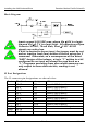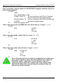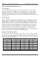
1
www.DanaherMotion.com
6420 Indexer/Drive
User Manual
MA6420
Rev C
Record of Manual Revisions
ISSUE
Date
Description of Revision
A
B
C
07/1992
07/1996
10/2003
Initial release
Updated corporate information
Updated corporate information
Copyright Information
© Copyright 1992 - 2003 Danaher Motion - All rights reserved.
Printed in the United States of America.
NOTICE:
Not for use or disclosure outside of Danaher Motion except under written agreement. All rights are
reserved. No part of this book shall be reproduced, stored in retrieval form, or transmitted by any
means, electronic, mechanical, photocopying, recording, or otherwise without the written permission
from the publisher. While every precaution has been taken in the preparation of the book, the
publisher assumes no responsibility for errors or omissions. Neither is any liability assumed for
damages resulting from the use of the information contained herein.
This document is proprietary information of Danaher Motion that is furnished for customer use
ONLY. No other uses are authorized without written permission of Danaher Motion. Information in
this document is subject to change without notice and does not represent a commitment on the part
of Danaher Motion. Therefore, information contained in this manual may be updated from time-totime due to product improvements, etc., and may not conform in every respect to former issues.
•
The safety-alert symbols used in this manual are:
Warning Alerts users to potential physical danger or harm. Failure to follow
warning notices could result in personal injury or death.
Caution Directs attention to general precautions, which if not followed, could result
in personal injury and/or equipment damage.
Note Highlights information critical to your understanding or use of the product.
Danaher Motion Pacific Scientific
Table of Contents
Table of Contents
1.
OVERVIEW OF 6420 INDEXER/DRIVE........................................... 1
1.1. 6420 DEFINITION...................................................................... 1
1.1.1. BLOCK DIAGRAM .............................................................. 2
1.1.2. FIXED RESOLUTION MODE ............................................. 2
1.1.3. VARIABLE RESOLUTION MODE ...................................... 3
1.2. DRIVE FEATURES .................................................................... 3
1.3. INDEXER FEATURES ............................................................... 4
1.4. SYSTEM COMPONENTS.......................................................... 4
1.5. WARRANTY............................................................................... 4
2.
INSTALLING THE 6420 INDEXER/DRIVE ....................................... 5
2.1. UNPACKING AND INSPECTING .............................................. 5
2.2. MOUNTING THE 6420 .............................................................. 5
2.2.1. MOUNTING DIMENSIONS................................................. 6
2.3. CONNECTING THE FOUR INPUT/OUTPUT CABLES ............ 6
2.3.1. CONNECTION DIAGRAM .................................................. 7
2.3.2. J3 MOTOR CONNECTION................................................. 7
2.3.2.1.
2.3.2.2.
2.3.2.3.
2.3.3.
2.3.4.
2.3.4.1.
2.3.4.2.
2.3.4.3.
2.3.5.
2.3.5.1.
2.3.5.2.
2.3.5.3.
4-Lead Motor Cable Requirements ..................................................... 8
8-Lead Motor, Series Connected......................................................... 9
8-Lead Motor, Parallel Connected .................................................... 10
J2 - POWER CONNECTION ............................................ 10
J4 - SERIAL PORT CONNECTION.................................. 11
Single-unit RS-232 Connection ........................................................ 12
Single-unit RS-422 Connection ........................................................ 12
Multi-unit RS-485 Connection.......................................................... 13
J5 - DISCRETE INPUTS/OUTPUTS CONNECTION....... 13
Dedicated Discrete Input/Output Lines............................................. 15
Input Interface Suggestions............................................................... 17
Output Interface Suggestions ............................................................ 18
2.4. USING THE 6420 TO CONTROL A 6410 DRIVE ................... 18
2.4.1. SYNCHRONOUS OPERATION ....................................... 19
2.4.2. ALTERNATING OPERATION .......................................... 19
2.5. FACTORY DEFAULT SETTINGS............................................ 19
2.5.1. DRIVE ............................................................................... 19
2.5.2. INDEXER .......................................................................... 20
2.5.3. DRIVE BOARD SETTINGS .............................................. 20
MA6420
Rev C
i
Table of Contents
2.5.4.
2.5.4.1.
3.
Jumper Settings................................................................................. 21
TESTING THE INSTALLATION............................................... 23
MAINTAINING\TROUBLESHOOTING............................................ 25
4.1.
4.2.
5.
INDEXER BOARD SETTINGS ......................................... 21
POWERING UP THE 6420 ............................................................. 23
3.1.
4.
Danaher Motion Pacific Scientific
MAINTAINING THE 6420 ........................................................ 25
TROUBLESHOOTING THE 6420............................................ 25
PROGRAMMING AND INSTRUCTION SET .................................. 27
5.1. IMMEDIATE MODE ................................................................. 27
5.2. EXECUTION MODE ................................................................ 28
5.3. THE AUTOSTART PROGRAM................................................ 28
5.4. INSTRUCTION OVERVIEW .................................................... 28
5.4.1. MOTION CONTROL ......................................................... 29
5.4.2. PROGRAM CONTROL..................................................... 29
5.4.3. PARAMETER INITIALIZATION ........................................ 29
5.4.4. INITIALIZATION AND UTILITY COMMANDS .................. 29
5.5. MEMORY MAP ........................................................................ 29
5.5.1. USER PROGRAMS .......................................................... 29
5.5.2. FAST RAM ........................................................................ 30
5.5.3. MEMORY MAP DETAILS ................................................. 30
6.
6420 DIALOGUE ............................................................................. 31
6.1. GETTING STARTED ............................................................... 31
6.1.1. USING THE 6420 DIALOGUE FLOPPY DISK ................. 31
6.1.2. INSTALLING 6420 DIALOGUE ON A HARD DRIVE ....... 32
6.1.3. SERIAL PORT CONNECTIONS....................................... 32
6.1.4. KEYBOARD COMMANDS................................................ 32
6.1.5. TERMINAL EMULATOR................................................... 33
6.1.6. UPLOAD UTILITY............................................................. 33
6.1.7. DOWNLOAD UTILITY ...................................................... 33
6.1.8. SYNTAX CHECKER ......................................................... 33
6.1.9. EDITOR............................................................................. 34
6.1.10. INIT SERIAL PORT .......................................................... 35
6.2. INDEXER LANGUAGE ............................................................ 36
6.2.1. SYMBOLIC LABELS IN PROGRAMMING ....................... 36
6.2.2. SYNTAX CHECKER ......................................................... 37
6.2.3. ADDRESS TRANSLATION OF LABELS.......................... 37
ii
Rev C
MA6420
Danaher Motion Pacific Scientific
6.2.4.
7.
Table of Contents
LABEL GENERATION FOR ADDRESSES ...................... 38
PROGRAMMING INSTRUCTIONS ................................................ 39
APPENDIX A SPECIFICATIONS .......................................................... 73
FIXED RESOLUTION MODE ............................................................. 73
VARIABLE RESOLUTION MODE ...................................................... 74
COMMUNICATIONS .......................................................................... 74
MULTI-AXIS CAPABILITY .................................................................. 74
PROGRAMMING ................................................................................ 74
APPENDIX B ORDERING INFORMATION .......................................... 77
APPENDIX C QUICK REFERENCE ..................................................... 79
APPENDIX D RAMP ALGORITHM & LOOKUP TABLE ....................... 81
DIVIDE COMMAND ............................................................................ 82
SPEED ACCURACY........................................................................... 84
APPENDIX E APPLICATION EXAMPLES............................................ 85
STANDALONE OPERATION ............................................................. 85
HOST OPERATION SINGLE UNIT .................................................... 86
HOST OPERATION MULTIPLE UNITS ............................................. 87
PLC BASED CONTROL ..................................................................... 88
6420 DISPENSING PRODUCT ONTO CONVEYER BELT ............... 88
6420 CONTROLLING INDEXER TABLE ........................................... 89
MISCELLANEOUS APPLICATION NOTES ....................................... 90
APPENDIX F ASCII CODES .................................................................. 93
APPENDIX G POWER SUPPLY CONSIDERATIONS ......................... 95
BRIDGE, CAPACITOR POWER SUPPLY ......................................... 95
LINE TRANSFORMER SELECTION .............................................. 96
RECTIFIER DIODE SELECTION.................................................... 98
CAPACITOR SELECTION .............................................................. 98
FUSE SELECTION ......................................................................... 99
REGENERATION CONSIDERATIONS .......................................... 99
POWERING THE 6420 FROM A REGULATED SUPPLY ............... 101
6420(S) POWERED BY REGULATED SUPPLY ............................. 102
MA6420
Rev C
iii
Table of Contents
Danaher Motion Pacific Scientific
INDEX ................................................................................................... 103
iv
Rev C
MA6420
Danaher Motion Pacific Scientific
1.
Overview of 6420 Indexer/Drive
OVERVIEW OF 6420 INDEXER/DRIVE
This section introduces the 6420 Indexer/Drive. Topics covered are:
♦ 6420 definition
♦ System diagram
♦ Warranty information
1.1. 6420 DEFINITION
The 6420 Microstepping Indexer/Drive provides economical microstepping
control with a simple mnemonic programming interface. Operation is
programmed via the serial communications port. A combination of dedicated
and user-programmable I/O provides motor control, status indication and sensor
feedback.
Simple, single-letter mnemonics specify a wide variety of motion commands.
Use a terminal or PC with terminal software to familiarize yourself with 6420
operation. Various motion parameters are modified and motion executed
immediately from the command line or from on-board non-volatile memory.
Many applications take advantage of the simplicity of developing programs for
on-board execution. If more versatility is required, you can write a custom
program running on a host computer issuing immediate motion commands to the
6420.
MA6420
Rev C
1
Overview of 6420 Indexer/Drive
1.1.1.
Danaher Motion Pacific Scientific
BLOCK DIAGRAM
The 6420 communicates with RS-232, RS-422 or RS-485 serial protocols.
Discrete I/O lines provide external start/stop and motor enable control, home
and limit switch testing, motor jogging, slave drive interface and eight
programmable bi-directional discrete I/O lines. The eight programmable
bi-directional discrete I/O lines are individually jumper-configurable for input or
output. Immediate command line instructions read back and write all eight bits.
1.1.2.
FIXED RESOLUTION MODE
The unit operates in one of two modes, either Fixed Resolution Mode or
Variable Resolution Mode. In Fixed Resolution Mode with binary steps, the
resolution is set from 200 steps/rev to 51,200 steps/rev and with decimal
resolution 200 steps/rev to 50,000 steps/rev. The minimum and maximum step
rate ranges from 0.08 to 19,000 steps/sec, depending on the resolution.. The
finer step sizes result in high shaft resolution at the expense of shaft speed. The
motion profile is trapezoidal with programmable initial and final speeds. The
acceleration and deceleration rates are specified by a single command in terms
of acceleration and deceleration factors ranging from 1 to 255.
2
Rev C
MA6420
Danaher Motion Pacific Scientific
1.1.3.
Overview of 6420 Indexer/Drive
VARIABLE RESOLUTION MODE
Variable Resolution Mode is the recommended where micro-stepping is desired
without compromising speed. This mode allows for positioning at a resolution of
1/100 of a step at effective full step speeds of 20-19,000 steps/second.
1.2. DRIVE FEATURES
Internal power supply - Single power supply
Bipolar chopper drive - Patented for superior current regulation and low ripple
current.
Output current - Adjustable from 0.625 A to 5 ARMS with 3 position DIP
switch.
Microstepping - Smooth operation and increased resolution.
Fixed Resolution microstepping - Binary Steps: Full, 1/2, 1/4, 1/8, 1/16, 1/32,
1/64, 1/128, 1/256. Decimal Steps: Full, 1/2, 1/5, 1/10, 1/25, 1/50, 1/125, 1/250
Variable Resolution microstepping - Decimal step resolution 0.01 steps at
effective full step speeds of 20-19,000 steps/second
Optical isolation - Indexer optically isolated from drive
Digital Electronic Damping - Patented circuit reduces instability at speeds in
middle of operating range.
Idle Current Reduction (ICR) - Reduces motor heating in many applications
Fault protection - Line-to-line and line-to-neutral shorts, Internal power supply
under-voltage, Bus overvoltage
Small size - Only 7.5 square inches of panel space.
UL Recognized - 508C (Type R) - File E-137798. Complies with CSA
Standard for Process Control Equipment, C22.2 No. 142-M1987.
Vibration - IEC Standard 68-2-6.
MA6420
Rev C
3
Overview of 6420 Indexer/Drive
Danaher Motion Pacific Scientific
1.3. INDEXER FEATURES
Simple mnemonic command set - Executed from either internal NVRAM or
from a more powerful host.
Serial port communications - Supports RS-232, RS-422 and RS-485 multidrop.
Multi-axis - Single 6420 can control two independent or synchronous axes with
an additional drive and no glue logic.
Input/Output ports - Eight general purpose bi-directional user programmable
input/output ports.
Internal Memory - Approximately 1792 bytes of non-volatile memory are
available for user programs.
1.4. SYSTEM COMPONENTS
The other components that, along with the drive, comprise a complete motor
control system are:
♦ Single Power Supply (24 - 75 VDC)
♦ Motor
Installation guidelines for these components are described in Installing the 6420
Indexer/Drive.
1.5. WARRANTY
Danaher Motion's Pacific Scientific 6420 Indexer/Drive has a two year warranty
against defects in material and assembly. Products modified by the customer,
physically mishandled or otherwise abused through miswiring, incorrect switch
settings, etc., are exempt from the warranty plan.
4
Rev C
MA6420
Danaher Motion Pacific Scientific
2.
Installing the 6420 Indexer/Drive
INSTALLING THE 6420 INDEXER/DRIVE
This section explains how to install the 6420 Indexer/Drive. Topics covered are:
♦ Unpacking and inspecting the 6420
♦ Installation of motor, power, discrete I/O and serial communications
cables
♦ Configuration of drive, indexer jumpers and DIPswitch
♦ Heat sink requirements and power supply filter capacitor
2.1. UNPACKING AND INSPECTING
1.
2.
3.
4.
Remove the 6420 from the shipping carton. Make sure all packing
materials are removed from the unit.
Check the items against the packing list. A label located on the unit
identifies the unit by model number, serial number and date code.
Check items for damage. If you find any damage, concealed or obvious,
promptly contact your buyer to make a claim with the shipper.
Store the 6420 in a clean, dry place, preferably in the original shipping
carton.
2.2. MOUNTING THE 6420
Select a standard 8-inch (205 mm) deep NEMA (National Electrical
Manufacturers Association) enclosure appropriate for industrial applications.
The internal operating temperature should not exceed
50°C. If the cabinet is ventilated by filtered or
conditioned air, make sure to prevent the accumulation
of dust and dirt on the unit’s electronic components.
The air should also be free of corrosive or electrically
conductive contaminants.
MA6420
Rev C
5
Installing the 6420 Indexer/Drive
2.2.1.
Danaher Motion Pacific Scientific
MOUNTING DIMENSIONS
The 6420 can be mounted in the two orientations shown below. Refer to
Appendix A for additional information.
2.3. CONNECTING THE FOUR INPUT/OUTPUT CABLES
The four input/output cables are:
J3 - Motor
J2 - Power
J4 - Serial port
J5 - Discrete inputs and outputs
J1 Connector is NOT USED.
6
Rev C
MA6420
Danaher Motion Pacific Scientific
2.3.1.
Installing the 6420 Indexer/Drive
CONNECTION DIAGRAM
The inputs and outputs are:
J4
+5V RTN
TXD 232
RXD 232
N/C
COMMON
TXD 485+
TXD 485RXD 485+
RXD 485-
J1
1
2
3
4
5
6
7
8
9
1
2
3
4
5
6
7
8
9
NOT USED
J5
Port 8
Port 6
Port 4
Port 2
GND
STEP
ENABLE
REMOTE START
LIMIT +
HOME
JOG +
FAULT
+5.7 VDC
PORT 7
PORT 5
PORT 3
PORT 1
GND
DIRECTION
GND
REMOTE STOP
LIMIT JOG MOVING
2.3.2.
1
2
3
4
5
6
7
8
9
10
11
12
13
14
15
16
17
18
19
20
21
22
23
24
6420
INDEXER
DRIVE
J2
1
2
3
DC DC +
Case GND
24 VDC to 75 VDC
J3
1
Phase A
2 Phase A
3 Phase B
4 Phase B
5 Case Gnd 5
2 Phase
Stepper
Motor
J3 MOTOR CONNECTION
The J3 motor cable connects the drive to the motor windings. Motor cables are
available from Danaher Motion or you can make your own.
The J3 motor connector is for a PCD 5-pin screw mating connector. The mating
connector, supplied with the unit, is type ELVP05100.
MA6420
Rev C
7
Installing the 6420 Indexer/Drive
2.3.2.1.
Danaher Motion Pacific Scientific
4-LEAD MOTOR CABLE REQUIREMENTS
Use 18- to 16- gauge stranded wire, twisted at approximately 3 to 4 turns per
inch for each motor phase.
Building A 4-Lead Motor Cable
The motor cable assembly uses a 5-pin PCD connector at the 6420. Danaher
Motion Pacific Scientific motors commonly use a MS style connector at the
motor end. The cable assembly using standard Danaher Motion stepper motor
color coding is shown below:
Cabling Diagram
1. Strip the wires to 0.27 inch (7 mm).
2. Attach the wire to the connector as indicated in the diagram.
Do not pre-tin (solder) the tops of the cables going
into the PCD connector. This can result in a loose
connection.
Make sure the screws on the PCD connector are
tightened down firmly to the wiring.
8
Rev C
MA6420
Danaher Motion Pacific Scientific
Installing the 6420 Indexer/Drive
3. Remove power from the 6420.
Always remove power before making or removing
connections to the unit. The motor terminals have
high voltage present when the 6420 is On.
4. Plug the mating connector firmly into the 6420.
5. Connect the cable shield to 6420 ground, if applicable.
6. Plug the other mating connector into the motor.
7. Switch On the 6420.
2.3.2.2.
8-LEAD MOTOR, SERIES CONNECTED
For an 8-lead motor to be wired in series, build and install the cable as described
below.
Building an 8-Lead Series Motor Cable
The connector assembly using standard Danaher Motion stepper motor color
coding is shown below.
Cabling Diagram
MA6420
Rev C
9
Installing the 6420 Indexer/Drive
2.3.2.3.
Danaher Motion Pacific Scientific
8-LEAD MOTOR, PARALLEL CONNECTED
For an 8-lead motor to be wired in parallel, build and install the cable as
described below.
Building an 8-Lead Parallel Motor Cable
The connector assembly using standard Danaher Motion stepper motor color
coding is shown in the following cabling diagram.
Cabling Diagram
2.3.3.
J2 - POWER CONNECTION
Bus power is applied to the 6420 J2 with a 3-pin PCD connector as shown on
the following page.
Mating Connector
The J2 power input is for a PCD 3-pin mating connector. The connector,
supplied with the unit, is type ELVP03100.
10
Rev C
MA6420
Danaher Motion Pacific Scientific
Installing the 6420 Indexer/Drive
Cabling Diagram
2.3.4.
J4 - SERIAL PORT CONNECTION
The serial port transmits and receives RS-232 communication for the user
interface of your unit.
Mating Connector
The J4 serial port mating connector, supplied with the unit, is an ITT Cannon
DE-9S 9-pin plug-in female D connector.
Port Connections
These are the RS-232 transmit (TXD) and receive (RXD) terminals.
Pin Number
Connection
J4-2
RS-232 TXD (output)
J4-3
RS-232 RXD (input)
J4-5
RS-232 Common
Baud Rate
The 6420 supports single-unit RS-232, RS-422 and multi-unit RS-485
communication protocols running at 9600 bps, 1 start bit, 1 stop bit. RS-232
and RS-422 mode selection is automatic dependent upon whether connections
are made to the single-ended RS-232 TX and RX lines or to the differential TX
and RX lines. RS-485 mode is jumper selected and allows up to 32 units on a
single differential RS-485 communications link. The host computer is the bus
master and always initiates packet transfers. External termination may be
required in some installations. The unit is factory configured for RS-232
protocol.
MA6420
Rev C
11
Installing the 6420 Indexer/Drive
Danaher Motion Pacific Scientific
The table below shows the serial port pin designations.
Input/Output
Pin Number
Description
+ 5 VDC RTN/Shield
J4-1
TXD_232
J4-2
RS-232 Transmit data (output)
RXD_232
J4-3
RS-232 Receive Data (input)
COMMON
J4-5
TXD_485 +
J4-6
Differential Transmit Data (output)
TXD_485 -
J4-7
Differential Transmit Data (input)
RXD_485 +
J4-8
Differential Receive Data (output)
RXD_485 -
J4-9
Differential Receive Data (input)
2.3.4.1.
SINGLE-UNIT RS-232 CONNECTION
Solder connections to TXD_232 (output), RXD_232 (input) and COMMON.
After installing the power and serial communications cable, quickly test the unit
by applying power, pressing <Esc> and the space bar. You should see the signon message and copyright notice.
2.3.4.2.
SINGLE-UNIT RS-422 CONNECTION
Solder connections to TXD_485± and RXD_485 ± differential lines. After
installing the power and serial communications cable, quickly test the unit by
applying power, pressing <Esc> and the space bar. You should see the sign-on
message and copyright notice.
Build the cable to connect to your computer or terminal by referring to the
documentation for the device.
Pinouts vary among computer manufacturers. Check
your computer’s hardware reference manual before
wiring.
12
Rev C
MA6420
Danaher Motion Pacific Scientific
2.3.4.3.
Installing the 6420 Indexer/Drive
MULTI-UNIT RS-485 CONNECTION
Solder connections to TXD_485± and RXD_485 ± differential lines. This mode
requires each 6420 to be initialized with a single-letter node address to be used
with each subsequent command. This node address must be setup in single-unit
mode before the RS-485 mode operation is attempted. To set this address:
1.
Apply power and press a key (a-z, A-Z) NOT the Spacebar, to be used as
the address followed by a single space. Execute the P command to program
the node address into non-volatile memory.
2.
Power-down the unit and insert jumper E11 to configure the unit for RS485 mode. There is no sign-on procedure while in RS-485 multi-unit mode.
This mode is designed to be used with a host computer, but can be tested
using a terminal.
3.
Type in the node address. The character should be echoed if the unit
recognizes the address.
4.
Type a simple motion command, R 500 followed by a <LF> (line feed)
terminating character (press <Ctrl> <J>). The motor should run.
Units configured for single-unit RS-232 or RS-422
always have the serial drive lines enabled. Therefore,
avoid connecting one of these units into a chain of
RS-485 configured units.
2.3.5.
J5 - DISCRETE INPUT/OUTPUT CONNECTION
The 6420 features 8 user-programmable discrete input/output lines. Input/output
selection for ports 1 to 8 is configured by jumpers E3 to E10, respectively. To
enable a port as an input, remove the respective jumper. To enable as an output,
install the jumper. Always remove the external cabling when making I/O
configuration changes to ensure that an external low impedance input is not
driving an I/O port configured as an output The block diagram of a single I/O
bit is shown in the next figure.
MA6420
Rev C
13
Installing the 6420 Indexer/Drive
Danaher Motion Pacific Scientific
Block Diagram
Inputs accept 0-30 VDC max, where Vin ≤ .8V is a logic
low and Vin ≥ 3.7 V is a logic high. All outputs are Open
Collector 30 VDC, 70 mA sink, Vsat ≤ 1.0V. All I/O
signals are active low.
If a bit is desired to be an input, the jumper must be out
and an inactive level (low) written to the bit using the Y
command. Otherwise, as a consequence of the wired
“AND” design of the indexer, a logic “1” written to a bit
configured as an input will always be read back as a
“1.” Programs executing from non-volatile memory can
only output to these discrete bits, reading is not
allowed.
J5 Port Designations
The J5 connector pin designations are shown below:
14
Port
Pin Number
Jumper
I/O
1
2
3
4
5
6
7
8
GND
GND
GND
J5-17
J5-4
J5-16
J5-3
J5-15
J5-2
J5-14
J5-1
J5-5
J5-18
J5-20
E3
E4
E5
E6
E7
E8
E9
E10
N/A
Input 1 OR Output 1
Input 2 OR Output 2
Input 3 OR Output 3
Input 4 OR Output 4
Input 5 OR Output 5
Input 6 OR Output 6
Input 7 OR Output 7
Input 8 OR Output 8
Ground return for I/O signals.
Rev C
MA6420
Danaher Motion Pacific Scientific
Installing the 6420 Indexer/Drive
The Discrete I/O connector has its own ground points,
completely isolated from the unit’s bus power.
The minimum requirement to operate the unit is to enable motor current by
connecting J5-7 (ENABLE) to one of the three J5 ground points (J5-5, J5-18, or
J5-20).
2.3.5.1.
DEDICATED DISCRETE INPUT/OUTPUT LINES
The 6420’s operation is controlled by several input lines. These lines are active
low. Input lines are RC filtered and passed to a 74HC14 Schmidt Trigger. The
block diagram of input and output lines are shown below.
INPUT
Inputs accept 0 - 30 VDC max, where Vin ≤ 0.8 V is a
logic low and Vin ≥ 3.7V is a logic high.
The 6420’s outputs are open-collector Darlington ULN2003 drives. Inductive
kick-back protection is provided by the built-in diode and 39 V Zener diode.
OUTPUT
All outputs are Open Collector 30 VDC, 70 mA sink,
Vsat ≤ 1.0V. All I/O signals are active low.
MA6420
Rev C
15
Installing the 6420 Indexer/Drive
Danaher Motion Pacific Scientific
Dedicated Input/Output Pin Designations - J5
The pin definitions for all 6420 control lines are shown below:
16
Input/Output
Pin Number
Description
Remote Start
J5-8
This input activates program at
location zero.
Remote Stop
J5-21
This input halts 6420 program and
motion.
LIMIT +/LIMIT -
J5-9, J5-22
Activation of Limit + prohibits motion
in CW direction. Activation of Limit prohibits motion in CCW direction.
Home
J5-10
A transition at this input defines the
electrical home position.
JOG +/JOG -
J5-11, J5-23
These inputs manually step the
motor in the CW and CCW direction.
ENABLE
J5-7
This input is an active-low motor
drive enable.
STEP
J5-6
This output is an active-low step
pulse to slave drive approximately
400-600 ns in duration. Only in
Fixed Resolution Mode.
DIR
J5-19
This output provides direction to
slave drive. CCW is a logic low, CW
is a logic high. Only in Fixed
Resolution Mode.
+5.7 V
J5-13
This output provides power for slave
STEP and DIR when used with a
6410 drive.
FAULT
J5-12
The output is an active-low fault
indicator. It must be cleared by
powering down.
MOVING
J5-24
This output is an active-low motion
indicator.
GND
J5-20
Indexer ground, isolated from drive
ground.
Rev C
MA6420
Danaher Motion Pacific Scientific
2.3.5.2.
Installing the 6420 Indexer/Drive
INPUT INTERFACE SUGGESTIONS
These are examples of driving regular inputs and I/O pins configured as inputs.
The input lines pull down to ground and the internal 22 kΩ resistor through a
1N914 diode pulls up to 5.7 VDC. The input is designed such that the user can
actively drive the inputs with a low impedance source from 0 to 30 VDC.
MA6420
Rev C
17
Installing the 6420 Indexer/Drive
2.3.5.3.
Danaher Motion Pacific Scientific
OUTPUT INTERFACE SUGGESTIONS
The output stage is a Darlington sink to ground. The user generally supplies the
+V power. However, the 6420 can provide upto 200 mA from the 5.7 VDC
intended for the slave 6410 interface, for applications such as driving 5-volt
nominal Opto 22 devices.
2.4. USING THE 6420 TO CONTROL A 6410 DRIVE
A single 6420 can be used to control two axes in either synchronous or
alternating fashion. The 6420 Indexer/Drive must be in fixed resolution mode.
The slave 6410 drive is usually set for the same step resolution but does not
necessarily have to be. Jumpers E12 and E13 are used to configure these modes.
J5
J1
1
6420
Indexer/Drive
18
13
6
19
5.7 VDC
STEP
DIR
Rev C
2
6
7
6410
Drive
MA6420
Danaher Motion Pacific Scientific
2.4.1.
Installing the 6420 Indexer/Drive
SYNCHRONOUS OPERATION
E12 OUT, E13 IN
The T command, with enb = 1 enables step pulses to both master and slave.
Issuing T with enb = 0 disables step pulses to both master and slave.
2.4.2.
ALTERNATING OPERATION
E12 IN, E13 OUT
The T command, with enb = 1 enables step pulses to the master and disables the
slave. Issuing T with enb = 0 disables the master and enables slave.
Do not insert both E12 and E13 at the same time.
All slave 6410 jumpers and DIP switches must be
properly set. See the 6410 Data Sheet for additional
information.
2.5. FACTORY DEFAULT SETTINGS
The 6420 unit is a two-board assembly incorporating a drive and an Indexer card
set. With the cover removed, the topmost visible board is the Indexer. The
Indexer mounts on the drive board and separated by standoffs.
2.5.1.
DRIVE
The drive has an eight-position DIPswitch ( S1) and a group of four jumpers (J6)
controlling drive current, digital electronic damping, idle current reduction and
binary or decimal step size. The DIPswitch is easily accessible without
removing the Indexer card. The default factory set jumpers are suitable for most
applications but can be modified, if necessary. The jumpers (J6) may be
removed using needle-nose pliers. To reinstall the jumper, loosen the screws on
the indexer board. If the indexer board must be removed, it must be re-aligned
properly before tightening the screws.
When installing the indexer board, ensure the 20-pin
connector is aligned properly. Misalignment seriously
damges the drive.
MA6420
Rev C
19
Installing the 6420 Indexer/Drive
2.5.2.
Danaher Motion Pacific Scientific
INDEXER
The Indexer has thirteen plugs on jumpers (E1 through E13) controlling RS
Communications, Synchronous or Alternating Operation, and I/O Configuration.
2.5.3.
DRIVE BOARD SETTINGS
Switch S1 & Jumper J6
Drive switch settings
Default settings are in bold.
20
Rev C
MA6420
Danaher Motion Pacific Scientific
2.5.4.
Installing the 6420 Indexer/Drive
INDEXER BOARD SETTINGS
Indexer
The Indexer has thirteen plug on jumpers (E1 through E13) controlling RS
Communications, Synchronous or Alternating Operation, and I/O Configuration.
Jumper Location
2.5.4.1.
JUMPER SETTINGS
E1 and E2
Configuration
E1
E2
IN
OUT
Do NOT modify these jumpers.
E11
E11
RS Communication Configuration
IN
RS-485 Communications
OUT
RS-232/RS-422 Communications
The factory default is Jumper OUT enabling RS-232 and
RS-422 communications.
MA6420
Rev C
21
Installing the 6420 Indexer/Drive
Danaher Motion Pacific Scientific
E12 and E13
E12
E13
Synchronous or Alternating Operation Configuration
IN
OUT
Alternating Operation
OUT
IN
Synchronous Operation
Factory default setting is E12 OUT, E13 IN.
E3 to E10
Jumpers E3 to E10 control discrete I/O bit directions.
E3 to E10
I/O Configuration
IN
Output
OUT
Input
Factory default settings are all jumpers OUT configuring
all lines as INPUTS.
22
Rev C
MA6420
Danaher Motion Pacific Scientific
3.
Powering up the 6420
POWERING UP THE 6420
This chapter explains how to power up the 6420 after installation.
3.1. TESTING THE INSTALLATION
Perform the following test procedure to verify the 6420 is installed properly and
was not damaged internally during shipment. The installation and power-up
procedure requires a motor and computer or terminal to test the basic
functionality of the 6420.
After performing the installation, test your installation using the following steps.
Perform an initial power-up with the motor shaft
disconnected from the load. Improper wiring or
undiscovered shipping damage can result in undesired
motor motion. Be prepared to remove power if
excessive motion occurs.
Before beginning the connections test, please check:
♦ All wiring and mounting to verify correct installation.
♦ Specifications to ensure applied voltages do not exceed the voltages
specified.
1.
Connect only J2 (unregulated 24 VDC to 75 VDC input) to the 6420 and
apply power.
2.
Verify +5.7 VDC at the 6420 J5-13 to J5-5 (voltage should be 5.2 V to
5.9 V). If it is not, refer to Troubleshooting.
3.
Switch power OFF.
4.
Connect the J3 motor connector.
5.
Switch power ON again.
6.
Verify the motor has holding torque by attempting to rotate the motor shaft.
The energized shaft is either immovable or very resistant to rotation when
the drive is enabled.
7.
Connect the J4 RS-232 connector.
8.
Cycle power to the controller. If using a PC, use the 6420 Dialogue disk to
set up your PC as a dumb terminal.
MA6420
Rev C
23
Powering up the 6420
9.
Danaher Motion Pacific Scientific
Type ESC and a single space character. The controller should respond with
a pre-defined sign-on message:
5134 PACIFIC SCIENTIFIC ©1994
v1.10
10. Enable the 6420 by connecting J5-7 (Enable1) to J5-5 (GNDA).
11. From the terminal or computer type, R100<enter>. This should move the
motor at a velocity of 100 steps per second clockwise.
12. Type R-100<enter>. This should change the direction of the motor
rotation.
13. Type S <enter>. The motor should stop rotating.
If the controller passes all of the above, start exercising the unit on your own. If
the 6420 does not pass all of the above steps, refer to Troubleshooting.
24
Rev C
MA6420
Danaher Motion Pacific Scientific
4.
Maintaining\Troubleshooting
MAINTAINING\TROUBLESHOOTING
This section covers maintenance and troubleshooting of the 6420.
4.1. MAINTAINING THE 6420
The 6420 module is designed for minimum maintenance. Remove superficial
dust and dirt from the module using clean, dry, low-pressure air.
4.2. TROUBLESHOOTING THE 6420
Use the following table to diagnose and correct most problems. If you are
unable to achieve satisfactory operation, contact your local Danaher Motion
distributor or applications engineering department.
Symptom
No RS-232
Communication
MA6420
Corrective Action
Verify that the 6420 E11 jumper is OUT, placing the
6420 into single-unit, RS-232/RS-422 mode.
Verify that the transmit of the host terminal is wired to
the 6420 receive and vice-versa. Normally DTE
(Data Terminal Equipment) devices transmit data on
pin 2 and receive data on pin 3.
Verify the serial port settings to be 9600, N, 1.
Verify your host is working properly. Disconnect the
D-9 connector from the 6420 unit. Wire pins 2 and 3
of this connector together. Try typing characters on
the keyboard. Each character should be echoed
back to the screen. If not, check your cabling and
connectors. Refer to your host reference guide.
Rev C
25
Maintaining\Troubleshooting
Danaher Motion Pacific Scientific
Symptom
Motor does not
spin
Corrective Action
Verify that the motor is properly connected with no
open wires or shorts.
With the 6420 energized, try twisting the motor shaft.
If you are able to easily spin the shaft, especially at
the higher motor current levels, chances are the
motor is disabled. The drive board J6 pins 5-6
(Enable sense) should be IN and J5 pin 7 (ENABLE)
should be wired to a ground pin on the J5 connector.
Verify that some motor problem has not created a
Fault condition. A Fault has occured if J5 pin 12 is
low or the Read HW status command returns with Bit
7 high. If so, correct the condition that created the
fault.
If you issued the T command with Indexer jumpers
E12 and E13 set for alternating operation, you may
have disabled step pulses to the motor. Doublecheck your jumper configuration and usage of the T
command.
Motor spins, but
tends to stall
Experiment with the M command by issuing M 255
255 which results in the slowest possible acceleration
and deceleration.
Possibly, your motor cannot generate enough torque
for your application. Try resizing.
Unit does not
respond to
commands
If the power supply is not adequate for the load, a
momentary drop in power may reset the unit and
require that the sign-on procedure be repeated.
It is possible a maximum velocity value, well above
the specified range may have been executed. Try
cycling power and resetting any erroneous
parameters before issuing another motion command.
If the error occurs in an AUTOSTART program, try
ESCaping as soon as possible before the maximum
velocity is attained.
Cycle power.
If you cannot correct the drive problem or if it is defective, return it to Danaher
Motion for repair or replacement. Call Danaher Motion at (815) 226-2222 from
8 am to 6 pm Central Standard Time to get a Returned Materials Authorization
Number (RMA#). Pack the drive in its original shipping carton. Shipment of
your drive or motor to Danaher Motion constitutes authorization to repair the
unit. Specify the means of shipping desired at the time you request a RMA#.
Do not attempt to return the 6420 or any other equipment
without a valid RMA#. Returns received without a valid RMA#
will not be accepted and will be returned to the sender.
26
Rev C
MA6420
Danaher Motion Pacific Scientific
5.
Programming and Instruction Set
PROGRAMMING AND INSTRUCTION SET
The 6420 can operate in Immediate or Execution Mode. Immediate Mode is an
interactive, command-line mode where commands are entered and immediately
executed. Immediate Mode is used during program development or when
controlling the unit with a host computer. Execution Mode is used when the
6420 is executing a program out of its non-volatile memory, usually when used
as a standalone Indexer. During power-up, if the AUTOSTART program is
found at location 1600 in non-volatile memory, execution begins at 1600. If the
REMOTE START line is activated (LOW) in Immediate Mode, the unit starts
executing the program at location 0 in memory.
5.1. IMMEDIATE MODE
After power-up, providing that neither REMOTE START nor the AUTOSTART
are active, the 6420 is in Immediate Mode. If the 6420 is configured for RS-232
or RS-422 serial communications, it waits for one ESC and space character, then
responds with the sign-on message and copyright notice. Commands are sent
via the serial link and are terminated with a carriage return <CR>. The 6420
responds with any requested data followed by a <CR><LF>. Only one
command is sent at a time. Motion commands immediately echo a <CR><LF>
and carry out the motion in the background. If a second motion command is
sent to the 6420 while another is in progress, the <CR><LF> response is delayed
until the original command is complete.
Programs can be entered into non-volatile memory while in Immediate Mode.
Use either a terminal emulator program or the 6420 Dialogue to facilitate
program development. The E address command allows you to edit a program
starting at the location specified by address. The starting address is echoed,
indicating where the command goes in memory. You can continue to enter
successive commands line by line. If an entry error occurs before <CR>, the
backspace or delete key can be used to correct the error. If the error is noticed
sometime later, leave the edit mode by entering E <CR> and start editing at the
line where the error was made by entering E error_address followed by <CR> .
If you want to selectively change only the line where the error occurred, enter
the new command followed by <CR> as you normally would do, but leave the
edit mode by pressing ESC instead of E <CR>. If you inadvertently enter the
E <CR> combination, the next command in the program is over-written with an
invisible program termination code and you will have to go back and selectively
replace this line.
MA6420
Rev C
27
Programming and Instruction Set
Danaher Motion Pacific Scientific
If you want to continue editing the program from this point on, continue to do so
and conclude editing with E <CR>. Test the program by using the G address
command to execute the code. The program continues to execute until it
completes or you press ESC.
If the 6420 is configured for multi-unit RS-485 communication, no sign-on
message appears. Commands are sent to individual units based on a
pre-assigned node address (assigned in single-unit mode) followed by the
command, terminated by a line feed <LF> character. Once a unit recognizes its
single-letter node address, that address character and commands entered up to
the <LF> are echoed back to the user.
5.2. EXECUTION MODE
Once the program starts, it continues to execute until it is complete, aborted with
the S0 command embedded in the program, aborted by ESC, S or the REMOTE
STOP line.
5.3. THE AUTOSTART PROGRAM
During power-up, if a program is found at location 1600 in non-volatile
memory, that program (the AUTOSTART program) is executed. This program
is aborted by pressing either ESC or S. Both keys forcd the unit back to the
power-up state and waits for the ESC and space character sign-on sequence.
5.4. INSTRUCTION OVERVIEW
The 6420 offers a variety of instructions for motion and program control in
addition to several utility instructions. All instructions can be entered on a
command line basis in immediate mode with many, but not all, available for use
within programs executed from on-board non-volatile memory. The instruction
categories include:
Motion Control
Program Control
Parameter Initialization
Initialization and Utility Commands
28
Rev C
MA6420
Danaher Motion Pacific Scientific
5.4.1.
Programming and Instruction Set
MOTION CONTROL
Incremental and absolute indexes run at constant velocity and home to a known
position. All the motion commands immediately echo <CR><LF> and carry out
their motion in the background. The incremental and absolute indexes execute a
trapezoidal velocity profile, accelerating from the initial velocity, accelerating to
the final velocity, decelerating back to the initial velocity ending at zero
velocity.
5.4.2.
PROGRAM CONTROL
Such as P for program mode, G for executing programs and jumping within a
program, J and B for executing interative loops, U for conditional branches
based in the input ports.
5.4.3.
PARAMETER INITIALIZATION
Such as F to set the initial velocity, V to set the final velocity, M to set the
acceleration and deceleration profiles, O to setup for a position trip point.
5.4.4.
INITIALIZATION AND UTILITY COMMANDS
Such as A to initialize memory, P to store current parameter values, E to edit a
program.
5.5. MEMORY MAP
5.5.1.
USER PROGRAMS
Approximately 1792 bytes are available for user programs. The maximum size
of a program in terms of number of command lines is dependent on the actual
commands used since each command is composed of 1 to 5 bytes. In general,
programs can be entered into the entire 1792 byte range of user program
memory. However, certain commands, when utilized, require specific areas of
memory to be reserved for their use.
MA6420
Rev C
29
Programming and Instruction Set
5.5.2.
Danaher Motion Pacific Scientific
FAST RAM
There is a 64 byte segment, extending between locations 128 to 191, marked as
Fast RAM. This area is fast static RAM inside the microprocessor used when a
specific command (the Trip and Output) requires it and when higher response or
looping speed is necessary in an application. As the name implies, this area is
NOT saved when the unit is powered-down. To save the program(s) in this area
to non-volatile memory, issue the P command. Upon power-up, the contents are
automatically restored.
5.5.3.
MEMORY MAP DETAILS
Address
0-255
256-511
512-767
768-1023
1024-1279
1280-1535
1536-1791
1792-1893
1894-2047
30
Description
User Programs. Location 0 is the starting location when
the REMOTE START input is activiated. Locations 128192 are FAST RAM locations and are not saved when
the unit is powered down until P (Store parameters) is
issued.
User programs and G 2048 Indexed jump
User Programs
User Programs
User Programs
User Programs
User Programs. Location 1600 is starting address for
AUTOSTART.
RESERVED: Variable resolution fraction look-up table.
RESERVED: Motion parameter storage, may be read
by the Read Memory command >.
Rev C
MA6420
Danaher Motion Pacific Scientific
6.
6420 Dialogue
6420 DIALOGUE
6420 Dialogue is a menu-driven software package containing several software
utilities. These utilities are designed to run on an IBM compatible PC and
interface to Danaher Motion's Pacific Scientific motion control hardware via an
RS-232 serial link. The tools available are:
1) Terminal Emulator
The Terminal Emulator allows the PC to be used as a dumb terminal. In
this mode, the PC is acting as a terminal and allows the generation and
editing of programs directly on the hardware (on-line).
2) Upload Utility
Upload allows files to be read out of the controller’s memory into a file on a
PC’s floppy or hard disk drive.
3) Download Utility
Download allows files to be taken from the PC’s disk drive and transferred
into the position controller’s memory.
4) Syntax Checker
The Syntax Checker checks programs for errors before transferring them to
the controller.
5) Editor
The Editor creats and edits programs. Programs can be created and edited
without the controller being connected to the PC (off-line). The resulting
program can be stored on the PC’s disk drive for downloading to the
controller at a convenient time. Programs can be read from the hardware
using the Upload Utility and be modified with the Editor.
6) Init Serial Port
Init Serial Port allows you to select a COM Port for serial communication.
6420 Dialogue is contained on a single 3-1/2 inch diskette.
6.1. GETTING STARTED
6420 Dialogue is executed directly from the 6420 Dialogue disk supplied or can
be installed on the PC’s hard disk. If 6420 Dialogue is executed directly off the
supplied disk, make a backup copy and store in a safe place.
6.1.1.
USING THE 6420 DIALOGUE FLOPPY DISK
Follow the steps below to use the 6420 Dialogue floppy disk:
1. Boot up the PC
2. Set the PC to directory A:
3. Insert the 6420 Dialogue floppy disk into drive A
4. Type 6420 <enter>
6420 Dialogue should be running and you can select the tool desired.
MA6420
Rev C
31
6420 Dialogue
6.1.2.
Danaher Motion Pacific Scientific
INSTALLING 6420 DIALOGUE ON A HARD DRIVE
The 6420 Dialogue disk is supplied with an installation program. This program
creates a sub-directory named \6420 on the hard drive and copy the 6420
Dialogue files from the floppy disk into the sub-directory. The installation
program assumes that the hard drive is designated C:. To install 6420 Dialogue
on the PC’s hard drive, follow the steps below:
1. Boot up the PC.
2. Insert 6420 Dialogue disk in drive A.
3. Type A: INSTALL <Enter>.
6420 Dialogue should be installed on the hard disk. To run 6420 Dialogue, go
to the 6420 directory, and type 6420 < Enter >.
6.1.3.
SERIAL PORT CONNECTIONS
6420 Dialogue can be used to generate programs off-line. However, programs
have to be downloaded or uploaded between the PC and the motion control
hardware at some point. The RS-232 serial link is used to communicate
between the PC and the hardware.
Many PCs have two serial communication ports, COM1 and COM2. One of
these must be wired to the motion control hardware. Refer to the PC’s
Hardware Reference Manual and the Instruction Manual provided with the
motion control hardware for wiring information. Use the Init Serial Port tool
on the Main Menu to select the correct COM port and to set the serial link
parameters.
Default serial link parameters for the 6420 are displayed.
6.1.4.
KEYBOARD COMMANDS
The choices from a Main Menu are highlighted by using the <Up > or <Down>
arrow keys. Selection of the highlighted item is made by entering the choice
with <Enter>. This selection brings up a prompt, a list and/or a sub-menu.
Choices are made from a sub-menu or list using the <Up> key to move up, or the
<Down > key to move down, then entering a choice with the <Enter> key.
Pressing <Esc> aborts the current operation and either returns to the previous
menu or exits the program. <Esc> also exits from the Editor. To exit from a
Terminal Emulator session, press <Ctrl><E>.
The keyboard command definitions are displayed in appropriate places on the
screen to assist you.
32
Rev C
MA6420
Danaher Motion Pacific Scientific
6.1.5.
6420 Dialogue
TERMINAL EMULATOR
The PC can be used as a dumb terminal to communicate with the selected
controller. The PC’s serial port is initialized when 6420 Dialogue is started. The
parameters can be changed with the Init Serial Port utility.
To exit the Terminal Emulator at any time, press <Ctrl><E>. This returns to the
Main Menu.
6.1.6.
UPLOAD UTILITY
After selecting this utility, you are prompted for a filename for the uploaded file.
By default, the uploaded file is created in the current directory. If you select an
existing filename, that file is overwritten. It is good practice to use a different
extension or filename for the uploaded file. In particular, the filename.ext of the
downloaded source file should not have the same filename.ext as the uploaded
file or the source file contents are replaced with the uploaded file. When
choosing extensions for filenames, avoid using .LST. The 6420 Dialogue
program uses the .LST extension for the listing files created by the Syntax
Checker.
The Upload Utility will not function properly if voids (empty
addresses) exist between sections of code in the memory.
Contact the factory for additional information.
After a file has been successfully uploaded, Upload completed is displayed. If
the <Path>\filename.ext is unacceptable, Couldn’t open file is displayed. When
uploading a file, labels are generated for any branch to address command.
For a downloaded program, the symbolic labels and
references are stripped out and replaced with numeric
addresses. At uploading, these are replaced with numeric
sequential labels. It is good practice to use a different
extension or filename for uploaded files.
6.1.7.
DOWNLOAD UTILITY
After selecting this utility, you are prompted for a <Path>\filename.ext that can
be typed in or selected from the current directory list. If the download is
successful, Download completed is displayed.
6.1.8.
SYNTAX CHECKER
Using the Syntax Checker, programs are checked for syntax validity prior to
downloading or running. Syntax Checker creates a listing file with the
extension .LST for the file sent to Syntax Checker or sent to the Download
Utility (automatically calls Syntax Checker).
MA6420
Rev C
33
6420 Dialogue
Danaher Motion Pacific Scientific
If the syntax check is successful, No syntax error(s) detected is displayed and
the listing file with the message NO ERRORS FOUND is sent to the display.
If errors are found, Syntax error(s) detected is displayed, and the listing file
containing the program code and syntax error messages, is displayed. Use the
Editor to review the syntax errors listed in the .LST file.
To reposition the syntax error dialog box, press F2 and use the arrow keys to
move to the desired position. Once the dialog box is positioned, press F2 or
<Enter> to see errors. To edit a line, return to the editor.
6.1.9.
EDITOR
After selecting this utility, you are prompted for a <Path>\filename.ext that can
be typed in or selected from the current directory’s file listing. If the filename
does not exist, you are prompted with Create? The response is either Y (yes) or
N (no). If answering No, the system responds with can’t load file (does not
exist), after which, <Enter> returns to the Main Menu level. If answering Yes,
you enter the Editor.
When exiting the Editor (pressing <Esc> ), you are prompted with Save file
(y/n) ? Answering N <Enter > , returns to the Main Menu, without saving the
file and all edits are lost. Answering Y <Enter> brings up a prompt for the
filename. The current file being edited is saved under the existing filename by
pressing <Enter>. The name can be changed by typing over the current
filename, followed <Enter>.
While using the Editor, many operations (justify, cut, paste, etc.) are available.
These operations are assigned to various keys:
34
ESC
Exit the Editor.
INSERT
Toggles insert and typeover mode, (default:
typeover mode).
F7
Attach file to the end of current file (default: off).
F8
Toggles whether hard and soft carriage returns are
symbolically displayed in the edit window, (default:
not displayed)
F9
Toggles editor display from 128 ASCII characters to
256 IBM characters, (default: ASCII characters).
F10
Reformats a paragraph.
UP ARROW
Moves cursor up a line.
DOWN ARROW
Moves cursor down a line.
LEFT ARROW
Moves cursor left a space.
RIGHT ARROW
Moves cursor right a space.
CTRL-A
Move cursor one word to the left.
Rev C
MA6420
Danaher Motion Pacific Scientific
6420 Dialogue
CTRL-F
Move cursor one word to the right.
CTRL-Y
Delete line cursor is on.
CTRL-Z
Scroll up a line.
CTRL-W
Scroll down a line.
HOME
Move cursor to beginning of line.
END
Move cursor to the end of line.
PGUP
Previous Page.
PGDN
Move to top of screen.
CTRL-END
Move to bottom of screen.
CTRL-PGUP
Move to beginning of file.
CTRL-PGDN
Move to end of file.
TAB
Tab.
ALT-M
Begin marking a block of text, use cursor arrows to
mark rest of block.
ALT-C
Copy marked block to scrap.
ALT-X
Cut marked block to scrap.
ALT-P
Paste scrap at cursor position.
ALT-S
Search for pattern (target); starts search, cancels
search.
6.1.10. INIT SERIAL PORT
This utility initializes or changes the serial port parameters. If the parameters do
not need to be changed, press <Esc>. Pressing <Esc> at any point in the Init
Serial Port menu exits without saving changes to the parameters.
The parameters are selected with the up or down arrow keys. As each parameter
is highlighted, its sub-menu displays the list of each parameter’s values. Move
through the choices with the <Up> and <Down> keys. A parameter and its value
are entered with a <Enter>.
To exit the Init Serial Port menu after making changes to any parameters, press
<Enter> after the last parameter in the menu. Any changes made to the
parameters are saved to a disk file in the current directory after exiting the Init
Serial Port menu, and are used as the default settings upon the next invocation of
6420 Dialogue. These default settings are stored in the binary data file,
PORT.CFG.
MA6420
Rev C
35
6420 Dialogue
Danaher Motion Pacific Scientific
6.2. INDEXER LANGUAGE
Danaher Motion's Indexer Language is a modified form of the program language
of Danaher Motion's Pacific Scientific 5240 Stepping Motor Indexer/Drive. The
language for the 6420 is modified so symbolic labels can be used as the operand
for branching to address commands (J, JUMP). Syntax checking is done on the
Indexer Language, and labels are translated to their target address by the Syntax
Checker before a program is downloaded. When a program is uploaded, labels
are generated for the operands of branch to address commands.
6.2.1.
SYMBOLIC LABELS IN PROGRAMMING
A line of program code has the format:
<LABEL>
COMMAND
OPERAND1
OPERAND2
where <LABEL> is optional
OPERAND2 exists only for some commands.
One or more blanks must be used between a label and a command, or between
operands, but blanks are not necessary between the COMMAND and
OPERAND1. Tabs may be used in place of blanks. The branch to address
commands, G (GOTO), “J (JUMP) and U (LOOP), may have a label or an
address for OPERAND1. The label reference in OPERAND1 must have a
matching label somewhere in the program or a syntax error is generated.
Duplicate label names are not allowed and generate a syntax error.
The format for a label is:
$ < STRING >
where there are no blanks between the dollar sign ($) and the string.
The string is limited to eight characters composed of any sequence of digits and
letters (including the underscore). Any variation from this format generates a
syntax error. The maximum number of labels allowed for any program is 200.
Labels are only used in Editor Mode.
For example, here is an example program that uses labels:
$ begin k
j $ begin 1
$ loop +1000
u $ loop 5
g $ end
$ end s
The labels in this program are begin, loop, and end.
36
Rev C
MA6420
Danaher Motion Pacific Scientific
6.2.2.
6420 Dialogue
SYNTAX CHECKER
The Syntax Checker checks for valid syntax for each line of code. If no syntax
errors are found, the Syntax Checker takes out all symbolic labels and label
references, and inserts the target address for each label reference (a label
reference is a label used as the operand for a branch to an address command).
If an error is found, the program and error messages are put into a displayed
listing file. The possible error messages are:
1. invalid input; label or program command expected
2. invalid label; expecting alphanumeric after delimiter
3. invalid label or, expecting valid command after label
4. invalid operand; digit ‘1’ expected
5. invalid operand; expecting digit
6. EOL encountered; expecting operand
7. invalid input;no operand required
8. invalid input; expecting EOL character
9. invalid input; expecting valid number or label
10. illegal for this command to have a label reference
11. invalid operand; +,- character not allowed after +,- command
12. invalid number; input number is out of range
13. invalid operand; reference to nonexistent label
14. invalid label; duplicate label name exists
The end of line character (EOL), defined as the linefeed
character, is expected at the end of each line of code.
6.2.3.
ADDRESS TRANSLATION OF LABELS
Before a 6420 program is downloaded, it is automatically syntax checked. If
there are no syntax errors, the Syntax Checker takes out all labels from the
program and translates the label references to address. The program thus
contains only commands and numeric operands, and is downloaded to the
controller.
MA6420
Rev C
37
6420 Dialogue
6.2.4.
Danaher Motion Pacific Scientific
LABEL GENERATION FOR ADDRESSES
When a 6420 program is uploaded, labels are generated for the operands of
branch to address commands. The labels are inserted in the appropriate places
in the program. The labels generated have the form, $Lxxx, where the labels are
sequentially generated starting with $L000.
If a 6420 program is written off-line on the PC with labels and
downloaded, when the program is uploaded, the labels take
the form described above. The labels used in the program
prior to downloading exist only in the original file on the PC.
To avoid confusion when developing 6420 programs, follow the labeling
scheme used by the Upload Utility. That is, when writing a 6420 program on
the PC, use labels of the form $Lxxx starting with $L000 and progress
sequentially through the program. By following this practice, a program will not
change labels when downloaded and then uploaded.
38
Rev C
MA6420
Danaher Motion Pacific Scientific
7.
Programming Instructions
PROGRAMMING INSTRUCTIONS
This section contains detailed descriptions of the 6420 commands. The
command, mode of operation, and where it can be used is listed at the top of the
page. Commands are then described using the following format:
Purpose - purpose of the instruction
Syntax - exact format of the command
Programming guidelines – guidelines for using the command
Example - example of the instruction in a program segment
^ (Set Jog Speed)
^ speed
Immediate, Execution
Purpose
Sets jog speed. This value is multiplied by 30 to determine
speed in pulses/second. Acceleration is ramped. Deceleration
is normally not ramped except in the case of activating both
JOG inputs and releasing one. Jog inputs are active in idle
mode.
Syntax
^ speed
Arguments
0 ≤ speed ≤ 255
MA6420
Rev C
39
Programming Instructions
Danaher Motion Pacific Scientific
@ (Absolute Move)
@ position
Immediate, Execution
Purpose
Indexes the motor to an absolute position given by the internal
position counter.
In Fixed Resolution mode, the position specifies ±8,388,607
pulses. If
position = 200
StepSize is Full steps
the shaft spins 1 revolution.
If
position = 1600
StepSize is 1/8 step (1600 pulses/rev)
the shaft also spins 1 revolution.
In Variable Resolution mode, the position specifies
± 8,388,607.99 Full steps with 0.01 step size resolution
(20,000 pulses/rev). If:
position = 200.00
the shaft spins 1 revolution.
Syntax
@ position
Arguments
- 8,388,607 ≤ position ≤ + 8,388,607 (Fixed Resolution)
- 8,388,607.99 ≤ position ≤ + 8,388,607.99 (Variable Resolution)
40
Rev C
MA6420
Danaher Motion Pacific Scientific
Programming Instructions
Programming
Guidelines
Program Line
M 10 10
F 300
V 1000
Z
@ 2000
W0
W 150
Y1
@0
W 150
Y0
Related
Commands
MA6420
Explanation
zero the position counter
index to position 2000
wait till index done
wait 1.5 seconds
activate Port 1 (output LOW)
index back to initial position
wait 1.5 seconds
de-activate Port 1 (output HIGH)
M — set acceleration/deceleration profile
F — set initial velocity
V — set final velocity
I — set Resolution Mode
\ — set StepSize
Z — Zero Position Counter
Rev C
41
Programming Instructions
Danaher Motion Pacific Scientific
+ (Positive Incremental Move)
+ steps
Immediate, Execution
Purpose
Moves the motor a total of steps in the CW direction with a
trapezoidal velocity profile shown below.
In Fixed Resolution mode, the steps specifies ± 8,388,607
pulses. If:
steps = 200
StepSize is Full steps
the shaft spins 1 revolution.
If
steps = 1600
StepSize is 1/8 step (1600 pulses/rev)
the shaft also spins 1 revolution.
In Variable Resolution Mode, the steps specifies
± 8,388,607.99 Full steps with 0.01 step size resolution
(20,000 pulses/rev). If:
steps = 200.00
the shaft spins 1 revolution.
Syntax
+ steps
Arguments
0 ≤ steps ≤ + 8,388,607 (Fixed Resolution)
0.00 ≤ steps ≤ + 8,388,607.99 (Variable Resolution)
Programming
Guidelines
Program Line
M 10 10
F 300
V 1000
+ 1000.52
Related
Commands
42
Explanation
set accel/decel factors
set initial velocity
set final velocity
index 1000.52 steps
M — set accel/decel
F — set initial velocity
V — set final velocity
I — set resolution mode
\ — set StepSize
Rev C
MA6420
Danaher Motion Pacific Scientific
Programming Instructions
- (Negative Incremental Move)
- steps
Immediate, Execution
Purpose
Moves the motor a total of steps in the CCW direction with a
trapezoidal velocity profile shown below.
In Fixed Resolution mode, the steps specifies ± 8,388,607
pulses. If:
steps = 200
StepSize is Full steps
the shaft spins 1 revolution.
If:
steps = 1600
StepSize is 1/8 step (1600 pulses/rev)
the shaft also spins 1 revolution.
In Variable Resolution Mode, the steps specifies
± 8,388,607.99 Full steps with 0.01 step size resolution
(20,000 pulses/rev). If:
steps = 200.00
the shaft spins 1 revolution.
Syntax
- steps
Arguments
0 ≤ steps ≤ + 8,388,607 (Fixed Resolution)
0.00 ≤ steps ≤ + 8,388,607.99 (Variable Resolution)
Programming
Guidelines
Program Line
M 10 10
F 300
V 1000
- 1000
Related
Commands
MA6420
Explanation
set accel/decel factors
set initial velocity
set final velocity
index 1000 steps at current resolution
M — set accel/decel
F — set initial velocity
V — set final velocity
I — set resolution mode
\ — set StepSize
Rev C
43
Programming Instructions
Danaher Motion Pacific Scientific
\ (StepSize, VelScale)
\ arg
Immediate, Execution
Purpose
In Fixed Resolution mode, sets the StepSize. In Variable
Resolution mode, sets VelScale to scale actual shaft speed.
Syntax
\ arg
The resolution settings also depend on the drive settings. For
this instruction, select either binary or decimal step sizes. The
factory default is binary step sizes.
Arguments
44
Fixed Binary
Fixed Decimal
VR Speed
0 = Full
1 = 1/2
2 = 1/4
3 = 1/8
4 = 1/16
5 = 1/32
6 = 1/64
7 = 1/128
8 = 1/256
Not allowed
Full
1/2
1/5
1/10
1/25
1/50
1/125
1/250
Full speed
1/2
1/4
1/8
1/16
1/32
1/64
1/128
1/256
Rev C
MA6420
Danaher Motion Pacific Scientific
Programming
Guidelines
Programming Instructions
In the following program, assume the unit is set for Fixed
Resolution Mode.
Program Line
E0
0 \0
2 + 1000
7 W0
10 W 100
13 \2
15 - 1200
20 W 0
23 W 50
Explanation
Full steps (200 steps/rev)
spin CW 5 revolutions
Quarter steps (800 steps/rev)
spin CCW 1.5 revolutions
In Variable Resolution Mode:
Program Line
0 \0
2 + 1000
7 W0
10 W 100
13 \2
15 - 1200
20 W 0
23 W 50
Explanation
Full speed
spin CW 5 revolutions
1/4 speed
spin CCW 6 revolutions
ESC (Abort)
ESC
Immediate
Purpose
MA6420
Terminates any active operation and returns Indexer to the
immediate or idle mode. If motor is in motion, it is
immediately stopped without ramping deceleration. Output
ports are not affected. In RS-485 multi-unit mode, motion on
all axes stops.
Rev C
45
Programming Instructions
Danaher Motion Pacific Scientific
^C (Software Reset)
^C
Immediate
Purpose
Stops all axes, loads default parameter values, zeros origin,
executes any user program (AUTOPROGRAM) at location
1600. Indexer waits for the spacebar sign-on or external
REMOTE START or JOG+ or JOG- inputs.
> (Read Memory)
> addr size
Immediate
Purpose
Displays a specified block of non-volatile memory starting at
addr, returning a total of size bytes. addr must be in the
range of 0 to 2047 and size 0 - 255. Displayed values are in
decimal format.
Syntax
> addr size
Arguments
0 ≤ addr ≤ 2047 and 0 ≤ size ≤ 255
46
Rev C
MA6420
Danaher Motion Pacific Scientific
Programming Instructions
< (Write Memory)
< addr data
Immediate
Purpose
Writes a data byte to an address specified by addr in nonvolatile memory. addr must be in range of 0 to 2047 and data
must be in range of 0 to 255.
Syntax
< addr data
Arguments
0 ≤ addr ≤ 2047 and 0 ≤ size ≤ 255
] (Read Moving Status)
]
Immediate
Purpose
Returns an integer number representing the current move
status. Bit weights 1 => Indexing, 2 => Constant Speed, 128
=> Drive Fault.
Syntax
]
: (Selective Termination)
: axis
Immediate
Purpose
Aborts operations on a particular axis when configured for
RS-485 communications mode.
Syntax
: axis
Arguments
Where axis is the single-letter axis designation.
MA6420
Rev C
47
Programming Instructions
Danaher Motion Pacific Scientific
‘ (Trip and Output)
‘nextpos port
Execution
Purpose
Designed to be used within a Trip Point Service Routine
(TPSR) and provides the capability of setting or clearing user
I/O lines as a function of current position. Set up a Trip Point
(O command) in the normal fashion, but with an entry address
in fast RAM locations 128 to 191, such that the entire TPSR
resides within the fast RAM range. When the Trip and Output
instruction is executed, the port parameter is sent out to the bidirectional ports. nextpos sets the next trip point position. Q
always shows the next trip point. Trip and Output instructions
must be embedded within the TPSR in contiguous locations.
At end of sequence, a new Trip Point can be specified.
Syntax
‘ nextpos port
Programming
Guidelines
The following example activates ports P1, P2, P3, P4 in
sequence as successive positions are traversed. O sets the
initial trip point to position 1000 and vector address to 128.
When this position is encountered, execution vectors to
location 128. The Trip and Output instruction at location 128
writes a 1 to the bi-directional ports and sets the next trip point
to position 5000 and the vector address 133. Subsequent
execution continues in a similar manner.
Only the E command at the conclusion of
editing is necessary to end the trip point
service routine.
48
Rev C
MA6420
Danaher Motion Pacific Scientific
Programming Instructions
Program Line
E0
0 Z
1 O 1000 128
6 + 50000
11 W 0
14 W 100
17
G0
Explanation
zero position
trip at pos 1000
index
till done
wait 1 sec
loop
E128
128 ‘ 5000 1
133 ‘ 10000 2
138 ‘ 15000 4
143 ‘ 20000 8
148 ‘ 25000 4
153 ‘ 30000 2
158 ‘ 35000 1
E
= (Limit Switch Polarity)
= polarity
Immediate
Purpose
Sets the limit switch polarity. The default limit input upon
power up is active LOW.
Syntax
= polarity
Arguments
1 = Active Low
0 = Active High
MA6420
Rev C
49
Programming Instructions
Danaher Motion Pacific Scientific
A (Clear and Restore)
A opcode
Immediate
Purpose
This command initializes a portion of non-volatile memory.
Non-volatile memory is segmented into 8 pages. The
specified opcode determines precisely the page to be erased,
reloaded or initialized.
Syntax
A opcode
Arguments
A0
Reloads the last saved NVRAM
parameters.
A1 to A7
Erase the corresponding page in NVRAM.
A8
Completely initializes NVRAM to default
values.
A9
Initializes variable resolution fraction lookup table to default values. List of 100
eight-bit values starting at location 1792 in
NVRAM.
Programming
Guidelines
Memory Map Details:
Erase Cmmd
Address
Notes
A1
0-255
User programs. Location 0 for
REMOTE START input. Locations 128192 are Fast RAM locations.
A2
256-511
User programs and G 2048 Indexed
jump.
A3
512-767
User programs.
A4
768-1023
User programs.
A5
1024-1279
User programs.
A6
1280-1535
User programs.
A7
1536-1791
User programs. Location 1600 for
AUTOSTART.
XX
1792-1893
RESERVED: Variable resolution
fraction look-up-table.
XX
1894-2047
RESERVED: Motion parameter storage,
read by the Read Memory command.
50
Rev C
MA6420
Danaher Motion Pacific Scientific
Programming Instructions
C (Read Position Counter)
C arg
Immediate
Purpose
Displays current position counter value. In Fixed Resolution
Mode, the value is an integer. In Variable Resolution Mode,
the value is a mixed integer/fractional value in range of ±
8,388,607.99 to steps. Specifying arg = 1, enables continuous
echoing of position via the serial interface only in single-unit
mode.
Syntax
C arg
Arguments
arg is 0, 1
Programming
Guidelines
Normally used when the 6420 is controlled by a host computer
or with a terminal emulator.
Press Z <Enter> followed by C <Enter>. The value 0 should
be displayed. Index incrementally by typing +200 <Enter>.
Press C <Enter> again and 200 should now be displayed.
MA6420
Rev C
51
Programming Instructions
Danaher Motion Pacific Scientific
E (Edit Program)
E addr
Immediate
Purpose
Allows entry of user programs for subsequent execution by the
G (GO) command or execution of a program at location 0 with
activation of the Remote Start input or AUTOSTART at
power-up. addr specifies the address at which to edit a new or
existing program.
Syntax
E addr
Programming
Guidelines
Example
Explanantion
ProgramLine
E 100
Edit a program starting at location 100
M 10 10
F 400
V 1200
+ 1000
E
Edit Program mode is entered by the E 100. Various
commands are entered and terminated by <Enter>. When
completed, the last E inserts a terminator byte at the end of the
program, over-writing any pre-existing data. Pressing ESC
instead of the last E prevents over-writing the next command.
This is useful for patching in corrections to an existing
program when using a terminal emulator.
Program execution can be interrupted by Remote Stop, ESC,
or S. After interruption of an AUTOSTART program, the
sign-on procedure must be carried out.
52
Rev C
MA6420
Danaher Motion Pacific Scientific
Programming Instructions
F (Initial Velocity)
F vel
Immediate, Execution
Purpose
Sets the initial velocity to vel pulses/second. In Fixed
Resolution Mode, the actual speed in steps-per-second is
determined by the current step size.
Syntax
F vel
Arguments
0 ≤ vel ≤ 19,000
Programming
Guidelines
Program Line
F 300
Explanation
set the initial velocity
V 3000
Example
If vel = 1000 and the step resolution is set for Full Steps (200
pulses/rev), the shaft spins at 1,000 full steps/sec or 300 rpm.
If vel = 1,000 and the step resolution is set for 1/8 Steps (1,600
pulses/rev), the shaft spins at 125 full steps/sec (37.5 rpm)
In Variable Resolution Mode, the speed is determined by the
VelScale factor.
If VelScale is set by issuing \ 0 (the nominal value), and
vel = 1000, the shaft spins at 1,000 full steps/sec (300 rpm). If
VelScale is set by issuing \ 2, and vel = 1000 the shaft spins at
250 full steps/sec (300 rpm * 0.25 = 75 rpm).
Related
Commands
MA6420
V — Set final velocity
Rev C
53
Programming Instructions
Danaher Motion Pacific Scientific
G (Go)
G addr [trace]
Immediate, Execution
Purpose
Executes a user program at a specified addr. The optional
trace argument allows execution tracing. addr specifies the
starting address of a program in the range of 0 to 1791. A
special case is where addr = 2048, which executes an indexed
jump based on the lower 4 I/O port bits to 16 locations within
address locations 256 to 496.
Syntax
G addr [trace]
Arguments
0 ≤ addr ≤ 1791, or 2048 for indexed jump on inputs
trace = 0 or 1
Programming
Guidelines
Program Line
E0
0 M 10 10
3 F 300
6 G 2048
Explanation
execute Indexed Jump
Jump Table The following jump table is used for an indexed jump, which
might be used for a rotary switch used to select 1 of 16
different operations.
54
Jump Loc
P4
P3
P2
P1
Jump Loc
P4
P3
P2
P1
256
1
1
1
1
384
0
1
1
1
272
1
1
1
0
400
0
1
1
0
288
1
1
0
1
416
0
1
0
1
304
1
1
0
0
432
0
1
0
0
320
1
0
1
1
448
0
0
1
1
336
1
0
1
0
464
0
0
1
0
352
1
0
0
1
480
0
0
0
1
368
1
0
0
0
496
0
0
0
0
Rev C
MA6420
Danaher Motion Pacific Scientific
Programming Instructions
H (Home)
H speed dir
Immediate, Execution
Purpose
Home initiates a search for home position. Home is executed
with dir set for motion moving the assembly toward the home
switch at speed steps/second. When the home position is
reached and the home input switch is activated, the motor
reverses direction and moves at a speed equal to the initial
velocity until the home switch is de-activated. The activated
level should be a logic 0 and the de-activated level, a logic 1.
Syntax
H speed dir
Arguments
20 ≤ speed ≤ 19,000 steps/second
dir must be 1 for CCW or 0 for CW
Related
Commands
Programming
Guidelines
Example
F — set Initial Velocity
The system is designed so CW motion advances toward
Home. The Home switch is not active and H 250 0 is
executed: Motion is CW at 250 steps/second until switch is
activated, then motion flips to CCW at the Initial Vel (50
steps/second) until switch is de-activated and motion stops.
Program Line
M 10 10
F 50
H 250 0
Explanation
set accel/decel factors
set initial velocity
home
The system is designed so CCW motion advances toward
Home. The Home switch is not active and H 250 1 is
executed: Motion is CCW until switch is activated. Motion
flips to CW at the initial vel (F) until switch is de-activated
and motion stops.
Program line
M 10 10
F 50
H 250 1
MA6420
Rev C
Explanation
set accel/decel factors
set initial velocity
home
55
Programming Instructions
Danaher Motion Pacific Scientific
I (Resolution Mode)
I mode
Immediate
Purpose
Selects Fixed or Variable Resolution modes. Fixed Resolution
mode allows a fixed step size to be selected by the \ (Step
Size) command. Of course, fine step sizes result in
proportionately slower stepping rates. Variable Resolution
mode allows high-speed, high-resolution indexes to be
executed without compromising speed.
A mode value of 0 selects Fixed Resolution mode. Stepping
proceeds at fixed resolution selected by Step Size (\).
A mode value of 1 selects Variable Resolution mode. Step
resolution is automatically adjusted during an index,
dependent on Initial and Final Velocity parameters. Step
resolution is 20,000 pulses/rev.
Q displays the resulting Initial and Final Velocity parameters
and range of step sizes to be used in subsequent absolute and
incremental indexes.
Syntax
I mode
Arguments
mode = 0 selects Fixed Resolution Mode
mode = 1 selects Variable Resolution Mode
Programming
Guidelines
Normally a preset operating parameter. Do
NOT incorporate into a non-volatile memorybased program. Issue the P command to
save changes to the operating mode.
56
Rev C
MA6420
Danaher Motion Pacific Scientific
Programming Instructions
J, B (Jump Loop, Nested)
J addr cntr
B addr cntr
Execution
Purpose
These two commands allow implementation of a doublenested loop structure. The primary J command and secondary
B command can be nested. However, J is for jump outer loop
while B is for jump inner loop. addr specifies the loop’s
destination address. cntr plus 1 is the actual number of
iterations. Therefore, cntr must be set to the desired iterations
minus 1. Use either command if only a single loop is
required.
Syntax
J addr cntr
B addr cntr
Arguments
0 ≤ addr ≤ 1791
0 ≤ cntr ≤ 255 for 1 to 256 iterations
Programming
Guidelines
The following example illustrates a 2 axis system, where a
master 6420 controls one axis and a slave 6410 drives the
other axis. The program indexes the master axis a total of 4
times; for each of these indexes, the slave axis 8 times.
Program Line
E0
0 F 100
3 T1
5 + 1000
10 W 0
13 T 0
MA6420
15
20
23
26
+ 1500
W0
W 100
B 15 7
30
J33
Explanation
Outer loop begins, use J
enable slave axis
Inner loop begins, use B
index 1500 steps along slave axis
till complete
wait 1 second
Repeat slave axis motion 8 times
End of inner loop
for every master index, repeat 4 times
End of outer loop
Rev C
57
Programming Instructions
Danaher Motion Pacific Scientific
K (Read Input Port)
K
Immediate
Purpose
Reads user defined I/O ports. The bits are active low, so a
logic 0 applied to the input port reads back as 1.
Syntax
K
Arguments
None. The bit weightings are:
Port 1 = 1
Port 5 = 16
Port 2 = 2
Port 6 = 32
Port 3 = 4
Port 7 = 64
Port 4 = 8
Port 8 = 128
Programming
Guidelines
To program an I/O port bit as an input, remove the respective
I/O configuration jumper. Ports 1 through 8 are configured by
jumpers E3 to E10, respectively. As a consequence of the
internal processor wired AND design of the I/O port, a logic 1
inadvertently written to an I/O port configured as an input
over-rides the actual input state and always reads back as a
logic 1. Therefore, an inactive level (logic 0) must be written
to input bits.
Type K <Enter>. The value of P8-P1 should be displayed,
with the least significant bit representing P1.
Related
Commands
58
Y — Write Port
Rev C
MA6420
Danaher Motion Pacific Scientific
Programming Instructions
L (List Program)
L addr
Immediate
Purpose
Produces a listing of instructions starting from the specified
addr returning up to 20 command lines. Programs are listed
until a program terminator byte is encountered.
Syntax
L addr
Arguments
0 ≤ addr ≤ 1791
Programming
Guidelines
MA6420
Enter a program starting at location 0 in memory. Type L 0.
The program should now be listed on the screen.
Rev C
59
Programming Instructions
Danaher Motion Pacific Scientific
M (Accel/Decel Factor)
M accel decel
Immediate, Execution
Purpose
accel and decel determine acceleration and deceleration
profiles. Accel/Decel ramps are determined by lookup table
and are NOT specified in terms of dv/dt. The Initial and Final
Velocity parameters are used as indicies into a lookup table to
determine a range of step speeds to be applied to the drive.
The time spent at any given step speed within the range is
determined by accel and decel. The arguments must be in the
range of 5 to 255. Values towards the low end result in high
acceleration rates. Current accel and decel values can be
saved in non-volatile memory by issuing the P command.
Syntax
M accel decel
Arguments
1 ≤ accel ≤ 255
1 ≤ decel ≤ 255
Programming
Guidelines
Program Line
M
100 50
Related
Commands
60
Explanation
accel factor 100, decel factor 50
F — Set Initial Velocity
V — Set Final Velocity
Rev C
MA6420
Danaher Motion Pacific Scientific
Programming Instructions
O (Trip Point)
O position vaddr
Execution
Purpose
Allows programs to vector to the location specified by vaddr
when the position counter equals position. vaddr must be in
the range of 0 to 255 and position in range of ±8,388,607.
position must be a whole integer value in both Fixed and
Variable Resolution modes.
Trip Point service routines generally contain I/O instructions
and new trip point specifications and should not contain index,
wait or other time consuming instructions. position = 0
disables this function. For the trip to occur, the main program
must be actively running and not in idle mode.
Syntax
O position vaddr
Arguments
-8,388,607 ≤ position ≤ +8,388,607
0 ≤ vaddr ≤ 255
Programming
Guidelines
Program Line
E0
0 Z
1 O 5000 128
6 + 18000
11 W 0
14 G 0
E
E128
128 Y 1
130 E
Related
Commands
MA6420
Explanation
Trip at position 5000 to location 128
Program still running
Activate P1 LOW
T — Set Trip Point
Rev C
61
Programming Instructions
Danaher Motion Pacific Scientific
P (Store Parameters)
P
Immediate
Purpose
Stores parameters to non-volatile memory. Values are
restored to working memory upon power-up and by issuing
the A0 command.
Syntax
P
Programming
Guidelines
Type P <Enter>. All paramters and fast memory locations
128-191 are saved to non-volatile memory in addition to:
Initial Velocity (F)
Final Velocity (V)
Ramp slope (M)
Jog Speed (^)
Trip Point (O)
Resolution Mode
Limit Switch Polarity
RS-485 Node Address
User Programs
The default mode after memory initialization is Variable
Resolution Mode at Full Speed.
Whenever a change in any of these
parameters or code in Fast RAM locations
128-191 is to be saved during power cycling,
issue a P command.
62
Rev C
MA6420
Danaher Motion Pacific Scientific
Programming Instructions
Q (Examine Parameters)
Q
Immediate
Purpose
Displays current parameters and system settings. Returns a
variable number of lines depending on mode of operation.
Use only in Single-User Mode.
Syntax
Q
Programming
Guidelines
Type Q <Enter>. The screen should show the following
parameter information:
M accel, decel, I = VR or FR, na = axis name, O = trip pos / trip addr
F = initial vel (vel/stepsize), V = final vel (vel/stepsize), (rl = accel length)
The initial vel and final vel are the programmed initial and
final velocity values set by F and V. The actual velocities also
depend on the selected stepsize and Resolution Mode. For
instance in Fixed Resolution Mode with Half Step Size (\ 1),
F=400, V=1000, the second line would appear as:
F = 400 (400/2) V = 1001 (1001/2) rl = 2
The displayed velocities may not be exactly those specified.
This is a result of truncation and roundoff errors during integer
division calculations. The values within the parentheses
(400/2) and (1001/2) indicate the actual velocity values are
200 and 500.5 full steps/second because of the half step size
selected.
Programming
Guidelines
In Variable Resolution Mode, Full Step Size (\ 0), F=400 and
V=1000, the second line would appear as:
F = 400 (12800/32) V = 1001 (16168/16) rl = 2
The values, (12800/32) and (16168/16), indicate the actual
velocity values are 400 and 1000 full steps/second and the
automatically chosen step sizes are fine as 1/32 step. The \ 1
command scales velocity and the choosen automatic step sizes
producing the expressions (12800/64) and (16168/32)
resulting in actual velocity values of 200 and 500 full
steps/second.
MA6420
Rev C
63
Programming Instructions
Danaher Motion Pacific Scientific
R (Run at Constant Velocity)
R vel
Immediate, Execution
Purpose
Run ramps up or down to the specified vel, expressed in
pulses/second. In Fixed Resolution Mode, the actual speed in
steps per second is determined by the current stepsize.
If vel = 1000 and the step resolution is set for Full Steps (200
pulses /rev), the shaft spins at 1000 full steps/sec or 300 rpm.
If vel = 1000 and the step resolution is set for 1/8 Steps (1600
pulses/rev), the shaft spins at 125 full steps/sec or 37.5 rpm.
In Variable Resolution Mode, the speed is determined by the
VelScale factor. If VelScale is set by issuing \ 0 (the nominal
value), and vel = 1000 the shaft spins at 1000 full steps/sec or
300 rpm.
If VelScale is set by issuing \ 2, and vel = 1000, the shaft spins
at 250 full steps/sec or 75 rpm.
In Variable Resolution Mode, direction is
determined by the sign of velocity.
Syntax
R vel
Arguments
20 ≤ |vel| ≤ 19,000
Programming
Guidelines
Program Line
M 10 10
F 300
R 100
W 1000
R –100
W 1000
R0
Related
Commands
64
Explanation
set accel/decel factors
set initial velocity
accelerate to 100 steps/sec (CW)
wait for 10 seconds
accelerate to 100 steps/sec (CCW)
wait for 10 seconds
ramp down to 0 steps/sec
M — set acceleration/deceleration factors
Rev C
MA6420
Danaher Motion Pacific Scientific
Programming Instructions
S (Stop)
S [arg]
Immediate, Execution
Purpose
Stops motion with ramping deceleration specified by M. If
the Indexer is currently running a program in execution mode
or a motion command, motion ceases with ramping
deceleration. If embedded in a program, an optional argument
can be supplied to abort the current program in addition to
stopping all motion.
If arg = 1 , motion ceases but the program continues. With
arg = 0 the program terminates, placing the indexer in
immediate mode.
Syntax
Programming
Guidelines
S [arg]
Embedded in a program, stops motion and aborts, returning to
idle mode.
Program Line
S0
Explanation
or S to stop motion and abort program
Typing S while a program is running aborts the program and
returns to idle mode.
MA6420
Rev C
65
Programming Instructions
Danaher Motion Pacific Scientific
T (Master/Slave Control)
T enb
Immediate, Execution
Purpose
Use when one 6420 Indexer/Drive controls motion of two
axes, both at Fixed Resolution. The 6420 is the master unit
controlling a slave 6410 Drive. Jumpers E12 and E13
determine if the slave unit is running synchronously with the
master (identically executing index commands) or in
alternating fashion (motion is executed on one axis and then
the other). Power-up state is T 1.
Syntax
T enb
Arguments
Synchronous Operation: E12 OUT, E13 IN
enb = 1 enables step pulses to both master and slave.
enb = 0 disables step pulses to both master and slave.
Alternating Operation: E12 IN, E13 OUT
enb = 1 enables master, disables slave.
enb = 0 disables master, enables slave.
Programming
Guidelines
The unit is configured for alternating operation. Alternately
index each axis by :
Program Line
T1
+ 1000
W0
T0
- 2000
W0
Explanation
enable master indexing
index 1000 steps at current resolution
wait till done
enable slave indexing
index at current resolution
wait till done
To be meaningful, both units must be in
Fixed Resolution mode.
66
Rev C
MA6420
Danaher Motion Pacific Scientific
Programming Instructions
U (Loop on Port)
U addr cond
Immediate, Execution
Purpose
Tests a single I/O port bit, P1 to P8 and jumps to the specified
address addr if cond is true.
Syntax
U addr cond
Arguments
0 ≤ addr ≤ 1791
The cond codes are:
0 => Jump if Port 1 high
2 => Jump if Port 2 high
4 => Jump if Port 3 high
6 => Jump if Port 4 high
8 => Jump if Port 5 high
10 => Jump if Port 6 high
12 => Jump if Port 7 high
14 => Jump if Port 8 high
1 => Jump if Port 1 low
3 => Jump if Port 2 low
5 => Jump if Port 3 low
7 => Jump if Port 4 low
9 => Jump if Port 5 low
11 => Jump if Port 6 low
13 => Jump if Port 7 low
15 => Jump if Port 8 low
Programming
Guidelines
Program Line
E0
0 M 10 10
3 F 300
6 V 1000
9 U 40 1
13 U 100 3
17 G 9
E
E40
40 + 1000
CW 1000 steps
45 W 0
48 U 48 1
E
Explanation
jump if Port 1 Low
jump if Port 2 Low
till done
wait for release
E100
100 - 1000
105 W 0
108 U 108 3
E
MA6420
Rev C
67
Programming Instructions
Danaher Motion Pacific Scientific
V (Final Velocity)
V vel
Immediate, Execution
Purpose
Sets the final velocity of an @ (absolute position) or (+ -)
incremental move to vel pulses/sec.
In Fixed Resolution mode, the actual speed is determined by
the current stepsize.
If vel = 1000 and the step resolution is set for Full Steps (200
pulses /rev), the shaft spins at 1000 full steps/sec or 300 rpm.
If vel = 1000 and the step resolution is set for 1/8 Steps (1600
pulses/rev), the shaft spins at 125 full steps/sec (37.5 rpm).
In Variable Resolution mode, the speed is determined by
VelScale. If VelScale is set by issuing \ 0 (nominal value) and
vel = 1000, the shaft spins at 1000 full steps/sec or 300 rpm.
If VelScale is set by issuing \ 2, and vel = 1000, the shaft spins
at 250 full steps/sec or 75 rpm.
This parameter does not affect the velocity supplied in R (Run
at constant Velocity), or that programmed for Jog or Home
operations.
Syntax
V vel
Arguments
0 ≤ vel ≤ 19,000
Programming
Guidelines
Program Line
V 1000
Related
Commands
68
Explanation
set final velocity for +, - and @ indexes
F — Set Initial Velocity
Rev C
MA6420
Danaher Motion Pacific Scientific
Programming Instructions
W (Wait)
W period
Immediate, Execution
Purpose
Waits for a specified period of time. period specifies the wait
in terms of 10 millisecond periods. The actual wait time is
period multiplied by 10 milliseconds. period = 0 is a special
case that delays completion of the wait instruction until the
end of the current motion command, such as an absolute or
incremental index.
Syntax
W period
Arguments
0 ≤ period ≤ 65,535
Related
Commands
+, - and @ indexes
Programming
Guidelines
A non-zero wait period executed after issuing
a motion command (absolute or incremental
index) immediately starts counting down, in
parallel to the motion command. If the wait
period is desired after motion is complete,
use W 0 followed by the actual wait
command.
MA6420
Program Line
W 100
Explanation
wait 1 second
+ 100000
W0
wait till index complete
Rev C
69
Programming Instructions
Danaher Motion Pacific Scientific
X (Read Limits)
X arg
Immediate
Purpose
Returns the status of the limit, home and jog switches and the
Drive Fault status. The value of arg specifies whether limit
switch or input line information is returned.
Syntax
X arg
Arguments
Specifying arg = 0 returns 1 for Limit + active, 2 for Limit –
active, and 3 for both active. Bit 7 is active high if the drive
faults.
Specifying arg = 1, returns a binary weighted value
corresponding to the level of these signals:
1 => Home Input
32 => Jog - Input
64 => Jog + Input
128 => Drive Fault
70
Rev C
MA6420
Danaher Motion Pacific Scientific
Programming Instructions
Y (Write Output Port)
Y port
Immediate, Execution
Purpose
Writes to user defined I/O ports where port specifies a binaryweighted port selection bit. The port bits are active LOW (Y 1
activates Port 1).
Syntax
Y port
Arguments
0 ≤ port ≤ 255
Y 0 deactivates all bits producing Logic HIGHs
Y 255 activates all bits producing Logic LOWs
Related
Commands
Programming
Guidelines
K — Read Input Port
To program an I/O bit as an output, insert the respective
jumper. Ports1 to Port 8 are configured by jumpers E3 to E10,
respectively. The bit weightings are:
Port 1 = 1
Port 2 = 2
Port 3 = 4
Port 4 = 8
Port 5 = 16
Port 6 = 32
Port 7 = 64
Port 8 = 128
Avoid driving a port configured as an output
by a low impedance input.
Program Line
Y0
Y2
MA6420
Explanation
Port 1 to 8 outputs off (open, pulled up)
Port 2 output ON (sinking to ground)
Rev C
71
Programming Instructions
Danaher Motion Pacific Scientific
Z (Zero Origin)
Z
Immediate, Execution
Purpose
Zeros position counter, normally done before a sequence of
absolute moves and/or trip sequences.
Syntax
Z
Related
Commands
@ — Absoloute Indexes
Programming
Guidelines
Program Line
0 Z
1 @ 200
6 W0
9 W 100
12 @ 0
17 W 0
20 G 0
72
Explanation
zero origin
index 1 revolution
wait till done
wait 1 second
index back to position 0
loop
Rev C
MA6420
Danaher Motion Pacific Scientific
Appendix A Specifications
APPENDIX A SPECIFICATIONS
FIXED RESOLUTION MODE
Fixed Resolution mode offers either binary or decimal step sizes. Binary step
sizes range from 200 to 51,200 pulses/rev. Decimal sizes range from 200 to
50,000 pulses/rev. All indexing is specified in terms of an integer number of
step pulses at the specified resolution. Use this mode if a single 6420 indexer
controls its own drive and a slave(s) 6410 drive(s).
Step Size
Minimum
Speed rpm
(full
steps/sec)
Maximum
Speed rpm
(full
steps/sec)
Resolution
Pulses Per
Revolution
6 (20)
3 (10)
1.5 (5)
0.75 (2.5)
0.37 (1.25)
0.19 (0.625)
0.09 (0.312)
0.05 (0.156)
0.02 (0.078)
5,700 (19,000)
3,000 (10,000)
1,500 (5,000)
750 (2,500)
375 (1,250)
188 (625)
93.75 (312)
46.87 (156)
23.43 (78)
200
400
800
1,600
3,200
6,400
12,800
25,600
51,200
6 (20)
3 (10)
1.2 (4)
0.60 (2)
0.24 (0.8)
0.12 (0.4)
0.048 (0.16)
0.024 (0.08)
5,700 (19,000)
3,000 (10,000)
1,200 (4,000)
600 (2,000)
240 (800)
120 (400)
48 (160)
24 (80)
200
400
1,000
2,000
5,000
10,000
25,000
50,000
Binary Steps
Full
1/2
1/4
1/8
1/16
1/32
1/64
1/128
1/256
Decimal Steps
Full
1/2
1/5
1/10
1/25
1/50
1/125
1/250
MA6420
Rev C
73
Appendix A Specifications
Danaher Motion Pacific Scientific
VARIABLE RESOLUTION MODE
The indexer varies the step size from Full to 1/256 as a function of the specified
velocity/position profile. All indexing is specified in terms of a mixed
integer/fractional number, with the integer portion specifying the full number of
steps and the fractional portion specifying 0.01 to 0.99 decimal step resolution
carried out to within 8 binary bits of precision.
Minimum
Speed, rpm
(full steps/sec)
Minimum
Speed, rpm
(full steps/sec)
0.02 (0.078)
5,700 (19,000)
Step Size
Automatically
chosen variable .
User specifies
position to within
1/100 of a step.
Resolution
Pulses Per
Revolution
20,000
COMMUNICATIONS
RS-232 or RS-422/RS-485 at 9600 bits per second, 1 stop bit and no parity. The
RS-485 mode supports both single axis and multi-drop, multi-axis operation.
MULTI-AXIS CAPABILITY
Multiple 6420 units may be connected to a single RS-485 bus for multi-axis
operation. Another alternative is to use the Step and Direction outputs to control
additional drives such as 6410s. The 6420 is designed to directly drive another
6410 drive with no glue logic. If desired, you can implement external logic
controlled by any number of the user bi-directional I/O lines to control more
than one drive.
PROGRAMMING
The 6420 is programmed with a simple mnemonic programming language. The
unit operates in Immediate and Execution Modes. In Immediate, command line
entry mode, you can interactively specify motor commands, read back status
information or enter programs with an ASCII terminal or terminal emulator.
The host can also read back the status of both dedicated and user-defined I/O
lines connected to external switches and sensors.
In Execution Mode, previously entered programs may be executed on the 6420
to control the motor. On-board non-volatile memory offers approximately 1792
bytes for user programs. Program mnemonics vary from 1 to 5 bytes in length.
Within the 1792 range, there is a 64-byte region from 128 to 191 designated as
FAST memory for time critical code sections.
74
Rev C
MA6420
Danaher Motion Pacific Scientific
Appendix A Specifications
Input Power
24 VDC to 75 VDC. Current is motor and load dependent, usually less than
motor phase current.
A 2000 µf capacitor mounted within 3 feet of the 6420 is
recommended to absorb the motor regen energy.
Output Motor Phase Current
5 ARMS max, % APEAK full step, 7.1 APEAK microstepping
Discrete Input Voltage
0-30 VDC max, VIN ≤ 0.8 V is a logic low and VIN ³ 3.7 V is a logic high
Discrete Output Voltage
Open collector Darlington, 0-30 VDC max, 70 mA sink, VSAT ≤ 1.0 VDC.
Electrical Isolation
Indexer option power and interface signals to 6410 completely isolated. All
other external inputs and outputs referenced to Indexer ground, unless otherwise
specified.
Environmental Requirements
Storage temperature
Operating temperature
Maximum chassis operating temperature
-55° C to +70° C
0° to 50° C ambient air
60° C
For optimal thermal performance, mount the 6420 chassis
back or side to a cooling plate or heatsink. Use a thermal
pad or grease if surface is irregular. A fan or idle current
reduction may be used to keep chassis below 60° C.
Convection Cooling
with optional heatsink
Full rating (5A) at 25°C Ambient
2.5A max at 45°C Ambient
2.5A max at 25°C Ambient
1.25A max at 45°C Ambient
without optional heatsink
Humidity Range
10 to 90%, non-condensing
Adhere to the specified bus voltage range and power
ratings; a heat sink may be required to prevent exceeding
the temperature limit. Otherwise, unit may be damaged.
MA6420
Rev C
75
Appendix A Specifications
Danaher Motion Pacific Scientific
Mechanical
Dimensions
Weight
5" x 1.5" x 4.3"
1 lb nominal
Connectors
Discrete I/O
Serial Port
Power
Motor
76
25 pin male D connector
9 pin male D connector
3 pin PCD ELVP03100
5 pin PCD ELVP0
Rev C
MA6420
Danaher Motion Pacific Scientific
Appendix B Ordering Information
APPENDIX B ORDERING INFORMATION
This appendix lists 6420 part numbers and gives information on ordering.
Part
Danaher Motion
Order #
Stepper Drive
Connector Kit
6420
CK6420
6420 Dialogue
User Manual
Motor Cable
904-008101-00
MA6420
SPC-xxx-6420
Heatsink
HS6420
MA6420
Comment
25-pin D connector
9-pin D connector
5-pin PCD
3-pin PCD
3 1/2 inch
903-642020-00
xxx represents length in feet; for
example, SPC-005 is a cable 5 feet
long. For lengths over 50 feet
contact Pacific Scientific. The
connectors are MS on the motor
end and PCD on the drive end to
connect to Pacific Scientific motors.
Optional heatsink.
Rev C
77
Appendix B Ordering Information
Danaher Motion Pacific Scientific
Danaher Motion products are available nationwide through an extensive
authorized distributor network. These distributors offer literature, technical
assistance and a wide range of models off the shelf for fastest possible delivery.
Danaher Motion sales engineers are conveniently located to provide prompt
attention to customers' needs. Call the nearest office listed for ordering and
application information or for the address of the closest authorized distributor.
Danaher Motion Customer Support
Phone: (815) 226-2222
Email: [email protected]
Web: www.DanaherMotion.com
78
Rev C
MA6420
Danaher Motion Pacific Scientific
Appendix C Quick Reference
APPENDIX C QUICK REFERENCE
This section contains an alphabetized list of 6420 programming commands
including a brief description and the operating modes where they apply. See
section 7 for a comprehensive description.
Command
+ steps
- steps
:axis
<addr data
=polarity
>addr size
@position
\step size
]
^speed
^C
‘nextpos port
A opcode
B addr cntr
C arg
E addr
ESC
F vel
G addr [trace]
H speed dir
I mode
J addr cntr
K
L addr
M accel decel
O position vaddr
P
Q
R vel
MA6420
Description
Incremental move +
Incremental moveSelective Termination
Write Non-volatile Memory
Limit Polarity
Read Non-volatile Memory
Absolute move
Stepsize VelScale
Read Moving Status
Set Jog Speed
Software Reset
Special Trip
Clear and Restore
Jump inner loop
Read Position Counter
Program Mode
Abort or Terminate
Initial Velocity
Go
Home
Resolution Mode
Jump outer loop
Read Input Port
List program
Ramp Slope
Trip Point
Store Parameters
Examine Parameters
Run at constant velocity
Rev C
Mode
Immediate/Execution
Immediate/Execution
Immediate
Immediate
Immediate
Immediate
Immediate/Execution
Immediate/Execution
Immediate
Immediate/Execution
Immediate
Execution
Immediate
Execution
Immediate
Immediate
Immediate
Immediate/Execution
Immediate/Execution
Immediate/ Execution
Immediate
Execution
Immediate
Immediate
Immediate/Execution
Execution
Immediate
Immediate
Immediate/Execution
79
Appendix C Quick Reference
Command
S [arg]
T enb
U addr cnd
V vel
W period
X arg
Y port
Z
80
Danaher Motion Pacific Scientific
Description
Stop
Master/Slave Control
Loop on Port
Final Velocity
Wait
Read Limits
Write Output Port
Zero Origin
Rev C
Mode
Immediate/Execution
Immediate/Execution
Immediate/Execution
Immediate/Execution
Immediate/Execution
Immediate
Immediate/Execution
Immediate/Execution
MA6420
Danaher Motion Pacific Scientific
Appendix D Ramp Algorithm & Lookup Table
APPENDIX D RAMP ALGORITHM & LOOKUP
TABLE
The 6420 Indexer/Drive uses a lookup table to determine the number of steps in
the velocity ramp that occur from the initial (start/stop speed) velocity to the
final velocity. The lookup table contents are included at the end of this
appendix.
The velocity profile is a quantized linear ramp with discrete velocities stored in
a lookup table. The velocity commands are in pulses-per-second.
The algorithm begins at the exact start/stop velocity entered and runs at the next
highest velocity in the lookup table. The velocity increments until it reaches the
value immediately before the final velocity entered. The next velocity is the
final velocity.
The number of pulses output at each velocity is determined by M(slope). M sets
the number of pulses at each velocity.
For example:
M5
F300
V3000
The start/stop velocity and table velocities are:
155
2190
562
2340
820
2472
1036
2620
1227
2736
1407
2864
1581
3004
1742
1905
2058
Five pulses are generated at each of these rates as set by M 5. The total ramp
time from initial to final velocity is given by the sum of the times at each
velocity during ramp up.
Ramp time = M *
V=Last table entry before final velocity
1
Σ
/V
V=start/step velocity
For example, ramp time for the above is:
Ramp time = 5*
1 + 1 + 1 + 1 + 1 + 1 + 1 + 1
[ 300
562 820 1036 1227 1407 1581 1742
MA6420
Rev C
[
1 + 1 + 1 + 1 + 1 + 1 + 1 + 1
+ 1905
2058 2190 2340 2472 2620 2736 2864
81
Appendix D Ramp Algorithm & Lookup Table
Danaher Motion Pacific Scientific
DIVIDE COMMAND
The divide command (\n) modifies the ramp profile. The divide command adds
more points to the velocity ramp, resulting in smaller velocity increments and
smoother ramping.
All commanded velocities are divided by \n. When using the (\2) command with
the previous example, the actual output pulse rate is divided by 2. The initial
velocity (Fnn) is 150 pulses-per-second and the final velocity (Vnn) is 1500
pulses-per-second. The new, modified ramp time is:
Ramp time = 5 *2
To run between the same start and final velocities as the original example (300
to 3000) with (\2) command, the program parameters are:
\2
M5
F 600
V 6000
Velocities are found from the lookup table:
155
2190
3461
4568
5560
562
2340
3582
4672
5610
820
2472
3690
4744
5715
1036
2620
3804
4856
5823
1227
2736
3925
4974
5936
1407
2864
4028
5056
5994
1581
3004
4137
5141
1742
3126
4251
5273
1905
3225
4342
5365
2058
3348
4468
5461
The velocity ramp now consists of 46 points compared to the initial 14 without
the (\2) command.
1 + 1 + 1 +..+ 1
[ 300
721 1054
5994
[
Ramp time = 5 *
If the final velocity is below 721 sps (second speed in the
lookup table) there is NO ramping associated with the move.
Instead, the move is completed in one step.
Example If Initial velocity is 100 steps/sec, Final Velocity is 1000 steps/sec,
acceleration factor = 120, deceleration factor = 20, the intermediate
velocity points are 155, 562 and 820 steps/sec (see Profile Generator
Table on the next page). During acceleration 120 steps at 100
steps/sec, followed by 120 steps each at 155 steps/sec, 562 steps/sec,
820 steps/sec, concluding with the Final Velocity at 1000 steps/sec
for the duration of the index until deceleration commences.
82
Rev C
MA6420
Danaher Motion Pacific Scientific
Appendix D Ramp Algorithm & Lookup Table
One exception to this is if the specified duration of the index (in
steps) is not long enough to allow the motor to reach the Final
Velocity. The profile tops out at some intermediate point followed by
the deceleration interval.
Profile Generator Look-up Table
155
2190
3461
4568
5560
6433
7447
8246
8969
9752
10413
11070
11815
12538
13072
13653
14288
14804
15360
15958
16384
16832
17307
17808
18340
18618
18904
19200
19819
20144
20480
20827
20827
21186
21557
21942
21942
MA6420
562
2340
3582
4672
5610
6501
7538
8302
9035
9752
10502
11170
11930
12538
13072
13653
14288
14804
15360
15958
16384
16832
17307
17808
18340
18618
18904
19504
19819
20144
20480
20827
21186
21186
21557
21942
21942
820
2472
3690
4744
5715
6606
7585
8416
9170
9830
10593
11170
11930
12538
13212
13806
14288
14804
15554
15958
16384
16832
17307
17808
18340
18618
19200
19504
19819
20144
20480
20827
21186
21186
21557
21942
21942
1036
2620
3804
4856
5823
6678
7680
8474
9239
9909
10593
11273
12047
12668
13212
13806
14456
14985
15554
15958
16605
17066
17307
17808
18340
18618
19200
19504
19819
20144
20480
20827
21186
21186
21557
21942
21942
1227
2736
3925
4974
5936
6788
7777
8533
9309
9990
10685
11377
12166
12668
13356
13806
14456
14985
15554
16168
16605
17066
17554
18070
18340
18618
19200
19504
19819
20144
20480
20827
21186
21186
21557
21942
21942
1407
2864
4028
5056
5994
6864
7826
8593
9380
10072
10778
11377
12166
12800
13356
13963
14456
15170
15554
16168
16605
17066
17554
18070
18340
18904
19200
19504
19819
20144
20480
20827
21186
21557
21557
21942
21942
Rev C
1581
3004
4137
5141
6113
6942
7927
8714
9452
10155
10778
11592
12288
12800
13356
13963
14456
15170
15753
16168
16605
17066
17554
18070
18340
18904
19200
19504
19819
20144
20480
20827
21186
21557
21557
21942
21942
1742
3126
4251
5273
6174
7021
7979
8777
9525
10240
10874
11702
12288
12934
13503
14124
14628
15170
15753
16168
16605
17066
17554
18070
18618
18904
19200
19504
19819
20480
20480
20827
21186
21557
21557
21942
21942
1905
3225
4342
5365
6301
7271
8084
8840
9600
10240
10971
11702
12412
12934
13503
14124
14628
15360
15753
16168
16832
17307
17554
18070
18618
18904
19200
19504
19819
20480
20480
20827
21186
21557
21557
21942
22341
2058
3348
4468
5461
6366
7358
8137
8904
9675
10326
10971
11815
12412
13072
13653
14124
14628
15360
15753
16384
16832
17307
17554
18070
18618
18904
19200
19819
20144
20480
20827
20827
21186
21557
21942
21942
22341
83
Appendix D Ramp Algorithm & Lookup Table
22341
22341
22341
22755
22755
22755
23184
23184
23184
23184
22341
22341
22755
22755
22755
23184
23184
23184
23184
23184
22341
22341
22755
22755
22755
23184
23184
23184
23184
23184
22341
22341
22755
22755
22755
23184
23184
23184
23184
23184
22341
22341
22755
22755
22755
23184
23184
23184
23184
Danaher Motion Pacific Scientific
22341
22341
22755
22755
22755
23184
23184
23184
23184
22341
22341
22755
22755
22755
23184
23184
23184
23184
22341
22341
22755
22755
22755
23184
23184
23184
23184
22341
22341
22755
22755
22755
23184
23184
23184
23184
22341
22341
22755
22755
22755
23184
23184
23184
23184
SPEED ACCURACY
The 6420 Indexer generates step pulses by initializing a counter with a value
that generates interrupts at approximately the desired step rate. The counter runs
at a frequency of 1.2288 MHz. This value is divided by the desired step rate to
yield the integer counter initialization value. Consequently, the rounding
process results in reduced accuracy as speeds increase.
For example, step rates from 2498 to 2502 steps/second yield a 491 count value
and result in an actual speed of 2503 steps/second. Likewise, 2503 to 2507
steps/second yield a 490 count and result in an actual speed of 2508
steps/second. Speed accuracy over the full 20-19,000 step/second range is
approximately 0.72 %.
84
Rev C
MA6420
Danaher Motion Pacific Scientific
Appendix E Application Examples
APPENDIX E APPLICATION EXAMPLES
The following examples provide just a few of the applications for the 6420.
STANDALONE OPERATION
The 6420 has approximately 1792 bytes of internal, non-volatile memory for
user programs. Internal programs set initial and final velocities, acceleration
and deceleration rates, execute incremental, absolute and constant velocity
moves, program loops, branches based on the state of an input port and write to
the output port(s). In addition, a special case of the G instruction allows up to
16 different motion routines to be executed based on the state of the lower 4 port
lines.
Programs are entered with the E command and parameters are saved with the P
command in immediate mode. The external Remote Start and Stop start and
stop program execution.
Limit switches attached to the assembly are safeguards for over-motion. A slave
6410 can be controlled by the Direction and Step lines, the Moving line can be
polled for motion and the Fault line can be polled for fault conditions.
Remote Start/Stop
Limit Switches
User Discrete I/O
Step
Direction
Moving
Fault
6
4
2
0
6
4
1
0
Power
Supply
MA6420
Rev C
Motor
Motor
85
Appendix E Application Examples
Danaher Motion Pacific Scientific
HOST OPERATION SINGLE UNIT
In this configuration, a custom host computer program issues immediate mode
commands controlling all motion and parameter settings. All operations
normally embodied in an on-board, non-volatile program are executed on the
host with only default motion parameters stored in non-volatile memory. This
allows the programming freedom and flexibility afforded by the host
programming language and development environment.
RS-232, RS-422, RS-485
Host PC
Limit Switches
User Discrete I/O
Step
Direction
Moving
Fault
6
4
2
0
6
4
1
0
Power
Supply
86
Rev C
Motor
Motor
MA6420
Danaher Motion Pacific Scientific
Appendix E Application Examples
HOST OPERATION MULTIPLE UNITS
This configuration allows up to 32 independent axes to be controlled in
immediate mode from a host computer or PLC. Normally, all the units operate
in immediate mode, but can execute from on-board non-volatile memory. The
RS-485 implementation is designed as a bus for the host computer to send
commands to individual 6420s. The host issues commands to read ports on
individual units, but individual 6420s cannot initiate transfers back to the host.
The host is the bus master. As in other configurations, an individual 6420 can
control a slave 6410.
RS-485 - Up to 32 Independent Axes
Host PC
or PLC
6
4
2
0
Power
Supply
MA6420
6
4
1
0
6
4
2
0
6
4
2
0
Motor
Rev C
87
Appendix E Application Examples
Danaher Motion Pacific Scientific
PLC BASED CONTROL
This configuration is similar to the others described above with the PLC acting
as the host computer. The PLC interfaces to the parallel port lines via a RS-232,
RS-422 or RS-485 interface.
RS-232, RS-422, RS-485
User Discrete I/O
Step, Direction,
Moving, Fault
6
PLC
Limit Switches
Step
Direction
Moving
4
2
0
Motor
Power
Supply
6420 DISPENSING PRODUCT ONTO CONVEYER BELT
This example shows the 6420 Indexer/Drive and motor dispensing products onto
a conveyor belt and into a shipping container. The stepper motor supplies startstop motion to a paddlewheel ejector to dispense the product. An optic sensor is
used to advance the paddlewheel to the starting point. An external Start signal
initiates motion to eject the product, the motion continues for one revolution
until the paddlewheel is aligned for the next cycle. A host computer or an onboard non-volatile program sets the acceleration, deceleration and velocity
parameters and the 6420 executes the motion.
Product to be
Dispensed
Paddlewheel
Ejector
Conveyer Belt
Motor
6420
Shipping
Container
88
6420 Indexer/Driver and
motor functioning in a
clutch/brake application
Rev C
MA6420
Danaher Motion Pacific Scientific
Appendix E Application Examples
6420 CONTROLLING INDEXER TABLE
The 6420 Indexer/Drive and motor combination easily drives an Indexing Table.
The motor drives the table directly, with a belt, or through a worm gear. Use an
optic sensor to indicate the starting or home position of the table and motion is
executed with open-loop stepping commands.
Incremental Indexing Table
MA6420
Rev C
89
Appendix E Application Examples
Danaher Motion Pacific Scientific
MISCELLANEOUS APPLICATION NOTES
Start-Stop Program
The following is a start-stop motion program example. The program starting at
location 128 in FAST memory spins the motor until an optic sensor wired to
Port 8 goes HIGH. Once this stop point is detected, the motor decelerates to a
stop. The program is written such that the wait command executes in parallel
with the deceleration.
If the deceleration factor is set for maximum deceleration rate (0), motion stops
very quickly and dead time is about 1 second. If deceleration is set for the
minimum rate (255), depending on the velocities involved, the stopping time
may be several seconds possibly over-shooting the stopping point substantially
and eliminating the 1 second wait command.
The optic design (reflecting or slotted type) may require some moving distance
to disengage or deactivate its output. The program below runs at a constant
slower speed until the sensor is cleared and then loops back to the beginning.
This continuous running program is easily modified to start up with an external
input applied to an I/O port.
128
131
135
140
143
146
150
R 1200
U 140 14
G 131
R0
W 100
U 146 14
G 128
; spin the motor
; jump to location 140 when stop point is detected by the optic sensor.
; continue polling Port 8
; decelerate to 0
; 1 second wait in parallel to R 0
; loop till optics deactivated
; back to beginning
Input Port Polling Times
Some applications may require estimates of branching times. The program
below in FAST memory takes between 200 µs to 1 ms to respond to an input
line. The same program in SLOW memory requires approximately 1 ms to 12
ms to respond to an input line change.
128
132
140
143
90
U 140 14
G 128
W 100
G 128
Rev C
MA6420
Danaher Motion Pacific Scientific
Appendix E Application Examples
Using the Input Port to Select 1 of 16 Different Profiles
An external thumbwheel switch selects 1 of 16 different motion profiles. There
are several different approaches to implementing this capability, but the easiest
approach uses the G instruction to execute an indexed jump based on the state of
the lower 4 input port lines.
This example initiates the indexed jump when the Remote Start input is active
low. Each jump executes a particular motion and terminates, returning the 6420
to immediate mode waiting for the next Remote Start activation. At the end of
motion, either a termination byte (E) or a branch to another location (G) must
occur. Remember that only 16 locations are available for instructions, including
the program termination character or G instruction.
Example
E0
0
Any initialization code
G 2048
E
; execute indexed jump
End of program here
This is the first profile to HOME the unit, where P[4-1] = Logic 1, 1, 1, 1.
E 256
256
H 200 1
E
This is the 2nd profile, where P[4-1] = Logic 1, 1, 1, 0.
E 272
272
M 40 40
+ 800
E
This is the 3rd profile, where P[4-1] = Logic 1, 1, 0, 1.
E 288
288
M 100 40
- 200
E
MA6420
Rev C
91
Appendix E Application Examples
Danaher Motion Pacific Scientific
Here is another example where an AUTOSTART program waits for Port 8 to
activate the program.
E 1600
1600
*
Any initialization code
LoopU Loop 14 ; do not continue until Port 8 inactive
; Port 8 must now be inactive high
WlowU Wlow 14 ; do not continue until Port 8 active low
G 2048
; execute indexed jump
End of program here
E
This is the first profile to HOME the unit, where P[4-1] = Logic 1, 1, 1, 1.
E 256
256
H 200 1
W0
G Loop
E
This is the 2nd profile, where P[4-1] = Logic 1, 1, 1, 0.
E 272
272
M 40 40
+ 800
W0
G Loop
E
This is the 3rd profile, where P[4-1] = Logic 1, 1, 0, 1.
E 288
288
M 100 40
- 200
W0
G Loop
E
Since the jump table is encoded as straight binary rather than
grey-coded, set the 4 lower bits first followed by a separate
activation signal. Otherwise, if you attempt to set up a
continuous loop where the 4 input lines may change state
while the G instruction is executing, the program may not
jump to the desired profile.
92
Rev C
MA6420
Danaher Motion Pacific Scientific
Appendix F ASCII Codes
APPENDIX F ASCII CODES
ASCII Code
Result
ASCII Code
Result
0
^@
NUL
32
1
^A
SOH
33
2
^B
STX
3
^C
4
5
ASCII Code
Result
ASCII Code
Result
64
@
96
‘
!
65
A
97
a
34
\
66
B
98
b
ETX
35
#
67
C
99
c
^D
EOT
36
$
68
D
100 d
^E
ENQ
37
%
69
E
101 e
6
^F
ACK
38
&
70
F
102 f
7
^G
BEL
39
‘
71
G
103 g
8
^H
BS
40
(
72
H
104 h
9
^I
HT
41
)
73
I
105 i
10
^J
LF
42
*
74
J
106 j
11
^K
VT
43
+
75
K
107 k
12
^L
FF
44 ,
76
L
108 l
13
^M
CR
45
-
77
M
109 m
14
^N
SO
46
.
78
N
110 n
15
^O
SI
47
/
79
O
111 o
16
^P
DLE
48
0
80
P
112 p
17
^Q
DC1
49
1
81
Q
113 q
18
^R
DC2
50
2
82
R
114 r
19
^S
DC3
51
3
83
S
115 s
20
^T
DC4
52
4
84
T
116 t
21
^U
NAK
53
5
85
U
117 u
22
^V
SYN
54
6
86
V
118 v
23
^W
ETB
55
7
87
W
119 w
24
^X
CAN
56
8
88
X
120 x
25
^Y
EM
57
9
89
Y
121 y
26
^Z
SUB
58
:
90
Z
122 z
27
^[
ESC
59
;
91
[
123 {
MA6420
Rev C
93
Appendix F ASCII Codes
Danaher Motion Pacific Scientific
ASCII Code
Result
94
ASCII Code
Result
ASCII Code
Result
ASCII Code
Result
28
^\
FS
60
<
92
\
124 |
29
^]
GS
61
=
93
]
125 }
30
^^
RS
62
>
94
^
126 ~
31
^_
US
63
?
95
_
127
Rev C
MA6420
Danaher Motion Pacific Scientific
Appendix G Power Supply Considerations
APPENDIX G POWER SUPPLY
CONSIDERATIONS
BRIDGE, CAPACITOR POWER SUPPLY
The figure below shows the full-wave-bridge, capacitor-input configuration
most commonly used to power one or more 6420 drive modules. A single
transformer provides isolation and transforms the AC input voltage to a level
that, when rectified, provides the desired DC bus voltage. Fuse between the
rectifier and individual bus capacitors. This allows fuse size to be based upon
the current requirements of a single module to provide the greatest protection.
The capacitors must be connected to the 6420 DC+ and DC- inputs using
twisted pairs no longer than three feet in length as shown to control winding
inductive effects. A regen clamp to absorb power transferred from the motor to
the 6420(s) is sometimes required. This section provides selection guidelines
for the power supply components.
Block Diagram
J2
3
2
+
1
6420
J2
3
TRANSFORMER
BLEEDER
RESISTOR
FUSE
115
VAC
BUS
MDA10
TWISTED
+
+
2
75 VOLT
MAX
1
RECTIFIER REGEN
ZENER
BUS
CAP
6420
3 FEET MAX
EARTH/SAFETY
GROUND
Power supply design must insure that the voltage between J22 and J2-1 never exceeds 75 volts under any conditions.
These conditions include high line voltage, transformer
regulation effects, voltage spiking due to current switching
within the module and regeneration. Failure to do this results
in permanent damage to the 6420.
MA6420
Rev C
95
Appendix G Power Supply Considerations
Danaher Motion Pacific Scientific
LINE TRANSFORMER SELECTION
Primary Voltage And Frequency Rating
Make sure the transformer is guaranteed to operate at the highest line voltage
combined with the lowest line frequency that will ever be used to power your
system. Failure to do so can result in saturation, large current increases and
winding failure.
Secondary Voltage Rating
Maximum motor speed performance is achieved by using as high a motor supply
voltage as possible without ever exceeding 75 volts. Lower voltages can also be
used as long as the voltage is greater than the minimum specified value of 24
volts, but motor torque drops more rapidly as speed increases.
The peak bus voltage (excluding any spiking due to current switching in the
drive module or any regeneration effects) is approximately equal to:
(1.414 * Actual Secondary rms voltage) - 1.5
This assumes a 0.75 volt drop across each rectifier diode. To
insure this, as well as to discharge the bus capacitor when AC
power is removed, place a bleed resistor across each bus
capacitor as shown.
For example, the secondary RMS voltage is 40 VAC, the peak bus voltage is
1.414 * 40 - 1.5 = 55 volts. A transformer with 115 VAC primary and 40 VAC
secondary would produce 55 volts peak bus voltage under nominal line
conditions and at rated loading. However, if the line voltage increases 10% the
peak bus voltage increases to: (1.414 * 1.1 * 40) - 1.5 = 60.7 volts at rated
transformer loading.
Load regulation must also be accounted for when selecting the transformer.
Transformers are designed to produce their specified secondary voltage when
loaded by their rated current. For currents less than rated, the secondary
voltage increases. Signal Transformers give the following load regulation data
for its line of rectifier transformers1:
VA Rating
Load Regulation
1 - 100
100 - 350
> 500
10%
8%
5% or less
1
The VA product is obtained by multiplying the specified secondary voltage (VRMS) by
the rated secondary current (ARMS). For example, a 24 VAC transformer with a rated
secondary current of 1 amp has a VA of 24.
96
Rev C
MA6420
Danaher Motion Pacific Scientific
Appendix G Power Supply Considerations
This means that the secondary voltage of a 100 VA transformer will increase
10% over the specified voltage if the load current is reduced from rated current
to zero. Since the stepper drive(s) might sometimes be disabled, the full
regulation effect as well as maximum line voltage should be considered when
selecting the transformer.
Based on these considerations, the table below gives the highest allowable rated
secondary voltage when using a line with +10% voltage tolerance:
Transformer VA Rating
Maximum Rated Secondary Voltage
1 - 100
100 - 350
> 500
44.7 VAC
45.5 VAC
46.8 VAC
Current Rating
The average current load of the 6420 is a function of the motor used as well as
motor speed and torque. To optimize the power supply design, the supply
current is measured using a DC current meter when the motor is producing the
highest shaft power. If it is difficult to make this measurement, assume the
maximum average load current equals the selected phase current. Thus, if the
DIP switch is set for 5 ARMS, assume the maximum average power supply
current is 5 amps.
The average transformer secondary current equals the sum of the average
currents for all 6420s powered by the supply. Because the transformer supplies
pulses of current to charge the bus capacitor(s) on the other side of the diode
bridge, the ARMS is higher than the average current. The transformer should
have a rated secondary ARMS of at least 1.8 times the average current.
For example, with a transformer used to supply three 6420 drive modules, each
set for 5 ARMS should have a rated secondary ARMS of 1.8 * (5 + 5 + 5) = 27
amps or greater.
Do not significantly oversize the transformer as this increases
rectifier surge current during turn on, as well as capacitor
ripple current.
MA6420
Rev C
97
Appendix G Power Supply Considerations
Danaher Motion Pacific Scientific
RECTIFIER DIODE SELECTION
Voltage Rating
For the bridge rectifier configuration shown, the peak inverse voltage (PIV)
equals 1.414 times the secondary VRMS. For example, a 40 VRMS secondary
develops 1.414 * 40 = 56.6 PIV across the rectifier diodes. To allow for line
variation and spiking, allow at least a 50% safety factor in the diode rating.
Therefore, the PIV rating of the rectifier diodes should be at least twice the rated
secondary VRMS.
Current Rating
Since each diode conducts only on alternate cycles, the average diode current is
half the supply’s average DC current load on the supply. When power is first
applied, there is a surge of current to charge the capacitor(s) that must be less
than the diode’s peak one cycle surge current (IFSM) rating. Typically, diodes
are chosen with an average current rating of at least twice the average current
load of the supply. It is often advisable to select diodes with an even greater
average current rating because they have lower thermal resistance between
junction and case and reduce heat sinking requirements. It is good design
practice to limit the maximum junction temperature to 125°C. Test to insure the
power-on surge current is within the diode’s IFSM rating.
CAPACITOR SELECTION
The table below gives the minimum bus capacitance value for a single 6420 as a
function of the current setting and bus voltage. These values give approximately
10% peak-to-peak ripple voltage with a 60 Hz line (increase capacitor values by
20% for use with a 50 Hz line).
Current Setting
30 Volt Bus
50 Volt Bus
70 Volt Bus
5.0
4.375
3.75
3.125
2.5
1.875
1.25
0.625
14,000
12,000
10,000
8700
6900
5200
3500
1700
8300
7300
6300
5200
4200
3100
2100
1000
6000
5200
4500
3700
3000
2200
1500
740
Bus Capacitance in Micro farads
98
Rev C
MA6420
Danaher Motion Pacific Scientific
Appendix G Power Supply Considerations
Ripple Current Rating
The bus capacitor’s 120 Hz ripple current rating should equal or exceed the
6420’s current setting. The capacitor’s working voltage rating must exceed the
maximum bus voltage under all line, load, and regen conditions. Select a
capacitor rated for at least 1.3 times the nominal bus voltage.
For example, suppose a 6420 is operating at 70 volts and is set for 5 ARMS motor
current. Assuming a 60 Hz line, use a bus capacitor of 6000 micro farads. The
capacitor should have a 120 Hz ripple current rating of at least 5 ARMS and a
working voltage of at least 1.3 * 70 = 91 volts.
The bus capacitor should be connected to the 6420 using a twisted pair, no
longer than 3 feet in length.
FUSE SELECTION
The BUS MDA 10 slow blow fuse or equivalent is recommended when the 6420
is set for 5 smps. Fuses from the same family with proportionally lower current
rating can be used with lower current settings.
REGENERATION CONSIDERATIONS
The motor power supply voltage can be “pumped up” when the motor and load
are decelerated by the drive. In effect, the motor becomes a generator
converting mechanical energy stored in the spinning motor and load inertia into
electrical energy. If the mechanical energy is less than the losses in the drive
and motor, the supply voltage does not increase. If the mechanical energy is
greater than these losses, the supply voltage increases (pumps up).
The mechanical energy of a spinning inertia is given by:
E = 3.87 * 10-5 * J * S2
where:
E = kinetic energy (joules)
J = inertia in oz-in-sec2
S = speed in rpm
Final Voltage
If this energy is converted to electrical energy in the form of charge on the bus
capacitor(s), the voltage is:
V= VO2 + 2E
C
where:
V is the final voltage (after energy transferred to capacitor(s)
Vo is the initial voltage
C is the total capacitance in farads
E is the initial kinetic energy in joules
MA6420
Rev C
99
Appendix G Power Supply Considerations
Danaher Motion Pacific Scientific
For example, if an unloaded E34 motor (rotor inertia = 0.035 oz-in-sec2) is
rotating at 1500 rpm, the stored energy is:
3.87 * 10-5 * 0.035 * 15002 = 3.0 joules
If all this energy is transferred to a 6800 mf capacitor, initially charged to 70
volts, the voltage on the capacitor after the transfer is equal to 76 volts.
This exceeds the volt maximum specification of the 6420
drive.
In practice, most or all the kinetic energy is dissipated in the motor windings or
in the drive's power circuitry so voltage pump-up is often not a problem.
However, in systems running at high speeds and having large load inertia, the
voltage might be pumped up significantly and circuitry must be added to insure
that the 75 volt limit is never exceeded.
Consider regeneration effects in the presence of high line
conditions.
To find out if regenerative energy is a problem, run the system while monitoring
the supply voltage with a storage oscilloscope. Alternatively, a simple peak
detector made from a diode and a capacitor can be attached to the bus and the
peak voltage measured using a digital voltmeter. Start the system with slow
deceleration rates and monitor the motor power supply to see if the voltage rises
during deceleration. Slowly increase the deceleration rate (shorten the
deceleration time) while monitoring the voltage. If regeneration causes the
supply voltage to exceed 75 VDC peak, a clamping circuit is required.
Consider the effect of high line voltage when evaluating this
test.
Clamping Circuit
If a clamp is required, a power zener diode can be used as shown in the figure.
The maximum zener clamp voltage must not exceed 75 volts.
If a clamp is required, the transformer's secondary voltage
must be re-checked to insure that the minimum clamp voltage
is not exceeded under high line and low load conditions when
there is no regeneration. Otherwise, the zener might overheat
and fail.
To determine the required diode power rating, start with a 5-W device and
monitor the zener current with a current probe. Power (in watts) is the average
current (in amps) times the zener voltage. Estimate the average current from the
oscilloscope trace and compute the power. Select a zener rated slightly higher
than the measured power.
100
Rev C
MA6420
Danaher Motion Pacific Scientific
Appendix G Power Supply Considerations
If the average power is too high to be conveniently dissipated in a zener diode,
the active voltage clamp circuit shown below can be used instead. Power is
dissipated in the 25Ω, 30W resistor if the Motor Power Supply voltage exceeds
75 volts.
MOTOR POWER SUPPLY
+12
49.9 k
25 Ω
30 W
IN4002
4.02 k
2
64.9 k
0.01 µF
3
2200pF
100 V
4.02 k
LM336BZ
0.01 µF
4.99 k
8
4
7
1
22 Ω
LM311
0.1 µF
1k
IRF633
POWERING THE 6420 FROM A REGULATED SUPPLY
Certain precautions should be taken when powering the 6420 drive from a
regulated power supply. The 6420’s bipolar chopper output stage draws current
from the DC supply in the form of pulses with fast rise and fall times. This may
be a problem for some regulated supplies designed to drive loads having
relatively constant or slowly varying current drain. If a regulated supply is used
and problems are encountered, place a 470 µf capacitor across the DC+ and DClines between the power supply and 6420. Ideally, this capacitor is located close
to the 6420 drive, but it can be located near the power supply and connected to
the 6420 with a twisted pair no longer than 3 feet in length. The capacitor
should have a 20 kHz ripple current rating of at least the 6420’s current setting
and a voltage rating of 1.3 times the nominal bus voltage.
A second precaution involves regenerated power. Regulated supplies are
usually not designed to absorb power. This might cause their output voltage to
rise during regeneration and lead to power supply and/or 6420 damage.
MA6420
Rev C
101
Appendix G Power Supply Considerations
Danaher Motion Pacific Scientific
6420(S) POWERED BY REGULATED SUPPLY
The next figure demonstrates powering the 6420 from a regulated supply where
both an external capacitor and regenerated power dump circuit are required.
The recommended fusing is also shown.
J2
3
2
1
6420
J2
FUSE
BLEEDER
RESISTOR
BUS
MDA10
REGULATED
POWER
SUPPLY
470 µF
5.1 k
2W
3
TWISTED
2
75 volt
Max.
1
REGEN
ZENER
6420
3 FEET MAX
EARTH/SAFETY
GROUND
102
Rev C
MA6420
Danaher Motion Pacific Scientific
Index
INDEX
-
E12, 22
E13, 22
E2, 21
E3, 22
indexer, 20
indexer board, 21
jumper settings, 21
negative incremental move, 43
:
:StepSize, VelScale, 44
@
absolute move, 40
]
read move status, 47
^
set jog speed, 39
^C
reset software, 46
dialogue, 31
installing, 32
dialogue floppy, 31
drive features, 3
execution mode, 28
indexer features, 4
inspecting, 5
installation, 5
‘
trip and output, 48
+
positive incremental move, 42
testing, 23
<
keyboard commands, 32
maintenance, 25
memory, 29
write memory, 47
=
limit switch
FAST RAM, 30
map details, 30
user programs, 29
polarity, 49
>
read memory, 46
6420
commands
mounting, 5
dimensions, 6
power up, 23
program
initialization, 29
utility, 29
getting started, 31
communication, 2
connections
programming, 27
AUTOSTART, 27, 28
immediate mode, 27
initialize parameter, 29
instructions, 39
Instructions, 28
motion control, 29
program control, 29
REMOTE START, 27
serial port, 32
controlling a 6410, 18
alternating operation, 19
synchronous operation, 19
E12 IN, E13 OUT, 19
default settings, 19
drive, 19
drive board, 20
E1, 21
E10, 22
E11, 21
MA6420
Programming
symbolic labels, 36
terminal emulator, 33
troubleshooting, 25, 26
unpacking, 5
6420 Definition, 1
Rev C
103
Index
Danaher Motion Pacific Scientific
Examine
parameter, 63
A
clear and restore, 50
Abort, 45
Accel
factor, 60
Address translation, 37
F
initial velocity, 53
G
go, 54
Go, 54
B
jump nested loop, 57
Block Diagram, 2
H
home, 55
Home, 55
C
read
position counter, 51
I
Capability
multi-axis, 74
Clear, 50
Commands
keyboard, 32
Communication
RS-232, 2
RS-422, 2
RS-485, 2
serial protocol, 2
Communications
specifications, 74
Connections
serial port, 32
Connector
J3, 7
specifications, 76
Control
master/slave, 66
Counter
read position, 51
resolution mode, 56
I/O
connecting cables, 6
connection diagram, 7
Indexer
language, 36
INIT serial port, 35
Input
read port, 58
Input power
specifications, 75
Input voltage
specifications, 75
Isolation
specifications, 75
J
jump nested loop, 57
J2
power connection, 10
cable diagram, 11
mating connector, 10
Decel
factor, 60
Download, 33
J3
motor connection, 7
4-lead cable, 8
4-lead diagram, 8
8-lead parallel cable, 10
8-lead parallel cable diagram,
10
8-lead series cable, 9
8-lead series cable diagram, 9
building a 4-lead cable, 8
E
edit program, 52
Edit
program, 52
Editor, 34
Environment
specifications, 75
ESC, 45
104
Rev C
MA6420
Danaher Motion Pacific Scientific
Index
read, 70
List program, 59
Loop
jump nested, 57
on port, 67
building an 8-lead parallel
cable, 10
building an 8-lead series
cable, 9
J4
series port connection, 11
M
baud rate, 11
mating connector, 11
pin designations, 12
pinouts, 11
accel/decel factor, 60
Master
control, 66
Mechanical
specifications, 76
Memory
read, 46
write, 47
Mode
execution, 28
fixed resolution, 2, 73
immediate, 27
resolution, 56
variable resolution, 2, 3, 74
Move
absolute, 40
negative incremental, 43
positive incremental, 42
read status, 47
single-unit RS-232 connection,
12
single-unit RS-422 connection,
12
single-unit RS-485 connection,
13
J5
dedicated I/O designations, 16
discrete I/O connection, 13, 15
block diagram, 14
pin designations, 14
port designations, 14
input diagram, 15
input interface, 17
output diagram, 15
output interface, 18
Jog
set speed, 39
Jump
nested loop, 57
O
trip point, 61
Output, 48
write port, 71
Output current
specifications, 75
Output voltage
specifications, 75
K
read input port, 58
Keyboard
commands, 32
P
store parameters, 62
Parameter
examine, 63
store, 62
Polarity
limit switch, 49
Port
loop, 67
write output, 71
Program
edit, 52
L
list program, 59
Label
generation for address, 38
Labels
address translation, 37
symbolic, 36
Language, 36
Limit switch
polarity, 49
Limits
MA6420
Rev C
105
Index
Danaher Motion Pacific Scientific
list, 59
Programming
specifications, 74
symbolic labels, 36
parameter, 62
Syntax checker, 33
System
components, 4
Q
T
examine parameters, 63
master/slave control, 66
Terminal emulator, 33
Termination
selective, 47
Trip, 48
point, 61
R
run at constant velocity, 64
Read
input port, 58
limits, 70
memory, 46
move status, 47
position counter, 51
Reset
software, 46
Restore, 50
Run
constant velocity, 64
U
loop on port, 67
UL, 3
Upload, 33
Utility
download, 33
editor, 34
init serial port, 35
syntax checker, 33, 37
upload, 33
S
stop, 65
Serial port, 32
Slave
control, 66
Software
reset, 46
Specifications
communications, 74
connector, 76
electrical isolation, 75
environment, 75
fixed resolution mode, 73
input power, 75
input voltage, 75
mechanical, 76
multi-axis, 74
output current, 75
output voltage, 75
programming, 74
variable resolution mode, 74
Speed
set, 39
StepSize, 44
Stop, 65
Store
106
V
final velocity, 68
Velocity
final, 68
initial, 53
run at constant, 64
VelScale, 44
W
wait, 69
Wait, 69
Warranty, 4
Write
memory, 47
X
read limits, 70
Y
write output port, 71
Z
zero origin, 72
Zero, 72
Rev C
MA6420