1
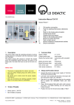
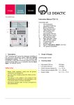
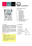
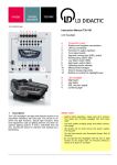
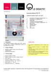
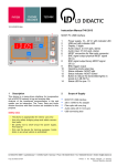
11/14-W2010-Wei Instruction Manual 739 942 A 2 1 3 4 10a 9 11 5 10b 6 15 12 13 7 8 B 14 1 Description The HV battery simulator supplies the universal converter, 735297, with network voltage of 230 V/50 Hz. It simulates an HV battery (hybrid vehicle) to supply the inverter with high direct voltage. Use this device only in connection with the following components: 735297, Universal converter 3 x 230 V 735292, Control unit block commutation 739943, Set of masks Hybrid drive 739946, HV Disconnect* Safety notes - Before initial operation, make sure all connections are correct! - Before initial operation, make sure the device presents no damage! - Use only safety bridging plugs and safety connection leads! - Outputs L and N have a hazardous contact low voltage of 230 VAC! * from serial number 1091964 onwards HV Battery Simulation (739942) A Control unit 1 Power switch 2 Network voltage output L 3 DC voltage input HV+ 4 Network voltage output N 5 Input B 6 DC voltage input HV7 Connection to 735297 8 Protective earth output PE 9 Battery charge adjuster 10a/b Battery disconnect relay state LED's 11 Battery isolating plug 12 UHV ok LED (DC voltage ok) 13 MODE GEN LED (generator) 14 Pushbutton for battery disconnect relay 15 Connection to 735292 B Ribbon cable 2 Scope of Supply The device comprises: this control unit, and a ribbon cable It can be a component of article 739945, Experiment set hybrid drives. 3 Technical Data Supply voltage: 230 VAC, 50 Hz Instruction Manual 4 4.1 Setup and Function Check Setup and Connection Lay mask 739943-01, Control unit block commutation attachment, on device 735292, Control unit block commutation. Lay mask 739943-02, Universal converter attachment, on device 735297, Universal converter 3 x 230 V. Position the devices from left to right in the following order: 1. 739943-01, Control unit block commutation attachment 2. 739942, HV battery simulation 3. 739943-02, Universal converter attachment Supply the device with 230 V/50 Hz alternating voltage by plugging it into a power socket. Use 4 mm safety bridging plugs to link sockets L (2), N (4) and PE (green/yellow socket 8) with the corresponding sockets on the universal converter, 735297. Link sockets HV+ (3), HV- (6) and B (5) with the corresponding sockets on the universal converter, 735297, using 4 mm safety experiment cables. Make sure the red service plug (11) is inserted. Use two ribbon cables (B) to link the PWM characteristic control unit, 725292, with the left D-Sub socket (15) and the universal converter, 735297, with the right D-Sub socket (7). One ribbon cable is part of this device's supply; the other one is part of the supply of 735297. 4.2 Startup Switch on the device with the power switch (1). A self test follows, during which all LED's come on for about 1 second. Turn the dial to set the direct voltage U HV on the universal converter, 735297, going counterclockwise from the rightmost limit until the "UHV ok" LED (12) just comes on. 4.3 Page 2/2 Note: Pulling the service plug is completely safe because there is no high voltage. Use without insulating gloves also presents no risk of injury! Turning the knob to set the direct voltage U HV on the universal converter, 735297, leads to an immediate shutdown of the supply voltage at excessive values, to protect the connected motor. An excess temperature trigger from the electric machine (M/G in) on the universal converter, 735297, also leads to an immediate shutdown of the supply voltage. To be able to switch the device back on, you must briefly switch the power (1) off and back on! 4.4 Settings 4.4.1 Motor/Generator Operation The "MODE GEN" LED (13) indicates the coding connector for the "Generator" operating mode on the PWM characteristic control unit, 735292, (GEN/MOT) is plugged, which leads to the IGBT's in the inverter's switching module not receiving any more control signals. So only the diodes reverse connected to the IGBT function as rectifier diodes. 4.4.2 Battery Charge You can turn the "QBAT" knob (9) to set (simulate) the battery state of charge (SoC). The left stop corresponds to "full battery," and the right stop to "partially discharged battery." The charging capacity is then approx. 30 W. 4.4.3 "Rapid Discharge" Operating Mode After the relay shuts down, the direct voltage is measurable on capacitor "C" of the universal converter, 735297. It slowly declines, since the capacitor is discharging. If you would like a quicker discharge, e.g. to be able to metrologically record the discharge curve in less time, when switching the power on, press and hold the "PEB ON-OFF" button (14) until the contact LED's (12 and 13) briefly flash. Operation 4.3.1 Switch-On Now switch the direct voltage on by pressing the "PEB ON-OFF" (14) button. To limit charging currents the capacitors in the inverter causes, the series resistor first switches the positive terminal on; the negative pole is connected directly. As soon as the intermediate circuit direct voltage has formed in the inverter, the series resistor first has a short-circuit then an interruption. LED's by the relay contacts (10a/b) indicate their switching state: off = contact open, on = contact closed. 4.3.2 Switch-Off You can switch the direct voltage supply back off by pressing the "PEB ON-OFF" (14) button again. Pulling the red service plug (11) leads to an immediate shutdown of the supply voltage. LD DIDACTIC GMBH Leyboldstrasse 1 D-50354 Huerth / Germany Phone +49 (0)2233 604-0 Fax +49 (0)2233 604-222 e-mail: [email protected] by LD Didactic GmbH Printed in the Federal Republic of Germany Technical alterations reserved