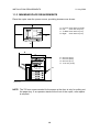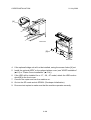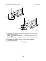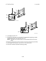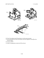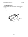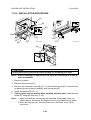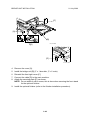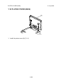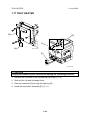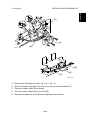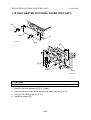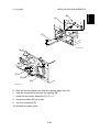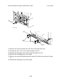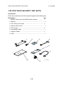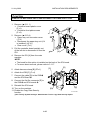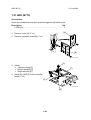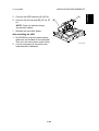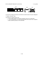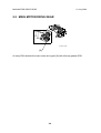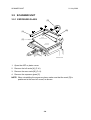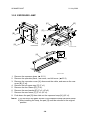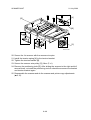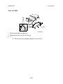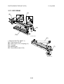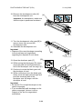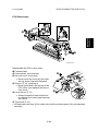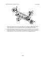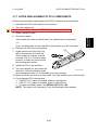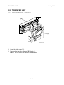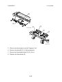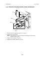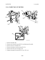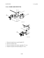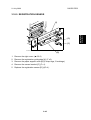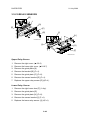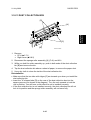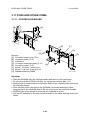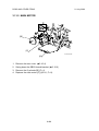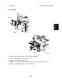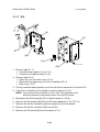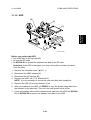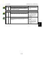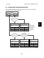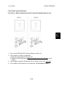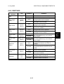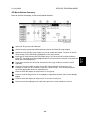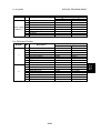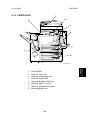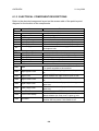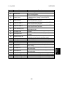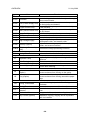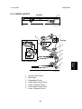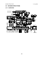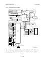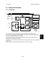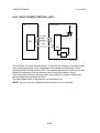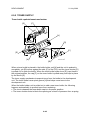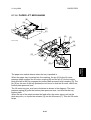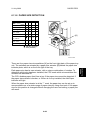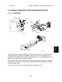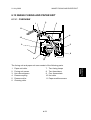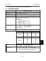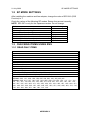
1
Model R-C4/R-C4.5 (Machine Code: B205/B209/D007/D008) SERVICE MANUAL 21 July 2006 Subject to change Conventions Used in this Manual This manual uses several symbols. Symbol = What it means Refer to section number See Core Tech Manual for details Screw Connector E-ring Clip ring Clamp Lengthwise, SEF (Short Edge Feed) Sideways, LEF (Long Edge Feed) Cautions, Notes, etc. The following headings provide special information: WARNING FAILURE TO OBEY WARNING INFORMATION COULD RESULT IN SERIOUS INJURY OR DEATH. CAUTION Obey these guidelines to ensure safe operation and prevent minor injuries. Important • Obey these guidelines to avoid problems such as misfeeds, damage to originals, loss of valuable data and to prevent damage to the machine. IMPORTANT • ALWAYS OBEY THESE GUIDELINES TO AVOID SERIOUS PROBLEMS SUCH AS MISFEEDS, DAMAGE TO ORIGINALS, LOSS OF VALUABLE DATA AND TO PREVENT DAMAGE TO THE MACHINE. BOLD IS ADDED FOR EMPHASIS. NOTE: This information provides tips and advice about how to best service the machine. IMPORTANT SAFETY NOTICES REVENTION OF PHYSICAL INJURY 1. Before disassembling or assembling parts of the copier and peripherals, make sure that the copier power cord is unplugged. 2. The wall outlet should be near the copier and easily accessible. 3. If any adjustment or operation check has to be made with exterior covers off or open while the main switch is turned on, keep hands away from electrified or mechanically driven components. 4. If a job has started before the copier completes the warm-up or initializing period, keep hands away from the mechanical and electrical components because the starts making copies as soon as the warm-up period is completed. 5. The inside and the metal parts of the fusing unit become extremely hot while the copier is operating. Be careful to avoid touching those components with your bare hands. 6. Keep the machine away from flammable liquids, gases, and aerosols. A fire or an explosion might occur. HEALTH SAFETY CONDITIONS Toner is non-toxic, but if you get it in your eyes by accident, it may cause temporary eye discomfort. Try to remove with eye drops or flush with water as first aid. If unsuccessful, get medical attention. SAFETY AND ECOLOGICAL NOTES FOR DISPOSAL 1. Do not incinerate the toner cassettes. Toner dust may ignite suddenly when exposed to an open flame. 2. Dispose of toner cassettes in accordance with local regulations. (This is a non-toxic unit.) 3. Dispose of replaced parts in accordance with local regulations. OBSERVANCE OF ELECTRICAL SAFETY STANDARDS 1. The copier and its peripherals must be installed and maintained by a customer service representative who has completed the training course on those models. 2. The NVRAM on the Controller board has a lithium battery which can explode if replaced incorrectly. Replace the NVRAM only with an identical one. Do not recharge or burn this battery. Used NVRAM must be handled in accordance with local regulations. 3. The danger of explosion exists if batteries on the FCU, MBU and JBIG are incorrectly replaced. Replace only with the same or an equivalent type recommended by the manufacturer. Discard used batteries in accordance with the manufacturer’s instructions. LASER SAFETY The Center for Devices and Radiological Health (CDRH) prohibits the repair of laser-based optical units in the field. The optical housing unit can only be repaired in a factory or at a location with the requisite equipment. The laser subsystem is replaceable in the field by a qualified Customer Engineer. The laser chassis is not repairable in the field. Customer engineers are therefore directed to return all chassis and laser subsystems to the factory or service depot when replacement of the optical subsystem is required. WARNING Use of controls, or adjustment, or performance of procedures other than those specified in this manual may result in hazardous radiation exposure. WARNING FOR LASER UNIT WARNING: Turn off the main switch before attempting any of the procedures in the Laser Unit section. Laser beams can seriously damage your eyes. CAUTION MARKING: LASER-4.WMF Safety Precautions for This Machine Before moving the mainframe: • Disconnect all peripheral units (finisher, LCT, etc.) from the mainframe. • Pull the slide handles out of the mainframe and use them to lift the mainframe. TABLE OF CONTENTS 1. INSTALLATION PROCEDURE.................................................... 1-1 1.1 INSTALLATION REQUIREMENTS ...........................................................1-1 1.1.1 ENVIRONMENT ...............................................................................1-1 1.1.2 MACHINE LEVEL .............................................................................1-1 1.1.3 MINIMUM SPACE REQUIREMENTS...............................................1-2 1.1.4 POWER REQUIREMENTS ..............................................................1-3 1.2 COPIER INSTALLATION ..........................................................................1-4 1.2.1 POWER SOCKETS FOR PERIPHERALS .......................................1-4 1.2.2 INSTALLATION FLOW CHART .......................................................1-5 1.2.3 ACCESSORY CHECK......................................................................1-6 1.2.4 INSTALLATION PROCEDURE ........................................................1-7 Tapes and Retainers.............................................................................1-7 Developer .............................................................................................1-8 Toner Bottle ........................................................................................1-12 Emblem, Decals..................................................................................1-13 1.3 PAPER TRAY UNIT INSTALLATION ......................................................1-15 1.3.1 ACCESSORY CHECK....................................................................1-15 1.3.2 INSTALLATION PROCEDURE ......................................................1-16 1.4 LCT INSTALLATION ...............................................................................1-19 1.4.1 ACCESSORY CHECK....................................................................1-19 1.4.2 INSTALLATION PROCEDURE ......................................................1-20 1.5 ARDF INSTALLATION ............................................................................1-23 1.5.1 ACCESSORY CHECK....................................................................1-23 1.5.2 INSTALLATION PROCEDURE ......................................................1-24 1.6 INTERCHANGE UNIT INSTALLATION...................................................1-28 1.6.1 COMPONENT CHECK...................................................................1-28 1.6.2 INSTALLATION PROCEDURE ......................................................1-29 1.7 1-BIN TRAY UNIT INSTALLATION .........................................................1-31 1.7.1 COMPONENT CHECK...................................................................1-31 1.7.2 INSTALLATION PROCEDURE ......................................................1-32 1.8 SHIFT TRAY............................................................................................1-35 1.8.1 COMPONENT CHECK...................................................................1-35 1.8.2 INSTALLATION PROCEDURE ......................................................1-36 1.9 BY-PASS FEED UNIT INSTALLATION...................................................1-38 1.9.1 COMPONENTS CHECK ................................................................1-38 1.9.2 INSTALLATION PROCEDURE ......................................................1-39 1.10 DUPLEX UNIT INSTALLATION ............................................................1-41 1.10.1 ACCESSORY CHECK..................................................................1-41 1.10.2 INSTALLATION PROCEDURE ....................................................1-42 1.11 BRIDGE UNIT INSTALLATION .............................................................1-44 1.11.1 ACCESSORY CHECK..................................................................1-44 1.11.2 INSTALLATION PROCEDURE ....................................................1-45 i 1.12 1000-SHEET FINISHER INSTALLATION .............................................1-47 1.12.1 ACCESSORY CHECK..................................................................1-47 1.12.2 INSTALLATION PROCEDURE ....................................................1-48 1.13 500-SHEET FINISHER (B442) INSTALLATION....................................1-51 1.13.1 ACCESSORY CHECK..................................................................1-51 1.13.2 INSTALLATION PROCEDURE ....................................................1-52 1.14 PLATEN COVER (B406) .......................................................................1-54 1.15 KEY COUNTER.....................................................................................1-55 1.16 OPTICS ANTI-CONDENSATION HEATER...........................................1-57 1.17 TRAY HEATER .....................................................................................1-58 1.18 TRAY HEATER (OPTIONAL PAPER TRAY UNIT) ...............................1-60 1.19 TRAY HEATER (OPTIONAL LCT) ........................................................1-63 1.20 COPY DATA SECURITY UNIT (B770)..................................................1-66 1.21 HDD (B773) ...........................................................................................1-68 1.22 DATA OVERWRITE SECURITY UNIT (B735) ......................................1-70 Before You Begin… ............................................................................1-70 Seal Check and Removal ...................................................................1-71 Installation...........................................................................................1-72 2. PREVENTIVE MAINTENANCE SCHEDULE ............................... 2-1 2.1 PM TABLE.................................................................................................2-1 2.2 MAIN MOTOR DRIVE GEAR ....................................................................2-4 3. REPLACEMENT AND ADJUSTMENT ........................................ 3-1 3.1 SPECIAL TOOLS AND LUBRICANTS ................................................3-1 3.2 SPECIAL TOOLS ................................................................................3-1 3.3 LUBRICANTS............................................................................................3-1 3.4 GENERAL CAUTIONS..............................................................................3-2 3.4.1 PCU (PHOTOCONDUCTOR UNIT) .................................................3-2 3.4.2 TRANSFER ROLLER UNIT..............................................................3-2 3.4.3 SCANNER UNIT...............................................................................3-2 3.4.4 LASER UNIT ....................................................................................3-3 3.4.5 FUSING UNIT...................................................................................3-3 3.4.6 PAPER FEED ...................................................................................3-3 3.4.7 OTHERS...........................................................................................3-3 3.5 SCANNER UNIT........................................................................................3-4 3.5.1 EXPOSURE GLASS.........................................................................3-4 3.5.2 SCANNER EXTERIOR/OPERATION PANEL ..................................3-5 3.5.3 LENS BLOCK ASSEMBLY...............................................................3-6 3.5.4 ORIGINAL SIZE SENSORS .............................................................3-7 3.5.5 EXPOSURE LAMP ...........................................................................3-8 3.5.6 SCANNER MOTOR/LAMP STABILIZER..........................................3-9 3.5.7 SCANNER WIRES .........................................................................3-10 3.6 LASER UNIT ...........................................................................................3-13 3.6.1 CAUTION DECAL LOCATIONS .....................................................3-13 3.6.2 LASER UNIT ..................................................................................3-14 3.6.3 POLYGON MIRROR MOTOR ........................................................3-15 3.6.4 LD UNIT..........................................................................................3-16 3.6.5 LASER SYNCHRONIZATION DETECTOR....................................3-17 ii 3.7 PHOTOCONDUCTOR UNIT (PCU) ........................................................3-18 3.7.1 PCU REMOVAL..............................................................................3-18 3.7.2 PICK-OFF PAWLS .........................................................................3-19 3.7.3 OPC DRUM ....................................................................................3-20 3.7.4 CHARGE ROLLER, CLEANING ROLLER .....................................3-21 3.7.5 CLEANING BLADE.........................................................................3-22 3.7.6 DEVELOPER..................................................................................3-23 3.7.7 AFTER REPLACEMENT OF PCU COMPONENTS .......................3-27 3.8 TRANSFER UNIT....................................................................................3-28 3.8.1 TRANSFER ROLLER UNIT............................................................3-28 3.8.2 IMAGE DENSITY SENSOR ...........................................................3-29 3.9 FUSING/EXIT ..........................................................................................3-30 3.9.1 FUSING UNIT.................................................................................3-30 3.9.2 THERMISTORS..............................................................................3-30 3.9.3 THERMOSTATS.............................................................................3-31 3.9.4 HOT ROLLER AND FUSING LAMP ...............................................3-33 3.9.5 PRESSURE ROLLER/CLEANING ROLLER ..................................3-35 3.9.6 PAPER EXIT SENSOR/PAPER OVERFLOW SENSOR................3-36 3.10 PAPER FEED........................................................................................3-37 3.10.1 FEED ROLLER: TRAY 1 ..............................................................3-37 3.10.2 FEED ROLLER: TRAY 2 ..............................................................3-38 3.10.3 PAPER END SENSOR.................................................................3-39 3.10.4 PAPER TRAY LIFT MOTORS ......................................................3-40 3.10.5 REGISTRATION CLUTCH ...........................................................3-41 3.10.6 PAPER FEED CLUTCHES...........................................................3-42 Lower Paper Feed Clutch ...................................................................3-42 Upper Paper Feed Clutch. ..................................................................3-42 3.10.7 RELAY CLUTCHES......................................................................3-43 3.10.8 PAPER SIZE DETECTOR............................................................3-44 3.10.9 REGISTRATION SENSOR...........................................................3-45 3.10.10 RELAY SENSORS .....................................................................3-46 Upper Relay Sensor............................................................................3-46 Lower Relay Sensor............................................................................3-46 3.10.11 DUST COLLECTION BOX .........................................................3-47 3.11 PCBS AND OTHER ITEMS...................................................................3-48 3.11.1 CONTROLLER BOARD ...............................................................3-48 3.11.2 NVRAM.........................................................................................3-49 3.11.3 SBCU BOARD ..............................................................................3-50 3.11.4 POWER PACK .............................................................................3-51 3.11.5 MAIN MOTOR ..............................................................................3-52 3.11.6 PSU ..............................................................................................3-53 3.11.7 IPU................................................................................................3-54 3.11.8 HDD..............................................................................................3-55 Important Notes About HDD Replacement .........................................3-56 iii 3.12 COPY ADJUSTMENTS: PRINTING/SCANNING ..................................3-57 3.12.1 PRINTING ....................................................................................3-57 Registration - Leading Edge/Side-to-Side...........................................3-57 Blank Margin.......................................................................................3-58 Main Scan Magnification.....................................................................3-58 Parallelogram Image Adjustment ........................................................3-59 3.12.2 SCANNING...................................................................................3-60 Registration: Platen Mode...................................................................3-60 Magnification.......................................................................................3-60 Standard White Density Adjustment ...................................................3-61 3.12.3 ADF IMAGE ADJUSTMENT .........................................................3-62 Registration.........................................................................................3-62 Sub Scan Magnification ......................................................................3-62 3.12.4 TOUCH SCREEN CALIBRATION ................................................3-63 4. TROUBLESHOOTING ................................................................. 4-1 4.1 SERVICE CALL CONDITIONS .................................................................4-1 4.1.1 SUMMARY .......................................................................................4-1 4.1.2 SC CODE DESCRIPTIONS .............................................................4-2 4.2 SELF-DIAGNOSTIC MODE ....................................................................4-18 4.2.1 SELF-DIAGNOSTIC MODE AT POWER ON .................................4-18 4.2.2 DETAILED SELF-DIAGNOSTIC MODE .........................................4-19 Executing Detailed Self-Diagnosis ......................................................4-19 4.3 PAPER FEED TROUBLESHOOTING.....................................................4-21 4.4 SKEWED IMAGE ....................................................................................4-22 4.5 IMAGE PROBLEMS ................................................................................4-23 4.5.1 SKEWED, TRAPEZOID AND PARALLELOGRAM IMAGES..........4-23 Skewed Images ..................................................................................4-23 Trapezoid Images ...............................................................................4-23 Parallelogram Images .........................................................................4-24 4.5.2 CHECKING IMAGES WITH THE TRIMMING PATTERN...............4-25 4.5.3 CORRECTING THE IMAGES ........................................................4-26 Correcting Skewed Images.................................................................4-26 Correcting Trapezoid Images..............................................................4-29 Correcting Parallelogram Images .......................................................4-30 4.6 ELECTRICAL COMPONENT DEFECTS ................................................4-31 4.6.1 SENSORS ......................................................................................4-31 4.6.2 SWITCHES.....................................................................................4-33 4.7 BLOWN FUSE CONDITIONS .................................................................4-34 iv 5. SERVICE TABLES....................................................................... 5-1 5.1 SERVICE PROGRAM MODE....................................................................5-1 5.1.1 SERVICE MODE LOCK/UNLOCK....................................................5-1 5.1.2 SERVICE PROGRAM MODE OPERATION.....................................5-2 Entering and Exiting SP mode ..............................................................5-2 SP Mode Button Summary ...................................................................5-3 Switching Between SP Mode and Copy Mode for Test Printing ...........5-4 Selecting the Program Number.............................................................5-4 5.1.3 SERVICE PROGRAM MODE TABLES ............................................5-5 SP1XXX: Feed......................................................................................5-6 SP2XXX: Drum ...................................................................................5-15 SP4-XXX: Scanner .............................................................................5-27 SP5XXX: Mode ...................................................................................5-38 SP6XXX: Peripherals..........................................................................5-74 SP7XXX: Data Log .............................................................................5-76 SP8-xxx: Data Log2 ............................................................................5-81 5.1.4 TEST PATTERN PRINTING (SP2902-3) .....................................5-115 5.1.5 INPUT CHECK .............................................................................5-116 Main Machine Input Check (SP5803) ...............................................5-116 ARDF Input Check (SP6007)............................................................5-119 Finisher Input Check (SP6117).........................................................5-120 5.1.6 OUTPUT CHECK .........................................................................5-122 Main Machine Output Check (SP5804).............................................5-122 ARDF Output Check (SP6008) .........................................................5-124 Finisher Output Check (SP6118) ......................................................5-124 5.1.7 SMC DATA LISTS (SP5990) ........................................................5-125 5.1.8 MEMORY ALL CLEAR (SP5801) .................................................5-126 5.1.9 APS OUTPUT DISPLAY (SP4301)...............................................5-127 5.1.10 DF APS SENSOR OUTPUT DISPLAY (SP6901).......................5-128 5.1.11 NIP BAND WIDTH MEASUREMENT (SP1109) .........................5-129 5.2 FIRMWARE UPDATE ...........................................................................5-130 5.3 SOFTWARE RESET .............................................................................5-131 5.4 SYSTEM SETTINGS AND COPY SETTING RESET............................5-131 5.4.1 SYSTEM SETTING RESET .........................................................5-131 5.4.2 COPIER SETTING RESET ..........................................................5-132 5.5 USER TOOLS .......................................................................................5-133 5.5.1 HOW TO USE UP MODE.............................................................5-133 UP Mode Initial Screen: User Tools/Counter Display........................5-133 System Settings ................................................................................5-133 Copier/Document Server Features ...................................................5-133 Printer, Facsimile, Scanner Settings .................................................5-134 Inquiry ...............................................................................................5-134 Counter .............................................................................................5-135 5.6 LEDS .....................................................................................................5-136 Controller ..........................................................................................5-136 SBCU................................................................................................5-136 v 5.7 DIP SWITCHES.....................................................................................5-136 Controller ..........................................................................................5-136 SBCU................................................................................................5-136 5.8 USING THE DEBUG LOG.....................................................................5-137 5.8.1 SWITCHING ON AND SETTING UP SAVE DEBUG LOG ...........5-137 5.8.2 RETRIEVING THE DEBUG LOG FROM THE HDD ....................5-141 5.8.3 RECORDING ERRORS MANUALLY ...........................................5-141 5.8.4 NEW DEBUG LOG CODES .........................................................5-142 SP5857-015 Copy SD Card-to-SD Card: Any Desired Key ..............5-142 SP5857-016 Create a File on HDD to Store a Log ...........................5-142 SP5857-017 Create a File on SD Card to Store a Log .....................5-142 6. DETAILS....................................................................................... 6-1 6.1 OVERVIEW ...............................................................................................6-1 6.1.1 MECHANICAL COMPONENTS........................................................6-1 6.1.2 PAPER PATH ...................................................................................6-3 6.1.3 ELECTRICAL COMPONENT DESCRIPTIONS ...............................6-4 6.1.4 DRIVE LAYOUT ...............................................................................6-7 6.2 BOARD STRUCTURE...............................................................................6-8 6.2.1 OVERVIEW ......................................................................................6-8 6.2.2 CONTROLLER BOARD .................................................................6-10 6.3 COPY PROCESS....................................................................................6-13 6.4 SCANNING..............................................................................................6-15 6.4.1 OVERVIEW ....................................................................................6-15 6.4.2 SCANNER DRIVE ..........................................................................6-16 6.4.3 ORIGINAL SIZE DETECTION: PLATEN MODE ............................6-17 6.5 IMAGE PROCESSING ............................................................................6-19 6.5.1 OVERVIEW ....................................................................................6-19 6.5.2 SBU (SENSOR BOARD UNIT).......................................................6-20 6.5.3 AUTO IMAGE DENSITY.................................................................6-21 6.5.4 ORIGINAL TYPE SETTINGS .........................................................6-22 6.5.5 IPU (IMAGE PROCESSING UNIT).................................................6-23 Overview.............................................................................................6-23 Image Processing Path.......................................................................6-24 SP Modes for Each Image Processing Step .......................................6-25 Auto Shading ......................................................................................6-30 Pre-Filtering ........................................................................................6-30 Main Scan Magnification/Reduction....................................................6-30 Mirroring for ADF Mode ......................................................................6-30 Characteristic Detection......................................................................6-31 Filtering ...............................................................................................6-31 Background Erase ..............................................................................6-32 ID Gamma (g) Correction....................................................................6-32 Gradation Processing .........................................................................6-32 Line width correction ...........................................................................6-33 6.5.6 VIDEO CONTROL UNIT (GAVD) ...................................................6-34 Fine Character and Image (FCI) .........................................................6-34 vi 6.6 LASER EXPOSURE................................................................................6-35 6.6.1 OVERVIEW ....................................................................................6-35 6.6.2 AUTO POWER CONTROL (APC) ..................................................6-36 6.6.3 LD SAFETY SWITCH .....................................................................6-37 6.7 PHOTOCONDUCTOR UNIT (PCU) ........................................................6-38 6.7.1 OVERVIEW ....................................................................................6-38 6.7.2 DRIVE.............................................................................................6-39 6.8 DRUM CHARGE .....................................................................................6-40 6.8.1 OVERVIEW ....................................................................................6-40 6.8.1 CHARGE ROLLER VOLTAGE CORRECTION ..............................6-41 Correction for Environmental Conditions ............................................6-41 6.8.2 ID SENSOR PATTERN PRODUCTION TIMING............................6-42 6.8.3 DRUM CHARGE ROLLER CLEANING ..........................................6-43 6.9 DEVELOPMENT .....................................................................................6-44 6.9.1 OVERVIEW ....................................................................................6-44 6.9.2 DRIVE.............................................................................................6-45 6.9.3 DEVELOPER MIXING ....................................................................6-46 6.9.4 DEVELOPMENT BIAS ...................................................................6-47 6.9.5 TONER SUPPLY ............................................................................6-48 Toner bottle replenishment mechanism ..............................................6-48 Toner supply mechanism....................................................................6-49 6.9.6 TONER DENSITY CONTROL ........................................................6-50 Overview.............................................................................................6-50 Toner density sensor initial setting......................................................6-52 Toner density measurement ...............................................................6-52 Vsp/Vsg detection ...............................................................................6-52 Toner supply reference voltage (Vref) determination ..........................6-52 Toner supply determination ................................................................6-52 Toner Supply Motor On Time Determinations.....................................6-53 6.9.7 TONER SUPPLY IN ABNORMAL SENSOR CONDITIONS...........6-54 ID sensor ............................................................................................6-54 TD Sensor...........................................................................................6-54 6.9.8 TONER NEAR END/END DETECTION AND RECOVERY............6-54 Toner Near End Detection ..................................................................6-54 Toner Near End Recovery ..................................................................6-55 Toner End Detection ...........................................................................6-55 Toner End Recovery ...........................................................................6-55 6.10 DRUM CLEANING AND TONER RECYCLING.....................................6-56 6.10.1 DRUM CLEANING........................................................................6-56 6.10.2 TONER RECYCLING ...................................................................6-57 vii 6.11 PAPER FEED........................................................................................6-58 6.11.1 OVERVIEW ..................................................................................6-58 6.11.2 PAPER FEED DRIVE MECHANISM ............................................6-59 6.11.3 PAPER FEED AND SEPARATION MECHANISM........................6-60 6.11.4 PAPER LIFT MECHANISM ..........................................................6-61 6.11.5 PAPER END DETECTION ...........................................................6-63 6.11.6 PAPER HEIGHT DETECTION .....................................................6-64 6.11.7 FEED PRESSURE ADJUSTMENT FOR PAPER SIZE................6-66 Overview.............................................................................................6-66 Paper Size Thresholds........................................................................6-66 Feed Pressure Adjustment .................................................................6-67 Effect of the Amount of Remaining Paper...........................................6-67 6.11.8 PAPER SIZE DETECTION...........................................................6-69 6.11.9 SPECIAL PAPER SETTING.........................................................6-70 6.11.10 SIDE AND END FENCES...........................................................6-71 Side Fences........................................................................................6-71 End Fence ..........................................................................................6-71 6.11.11 PAPER REGISTRATION............................................................6-72 6.12 IMAGE TRANSFER AND PAPER SEPARATION .................................6-73 6.12.1 OVERVIEW ..................................................................................6-73 6.12.2 IMAGE TRANSFER CURRENT TIMING......................................6-74 6.12.3 TRANSFER ROLLER CLEANING................................................6-75 6.12.4 PAPER SEPARATION MECHANISM...........................................6-76 6.13 IMAGE FUSING AND PAPER EXIT......................................................6-77 6.13.1 OVERVIEW ..................................................................................6-77 6.13.2 FUSING DRIVE AND RELEASE MECHANISM ...........................6-78 6.13.3 FUSING ENTRANCE GUIDE SHIFT MECHANISM .....................6-79 6.13.4 PRESSURE ROLLER...................................................................6-80 6.13.5 CLEANING MECHANISM ............................................................6-81 6.13.6 FUSING TEMPERATURE CONTROL..........................................6-82 Temperature Control...........................................................................6-82 Fusing Lamp Control...........................................................................6-83 6.13.7 OVERHEAT PROTECTION .........................................................6-84 6.13.8 PAPER EXIT ................................................................................6-85 6.14 ENERGY SAVER MODES ....................................................................6-86 6.14.1 OVERVIEW ..................................................................................6-86 6.14.2 ENERGY SAVER MODE..............................................................6-87 Entering the energy saver mode.........................................................6-87 What happens in energy saver mode .................................................6-87 Return to stand-by mode ....................................................................6-87 6.14.3 AUTO OFF MODE........................................................................6-88 Entering off stand-by and off modes ...................................................6-88 Off Stand-by mode..............................................................................6-88 Off Mode .............................................................................................6-88 Returning to stand-by mode................................................................6-88 viii 7. OVERALL MACHINE INFORMATION......................................... 7-1 7.1 SPECIFICATIONS.....................................................................................7-1 7.2 MACHINE CONFIGURATION ...................................................................7-4 7.2.1 SYSTEM COMPONENTS ................................................................7-4 7.2.2 OPTIONS TABLE .............................................................................7-6 Copier options.......................................................................................7-6 Fax option .............................................................................................7-6 Printer/scanner options .........................................................................7-6 ix INSTALLATION REQUIREMENTS 1. INSTALLATION PROCEDURE 1.1 INSTALLATION REQUIREMENTS 1.1.1 ENVIRONMENT 1. Temperature Range: 10°C to 32°C (50°F to 89.6°F) 2. Humidity Range: 15% to 80% RH 3. Ambient Illumination: Less than 1,500 lux (do not expose to direct sunlight.) 4. Ventilation: Room air should turn over at least 30 m3/hr/person 5. Ambient Dust: Less than 0.10 mg/m3 6. Avoid an area which is exposed to sudden temperature changes. This includes: 1) Areas directly exposed to cool air from an air conditioner. 2) Areas directly exposed to heat from a heater. 7. Do not place the machine in an area where it will be exposed to corrosive gases. 8. Do not install the machine at any location over 2,000 m (6,500 ft.) above sea level. 9. Place the copier on a strong and level base. (Inclination on any side should be no more than 5 mm.) 10. Do not place the machine where it may be subjected to strong vibrations. 1.1.2 MACHINE LEVEL Front to back: Within 5 mm (0.2") of level Right to left: With in 5 mm (0.2") of level 1-1 Installation 21 July 2006 INSTALLATION REQUIREMENTS 21 July 2006 1.1.3 MINIMUM SPACE REQUIREMENTS Place the copier near the power source, providing clearance as shown: C B A: B: C: D: In Front: Over 750 mm (29.6") Left: Over 100 mm (0.4") To Rear: Over 100 mm (0.4") Right: Over 100 mm (0.4") E: F: G: H: 620 mm (24.4") 640 mm (25.2") 550 mm (21.7") 1137 mm (44.8") D A B089I201.WMF E F G H B089I202.WMF NOTE: The 750 mm recommended for the space at the front is only for pulling out the paper tray. If an operator stands at the front of the copier, more space is required. 1-2 INSTALLATION REQUIREMENTS 1.1.4 POWER REQUIREMENTS CAUTION 1. Make sure that the wall outlet is near the copier and easily accessible. Make sure the plug is firmly inserted in the outlet. 2. Avoid multi-wiring. 3. Be sure to ground the machine. 1. Input voltage level: 120 V, 60 Hz: More than 12 A 220 V ~ 240 V, 50 Hz/60 Hz: More than 7 A 110V, 50 Hz/60 Hz: More than 13 A 2. Permissible voltage fluctuation: ±10 % 3. Do not set anything on the power cord. 1-3 Installation 21 July 2006 COPIER INSTALLATION 21 July 2006 1.2 COPIER INSTALLATION 1.2.1 POWER SOCKETS FOR PERIPHERALS CAUTION Rating voltage for peripherals. Make sure to plug the cables into the correct sockets. 1. ADF 1. Rating voltage output connector for accessory Max. DC24 V 2. Bridge Unit or Shift Tray 1. Rating voltage output connector for accessory Max. DC24 V B205I107.WMF 4. By-pass Tray 1. Rating voltage output connector for accessory Max. DC24 V 3. Duplex Unit 1. Rating voltage output connector for accessory Max. DC24 V 1-4 INSTALLATION REQUIREMENTS 1.2.2 INSTALLATION FLOW CHART The following flow chart shows how to install the optional units more efficiently. Unpack the copier Does the user require the Paper Tray Unit, LCT, or Finisher? Yes No Place the copier on the Paper Tray Unit or LCT Install the Paper Tray Unit or LCT Install the copier Does the user require the Memory Unit? Yes No Install the Memory Unit Does the user require the By-pass Tray? Yes No Install the By-pass Tray Does the user require the Shift Tray? Yes No Install the Shift Tray Does the user require the Finisher? Yes No Install the Bridge Unit Install the Finisher Does the user require the Duplex Unit and/or 1-bin Tray Unit ? Yes No Install the Interchange Unit Install the Duplex Unit and/or 1-bin Tray Unit Install the ARDF or Platen Cover (if required) B089I513.WMF 1-5 Installation 21 July 2006 COPIER INSTALLATION 21 July 2006 1.2.3 ACCESSORY CHECK Check the quantity and condition of the accessories in the box against the following list: Description Q'ty 1. Paper Tray Decal.................................................................1 2. Emblem Cover .....................................................................1 3. Emblem ...............................................................................1 4. Model Name Decal ..............................................................1 5. End Fence ...........................................................................1 6. HDD Caution Decal (-17, -29, -57 only) ...............................1 7. Operating Instructions – System Setting..............................1 8. Operating Instructions – Copy Reference............................1 1-6 21 July 2006 INSTALLATION REQUIREMENTS Installation 1.2.4 INSTALLATION PROCEDURE Tapes and Retainers B205I104.WMF B205I904.WMF [A] [B] B205I905.WMF CAUTION Unplug the machine power cord before starting the following procedure. If the optional paper tray or the optional LCT is going to be installed now, put the copier on the paper tray unit or the LCT first, then install these options, then install the copier. NOTE: Keep the shipping retainers after installing the machine. They will be reused if the machine is moved to another location in the future. 1. Remove the tapes and the shipping retainer [A] on the exterior of the copier. 2. Install the end fence [B]. 1-7 COPIER INSTALLATION 21 July 2006 Developer [B] [A] [C] [D] B205I920.WMF 1. Spread the vinyl sheet provided with the developer kit on a flat surface. 2. Open the right door [A] 3. Open the front door [B]. 4. Push the latch [C] and remove the PCU [D]. 1-8 INSTALLATION REQUIREMENTS Installation 21 July 2006 [B] [A] [C] [D] B205I102A.WMF 5. Remove the front screw [A] ( x1) 6. Remove the rear screws [B] ( x2) 7. Release the rear tab [C] then front tab [D], then separate the top and bottom. Important: Be sure to release the rear tab first and the front tab second. 1-9 COPIER INSTALLATION 21 July 2006 [B] [A] [C] B205I103.WMF 8. Open the developer pack [A]. 9. While turning the black gear [B], slowly move the pack left and right and pour half of the developer over the auger [C]. 10. Continue to turn the black gear until the developer is level. 11. While continuing to turn the black gear, slowly move the pack left and right and pour the remaining half of the developer over the auger until the developer is level. Important • Be careful. Do not spill developer on the gears and sponges. • If you accidentally spill developer on the gears or sponges, remove it with a magnet or the tip of a magnetized screwdriver. 1-10 INSTALLATION REQUIREMENTS Installation 21 July 2006 Re-assembly B205I920B.WMF 1. Make sure that all of the holes and tabs on are engaged at , , , and . Then push down to lock the tabs on the front and rear end of the PCU. 2. Make sure that the holes for the screws on the front and rear end of the PCU are aligned correctly. If the holes are not aligned correctly, make sure that the tabs at the front, rear, and left side of the PCU are engaged correctly. Important • Reattach the rear screws ( x2) first, then reattach the front screw ( x1). • Do not push down on the top of the PCU when you attach the rear and front screws 1-11 COPIER INSTALLATION Toner Bottle 21 July 2006 [D] [F] [E] [C] [A] [B] B205I907.WMF [G] B089I500.WMF 1. Raise the toner bottle holder lever [A], push lever [B] down, and pull the toner bottle holder [C] out. 2. Shake the toner bottle [D]. NOTE: Do not remove the toner bottle cap [E] until after shaking. 3. Unscrew the bottle cap [E] and insert the bottle into the holder. NOTE: Do not touch the inner bottle cap [F]. 4. Reposition the holder and press down the holder lever to secure the bottle. 5. Open the right cover. 6. Rotate the green fusing pressure lever [G] to the up position. 1-12 21 July 2006 INSTALLATION REQUIREMENTS Installation Emblem, Decals [C] [B] [A] B205I105.WMF [D] B205I909.WMF 1. Attach the emblem [A] and panel [B] to the front door [C]. NOTE: Push the panel in until the emblem and panel move into their positions. You will hear a click. 2. Pull the paper tray out and turn the paper size dial to select the appropriate size. Adjust the side guides and end guide to match the paper size. NOTE: To move the side guides, first pull out the tray fully, then push down the green lock at the rear of the tray. 3. Attach the appropriate paper tray number decal [D] to each paper tray. NOTE: Paper tray number decals are also used for the optional paper tray or the optional LCT. Keep any remaining decals for use with these optional units. 1-13 COPIER INSTALLATION 21 July 2006 [A] B205I910.WMF [B] B205I108.WMF 4. If the optional bridge unit will not be installed, swing the sensor feeler [A] out. 5. Install the optional ARDF or the optional platen cover (see "ARDF Installation" (1.5) or "Platen Cover Installation" (1.14)). 6. If the HDD will be installed for a –17, -29, –57 model, attach the HDD caution decal [B] to the front cover. 7. Connect the copier and turn the machine on. 8. Go into the SP mode and do SP2801 (Developer Initialization). 9. Do some test copies to make sure that the machine operates correctly. 1-14 INSTALLATION REQUIREMENTS Installation 21 July 2006 1.3 PAPER TRAY UNIT INSTALLATION 1.3.1 ACCESSORY CHECK Check the quantity and condition of the accessories against the following list. Description Q’ty 1. Securing Bracket .................................................................2 2. Screw – M4 x 10 ..................................................................4 1-15 PAPER TRAY UNIT INSTALLATION 21 July 2006 1.3.2 INSTALLATION PROCEDURE [A] B390I603.WMF [C] [B] B390I601.WMF CAUTION Unplug the machine power cord before starting the following procedure. 1. Remove the strips of tape. 2. Set the copier [A] on the paper tray unit [B]. NOTE: When installing the copier, be careful not to pinch the cable [C]. 1-16 INSTALLATION REQUIREMENTS Installation 21 July 2006 [C] [A] [C] [B] B390I604.WMF [D] [E] B390I600.WMF 3. Remove the connector cover [A] ( x 1). 4. Connect the cable [B] to the copier, as shown. 5. Attach a securing bracket [C] to each side of the paper tray unit, as shown ( x 1 each). 6. Re-install the connector cover. 7. Remove the 2nd paper tray [D] and secure the paper tray unit [E] ( x 2). 1-17 PAPER TRAY UNIT INSTALLATION 21 July 2006 [A] B390I602.WMF [B] B390I002.WMF 8. Reinstall the 2nd paper tray and attach the appropriate paper tray number decal [A] to the paper tray. NOTE: The paper tray number decal is in the accessory box for the main copier. 9. Rotate the adjuster [B] until the machine cannot be pushed across the floor. 10. Loads paper into the paper trays and select the proper paper size. 11. Turn on the main switch. 12. Check the machine’s operation and copy quality. 1-18 INSTALLATION REQUIREMENTS 1.4 LCT INSTALLATION 1.4.1 ACCESSORY CHECK Check the quantity and condition of the accessories against the following list. Description Q’ty 1. Securing Bracket .................................................................2 2. Screw – M4 x 10 ..................................................................4 3. Paper Size Decal .................................................................1 1-19 Installation 21 July 2006 LCT INSTALLATION 21 July 2006 1.4.2 INSTALLATION PROCEDURE [A] B391I500.WMF [C] [B] B391I505.WMF CAUTION Unplug the machine power cord before starting the following procedure. 1. Remove the strips of tape. 2. Set the copier [A] on the LCT [B]. NOTE: When installing the copier, be careful not to pinch the cable [C]. 1-20 INSTALLATION REQUIREMENTS Installation 21 July 2006 [C] [A] [C] [B] B391I504.WMF [D] B391I501.WMF 3. Remove the connector cover [A] ( x 1). 4. Connect the cable [B] to the copier, as shown. 5. Attach a securing bracket [C] to each side of the LCT, as shown ( x 1 each). 6. Re-install the connector cover. 7. Remove the 2nd paper tray and secure the LCT [D] ( x 2). 1-21 LCT INSTALLATION 21 July 2006 [B] [A] B391I502.WMF [C] B391I506.WMF 8. Load paper into the LCT. 9. Reinstall the 2nd paper tray and attach the appropriate paper tray number decal [A] and paper size decal [B] to the LCT. NOTE: The paper tray number decal is in the accessory box for the main copier. 10. Rotate the adjuster [C] until the machine cannot be pushed across the floor. 11. Loads paper into the paper tray and turn on the main switch. 12. Check the machine’s operation and copy quality. 1-22 INSTALLATION REQUIREMENTS 1.5 ARDF INSTALLATION 1.5.1 ACCESSORY CHECK Check the quantity and condition of the accessories against the following list. Description Q’ty 1. Scale Guide .........................................................................1 2. DF Exposure Glass..............................................................1 3. Stud Screw ..........................................................................2 4. Knob Screw .........................................................................2 5. Original Size Decal ..............................................................2 6. Screwdriver Tool..................................................................1 7. Cloth Holder.........................................................................1 8. Cloth ....................................................................................1 9. Attention Decal – Top Cover................................................1 10. Attention Decal – Scanner .................................................1 4 3 6 1 5 2 7 B386I500.WMF 8 1-23 Installation 21 July 2006 ARDF INSTALLATION 21 July 2006 1.5.2 INSTALLATION PROCEDURE B386I101.WMF CAUTION Unplug the copier power cord before starting the following procedure. 1. Remove the strips of tape. 1-24 [E] INSTALLATION REQUIREMENTS [F] [C] [D] [G] Installation 21 July 2006 [A] [G] [B] B386I107.WMF [H] [H] [I] B386I104.WMF 2. Remove the left scale [A] ( x 2). 3. Peel off the backing [B] of the double-sided tape attached to the glass holder. 4. Place the DF exposure glass [C] on the glass holder. NOTE: When installing the DF exposure glass, make sure that the white point [D] is on the lower front side of the glass, as shown. 5. Peel off the backing [E] of the double-sided tape attached to the rear side of the scale guide [F], then install it ( x 2 removed in step 2). 6. Install the two stud screws [G]. 7. Mount the DF on the copier, then slide the DF to the front as shown. 8. Secure the DF unit with two screws [H]. 9. Connect the cable [I] to the copier. 1-25 ARDF INSTALLATION 21 July 2006 [B] [A] B386I111.WMF B386I110.WMF [C] B386I501.WMF 10. Peel off the platen sheet [A] and place it on the exposure glass. 11. Line up the rear left corner of the platen sheet flush against corner [B] on the exposure glass. 12. Close the ARDF. 13. Attach the appropriate scale decal [C] as shown. 1-26 21 July 2006 INSTALLATION REQUIREMENTS Installation [A] B386I502.WMF [B] [D] B386I503.WMF [C] B386I504.WMF 14. Attach the decal [A] to the top cover as shown, choosing the language most suitable for the machine installed. 15. Line up arrow on the decal [B] with the center of the ADF exposure glass as shown, and attach it to the cover. As with step 14, choose the language most suitable for the machine installed. 16. Attach the cloth holder [C] to the left side of the scanner as shown. 17. Insert the cloth [D] in the cloth holder. 18. Turn the main power switch on. Then check if the document feeder works properly. 19. Make a full size copy. Then check to make sure the registrations (side-to-side and leading edge) and image skew are correct. If they are not, adjust the registrations and image skew (refer to the service manual). 1-27 INTERCHANGE UNIT INSTALLATION 21 July 2006 1.6 INTERCHANGE UNIT INSTALLATION 1.6.1 COMPONENT CHECK Check the quantity and condition of the components against the following list. Description Q’ty 1. Interchange Unit ..................................................................1 2. Connector Cover..................................................................1 3. Tapping Screw M3 x 8 .........................................................1 2 1 3 B416I101.WMF 1-28 21 July 2006 INSTALLATION REQUIREMENTS Installation 1.6.2 INSTALLATION PROCEDURE [B] [A] [C] [D] [E] [H] B416I503.WMF [F] [G] B416I502.WMF CAUTION Unplug the copier power cord before starting the following procedure. 1. Remove all tapes. 2. Open the right cover [A] of the copier. 3. Open cover [B] 4. Remove the metal clip [C]. NOTE: To remove the clip, push the small tab [D] on the clip into the slot [E], then the clip can be removed. 5. Remove the cover [B]. If the optional 1-bin tray unit (B413) will be installed, do steps 6 and 7. 6. Loosen the screw, push down tab [F] with a screwdriver, and remove the front right cover [G]. 7. Slide out the exit cover [H]. 1-29 INTERCHANGE UNIT INSTALLATION 21 July 2006 [B] [A] B416I103.WMF [D] [C] 8. Open the cover [A] of the interchange unit. 9. Install the interchange unit (2 connectors) [B]. 10. Secure the interchange unit with the knob screws [C]. 11. Attach the connector cover [D] ( x 1). 1-30 B416I104.WMF INSTALLATION REQUIREMENTS 1.7 1-BIN TRAY UNIT INSTALLATION 1.7.1 COMPONENT CHECK Check the quantity and condition of the components against the following list. Description Q’ty 1. 1-Bin Tray Unit.....................................................................1 2. Tray .....................................................................................1 3. Sub-Tray..............................................................................1 4. Tray Guide...........................................................................1 5. Paper Guide ........................................................................1 6. Tapping Screw M3 x 8 .........................................................1 5 6 1 2 3 4 B413I101.WMF 1-31 Installation 21 July 2006 1-BIN TRAY UNIT INSTALLATION 21 July 2006 1.7.2 INSTALLATION PROCEDURE [A] B413I501.WMF CAUTION Unplug the copier power cord before starting the following procedure. NOTE: Before installing this 1-bin tray unit, the optional interchange unit (B416) must be installed. 1. Remove all tapes. 2. If the optional bridge unit has been installed, open the right jam removal cover [A] of the bridge unit. If the optional bridge unit is not installed, skip this step. 1-32 INSTALLATION REQUIREMENTS Installation 21 July 2006 [C] [A] [D] [B] B413I500.WMF [E] B413I103.WMF 3. If the front right cover [A] is installed, remove it. 4. Install the 1-bin tray unit [B] ( x 1). 5. Connect the connector [C]. 6. Reinstall the front right cover. 7. Peel off the backing [D] of the double-sided tape attached to the paper guide [E]. Then attach the paper guide to the underside of the scanner unit as shown. 1-33 1-BIN TRAY UNIT INSTALLATION 21 July 2006 [A] [C] [B] B413I105.WMF 8. Install the tray guide [A]. 9. Install the tray [B]. 10. Install the sub-tray [C]. 11. Turn on the main power switch and check the 1-bin tray unit operation. 1-34 INSTALLATION REQUIREMENTS 1.8 SHIFT TRAY 1.8.1 COMPONENT CHECK Check the quantity and condition of the components against the following list. Description Q’ty 1. Shift Tray Unit ......................................................................1 2. Paper Guide - Large ............................................................1 3. Paper Guide - Small ............................................................2 4. Stepped Screw ....................................................................1 2 3 4 1 B459I101.WMF 1-35 Installation 21 July 2006 SHIFT TRAY 21 July 2006 1.8.2 INSTALLATION PROCEDURE [A] [C] B459I104.WMF [B] [C] CAUTION Unplug the copier power cord before starting the following procedure. 1. Remove all tapes. 2. Remove the plate [A]. 3. Install the large paper guide [B] and two small paper guides [C], as shown. 1-36 INSTALLATION REQUIREMENTS Installation 21 July 2006 [C] [B] [A] [D] B459I103.WMF 4. Install the stepped screw [A]. 5. Install the shift tray unit [B], as shown. NOTE: 1) Set the shift tray on the stepped screw. 2) The shift tray must be installed under the paper guide [C] installed in step 3. 6. Connect the cable [D] to the copier. 7. Turn on the main power switch. 8. Check the shift tray operation. 1-37 BY-PASS FEED UNIT INSTALLATION 21 July 2006 1.9 BY-PASS FEED UNIT INSTALLATION 1.9.1 COMPONENTS CHECK Check the quantity and condition of the components against the following list. Description Q’ty 1. By-pass Tray Unit ................................................................1 2. Unit Holder...........................................................................1 3. Tapping Screw ....................................................................2 4. Allen Key .............................................................................1 2 3 4 B415I101.WMF 1 1-38 21 July 2006 INSTALLATION REQUIREMENTS Installation 1.9.2 INSTALLATION PROCEDURE [B] [A] [B] B415I500.WMF CAUTION Unplug the copier power cord before starting the following procedure. 1. Remove all tapes. 2. Remove the entrance cover [A] ( x 2) and two screws [B]. 1-39 BY-PASS FEED UNIT INSTALLATION 21 July 2006 [B] [A] B415I502.WMF B415I501.WMF [C] [D] [D] [C] B415I105.WMF B415I104.WMF 3. Install the unit holder [A] using the Allen key ( x 4 ). NOTE: 1) Make sure that the four screws are tightened in the proper order, as shown above. Otherwise, when the optional duplex unit (B414) is installed, it will not properly lock in place. 2) After securing the unit, store the Allen key in the inner cover [B] for future use. 4. If the optional duplex unit (B414) will be installed: Remove the indicated parts [C] of the by-pass tray unit [D]. 5. Install the by-pass tray unit ( x 2, x 1). 6. Turn the main power switch on and check the by-pass tray function. 7. Make a copy from the by-pass tray. Then check the registration. 1-40 INSTALLATION REQUIREMENTS 1.10 DUPLEX UNIT INSTALLATION 1.10.1 ACCESSORY CHECK Check the quantity and condition of the accessories against the following list. Description Q’ty 1. Duplex Unit ..........................................................................1 2. Connector Cover..................................................................1 3. Bracket ................................................................................1 4. Clip ......................................................................................1 5. Unit Holder...........................................................................1 6. Unit Holder Cover ................................................................1 7. Allen Key .............................................................................1 8. Tapping Screw - M3 x 8 ......................................................4 6 5 1 2 B414I101.WMF 8 3 7 4 B414I102.WMF 1-41 Installation 21 July 2006 DUPLEX UNIT INSTALLATION 21 July 2006 1.10.2 INSTALLATION PROCEDURE [A] [B] [E] [A] [C] [D] [D] [F] B414I103.WMF B414I501.WMF [G] B414I500.WMF CAUTION Unplug the copier power cord before starting the following procedure. NOTE: Before installing the duplex unit, the optional interchange unit (B416) must be installed. 1. Remove all tapes. 2. Remove three covers [A]. 3. Remove the connector cover [B] ( x 1), the entrance cover [C] (2 screws if the by-pass tray has not been installed), and two screws [D]. 4. Install the bracket [E] ( x 1). 5. If the by-pass tray has already been installed, skip this step: Install the unit holder [F] using the Allen key ( x 4). NOTE: 1) Make sure that the four screws are tightened in the proper order, as shown above. Otherwise, the duplex unit will not properly lock in place. 2) After securing the unit, store the Allen key in the inner cover [G] for future use. 1-42 21 July 2006 INSTALLATION REQUIREMENTS Installation [C] [D] [A] [F] [B] [E] [G] B414I104.WMF 6. Set the duplex unit [A] on the unit holder [B] or on the by-pass tray unit if it has already been installed. 7. Attach the link [C] to the shaft [D] and secure it with the clip. 8. Connect the cable [E] and install the connector cover [F] ( x 1). 9. If the by-pass tray has already been installed, skip this step: Install the unit holder cover [G] ( x 2). 10. Turn on the main power switch and check the duplex unit function. 1-43 BRIDGE UNIT INSTALLATION 21 July 2006 1.11 BRIDGE UNIT INSTALLATION 1.11.1 ACCESSORY CHECK Check the quantity and condition of the accessories against the following list. Description Q’ty 1. Bridge Unit ...........................................................................1 2. Securing Plate .....................................................................1 3. Shoulder Screw ...................................................................1 4. Knob Screw .........................................................................1 2 4 1 3 B417I101.WMF 1-44 21 July 2006 INSTALLATION REQUIREMENTS Installation 1.11.2 INSTALLATION PROCEDURE [A] [C] [B] B417I501.WMF B417I500.WMF CAUTION Unplug the copier power cord before starting the following procedure. 1. Remove all tapes. 2. Loosen the screw [A] and remove the front right cover [B]. 3. If the sensor feeler [C] is out, fold it away into the machine. 1-45 BRIDGE UNIT INSTALLATION 21 July 2006 [C] [A] [B] B417I104.WMF [D] [E] B417I103.WMF 4. Remove the cover [A]. 5. Install the bridge unit [B] ( x 1 shoulder, x 1 knob). 6. Reinstall the front right cover [C]. 7. Connect the cable [D] to the main machine. 8. Attach the securing plate [E], as shown. NOTE: Do not attach it with a screw; this is done when securing the front stand for the optional finisher. 9. Install the optional finisher (refer to the finisher installation procedure). 1-46 INSTALLATION REQUIREMENTS 1.12 1000-SHEET FINISHER INSTALLATION 1.12.1 ACCESSORY CHECK Check the quantity and condition of the accessories against the following list. 2 6 1 7 8 5 4 10 3 No. 1 2 3 4 5 6 7 8 9 10 Description Front Joint Bracket Rear Joint Bracket Rear Joint Bracket Grounding Plate Copy Tray Staple Position Decal Screw - M4 x 14 Knob Screw - M4 x 10 Screw - M3 x 8 Knob Screw - M3 x 8 B408I502.WMF 9 Q’ty 1 1 1 1 1 1 4 1 1 1 For B022/B027/B031/ B089/B093/B097/ B205/B209 -- (Use 3) = Necessary, --- = Not necessary 1-47 For B051/B052/ B156/B220 For B079/B082/ B135/B138 -------- -- -- -- (Use 4) Installation 21 July 2006 1000-SHEET FINISHER INSTALLATION 21 July 2006 1.12.2 INSTALLATION PROCEDURE [A] B408I102.WMF B408I103.WMF CAUTION Unplug the main machine power cord before starting the following procedure. The following options must be installed before you install this finisher: • Bridge Unit (B417) • Paper Tray Unit (B390) or LCT (B391) 1. Unpack the finisher and remove the tapes. NOTE: Be sure to keep screw [A]. It will be needed to secure the grounding plate in step 4. 1-48 INSTALLATION REQUIREMENTS Installation 21 July 2006 [B] [A] [H] [C] [F] B408I104.WMF [G] [E] B408I105.WMF [D] 2. Install the front joint bracket [A] ( x 2 M4 x 17) and rear joint bracket [B] ( x 1 M4 x 17). 3. Remove the left stand [C] ( x 3) 4. Install the lower grounding plate [D] on the finisher ( x 2 M3 x 8). NOTE: Use the screw removed in step 1 and the screw from the accessory box. 5. Open the front door [E]. Then pull the locking lever [F]. 6. Align the finisher on the joint brackets, and lock it in place by pushing the locking lever. 7. Secure the locking lever ( x 1 knob M3 x 8) and close the front door. 8. Install the copy tray [G] ( x 1 knob M4 x 10). 9. Connect the finisher cable [H] to the main machine. 1-49 1000-SHEET FINISHER INSTALLATION 21 July 2006 [A] B408I501.WMF 10. Attach the staple position decal [A] to the ARDF as shown. 11. Turn on the ac switch and check the finisher operation. 1-50 INSTALLATION REQUIREMENTS 1.13 500-SHEET FINISHER (B442) INSTALLATION 1.13.1 ACCESSORY CHECK Check the quantity and condition of the accessories against the following list. Description Q’ty 1. Unit Holder...........................................................................1 2. Entrance Guide....................................................................1 3. Output Tray..........................................................................1 4. Snap Ring............................................................................2 5. Knob Screw .........................................................................2 4 1 5 3 2 B442I101.WMF 1-51 Installation 21 July 2006 500-SHEET FINISHER (B442) INSTALLATION 21 July 2006 1.13.2 INSTALLATION PROCEDURE [A] [B] B442I103.WMF [C] B442I104.WMF CAUTION Unplug the main machine power cord before starting the following procedure. NOTE: Before installing the 500-sheet finisher, the optional bridge unit (B417) must be installed. 1. Unpack the finisher and remove the tapes. 2. Install the entrance guide [A]. 3. Install the unit holder [B] ( x 2). 4. Install the 500-sheet finisher [C]. 1-52 INSTALLATION REQUIREMENTS Installation 21 July 2006 [B] [A] B442I105.WMF 5. Install the output tray [A] as shown (2 snap rings). 6. Connect the finisher cable [B]. 7. Turn on the main power switch and check the finisher operation. 1-53 PLATEN COVER (B406) 21 July 2006 1.14 PLATEN COVER (B406) [A] B089I555.WMF 1. Install the platen cover [A] ( x 2). 1-54 21 July 2006 INSTALLATION REQUIREMENTS Installation 1.15 KEY COUNTER [B] [A] [D] B089I231.WMF [E] [C] [F] [G] B089I500.WMF CAUTION Unplug the machine power cord before starting the following procedure. 1. Remove two caps [A]. 2. Connect the key counter cable [B]. 3. Install the stepped screw [C]. 4. Hold the key counter plate nuts [D] on the inside of the key counter bracket [E] and insert the key counter holder [F]. 5. Secure the key counter holder to the bracket ( x 2). 6. Install the key counter cover [G] ( x 2). 1-55 KEY COUNTER 21 July 2006 [A] [B] [D] [C] B089I232.WMF 7. Connect the cable [A]. 8. Hook the key counter holder assembly [B] onto the stepped screw [C]. 9. Secure the key counter holder assembly with a screw [D]. 10. Use the User Tools to enable the counter function for the following modes: • Copy mode • Document server mode • Fax mode • Scanner mode • Printer mode 1-56 21 July 2006 INSTALLATION REQUIREMENTS Installation 1.16 OPTICS ANTI-CONDENSATION HEATER [D] [B] [A] [C] [E] [F] [H] B089I001.WMF [G] B089I304.WMF CAUTION Unplug the machine power cord before starting the following procedure. 1. Remove the rear scale [A] ( x 3), left scale [B] ( x 2), and exposure glass [C]. NOTE: When reinstalling the exposure glass, make sure that the mark [D] is positioned at the rear left corner, as shown. 2. Move the 1st and 2nd scanners to the right. 3. Install the cable clamp [E]. 4. Install the anti-condensation heater [F] ( x 2). 5. Join the connectors [G]. 6. Attach the cable cover [H], as shown. 1-57 TRAY HEATER 21 July 2006 1.17 TRAY HEATER [B] [D] [C] [A] B205I911.WMFF [E] B089I552.WMF CAUTION Unplug the machine power cord before starting the following procedure. 1. Remove the connector cover [A] and rear cover [B] ( x 4). 2. Slide out the 1st and 2nd paper trays. 3. Pass the connector [C] through the opening [D]. 4. Install the tray heater assembly [E] ( x 1). 1-58 INSTALLATION REQUIREMENTS Installation 21 July 2006 [E] [A] [B] B089I551.WMF [B] [D] [C] B089I913.WMF 5. Remove the 2nd paper lift motor [A] ( x 2, x 1). 6. Route the heater cable [B] to the side of rivet [C] and under bracket [D]. 7. Clamp the heater cable [B] as shown. 8. Joint the heater cable and the ac cable [E]. 9. Reinstall the paper lift motor [A] and reassemble the machine. 1-59 TRAY HEATER (OPTIONAL PAPER TRAY UNIT) 21 July 2006 1.18 TRAY HEATER (OPTIONAL PAPER TRAY UNIT) [A] [B] B089I506.WMF [A] [D] [C] [D] B089I509.WMF CAUTION Unplug the machine power cord before starting the following procedure. 1. Remove the joint brackets [A] ( x 1 each). 2. Remove the rear cover [B] for the optional paper tray unit ( x 2). 3. Remove the cable guide [C] ( x 1). 4. Install the clamps [D]. 1-60 21 July 2006 INSTALLATION REQUIREMENTS Installation [B] [A] [C] B089I553.WMF [D] [E] [D] B089I505.WMF 5. Slide out the two paper trays from the optional paper tray unit. 6. Pass the connector [A] through the opening [B]. 7. Install the tray heater assembly [C] ( x 1). 8. Clamp the cables [D], as shown. 9. Join the connectors [E]. 10. Reinstall the cable guide. 1-61 TRAY HEATER (OPTIONAL PAPER TRAY UNIT) 21 July 2006 [A] B089I508.WMF [C] [B] [C] B089I554.WMF 11. Remove two screws [A] from the rear side of the paper feed unit. 12. Reinstall the rear cover for the optional paper tray unit. 13. Reinstall the two paper trays into the optional paper tray unit. 14. Remove the 2nd paper tray of the copier. 15. Remove two screws [B] and install the screws [C] which were removed in step 12. 16. Reinstall the 2nd paper tray of the copier. 1-62 21 July 2006 INSTALLATION REQUIREMENTS Installation 1.19 TRAY HEATER (OPTIONAL LCT) [A] [D] [B] B089I506.WMF [A] [F] [E] [C] [D] [G] B089I151.WMF B089I507.WMF CAUTION Unplug the machine power cord before starting the following procedure. 1. Remove two joint brackets [A] ( x 1 each). 2. Remove the rear cover for the LCT [B] ( x 2). 3. Slide out the paper tray [C]. 4. Push the stopper [D] on both slide rails and remove the paper tray. 5. Pass the connector [E] through the opening [F]. 6. Install the tray heater [G] ( x 1). 1-63 TRAY HEATER (OPTIONAL LCT) 21 July 2006 [A] [C] [A] B089I252.WMF [B] [D] [E] B089I253.WMF 7. Install five clamps [A]. 8. Connect the cable [B] to the tray heater cable [C]. 9. Route the cable and clamp it. 10. Remove the connector cover of the copier [D]. 11. Join the connectors [E]. 12. Reinstall the connector cover of the copier. 1-64 INSTALLATION REQUIREMENTS Installation 21 July 2006 [A] [B] B089I601.WMF [B] [C] B089I600.WMF 13. Remove two screws [A] from the rear side of the LCT. 14. Reinstall the rear cover of the LCT. 15. Reinstall the paper tray. 16. Remove the 2nd paper tray of the copier. 17. Remove two screws [B] and install the screws [C] which were removed in step 13. 18. Reinstall the 2nd paper tray of the copier. 1-65 COPY DATA SECURITY UNIT (B770) 21 July 2006 1.20 COPY DATA SECURITY UNIT (B770) Accessories Check the accessories and their quantities against the following list: Description Qty 1. Bracket (Not used for the B205 series copiers) ................... 1 2. Screws................................................................................. 4 3. FFC (Short) (Not used) ........................................................ 1 4. Harness (Not used).............................................................. 1 5. FFC (Long) .......................................................................... 1 6. Connection Cable ................................................................ 1 7. Harness Clamp .................................................................... 1 8. ICIB...................................................................................... 1 2 1 3 4 5 6 8 B770I101.WMF 7 1-66 INSTALLATION REQUIREMENTS Installation 21 July 2006 CAUTION TURN OFF THE MAIN POWER SWITCH AND DISCONNECT THE POWER SUPPLY CORD. 1. Remove: (3.11.1) • Controller board plastic cover ( x1). • Controller front plate screws ( x2). [A] 2. Remove: (3.10.4) • Paper tray unit connector cover ( x1) • Disconnect the paper tray unit (if it is installed) ( x1) • Rear cover ( x1). 3. Pull the controller board partially out of the left slot to disconnect it from the IPU. [A] 4. Remove the IPU [A] from the main machine. NOTE: • The board for this option is installed on the back of the IPU board. • For more about removal, please refer to 3.11.7. [C] 5. Attach harness clamp [B] (= x1). B770I102.WMF [D] 6. Attach the ICIB [C] ( x4) 7. Connect the cable [D] to the ICIB and the IPU Board . 8. Connect the flat film connector [E] to the ICIB and IPU boards . 9. Reinstall the IPU board. 10. Turn on the machine. [E] [B] 11. Enable the Copy Data Security function: B770I103.WMF [User Tools]> System Settings> Administrator Tools> Copy Data Security Option 1-67 HDD (B773) 21 July 2006 1.21 HDD (B773) Accessories Check the accessories and their quantities against the following list: Description Qty 1. HDD Unit ............................................................................ 1 [A] 1. Remove cover [A] ( x1). 2. Remove controller board [B] ( x1). [B] B767I103.WMF [C] 3. Attach: • Harness clamp [C] • Double standoff [D] • Single standoff [E] [F] 4. Attach the HDD [F] to the controller board ( x2). [C] B767I105.WMF [E] 1-68 INSTALLATION REQUIREMENTS [A] 5. Connect the HDD harness [A] ( x2). 6. Connect the AC harness [B] ( x2, = x1) [B] NOTE: Close the harness clamp around both cables. 7. Reinstall the controller board. After Installing the HDD 1. Do SP5853 to copy the preset stamp data from the firmware to the hard disk. Then turn the main power switch off/on. 2. It is not necessary to format the new hard disk after installation. 1-69 B767I106.WMF Installation 21 July 2006 DATA OVERWRITE SECURITY UNIT (B735) 21 July 2006 1.22 DATA OVERWRITE SECURITY UNIT (B735) Before You Begin… 1. Confirm that the Data Overwrite Security unit SD card is the correct type for the machine. The correct type for this machine is Type "D". Important: DO THIS NOW. IF YOU INSTALL ANY VERSION OTHER THAN TYPE "D", YOU WILL HAVE TO REPLACE THE NVRAM AND DO THIS INSTALLATION PROCEDURE AGAIN. 2. Make sure that the following settings are not at the factory default settings: • Supervisor login password • Administrator login name • Administrator login password Important: These settings must be set up by the customer before the Data Overwrite Security unit can be installed. 3. Confirm that "Admin. Authentication" is on: [User Tools]> "System Settings"> "Administrator Tools"> "Administrator Authentication Management"> "Admin. Authentication"> "On" If this setting is "Off" tell the customer that this setting must be "On" before you can do the installation procedure. 4. Confirm that "Administrator Tools" is selected and enabled: [User Tools]> "System Settings"> "Administrator Tools"> "Administrator Authentication Management"> "Available Settings NOTE: "Available Settings" is not displayed until Step 2 is done. If this setting is not selected tell the customer that this setting must be selected before you can do the installation procedure. 1-70 21 July 2006 INSTALLATION REQUIREMENTS [A] Installation Seal Check and Removal B735I901.WMF B735I903.WMF [B] CAUTION TURN OFF THE MAIN POWER SWITCH AND DISCONNECT THE POWER SUPPLY CORD. 1. Check the box seals [A] on each corner of the box. • Make sure that a tape is attached to each corner. • The surfaces of the tapes must be blank. If you see “VOID” on the tapes, do not install the components in the box. 2. If the surfaces of the tapes do not show “VOID”, remove them from the corners of the box. 3. When you remove each seal, the “VOID” marks [B] can be seen. In this condition, they cannot be reattached to the box. 1-71 DATA OVERWRITE SECURITY UNIT (B735) 21 July 2006 Installation Important • The DOS SD card is inserted in SD card slot C2. • The PostScript3 SD card must always reside in slot C2. If the DOS option is also required, move the DOS application to another SD card with SP5873. • For more information about merging applications, refer to the Printer/Scanner Manual for the B205/B209, or to the Printer/Scanner Manual for the D007/D008. 1. If the machine is on, turn off the main power switch. 2. Disconnect the network cable. 3. Turn the main power switch on. 4. Turn the operation switch and main power switch off. 5. Remove the application cover [A] (x1). [A] 6. With the printed side of the SD card [B] facing the rear of the machine, install the SD card in SD card slot C2. 7. Reconnect the network cable, if the network is connected to the copier. [B] 8. Turn the main power switch on. B757I101.WMF 9. Do SP5-878 and push [EXECUTE]. 10. Go out of the SP mode, turn the operation switch off, then turn the main power switch off. 11. Turn the machine power on. 12. Do SP5990-005 (SP print mode Diagnostic Report). 1-72 INSTALLATION REQUIREMENTS Installation 21 July 2006 [A] [B] 13. Make sure the ROM number and firmware version [A] in the diagnostic report are the same as the ROM and version number of [B]. 14. Push [User Tools] and select System Settings> Administrator Tools> Auto Erase Memory Setting> On. 15. Exit from User Tools mode. 1-73 DATA OVERWRITE SECURITY UNIT (B735) 21 July 2006 [A] 09/09/2003 Origi. 0 Total 14:13 1 [B] [C] Copies 0 B735I904.WMF B735I905.WMF 16. Check the display and make sure that the overwrite erase icon [A] is displayed. 17. Make a Sample Copy. 18. Check the overwrite erase icon. • The icon [B] changes to [C] when job data is stored in the hard disk. • The icon goes back to its usual shape [B] after this function has completed a data overwrite operation to the hard disk. 1-74 21 July 2006 PM TABLE 2. PREVENTIVE MAINTENANCE SCHEDULE NOTE: 1) The amounts mentioned as the PM interval indicate the number of prints. 2) After carrying out PM, clear the maintenance counter (SP7-804). Symbol key: C: Clean, R: Replace, L: Lubricate, I: Inspect EM SCANNER/LASER OPTICS Reflector 1st Mirror C 2nd Mirror C 3rd Mirror C Scanner Guide Rails Platen Sheet Cover C Exposure Glass Toner Shield Glass APS Sensor EM AROUND THE DRUM Transfer/Separation Unit ID Sensor EM PCU Drum Charge Roller Cleaning Roller Cleaning Blade Pick-off Pawls Developer 120K 240K 360K C C C C C I C C C C C I C C C C C I C C C C C C C C C 120K 240K 360K R R R C C C 60K 120K 180K R R R R R R R R R R R R R R R R R R 2-1 NOTE Optics cloth Optics cloth Optics cloth Optics cloth Do not use alcohol. Replace the platen sheet, if necessary. Dry cloth or alcohol Dry cloth or alcohol Optics cloth Dry cloth or blower brush NOTE Perform the ID sensor initial setting (SP2-935) after cleaning (blower brush) NOTE Do SP2801. This initializes the developer and resets the TD and ID sensor outputs to their defaults. It also resets the PCU counter. Preventive Maintenance 2.1 PM TABLE PM TABLE PAPER FEED Registration Rollers Paper Feed Roller Friction Pad Paper Feed Guides Relay Rollers Bottom Plate Pad Registration Roller Mylar Dust collection box 21 July 2006 EM 120K 240K 360K C C C C C C C C R R C C C C C R R C C C C C R R C C C C Clean with water Clean with water Dry cloth Clean with alcohol. Clean with water. Clean with water. Clean with water. C C C C Remove, empty, clean 240K 360K C C Clean with water or alcohol. R R R C C R R R C C Clean with water or alcohol. R L R L C C Clean with water or alcohol. EM 120K FUSING UNIT AND PAPER EXIT Fusing Entrance and C Exit Guide Plates Hot Roller R Pressure Roller R Fusing Thermistors R Cleaning Roller C Cleaning Roller C Bushings Hot Roller Strippers R Hot Roller and L L Pressure Roller Bushings Paper Exit Guide C Ribs OTHERS Main Motor Drive Gear ADF (for originals) Pick-up Roller Feed Belt Separation Roller Stamp ADF Exposure Glass White Plate Platen Sheet NOTE NOTE Grease Barrierta JFE5 5/2 (A0289300) L I I I Silicone Grease G501 (2.2) EM 120K 240K 360K NOTE C C C R R R I C C C R R R I C C C R R R I C C C C C C 2-2 Clean with water Clean with water Clean with water Replace if necessary Clean with alcohol Clean with alcohol Clean with alcohol 21 July 2006 EM 120K 240K 360K C C C C C R R C C C I I R R C C C I I R R C C C I I EM 120K 240K 360K R R R C C I I R R R C C I I R R R C C I I 120K 240K 360K I C I C I C I I I 150K 300K 450K LCT Paper Feed Roller Pick-up Roller Separation Roller Transport Rollers Bottom Plate Pad Relay Clutch Paper Feed Clutch EM 1,000-SHEET FINISHER Rollers Brush Roller Discharge Brush Sensors Jogger Fences C I C C I EM 1-BIN TRAY UNIT Rollers Copy Tray Sensors C C C NOTE Clean with water Dry cloth Clean with alcohol. Clean with water. Clean with water. Replace if necessary Replace if necessary NOTE Clean with water Clean with water Replace if necessary Replace if necessary NOTE Clean with water or alcohol. Replace if necessary. Clean with a dry cloth Blower brush Replace if necessary. NOTE Dry or damp cloth Dry or damp cloth Blower brush 2-3 Preventive Maintenance PAPER TRAY UNIT Paper Feed Roller Friction Pad Paper Feed Guides Relay Rollers Bottom Plate Pad Relay Clutch Paper Feed Clutch PM TABLE MAIN MOTOR DRIVE GEAR 21 July 2006 2.2 MAIN MOTOR DRIVE GEAR B205P901.WMF [A] At every EM lubricate the main motor drive gear [A] with silicone grease G501. 2-4 21 July 2006 SPECIAL TOOLS AND LUBRICANTS 3. REPLACEMENT AND ADJUSTMENT CAUTION Turn off the main power switch and unplug the machine before attempting any of the procedures in this section. 3.1 SPECIAL TOOLS AND LUBRICANTS No. 1 2 3 4 5 6 7 8 Part No. A0069104 A2929500 VSSM9000 A2309003 A2309002 B6455010 B6456800 G0219350 Description Scanner Positioning Pins (4 pins/set) Test Chart S5S (10 pcs/set) Digital Multimeter FLUKE 87 Adjustment Cam – Laser Unit Positioning Pin – Laser Unit SD-Card USB Reader/Writer Loop-back Connector Q’ty 1 1 1 1 1 1 1 1 Availability Common – R-C3 Common - General Common - General Common – R-C3 Common – R-C3 Common - General Common - General Common - General 3.3 LUBRICANTS No. 1 2 Part No. A2579300 52039502 Description Grease Barrierta S552R Silicone Grease G-501 3-1 Q’ty 1 1 Availability Common - General Common - General Replacement Adjustment 3.2 SPECIAL TOOLS GENERAL CAUTIONS 21 July 2006 3.4 GENERAL CAUTIONS 3.4.1 PCU (PHOTOCONDUCTOR UNIT) The PCU consists of the OPC drum, development unit, charge roller, and cleaning unit. Follow the cautions below when handling a PCU. 1. Never touch the drum surface with bare hands. When the drum surface is touched or becomes dirty, wipe it with a dry cloth or clean it with wet cotton. Wipe with a dry cloth after cleaning with the cotton. 2. Never used alcohol to clean the drum; alcohol dissolves the drum surface. 3. Store the PCU in a cool, dry place away from heat. 4. Never expose the drum to corrosive gases such as ammonia gas. 5. Never shake the used PCU. Doing so may cause toner and/or developer to spill out. 6. Dispose of used PCUs in accordance with local regulations. 3.4.2 TRANSFER ROLLER UNIT 1. Never touch the transfer roller surface with bare hands. 2. Take care not to scratch the transfer roller as the surface is easily damaged. 3.4.3 SCANNER UNIT 1. Clean the exposure glass with alcohol or with glass cleaner to reduce the amount of static electricity on the surface of the glass. 2. Use a blower brush or a cotton pad with water to clean the mirrors and lens. 3. Do not bend or crease the exposure lamp flat cable. 4. Do not disassemble the lens unit. Doing so will throw the lens and the copy image out of focus. 5. Do not turn any of the CCD positioning screws. Doing so will throw the CCD out of position. 3-2 21 July 2006 GENERAL CAUTIONS 3.4.4 LASER UNIT 1. Do not loosen the screws that secure the LD drive board to the laser diode casing. Doing so will throw the LD unit out of adjustment. 2. Do not adjust the variable resistors on the LD unit, as they are adjusted in the factory. 3. The polygon mirror and F-theta mirror are very sensitive to dust. 3.4.5 FUSING UNIT 1. After installing the fusing thermistor, make sure that it is in contact with the hot roller and that the hot roller can rotate freely. 2. Be careful not to damage the edges of the hot roller strippers or their tension springs. 3. Do not touch the fusing lamp and rollers with bare hands. 4. Make sure that the fusing lamp is positioned correctly and that it does not touch the inner surface of the hot roller. 3.4.6 PAPER FEED 1. Do not touch the surface of the paper feed roller. 2. To avoid paper misfeeds, the side fences and end fences of the paper tray must be positioned correctly to align with the actual paper size. 3.4.7 OTHERS 1. The toner bottle should be replaced while the main switch is on. 2. If the optional tray, drum, and optics anti-condensation heaters have been installed, keep the copier power cord plugged in, even when the copier main switch is turned off. This keeps the heaters energized. 3-3 Replacement Adjustment 4. Do not touch the glass surface of the polygon mirror motor unit with bare hands. SCANNER UNIT 21 July 2006 3.5 SCANNER UNIT 3.5.1 EXPOSURE GLASS [D] [B] [A] [C] B205R909.WMF 1. Open the ADF or platen cover. 2. Remove the left scale [A] ( x2). 3. Remove the rear scale [B] ( x3). 4. Remove the exposure glass [C]. NOTE: When reinstalling the exposure glass, make sure that the mark [D] is positioned at the rear left corner, as shown. 3-4 21 July 2006 SCANNER UNIT 3.5.2 SCANNER EXTERIOR/OPERATION PANEL [E] [D] [B] Replacement Adjustment [C] [A] B205R911.WMF 1. Remove the ADF or platen cover. 2. Remove the exposure glass. ( 3.5.1) 3. Remove the upper front cover [A] ( x1, Hook x1). 4. Remove the operation panel [B] ( x5, x1). 5. Remove the right cover [C] ( x1, Hook x2). 6. Remove the rear cover [D] ( x2). 7. Remove the left cover [E] ( x2, Hook x2). 3-5 SCANNER UNIT 21 July 2006 3.5.3 LENS BLOCK ASSEMBLY [A] [B] B205R912.WMF B205R913.WMF 1. Remove the exposure glass. (3.5.1) 2. Remove the lens cover [A] ( x4). 3. Replace the lens block assembly [B] ( x4, x1, = x 2). NOTE: Do not remove the screws which are locked with white paint. 4. Reassemble the machine and do the scanner and printer copy adjustments. (3.12) 3-6 21 July 2006 SCANNER UNIT 3.5.4 ORIGINAL SIZE SENSORS [B] Replacement Adjustment [A] B205R054.WMFF 1. Remove the exposure glass. ( 3.5.1) 2. Remove the lens cover. (3.5.3) 3. Remove the original width sensor [A] ( x1, x1). 4. Remove the lens block. (3.5.3) 5. Remove the original length sensors [B] ( x1, x1 ea.). 3-7 SCANNER UNIT 21 July 2006 3.5.5 EXPOSURE LAMP [E] [C] [F] [B] [A] B205R704.WMFF [D] B205R915.WMF [H] [G] B205R914.WMF 1. Remove the exposure glass. ( 3.5.1) 2. Remove the operation panel, rear cover, and left cover. (3.5.2) 3. Remove the connector cover [A], disconnect the cable, and remove the rear cover [B] ( x4). 4. Remove the left upper stay [C] ( x1). 5. Remove the front frame [D] ( x5). 6. Remove the rear bracket [E] ( x5, x2). 7. Remove the rear frame [F] ( x2, x1). 8. Push down the part [G] then slide out the exposure lamp [H] ( x1). NOTE: 1) Do not touch the glass surface of the exposure lamp with bare hands. 2) After installing the lamp, the part [G] must be returned to the original position. 3-8 21 July 2006 SCANNER UNIT 3.5.6 SCANNER MOTOR/LAMP STABILIZER Replacement Adjustment [B] [A] B205R704.WMFF [C] [D] B205R916.WMF 1. Remove the connector cover [A], disconnect the cable, and remove the rear cover [B]. 2. Replace the scanner motor [C] ( x3, 1 spring, x1). 3. Replace the lamp stabilizer [D] ( x2). 4. Reassemble the machine and do the scanner and printer copy adjustments. (3.12) 3-9 SCANNER UNIT 21 July 2006 3.5.7 SCANNER WIRES [A] B205R917.WMF 1. Remove the exposure glass, operation panel, and all scanner exterior covers. ( 3.5.1, 3.5.2) 2. Remove these parts: (3.5.5) • Left upper stay • Front frame • Rear bracket • Rear frame 3. Remove these parts: (3.5.3) • Lens cover • Lens block assembly 4. Remove the front and rear scanner wire pins [A]. Then, remove the 1st scanner. 3-10 21 July 2006 SCANNER UNIT Replacement Adjustment [F] [E] [C] [B] B205R918.WMF [D] 5. Remove the tension spring [B]. 6. Loosen the screw [C] securing the wire tension bracket [D]. 7. Remove the scanner drive pulley [E] ( x1). 8. Remove the scanner wire [F]. 9. Wrap the new scanner wire around the pulley as shown , then temporarily secure the pulley with tape. 10. Re-install the 1st scanner. Then secure the 1st and 2nd scanner with the scanner positioning tools (P/N A0069104), as shown in the illustration on the next page. 11. Wind the new scanner wire around the scanner drive pulley in the correct way, as shown. 12. Wind the end of the new wire with the ball as shown (). 13. Wind the end of the new wire with the ring as shown (,, and ). 14. Install the tension spring on the wire tension bracket (). 15. Wind the new scanner wire for the other side as well. 3-11 SCANNER UNIT 21 July 2006 [A] [D] [B] [C] B205R919.WMF 20. Secure the 1st scanner with the scanner wire pins. 21. Install the tension spring [A] to the tension bracket. 22. Tighten the tension bracket [B]. 23. Secure the scanner wire pulley [C] (Allen x1). 24. Remove the positioning tools [D]. After sliding the scanner to the right and left several times, re-install the positioning tools to check the scanner wire bracket and tension bracket again. 25. Reassemble the scanner and do the scanner and printer copy adjustments (3.12). 3-12 21 July 2006 LASER UNIT 3.6 LASER UNIT WARNING Turn off the main power switch and unplug the machine before attempting any of the procedures in this section. Laser beams can seriously damage your eyes. 3.6.1 CAUTION DECAL LOCATIONS Replacement Adjustment Two caution decals are located in the laser section as shown below. B205R920.WMF B205R921.WMF 3-13 LASER UNIT 21 July 2006 3.6.2 LASER UNIT [A] [D] [C] [E] [B] B205R902.WMFF B205R903.WMFF [F] [G] B027R103.WMF WARNING Turn off the main power switch and unplug the machine before attempting this procedure. Laser beam can seriously damage your eyes. 1. Remove the optional finisher/bridge unit, and either the tray for the optional 1bin tray unit or optional shift tray, if these units have been installed. 2. Remove the upper front cover [A] ( x1, 1 hook). 3. Remove the front cover [B] (2 pins). 4. Remove the inner cover [C] ( x5). 5. Remove the copy tray [D] (1 hook [E]). 6. Remove the toner bottle holder [F]. 7. Remove the laser unit [G] ( x2, x2). 8. After reassembling the machine, do the scanner and printer copy adjustments. ( 3.12) 3-14 21 July 2006 LASER UNIT 3.6.3 POLYGON MIRROR MOTOR [A] B205R905.WMFF 1. Remove the laser unit (3.6.2). 2. Remove the heat sink [A] ( x4). 3. Replace the polygon mirror motor [B] ( x4, x1). NOTE: When installing the new polygon mirror motor, do not touch the surface of the mirror with bare hands. 3-15 Replacement Adjustment [B] LASER UNIT 21 July 2006 3.6.4 LD UNIT [B] [A] B205R906.WMFF 1. Remove the laser unit (3.6.2). 2. Replace the LD unit [A] ( x3, x1). NOTE: 1) Do not remove the screws [B]. 2) Do not touch any variable resistors on the LD unit. 3-16 21 July 2006 LASER UNIT 3.6.5 LASER SYNCHRONIZATION DETECTOR [A] Replacement Adjustment [B] B205R907.WMFF [D] [C] B205R908.WMFF 1. Remove the laser unit (3.6.2). 2. Remove the heat sink [A] ( x4). 3. Remove the laser unit cover [B] ( x3). 4. Remove the bracket [C] ( x1). 5. Replace the laser synchronization detector [D] ( x1). 3-17 PHOTOCONDUCTOR UNIT (PCU) 21 July 2006 3.7 PHOTOCONDUCTOR UNIT (PCU) 3.7.1 PCU REMOVAL [B] [A] [D] [C] B205R922.WMF 1. Open the right cover [A] and front cover [B]. 2. Pull the PCU [C] out a small distance while you push the release lever [D], then remove the PCU. NOTE: Do not touch the drum surface with bare hands. 3-18 21 July 2006 PHOTOCONDUCTOR UNIT (PCU) [A] B205R151.WMFF 1. Remove the PCU. (3.7.1) 2. Hold the pawl [A] by its sides, pull it down and slowly twist it away from the PCU. 3-19 Replacement Adjustment 3.7.2 PICK-OFF PAWLS PHOTOCONDUCTOR UNIT (PCU) 21 July 2006 3.7.3 OPC DRUM [C] [B] [A] [D] B205R923.WMFF [E] • Remove the PCU. (3.7.1) [A]: Front cover ( x2) [B]: Rear cover ( x3, Coupling x1) [C]: Top part [D]: Bottom part [E]: Drum (White clip x1 [F]) [F] B205R152.WMFF 3-20 21 July 2006 PHOTOCONDUCTOR UNIT (PCU) 3.7.4 CHARGE ROLLER, CLEANING ROLLER [D] [C] [G] [B] [E] [C] [D] [A] B205R153.WMFF • Remove the PCU. (3.7.1) • Remove the OPC drum (3.7.3) [A]: Front stud (x1) [B]: Rear shoulder screw (x1) [C]: Release the front and rear springs. [D]: Remove the roller assembly (Springs x2, Arms x2, Rollers x2) [E]: Charge roller [F]: Cleaning roller Re-installation: Charge Roller • Put the end of the charge roller with the wide bevel [G] at the front of the PCU. • The ends of the cleaning roller [F] are the same (put either end at the front). • Make sure that the front stud of the roller assembly is put in the correct position. • Install the front stud before you tighten the rear shoulder screw. Make sure that the head of the stud is put in the correct position. 3-21 Replacement Adjustment [F] PHOTOCONDUCTOR UNIT (PCU) 21 July 2006 3.7.5 CLEANING BLADE [A] [B] B205R154.WMFF • Remove the PCU. (3.7.1) • Remove the OPC drum (3.7.3) • Remove the charge roller, cleaning roller (3.7.4) [A]: Cleaning blade ( x2) Reinstallation: Cleaning Blade • To prevent damage to the new cleaning blade and OPC drum, apply some toner to the edge of the new blade [B]. • Install the new blade. Remove some toner from the edge of the old blade with your finger, and apply it evenly along the full length of the new blade. 3-22 21 July 2006 PHOTOCONDUCTOR UNIT (PCU) 3.7.6 DEVELOPER [C] [E] [A] [F] B205R924.WMFF [B] [G] 1. Spread the vinyl sheet provided with the developer kit on a flat surface. 2. Separate the top and bottom parts of the PCU. (3.7.4) 3. Set the bottom on the vinyl sheet. 4. Remove the front screw [A] ( x1) 5. Remove the rear screws [C] ( x2). 6. Release the front tab [B]. B205R155.WMFF 7. Release the rear tab [D]. 8. Separate the top [E] and bottom [F] of the development unit. 9. Turn the gears [G] to remove the developer from the bottom half. 3-23 Replacement Adjustment [D] PHOTOCONDUCTOR UNIT (PCU) 21 July 2006 10. Remove the development roller [A] [A] from the development unit. Important: At reinstallation, make sure that the mylar is positioned as shown. B205R156.WMFF 11. Turn the development roller gear [B] to remove toner from around the development roller. 12. Assemble the development unit. Important • Dispose of the used developer according to the local laws and regulations regarding the disposal of such items. [B] B205R156A.WMFF 13. Open the developer pack [C] [D] 14. While turning the black gear [D], slowly move the pack left and right and pour half of the developer over the augur [E]. [C] 15. Continue to rotate the black gear until the developer is level. 16. While continuing to turn the black gear, slowly move the pack left and right and pour the remaining half of the developer over the augur until the developer is level. Important • Be careful. Do not spill developer on the gears or sponges. • If you accidentally spill developer on the gears or sponges, remove it with a magnet or the tip of a magnetized screwdriver. 3-24 [E] [F] B205R925.WMFF 21 July 2006 PHOTOCONDUCTOR UNIT (PCU) PCU Reassembly Replacement Adjustment B205R926.WMFF Reassemble the PCU in this order: Connect pawl Frame pawls, front and rear Set rear cover, front cover • Never touch the lever [A] until after the top screw has been fastened. Screws ( x3), coupling x1 • Never press down on the top of the PCU when you reattach the rear or front cover. [A] Lower screw ( x1) • Always install the lower screw first to maintain the correct gap between B205R157.WMFF the rollers. Top screw ( x1) • Lift and lower the lever [A] to make sure that the shutter opens fully and operates smoothly. 3-25 PHOTOCONDUCTOR UNIT (PCU) 21 July 2006 B205R927.WMFF 1. Make sure that all of the holes and tabs on are engaged at , , , and . Then push down to lock the tabs on the front and rear end of the PCU. 2. Make sure that the holes for the screws on the front and rear end of the PCU are aligned correctly. If the holes are not aligned correctly, make sure that the tabs at the front, rear, and left side of the PCU are engaged correctly. 3-26 21 July 2006 PHOTOCONDUCTOR UNIT (PCU) 3.7.7 AFTER REPLACEMENT OF PCU COMPONENTS Do this procedure after replacement of the PCU components and developer. 1. Assemble the PCU and install it in the machine. 2. Turn the machine on. 3. Go into the SP mode and do SP2801 (Developer Initialization). 4. Make 5 sample copies. If the copies are clean (no black dots), the replacement is completed. -orIf you see black dots of toner that fell on the copies, go to the next step. 6. Remove the PCU from the machine. 7. Lightly tap the top of the PCU [A] with a screwdriver at 8 locations. These locations must be at equal intervals. Tap 2 or 3 times at each location, to make the toner fall into the development section. [A] 8. Install the PCU in the machine. 9. Turn the machine on, and close the front door. After the machine turns the development roller for 10 seconds, go to the next step. B205R928.WMFF 10. Open and close the door two more times. The total rotation time is 30 seconds. 11. If you replaced PCU components: • If A4/8½" x11" paper is installed, make 4 copies/prints. • If A3/11" x 17" paper is installed, make 2 copies/prints. • To make solid black prints, use SP2902 003 Pattern #8. NOTE: This step is not necessary if only the developer was replaced. 3-27 Replacement Adjustment 5. Check the copies. TRANSFER UNIT 21 July 2006 3.8 TRANSFER UNIT 3.8.1 TRANSFER ROLLER UNIT [B] [A] B205R929.WMF 1. Open the right cover [A]. 2. Remove the transfer roller unit [B] (Hook x1). NOTE: Do not touch the transfer roller surface. 3-28 21 July 2006 TRANSFER UNIT 3.8.2 IMAGE DENSITY SENSOR Replacement Adjustment [B] [A] B205R930.WMF [D] [C] 1. Open the right cover [A]. 2. Remove the unit band [B]. 3. Remove the right cover [A] ( x1), 4. Remove the sub right cover [C] (2 hooks). 5. Replace the image density sensor [D] ( x1). 6. Initialize the new sensor with SP 2935. 3-29 B205R931.WMF FUSING/EXIT 21 July 2006 3.9 FUSING/EXIT 3.9.1 FUSING UNIT CAUTION Allow time for the unit to cool before doing the following procedure. [A] B205R932.WMF 1. Release the duplex unit, if it has been installed, and open the right cover. 2. Remove the fusing unit [A] ( x2). 3.9.2 THERMISTORS [A] [A] [B] [B] B205R933.WMF 1. Remove the fusing unit. ( 3.9.1). 2. Remove the plates [A] ( x1 ea.). 3. Replace the thermistors [B] ( x1). 3-30 21 July 2006 FUSING/EXIT 3.9.3 THERMOSTATS Replacement Adjustment [A] B205R934.WMF [C] [B] [B] B205R935.WMF 1. Remove the fusing unit. ( 3.9.1) 2. Remove the fusing upper cover [A] ( x4). 3. Remove the pressure springs [B]. 4. Remove the hot roller stripper bracket [C] ( x3). 3-31 FUSING/EXIT 21 July 2006 [B] [A] B205R936.WMF [D] [C] [D] [C] B205R937.WMF 5. Remove the thermostat cover [A] (Tapping x2). 6. Remove the plate [B] ( x2, Spring washers). 7. Remove the thermostat holder [C] ( x3 ea.). 8. Replace the thermostats [D]. 3-32 21 July 2006 FUSING/EXIT 3.9.4 HOT ROLLER AND FUSING LAMP B205R938.WMF [C] [C] [B] B205R939.WMF 1. Remove the fusing unit. ( 3.9.1) 2. Remove: (3.9.3) • Fusing upper cover. • Pressure springs. • Hot roller stripper bracket. 3. Remove the fusing lamps ( x4) and hot roller assembly [A]. NOTE: Do not touch the surface of the fusing lamp with bare hands. 4. Replace the hot roller [B] (C-rings x2, Gear x1, Bushings x2). Reinstallation • When you reattach the C-rings, the flat sides must face the bearing/roller. (The little hooks [C] must face away from the bearing/roller). 3-33 Replacement Adjustment [A] FUSING/EXIT 21 July 2006 Reinstallation 1. At the rear (gear-side) attach the C-ring so that the opening [A] is 90 degrees from the D-cut sections [B] of the fusing roller. [B] [A] B205R910.WMFF 2. Apply enough grease at [C] so the metal surface is not visible. 3. The grease should be visible after reattaching the bushing [D]. Important • Before installing the new hot roller, peel off 3 cm (1 inch) from both ends of the protective sheet on the new roller. • Do not touch the surface of the rollers. • When reinstalling the fusing lamp, secure the front screws first. • Be careful not to damage the surface of the hot roller. [C] RB022025A.BMP [D] RB022025B.BMP 3-34 21 July 2006 FUSING/EXIT 3.9.5 PRESSURE ROLLER/CLEANING ROLLER [A] Replacement Adjustment [B] B205R940.WMF 1. Remove the fusing lamp and hot roller assembly. (3.9.4) 2. Replace the pressure roller [A] ( x1, Bushings x2, Spring x1). 3. Replace the cleaning roller [B]. NOTE: 1) Apply grease (Barrierta) to the inner surface of the bushing for the pressure roller. 2) Do not touch the surface of the rollers. 3-35 FUSING/EXIT 21 July 2006 3.9.6 PAPER EXIT SENSOR/PAPER OVERFLOW SENSOR [A] [B] [D] B205R941.WMF [C] 1. Remove the front upper cover [A] ( x1, Peg x1). 2. Remove the exit cover [B]. NOTE: If the optional 1 bin tray unit and/or interchange unit have been installed, remove them. 3. Replace the exit sensor [C] ( x1). 4. Replace the overflow sensor [D] ( x1). 3-36 21 July 2006 PAPER FEED 3.10 PAPER FEED 3.10.1 FEED ROLLER: TRAY 1 Replacement Adjustment [B] [C] [A] B205R942.WMFF 1. Remove the paper tray [A]. 2. Pull the lever [B]. 3. Replace the feed roller [C]. NOTE: Do not touch the roller surface with bare hands. After reinstalling the feed roller, return the lever [B]. 3-37 PAPER FEED 21 July 2006 3.10.2 FEED ROLLER: TRAY 2 [B] [C] [A] B205R943.WMFF 1. Remove the first paper tray. 2. Remove the second paper tray [A]. 3. Raise the white Teflon lever [B] to release the roller. 4. Replace the feed roller [C]. NOTE: Do not touch the roller surface with bare hands. After reinstalling the feed roller, reset the lever [B]. 3-38 21 July 2006 PAPER FEED 3.10.3 PAPER END SENSOR Replacement Adjustment [B] [A] B205R944.WMF 1. Remove the paper tray [A]. 2. Remove the paper end sensor assembly ( x1, x1). 3. Replace the paper end sensor [B]. 3-39 PAPER FEED 21 July 2006 3.10.4 PAPER TRAY LIFT MOTORS [C] [B] [D] B205R945.WMF B205R704.WMFF [A] [E] B205R946.WMF 1. Remove the paper tray. 2. Remove the connector cover [A] ( x1) and disconnect the cable. 3. Remove the rear cover [B] ( x4). 4. Remove the duplex connector cover [C] ( x1). 5. Remove the lower rear cover [D] ( x2). 6. Replace the paper lift motors [E] ( x2 ea., x1 ea.). 3-40 21 July 2006 PAPER FEED 3.10.5 REGISTRATION CLUTCH Replacement Adjustment [A] [B] B205R947.WMF 1. Remove the connector cover and the rear cover. (3.10.4 2. Remove the duplex connector cover and lower rear cover. (3.10.4) 3. Remove the fly wheels [A] ( x1). 4. Remove the registration clutch [B] ( x1, x1). 3-41 PAPER FEED 21 July 2006 3.10.6 PAPER FEED CLUTCHES [B] [F] [D] [E] [C] [C] B205R902A.WMFF B205R948.WMFF [A] B205R949.WMFF Lower Paper Feed Clutch 1. Remove the rear cover. 2. Remove the lower rear cover. 3. Replace the lower paper feed clutch [A] ( x 1, x 1). Upper Paper Feed Clutch. 4. Disconnect the connectors [B] for the SBCU board as shown ( x15). 5. Remove 4 screws [C] securing the SBCU board bracket then swing down the SBCU board bracket [D]. 6. Remove the bracket [E] ( x1). 7. Replace the upper paper feed clutch [F] ( x 1, x 1). 3-42 21 July 2006 PAPER FEED 3.10.7 RELAY CLUTCHES [C] [A] [D] B205R954.WMFF B205R953.WMFF [F] [E] B205R950.WMFF 1. Remove the optional duplex unit and/or by-pass tray unit if they have been installed. 2. Remove the rear cover and lower rear cover. 3. Remove the lower right cover [A] ( x2). 4. Remove the scanner right cover. 5. Remove the right cover [B] ( x4). 6. Swing down the SBCU board bracket. 7. Remove the connector bracket [C] ( x 2). 8. Replace the upper relay clutch [D] ( x 1, x 1). 9. Remove the right rear cover [E] ( x1). 10. Replace the lower relay clutch [F] ( x 1, x 1). 3-43 Replacement Adjustment [B] PAPER FEED 21 July 2006 3.10.8 PAPER SIZE DETECTOR [A] [B] B205R955.WMF [B] B205R956.WMF 1. Remove the right lower cover [A]. (3.10.7) 2. Remove the paper trays. 3. Remove the paper size detector assembly ( x1 ea.). 4. Replace the paper size detectors [B] ( x1 ea.). 3-44 21 July 2006 PAPER FEED 3.10.9 REGISTRATION SENSOR [D] [C] B205R957.WMF [B] 1. Remove the right cover. (3.8.2) 2. Remove the registration guide plate [A] ( x2). 3. Remove the paper support roller [B] (2 snap rings, 2 bushings). 4. Remove the sensor bracket [C] ( x1). 5. Replace the registration sensor [D] ( x1). 3-45 Replacement Adjustment [A] PAPER FEED 21 July 2006 3.10.10 RELAY SENSORS [D] [A] [E] [C] [B] [I] [H] B205R958.WMF [J] [G] [F] B205R959.WMF Upper Relay Sensor 1. Remove the right cover. (3.8.2) 2. Remove the lower right cover. (3.10.7) 3. Remove the guide plate [A]. 4. Remove the bracket [B] ( x1). 5. Remove the guide plate [C] ( x2). 6. Remove the sensor bracket [D] ( x1). 7. Replace the upper relay sensor [E] ( x1). Lower Relay Sensor 1. Remove the right lower door [F] (1 clip). 2. Remove the guide plate [G]. 3. Remove the guide plate [H] ( x2). 4. Remove the sensor bracket [I] ( x1). 5. Replace the lower relay sensor [J] ( x1). 3-46 21 July 2006 PAPER FEED 3.10.11 DUST COLLECTION BOX [D] [C] [B] B205R158.WMFF 1. Remove: • PCU (3.7.1) • Right cover (3.8.2) 2. Disconnect the sponge roller assembly [A] ( x2) and lift it. 3. While you hold the roller assembly up, push in both ends of the dust collection bin [B] and remove the bin. 4. Tap the dust collection bin above a sheet of paper, to remove the paper dust. 5. Use a dry cloth to clean the inside of the dust collection bin. Reinstallation • Make sure that the two tabs with ridges [C] are towards you when you install the dust collection bin. • Insert the "A"-shaped tabs [D] on the rear of the dust collection box into the square grooves (not shown in the diagram). Turn the unit upwards to lock the unit in position. You will hear a click after the unit is installed correctly. • If the dust collection bin is not installed correctly, the dust collection bin will not lock in its position and the sponge roller assembly will not lower fully. 3-47 Replacement Adjustment [A] PCBS AND OTHER ITEMS 21 July 2006 3.11 PCBS AND OTHER ITEMS 3.11.1 CONTROLLER BOARD [A] [B] [E] B205R960.WMFF [C] Remove: [A]: Controller board cover ( x1) [B]: Controller board ( x2) [C]: NVRAM x2 [D]: Controller board face plate ( x1) [E]: Controller board ( x2) [F]: Brace1. Lift hook 1 and pull out. [G]: Brace 2. Lift hook 2 and pull out. [H]: Standard Memory DIMM [F] [G] [D] [H] B205R161.WMFF Important: • Take the NVRAMs from the old board and install them on the new board. • Do not remove the NVRAM until after you upload its contents (3.11.2). • Always touch a metal surface to discharge static on your hands before you touch the controller board. • Work carefully when you remove the NVRAMs, to prevent damage to other components on the controller board. Do not short-circuit the pins of other chips. • NVRAM chips must always be removed and replaced as a pair. • Set the DIP switches on the new controller board to the same settings as the old board. 3-48 21 July 2006 PCBS AND OTHER ITEMS 3.11.2 NVRAM The following data cannot be downloaded from the SD card. • Total count categories (SP7002*** Copy Counter) • C/O, P/O Counter (SP7006*** C/O, P/O Count Display) • Duplex, A3/DLT/Over 420 mm, Staple and Scanner application scanning counters (system settings). 1. Do SP5990 001 to print the SMC report. 3. Remove the controller board cover ( x1). 4. Put the SD card in SD card slot C3. 5. Turn on the main switch. 6. Do SP5824. 7. Touch “Execute” to start to upload the NVRAM data. 8. Turn off the main switch and remove the SD card. 9. Remove the controller board ( x1). (3.11.1) 10. Remove the NVRAM (x2) and replace them with the new chips. (3.11.1) NOTE: Both NVRAM chips must be replaced. 11. Install the controller board. 12. Put the SD card with the NVRAM data in SD card slot C3. 13. Turn on the machine. 14. Do SP5801 to initialize the new NVRAM. 15. To download the NVRAM data from the SD card in C3, do SP5825. 16. Touch “Execute” to start to download the NVRAM data. 17. Turn off the main switch and remove the SD card. 18. Turn on the machine. 19. Do SP5990 001 to print another SMC report. 20. Compare this new SMC report with the report you printed in Step 1. If any of the SP settings are different, input the SP settings of the first report. 21. Do SP5907 and input the brand and model name of the machine for Windows Plug & Play capability. 3-49 Replacement Adjustment 2. Turn off the main switch. PCBS AND OTHER ITEMS 21 July 2006 3.11.3 SBCU BOARD [A] B205R708.WMFF 1. Remove the rear cover. (3.10.4) 2. Remove the SBCU board [A] ( x All, x6). 3. Set the DIP switches on the new SBCU board to the same settings as the old board. 3-50 21 July 2006 PCBS AND OTHER ITEMS 3.11.4 POWER PACK Replacement Adjustment [A] B205R961.WMF 1. Remove the rear cover. (0) 2. Swing down the SBCU board bracket. (3.10.6) 3. Remove the power pack [A] ( x 5, x3). 3-51 PCBS AND OTHER ITEMS 21 July 2006 3.11.5 MAIN MOTOR [B] [C] B205R962.WMF [A] 1. Remove the rear cover. (3.10.4) 2. Swing down the SBCU board bracket. (3.10.6) 3. Remove the fly wheels [B] ( x1). 4. Replace the main motor [C] ( x2, x3). 3-52 21 July 2006 PCBS AND OTHER ITEMS 3.11.6 PSU Replacement Adjustment [A] [B] B205R963.WMF [D] [C] B205R964.WMF 1. Remove the optional finisher if it has been installed. 2. Remove the application cover [A] ( x1). 3. Remove the left cover [B] ( x6). NOTE: For the 220 V machine only, remove the transformer [C] ( x1). 4. Remove the PSU [D] ( x all, x6, Clip x1). 3-53 PCBS AND OTHER ITEMS 21 July 2006 3.11.7 IPU [A] [E] [B] B205R159.WMFF [C] [D] B205R160.WMFF 1. Remove: (3.11.1) • Controller board plastic cover ( x1). • Controller front plate screws ( x2). 2. Remove: (3.10.4) • Paper tray unit connector cover ( x1) • Disconnect the paper tray unit (if it is installed) ( x1) • Rear cover ( x1). 3. Pull the controller board partially out of the left slot to disconnect it from the IPU. 4. If the FCU is installed, pull it partially out of the right slot ( x2). NOTE: Do not remove the controller or FCU fully. Only pull them out a sufficient distance to disconnect them from the IPU board. 5. Disconnect the IPU board [A] (= x2, Metal clamps x2, x6) 6. Remove the IPU bracket [B] with the IPU board attached ( x4, FFC x1). 7. Remove the flat film connector protection plate [C] from the bracket. 8. Remove the flat film connector [D] from the IPU. 9. Remove the IPU board [E] from the bracket ( x7). 3-54 21 July 2006 PCBS AND OTHER ITEMS 3.11.8 HDD [B] [A] Replacement Adjustment [C] B205R965.WMFF Before you replace the HDD: • Put an SD card in SD card slot C3. • Go into the SP mode. • Do SP5846 51 to upload the address book data to the SD card. Important: If the HDD is damaged, you may not be able to retrieve this data from the HDD. 1. Remove the controller board. (3.11.1) 2. Disconnect the HDD harness [A]. 3. Disconnect the AC harness [B] 4. Remove the HDD unit ( x2, Standoffs x2) NOTE: It is not necessary to format the new hard disk after installation. 5. Remove the HDD [C] from the bracket (x4) 6. After you install the new HDD, do SP5853 to copy the preset stamp data from the firmware to the hard disk. Then turn the main power switch off/on. 7. If you successfully retrieved the address book data from the HDD with SP5846 51, do SP5846 52 to restore the address book data to the HDD. 3-55 PCBS AND OTHER ITEMS 21 July 2006 Important Notes About HDD Replacement • Never remove an HDD unit from the work site without the consent of the client. • If the customer has concerns about the security of information on the HDD, the HDD must remain with the customer for disposal or safe keeping. • The HDD may contain proprietary or classified (Confidential, Secret) information. Specifically, the HDD contains document server documents and data stored in temporary files created automatically during copy job sorting and jam recovery. Such data is stored on the HDD in a special format, so it cannot normally be read but can be recovered with illegal methods. • If the customer is using the Data Overwrite Security feature, the DOS function must be set up again. 3-56 21 July 2006 COPY ADJUSTMENTS: PRINTING/SCANNING NOTE: 1) You need to perform these adjustment(s) after replacing any of the following parts: • Scanner Wire • Lens Block/SBU Assembly • Scanner Drive Motor • Polygon Mirror Motor • Paper Side Fence • Memory All Clear 2) For more details about accessing SP modes, refer to section 4. 3.12.1 PRINTING NOTE: 1) Make sure the paper is installed correctly in each paper tray before you start these adjustments. 2) Use the Trimming Area Pattern (SP2-902-3, No.10) to print the test pattern for the following procedures. 3) Set SP 2-902-3 to 0 again after completing these printing adjustments. Registration - Leading Edge/Side-to-Side 1. Check the leading edge registration for each paper feed station, and adjust them using SP1-001. 2. Check the side-to-side registration for each paper feed station, and adjust them using SP1-002. Tray Any paper tray By-pass feed Duplex 1st paper feed 2nd paper feed 3rd paper feed (Optional PFU tray 1), or LCT 4th paper feed (Optional PFU tray 2) By-pass feed Duplex, side 2 SP mode SP1-001-1 SP1-001-2 SP1-001-3 SP1-002-1 SP1-002-2 Specification SP1-002-3 2 ± 1.5 mm B A 3 ± 2 mm B205R967.WMF SP1-002-4 SP1-002-5 SP1-002-6 A: Leading Edge Registration B: Side-to-side Registration 3-57 Replacement Adjustment 3.12 COPY ADJUSTMENTS: PRINTING/SCANNING COPY ADJUSTMENTS: PRINTING/SCANNING 21 July 2006 Blank Margin NOTE: If the leading edge/side-to-side registration cannot be adjusted within the specifications, adjust the leading/left side edge blank margin. 1. Check the trailing edge and right side edge blank margins, and adjust them using the following SP modes. Trailing edge Right edge Leading edge Left edge Trailing edge (duplex copy, 2nd side) Left edge (duplex copy, 2nd side) Right edge (duplex copy, 2nd side) SP mode SP2-1012/3/4 SP2-101-6 SP2-101-1 SP2-101-5 SP2-101-7 Specification D 3 ± 2 mm 2 +2.5/-1.5 mm 3 ± 2 mm 2 ± 1.5 mm 2 ± 2 mm SP2-101-8 2 ± 1.5 mm SP2-101-9 2 +2.5/-1.5 mm C A B B205R968.WMF A: Trailing Edge Blank Margin B: Right Edge Blank Margin C: Leading Edge Blank Margin D: Left Edge Blank Margin Main Scan Magnification 1. Print the single-dot grid pattern (SP2-902, no.5). 2. Check the magnification, and adjust the magnification using SP2-909 if necessary. The specification is ± 1%. 3-58 21 July 2006 COPY ADJUSTMENTS: PRINTING/SCANNING Parallelogram Image Adjustment [B] [C] Turn clockwise [D] [A] Turn counterclockwise B205R969.WMF B205R970.WMF 1. Check whether the trimming area pattern (SP2-902, No.10) is printed as a parallelogram, as shown. If it is, do the following. 2. Remove the laser unit [A] (3.6.2). 3. Remove the bracket [B] ( x2). 4. Install the adjusting cam [C] (P/N: A2309003). 5. Secure the adjustment bracket [D] (P/N A2679002) using the screw which was used for bracket [B]. However, do not tighten the screws at this time. 6. Adjusts the laser unit position by turning the adjusting cam. (Refer to the above illustration for the relationship between the image and the cam rotation direction). 7. Tighten the adjustment bracket. 8. Print the trimming area pattern to check the image. If it is still unsatisfactory, repeat steps 4 to 8. 3-59 Replacement Adjustment Do the following procedure if a parallelogram is printed while adjusting the printing registration or the printing margin using a trimming area pattern. NOTE: The following procedure should be done after adjusting the side-to-side registration for each paper tray station. COPY ADJUSTMENTS: PRINTING/SCANNING 21 July 2006 3.12.2 SCANNING NOTE: 1) Before doing the following scanner adjustments, perform or check the printing registration/side-to-side adjustment and the blank margin adjustment. 2) Use an S5S test chart to perform the following adjustments. Registration: Platen Mode 1. Place the test chart on the exposure glass and make a copy from one of the feed stations. 2. Check the leading edge and side-to-side registration, and adjust them using the following SP modes if necessary. SP mode SP4-010 SP4-011 Leading Edge Side-to-side A B A: Leading Edge Registration B: Side-to-side Registration B205R971.WMFF Magnification NOTE: Use an S5S test chart to perform the following adjustment. A: Sub scan magnification B: Main scan magnification B A B205R972.WMF 1. Place the test chart on the exposure glass and make a copy from one of the feed stations. 2. Check the magnification ratio, and adjust it using the following SP mode if necessary. The specification is ±1%. Main Scan Magnification Sub Scan Magnification SP mode SP4-009 SP4-008 3-60 21 July 2006 COPY ADJUSTMENTS: PRINTING/SCANNING Standard White Density Adjustment This adjusts the standard white density level. 1. Place 10 sheets of new A4 sideways (do not use any recycled paper) or A3 paper on the exposure glass and close the platen cover or the ADF. 2. Enter SP 4-428 and select “1: Yes”. The standard white density is automatically adjusted. 3-61 Replacement Adjustment Perform this adjustment in any of the following conditions: • After replacing the standard white plate. • After replacing the NVRAM on the controller board. (If only controller board is replaced, this adjustment is not necessary, as the NVRAM from the old controller board is put on the new controller board.) • After performing a memory all clear (SP5-801). COPY ADJUSTMENTS: PRINTING/SCANNING 21 July 2006 3.12.3 ADF IMAGE ADJUSTMENT Registration A B B205R966.WMF A: Leading Edge Registration B: Side-to-side Registration B205R973.WMF NOTE: Make a temporary test chart as shown above using A3/DLT paper. 1. Place the temporary test chart on the ADF and make a copy from one of the feed stations. 2. Check the registration, and adjust using the following SP modes if necessary. SP mode SP6-006-1 SP6-006-2 SP6-006-3 SP6-006-4 Side-to-side Registration Leading Edge Registration (Simplex) Trailing Edge Blank Margin Side-to-side Registration (Duplex: rear) Sub Scan Magnification NOTE: Make a temporary test chart as shown above using A3/DLT paper. 1. Place the temporary test chart on the ADF and make a copy from one of the feed stations. 2. Check the magnification, and adjust using the following SP modes if necessary. The specification is ±1%. SP mode SP6-006-5 Sub scan magnification 3-62 21 July 2006 COPY ADJUSTMENTS: PRINTING/SCANNING 3.12.4 TOUCH SCREEN CALIBRATION After clearing the memory, or if the touch panel detection function is not working correctly, follow this procedure to calibrate the touch screen. NOTE: Do not attempt to use items [2] to [9] on the Self-Diagnostic Menu. These items are for design use only. Replacement Adjustment 1. Press S, press , and then press D 5 times to open the SelfDiagnostics menu. B205R974.WMF B205R975.WMF 2. On the touch screen press “Touch Screen Adjust” (or press ). 3. Use a pointed (not sharp!) tool to press the upper left mark 4. Press the lower right mark . after it appears. 5. Touch a few spots on the touch panel to confirm that the marker (+) appears exactly where the screen is touched. If the + mark does not appear where the screen is touched, press Cancel and repeat from Step 2. 6. When you are finished, press [#] OK on the screen (or press ). 7. Touch [#] Exit on the screen to close the Self-Diagnostic menu and save the calibration settings. 3-63 21 July 2006 SERVICE CALL CONDITIONS 4. TROUBLESHOOTING 4.1 SERVICE CALL CONDITIONS 4.1.1 SUMMARY There are 4 levels of service call conditions. A B C D Definition To prevent damage to the machine, the main machine cannot be operated until the SC has been reset by a service representative (see the note below). SCs that disable only the features that use the defective item. Although these SCs are not shown to the user under normal conditions, they are displayed on the operation panel only when the defective feature is selected. The SC history is updated. The machine can be operated as usual. Turning the main switch off then on resets SCs displayed on the operation panel. These are redisplayed if the error occurs again. Reset Procedure Enter SP mode, and then turn the main power switch off and on. Turn the operation switch or main switch off and on. The SC will not be displayed. Only the SC history is updated. Turn the operation switch off and on. When a Level “D” SC code occurs When a Level D SC occurs, a screen opens on the operation panel to tell the operator: • An error occurred • The job in progress will be erased • The machine will reboot automatically after approximately 30 seconds. The operator can wait until the machine reboots automatically or touch “Reset” on the screen to reset the machine immediately and go back to the copy screen. If the operator does not touch “Reset” The next message tells the operator that the machine will reset automatically and that the previous job was lost and must be started again. After reading the message, the operator touches “Confirm” on the screen. The next screen shows the number and title of the SC code, and stops until the operator turns the machine off and on. If the operator touches “Reset” If the operator touches "Reset" to bypass the 30-second interval for the machine to reboot, the machine reboots immediately and the operation panel displays the copy screen. Important • Do not try to use the operation panel during an automatic reboot. • If the Remote Service System is in use, the SC code is sent immediately to the Service Center 4-1 Troubleshooting Level SERVICE CALL CONDITIONS 21 July 2006 4.1.2 SC CODE DESCRIPTIONS Important • If a problem concerns a circuit board, disconnect and reconnect the connectors and then test the machine. Often a loose or disconnected harness is the cause of the problem. Always do this before you decide to replace the PCB. • If a motor lock error occurs, check the mechanical load before you decide to replace the motor or sensors. • When a Level “A” or “B” SC occurs while in an SP mode, the machine cannot display the SC number. If this occurs, check the SC number after leaving the SP mode. • The machine reboots automatically when the machine issues a Level “D” SC code. This is done for Level “D” SC codes only. CAUTION Never turn off the main power switch when the power LED is lit or flashing. To avoid damaging the hard disk or memory, press the operation switch to switch the power off, wait for the power LED to go off, and then switch the main power switch off. NOTE: The main power LED ( ) lights or flashes while the platen cover or ARDF is open, while the main machine is communicating with a facsimile or the network server, or while the machine is accessing the hard disk or memory for reading or writing data. 4-2 21 July 2006 SERVICE CALL CONDITIONS Symptom Exposure lamp error 1 The standard white level was not detected properly when scanning the white plate. 102 B 120 D Exposure lamp error 2 The exposure lamp was on longer than the allowed time (3 min.) after scanning of the originals was completed. Scanner home position error 1 The scanner home position sensor does not detect the on condition during initialization or copying. Scanner home position error 2 The scanner home position sensor does not detect the off condition during initialization. Scanner HP Sensor – Error 1 The HP sensor remains on while the carriage is returning to the home position. Scanner HP sensor – Error 2 The HP sensor does not switch on after the carriage has returned to the home position. Black offset correction error Black offset could not be corrected after SP4800 was done. SBU auto adjust error The machine could not acquire the white or black peak level setting at power on, or after SP4428 (SBU Auto Adjust) was done. SBU connection error The IPU does not detect the SBU connection signal. Copy Data Security Unit error An error occurred when the machine attempted to recognize the Copy Data Security Unit board. 121 D 122 B 123 B 141 C 143 C 144 B 165 B 193 B Image transfer error The IPU board does not finish within 1 minute after the image data has been transferred to the controller board. 4-3 • • • • • • • • • Possible Cause Exposure lamp defective Lamp stabilizer defective Exposure lamp connector defective Standard white plate dirty Scanner mirror or scanner lens out of position or dirty SBU defective SBCU defective IPU defective Controller board defective • • • • Scanner motor defective Scanner motor drive board defective Scanner HP sensor defective Harness between SBCU and HP sensor loose, disconnected, damaged • Harness between SBCU and scanner motor loose, disconnected, damaged • SBCU defective • Scanner wire, timing belt, pulley, or carriage defective • Lens block defective • SBCU defective • Exposure lamp disconnected • There is no blank sheet of A3 size paper on the platen • White plate dirty or missing Harness between SBU and IPU board loose, disconnected, or damaged. • The Copy Data Security Unit board is not installed • The Copy Data Security Unit board is installed, but it is not the correct type for the machine. • IPU board defective • Controller board defective • Video controller defective Troubleshooting Code No. 101 B SERVICE CALL CONDITIONS 21 July 2006 Code No. 195 B Symptom DFGATE assert error The DFGATE signal does not assert within 30 seconds after the original has been scanned. 196 B 197 B DFGATE negate error The DFGATE signal does not negate within 1 minute after the DFGATE has been asserted. DFGATE error The DFGEATE signal has already been asserted at the original scan. 198 B Memory address error The IPU board does not receive the memory address from the controller board. 199 B DF scanning finish error The original does not finish scanning with in 1 minute 302 B Charge roller error A charge roller current leak signal is detected. 320 B Polygon motor error • The XSCRDY signal did not activate (go LOW) within 10 sec. after the polygon motor turned on. • The XSCRDY signal did not deactivate (go HIGH) within 3 sec. after the polygon motor turned off. • The polygon motor continued to rotate for the prescribed number of rotations for 200 ms after the XSCRDY signal went HIGH (deactivated). • After the polygon motor turned on, or after the machine detected that the prescribed number of rotations had changed, the XSCRDY signal did not go LOW (active). 4-4 Possible Cause • ADF interface cable loose, disconnected, or damaged • SBCU defective • Mismatched firmware between the SBCU board and ADF • ADF interface cable defective • SBCU defective • Mismatched firmware between the SBCU board and ADF • ADF interface cable defective • SBCU board defective • Mismatched firmware between the SBCU board and ADF • Mismatched firmware between the SBCU board and controller board • Controller defective • SBCU defective • IPU board defective Note: Before you replace a board, update the firmware. This can repair the error. • ADF interface cable defective • SBCU board defective • Mismatched firmware between the SBCU board and ADF • Charge high voltage supply board defective • Connection at PCU loose, disconnected, or damaged • Polygon motor I/F harness loose, disconnected, or defective • Polygon motor defective • Polygon motor driver defective • SBCU board defective Code No. 322 B 323 B 350 B 351 B 352 B 353 B 354 B SERVICE CALL CONDITIONS Symptom Laser synchronization error The main scan synchronization detector board cannot detect the laser synchronization signal for more than 10 consecutive 50 ms intervals. LD drive current over • The LD drive current exceeded 100 mA. • The XLDERR of the LD board was detected LOW twice within 100 ms. • Initialization of the PMACA failed. ID sensor calibration – Error 1 One of the following conditions occurred when the ID sensor pattern was calibrated during printing: • Vsp > 2.5V • Vsg < 2.5V • Vsp = 0V • Vsg = 0V ID sensor calibration – Error 2 The following conditions occurred simultaneously when the ID sensor pattern was calibrated during printing: • Vsg = 5V • PWM = 0 (LED current drop) ID sensor calibration – Error 3 During printing the 2.5V value for edge detection of the ID sensor pattern could not be detected after 800 ms. ID sensor adjustment Error 1 Error occurred during automatic adjustment of Vsg: • Vsg output did not attain 4V, even with PWM = 255 (maximum current for LED) • Vsg output was greater than 4V, even with PWM=0 (no current for the LED) ID Sensor Adjustment Error 2 Error occurred during automatic adjustment of Vsg. Vsg could not be adjusted to 4.0V±0.2V within 50 ms even after 20 attempts. 4-5 • • • • • • • • Possible Cause Poor connection between the laser synchronization detector board and the SBCU board Laser synchronization detector board out of position Laser synchronization detector board defective SBCU board defective LD unit defective LD unit defective (not enough power, due to aging) Poor connection between the LD unit and the SBCU board SBCU board defective • ID sensor defective or dirty • ID sensor harness disconnected or connector is damaged • SBCU defective • Scanning system or image creation system malfunction • High voltage power supply board (power pack) defective • ID sensor dirty or defective • ID sensor harness disconnected, or connector damaged • SBCU board defective • High voltage power supply board (power pack) defective • ID sensor dirty or defective • ID sensor harness disconnected, or connector damaged • SBCU defective • High voltage power supply board (power pack) defective • ID sensor dirty or defective • ID sensor harness disconnected, or connector damaged • SBCU defective • High voltage power supply board (power pack) defective • Scanning system or image creation system malfunction • ID sensor dirty or defective • ID sensor harness disconnected, or connector damaged • SBCU defective • High voltage power supply board (power pack) defective • Scanning system or image creation system malfunction Troubleshooting 21 July 2006 SERVICE CALL CONDITIONS Code No. 355 C 21 July 2006 Symptom ID sensor error For details about the cause of the problem, please refer to SC350~354 above. • • • • • 389 B 390 D 391 B 392 B 398 B 399 B TD sensor error TD sensor output was less than 0.5V, or more than 0.5V 10 times in succession. If the fax unit is installed, this SC is issued immediately. If the fax unit is not installed, this SC is issued after the prescribed number of copies has printed. TD sensor error The TD sensor outputs less than 0.5V or more than 4.0V 10 times consecutively during copying. Note: • If the fax option is installed, this SC is issued immediately. • If the fax option is not installed, this SC is issued after the prescribed number of pages is copied. Development bias leak A development bias leak signal is detected. TD sensor initial setting error Initialization of the new PCU unit failed. TD sensor output voltage fell out of the adjustment range (2.0 ±<> 0.2 V. PCU error South Korea only Illegal PCU unit. Illegal toner bottle South Korea only The toner bottle installed is not intended for use with this machine. 4-6 • • Possible Cause ID sensor dirty or defective ID sensor harness disconnected, or connector damaged SBCU board defective High voltage power supply board (power pack) defective Scanning system or image creation system malfunction TD sensor defective TD sensor connector damaged. • TD sensor abnormal • Poor connection of the PCU • Poor connection at the PCU bias terminal • High voltage supply board defective • The PCU toner seal was not removed • ID sensor defective • TD sensor defective • Drum does not turn • Development roller does not turn • Install the correct type of PCU. • Install the correct type of toner bottle. 21 July 2006 402 B 411 B 490 B 500 B 501 502 503 B B B 504 B 506 B 508 B 509 B Symptom Transfer roller leak error 1 A transfer roller current leak signal is detected. The current feedback signal for the transfer roller is not detected within the correct time. Transfer roller leak error 2 A transfer roller current leak signal is detected. The current feedback signal for the transfer roller is not detected within the correct time. Separation bias leak error A separation bias leak signal is detected. Toner supply motor leak error More than 1 ampere supplied to the toner supply motor for longer than 200 ms. Main motor lock A main motor lock signal is not detected for more than 500 ms after the main motor starts to rotate, or the lock signal is not detected for more than 500 ms during rotation after the last signal. 1st paper tray lift motor malfunction 2nd paper tray lift motor malfunction 3rd paper tray lift motor malfunction (optional paper tray unit) 4th paper tray lift motor malfunction (optional paper tray unit) The paper lift sensor is not activated after the tray lift motor has been on for 18 seconds. Paper tray motor lock (optional paper tray unit) A motor lock signal is not detected for more than 1.5 s or the lock signal is not detected for more than 1.0 s during rotation. LCT rear fence drive error The return position sensor is not activated after the rear fence drive motor has been on to lower the tandem tray for 8 seconds. LCT side fence drive error The side fence positioning sensor is not activated for more 3 seconds when the paper stack in the left tray is moved to the right tray. The side fence close sensor is not activated for more 3 seconds after moving the paper stack to the right tray. 4-7 • • • • • Possible Cause High voltage supply board set incorrectly or defective Transfer roller set incorrectly or damaged Transfer unit set incorrectly Transfer roller set incorrectly or damaged High voltage supply board set incorrectly or defective • High voltage supply board defective • Discharge plate defective • Toner supply motor defective • Too much load on the drive mechanism • Main motor defective • Paper lift sensor connection loose, disconnected, or damaged • Paper lift sensor defective • Tray lift motor connection loose, disconnected, or damaged • Tray lift motor defective • Obstruction that causes overload on the drive mechanism • Paper tray motor connection loose, disconnected, or damaged • Paper tray motor defective • Obstruction that causes overload on the drive mechanism • Rear fence motor connection loose, disconnected, or damaged • Rear fence motor defective • Return position sensor connector loose, disconnected, or damaged • Return position sensor defective • Obstruction that causes overload on the drive mechanism • Obstruction that causes overload on the drive mechanism • Side fence motor disconnected or defective • Side fence position sensor disconnected or defective • Side fence close sensor disconnected or defective Troubleshooting Code No. 401 B SERVICE CALL CONDITIONS SERVICE CALL CONDITIONS 21 July 2006 Code No. 510 B Symptom LCT lower limit error The lower limit sensor does not activate within 8 seconds after the tray has been lowered. 520 B Paper tray error An error occurs (i.e motor error, or sensor error, etc) for any paper tray. 541 A 542 A 543 A 544 A 545 A 546 A Fusing thermistor open The fusing temperature did not increase 12 °C at the center or ends of the hot roller within 2 seconds after two checks from the time the fusing lamps turned on. Fusing temperature warm-up error The fusing temperature does not reach the standby temperature within 20 seconds after the main switch is turned on. Fusing overheat error 1 A fusing temperature over 230°C is detected for 5 second by the fusing thermistor. Fusing overheat error 2 • A fusing temperature over 250°C is detected by the fusing temperature monitor circuit in the SBCU board. • The power was interrupted for more than 0.3 sec. Fusing overheat error 3 After warmup, the hot roller attained full operating temperature and maintained this temperature for 10 sec. without the hot roller rotating. Unstable fusing temperature The fusing temperature varies 50°C or more twice in succession within 1 sec. 547 B 548 A 557 B 590 B Zero cross signal detection error Zero cross signals are not detected within a certain period. Fusing unit set error The machine does not detect the fusing unit. Zero cross waveform signal error The waveform of the zero cross signal was detected out of range. Exhaust fan motor error The CPU detects an exhaust fan lock signal for more than 3.5 seconds. 4-8 Possible Cause • Tray lift motor defective • Poor connection of the tray lift motor • Lower limit sensor disconnected or defective • Obstruction that causes overload on the drive mechanism. • A defective motor • A defective sensor • Obstruction that causes overload on the drive mechanism • Fusing thermistor out of its position because of incorrect installation • Fusing thermistor disconnected or defective • Power supply not within rated range (15% or more below rating) • Fusing thermistor defective or out of position • Fusing lamp disconnected • Fusing thermostat open • TRIAC short on PSU (PSU defective) • SBCU board defective • Fusing thermistor defective • TRIAC short on PSU (PSU defective) • SBCU board defective • Fusing thermistor defective • Voltage of power supply unstable • Hot roller thermistor is out of its position because of incorrect installation • Thermistor disconnected or defective • Fusing unit drawer installed incorrectly • PSU defective • SBCU board defective • Poor connection of the fusing unit • The fusing unit is not installed • Electrical noise on the power supply line • Poor connection of the exhaust fan motor • Too much load on the motor drive 21 July 2006 SERVICE CALL CONDITIONS Symptom Communication break error between SBCU and ADF The SBCU received a break (LOW) signal from the ADF main board. 612 B 620 B 621 B 650 B Communication command error between SBCU and ADF The SBCU sends a command to the ADF main board that it cannot execute. Communication timeout between SBCU and finisher: Error 1 The SBCU cannot receive a response within 100 ms after 3 attempts after sending data to the finisher. Communication timeout between SBCU and finisher: Error 2 A break (LOW) signal was received from the finisher. Communication timeout error between SBCU and duplex unit The SBCU cannot receive a response within 1 sec. from the duplex unit. 669 B EEPROM Communication Error The machine failed to detect a match between the read/write data for the EEPROM on the SBCU after 3 attempts. 670 D 672 D Engine response error After powering on the machine, a response is not received from the engine within 30 seconds. Controller-to-operation panel communication error at startup After powering on the machine, the communication circuit between the controller and the operation panel is not opened, or communication with controller is interrupted after a normal startup. 720 B Finisher motor error The meaning of this SC error depends on which finisher is installed. 500-sheet Finisher B442 There is a problem with the upper transport motor. 1000-sheet Finisher B408 There is a problem with the registration motor. 4-9 Possible Cause • Serial line connecting SBCU and ADF unstable • Connectors between SBCU and ADF loose, disconnected, or damaged • Update the firmware • SBCU board defective • Serial line connecting SBCU and finisher unstable • External noise • Serial line connecting SBCU and finisher unstable • External noise • Serial line connecting SBCU and duplex unit unstable • External noise • SBCU board and duplex main board connection defective or loose • Duplex main board defective • SBCU board defective • EEPROM installed incorrectly • EEPROM defective After you check the installation, turn the machine off and on. If this does not repair the problem, replace the SBCU. • SBCU installed incorrectly • SBCU defective • Controller board defective • • • • Controller stall Controller board installed incorrectly Controller board defective Operation panel connector loose or defective • The motor connectors are loose, disconnected or damaged. • The motor is defective Troubleshooting Code No. 611 B SERVICE CALL CONDITIONS Code No. 721 B 722 B 724 B 725 B 726 B 727 B 728 B 730 B 21 July 2006 Symptom Lower transport motor error – 1000sheet Finisher B408 There is a problem with the lower transport motor. Finisher jogger motor error – 1000-sheet Finisher B408 The finisher jogger H.P sensor remains de-activated for a certain time when returning to home position. The finisher jogger H.P sensor remains activated for a certain time when moving away from home position. Finisher staple hammer motor error – 1000-sheet Finisher B408 Stapling does not finish within 600 ms after the staple hammer motor turned on. Finisher stack feed-out motor error – 1000-sheet Finisher B408 The stack feed-out belt H.P sensor does not activate within a certain time after the stack feed-out motor turned on. Finisher lift motor error The stack height sensor does not activate within a certain time after the shift tray lift motor turned on. Note: This error applies to the 500-sheet and the 1000-sheet finisher. Finisher staple hammer motor error – 500-sheet Finisher B442 Stapling does not finish within a certain time after staple hammer motor turned on. Finisher exit motor/paper stack height error The meaning of this SC error depends on which finisher is installed. 1000-sheet Finisher B408 Exit motor error. 500-sheet Finisher B442 Stack height sensor error. The stack height detection lever does not return to its home position before going to detect the stack height. Finisher stapler motor error –1000-sheet Finisher B408 The stapler does not return to its home position within a certain time after the stapler motor turned on. -orThe stapler H.P sensor does not activate within a certain time after the stapler motor turned on. 4-10 Possible Cause • The motor connectors are loose, disconnected or damaged. • The motor is defective • Jogger H.P sensor disconnected or defective • Jogger motor connectors loose, disconnected, or damaged • Jogger motor defective • Staple jam • Stapler overload caused by trying to staple too many sheets • Staple hammer motor defective • Stack feed-out H.P sensor defective • Stack feed-out motor defective • Shift tray lift motor defective • Stack height sensor defective • Staple jam • Stapler overload caused by trying to staple too many sheets • Staple hammer motor defective Exit motor error (B408) • Exit motor connector loose, disconnected, or damaged • Exit motor defective Stack height sensor error (B442) • Stack height lever solenoid defective • Stack height sensor defective • Lever sensor defective • Main control board defective • Stapler motor defective • Stapler H.P sensor defective • Poor stapler motor connection Code No. 731 B 732 B 770 B 791 B 792 B 793 B 800 D 804 D 818 B SERVICE CALL CONDITIONS Symptom Finisher motor error The meaning of this SC error depends on which finisher is installed. 1000-sheet Finisher B408 Exit guide plate motor error. The exit guide plate open sensor or exit guide plate HP sensor does not activate within a certain time after the exit guide plate motor turned on. (1000-sheet finisher) 500-sheet Finisher B442 Output tray motor error. The tray upper limit sensor does not activate within a certain time after the shift motor turned on. (500-sheet finisher) Finisher shift motor error – 1000-sheet Finisher B408 Roller shift does not finish within a certain time after the shift motor turned on. Shift tray shift motor error During a shift operation the sensor state did not change (off to on, or on to off) within 2.4 sec. Bridge communication error The machine cannot communicate with the finisher with the bridge unit installed. Finisher connection error The machine cannot communicate with the finisher with the bridge unit installed. Interchange communication error The machine cannot communicate with the interchange unit properly when the duplex unit is installed. Startup without video output end error (K) Video transfer to the engine is started, but the engine did not issue a video transmission end command within the specified time. Startup without video input end (K) A video transmission was requested from the scanner, but the scanner did not issue a video transmission end command within the specified time. Watchdog error While the system program is running, no other programs can run (due to a bus hold or endless loop). 4-11 Possible Cause 1000-sheet Finisher • Exit guide plate motor defective • Exit guide plate HP sensor defective • Exit guide plate open sensor defective 500-sheet Finisher • Output tray motor defective • Tray upper limit sensor defective • Shift motor defective • Shift tray HP sensor defective • Shift sensor defective • Shift motor defective • Poor connection between the finisher and mainframe • Harness damaged or defective • Finisher connection defective • Interchange unit installed incorrectly • Interchange unit connection loose, disconnected, or damaged • Interchange unit harness damaged • Controller board defective • Controller board defective • Defective controller board Troubleshooting 21 July 2006 SERVICE CALL CONDITIONS Code No. 819 B 820 B 821 D 822 D 823 D 824 D 826 D 827 D 828 D 829 D 838 D 21 July 2006 Symptom Kernel abnormal end error A HDD error or a software error has occurred, terminating the SCS process, gwinit process, and finally the kernel program. A system process has exhausted the RAM. Self-Diagnostic Error: CPU An unexpected exception or interruption has occurred. Self-Diagnostic Error: ASIC The ASIC returned an error during the self-diagnostic test because the ASIC and CPU timer interrupts were compared and determined to be out of range. Self-Diagnostic Error: HDD The hard disk drive returned an error during the self-diagnostic test. Self-diagnostic Error: NIC The network interface board returned an error during the self-diagnostic test. Self-diagnostic Error: Resident NVRAM The resident non-volatile RAM returned an error during the self-diagnostic test. • • • • Possible Cause HDD error Software application error RAM shortage MBU jumper set incorrectly. For more, see "Fax Option Type B766" manual "1. Installation". • Defective controller board • Software defective • MBUjumper set incorrectly. For more, see "Fax Option Type B766" manual "1. Installation". • Controller board defective • • • • HDD defective HDD connector defective Controller board defective Controller board defective • Replace the resident NVRAM on the controller board • Replace the controller board Self-diagnostic Error: NVRAM/Optional NVRAM The NVRAM or optional NVRAM returned an error during the selfdiagnostic test. Self-diagnostic Error: RAM The resident RAM returned a verify error during the self-diagnostic test. Self-diagnostic Error: ROM The resident read-only memory returned an error during the self-diagnostic test. • Replace the NVRAM on the controller board Self-diagnostic Error: Optional RAM The optional RAM returned an error during the self-diagnostic test. Self-diagnostic Error: Clock Generator A verify error occurred when setting data was read from the clock generator via the I2C bus. • Replace the optional memory. • Controller board defective 4-12 • Update the controller firmware again • Replace the 256 MB memory • Controller board defective • Update the controller firmware • Replace the controller board Code No. 840 D 841 D 850 D 851 D 853 D 854 D 855 D 856 D 857 D 860 B SERVICE CALL CONDITIONS Symptom EEPROM error 1 During input/output with the EEPROM on the controller board, one of the following errors occurred: • A read error occurred and continued after 3 retries. • A write error occurred. EEPROM error 2 The values read from the three areas during the mirroring check phase did not match. The data is being written into the three areas differently. Network I/F Abnormal NIB interface error. IEEE 1394 I/F Abnormal IEEE1394 interface error. Note: This SC code applies to the B205/B209. The D007/D008 does not support IEEE 1394. Wireless LAN board error 1 At startup the wireless LAN board could be accessed, but the wireless LAN board (IEEE 802.11b or Bluetooth) could not access the controller board. Wireless LAN board error 2 The board that holds the wireless LAN board can be accessed, but the wireless LAN board (802.11b/Bluetooth) itself cannot be accessed while the machine is operating Wireless LAN board error 3 An error was detected for the wireless LAN board (802.11b or Bluetooth). Wireless LAN board error An error is detected for the wireless LAN board (802.11b or Bluetooth). USB I/F Error The USB driver is unstable and generated an error. The USB I/F cannot be used. The USB driver can generate three types of errors: RX, CRC, and STALL errors. Only the STALL error can generate this SC code. Startup without HD connection at main power on The hard disk connection is not detected. 4-13 Possible Cause • EEPROM defective; replace the controller board • EEPROM has reached the end of its service life • EEPROM on the control board defective, or has reached the end of its service life. Replace the controller board. • Controller board defective (NIB function built into the controller board. Replace the controller board. • IEEE1394 interface board defective • Controller board defective • Wireless LAN board not installed when the machine was turned on • Wireless LAN board has been removed during machine operation. • Wireless LAN board defective • Wireless board connection not tight • Wireless LAN board defective • PCI connector loose • USB 2.0 disconnected • Controller board defective • Cable between HDC and HDD loose or defective • HDD power connector loose or defective • HDD defective • Replace the controller board Troubleshooting 21 July 2006 SERVICE CALL CONDITIONS Code No. 861 B 21 July 2006 Symptom HDD error 1 The HDD was not detected when the machine was turned on. The hard disk connection is not detected. Possible Cause • Cable between HDC and HDD loose or defective • HDD power connector loose or defective • HDD defective • Replace the controller board Code No. 862 A Symptom HDD error 2 Maximum number of bad sectors detected on HD. Up to 101 bad sectors have appeared in the area on the hard disk where image data is archived, and the hard disk may require replacement. Possible Cause • Format the HDD with SP5832. Note: If you continue to use an HDD with bad sectors, this can have an effect on performance. Replace the HDD as soon as possible. 863 B • A bad sector occurred during operation of the HDD 864 D 865 D HDD error 3 Startup without HD data lead. Data stored on the hard disk is not read correctly. HDD error 4 HD data CRC error. During operation of the HD, the HD responded with a CRC error. HDD access error HDD responded to an error during operation for a condition other than those for SC863 or 864. SD card error 1: Recognition error The SD card in the slot contains illegal program data. SD card error 2: SD card removed The SD card in the boot slot when the machine was turned on was removed while the machine power was on. SD card error 3: SD card access An error occurred while an SD card was used. 866 867 868 D D D 870 B 872 B Address Book Data Error Address book data stored on the hard disk was detected as abnormal when it was accessed from either the operation panel or the network. HDD mail RX data abnormal An error was detected at power on. The data received during mail receive could be neither read nor written. 4-14 • Data transfer was abnormal in the data read from the HDD. • HDD defective. • Use only SD cards that contain the correct data. • Insert the SD card, then turn the machine off and on. • SD card not inserted correctly • SD card defective • Controller board defective Note: If you want to try to reformat the SD card, use SD Formatter Ver 1.1. • Software defective • HDD defective • HDD sector corrupted. Reformat with SP5832 007. • If this does not repair the problem, replace the HDD. Code No. 873 B Code No. 874 D 875 D 876 D 880 D 900 D 901 D 920 D 921 B 925 D 951 B SERVICE CALL CONDITIONS Symptom HDD mail TX data error An error was detected on the HDD immediately after the machine was turned on, or power was turned off while the machine used the HDD. Possible Cause • Do SP5832-007 (Format HDD – Mail TX Data) to initialize the HDD. • Replace the HDD Symptom Possible Cause Delete All error 1: HDD A data error was detected for the HDD/NVRAM after • Turn the main switch the Delete All option was used. off/on, and try the operation again. Note: The source of this error is the Data Overwrite Security Unit B660 running from an SD card. • Install the Data Overwrite Security Unit again. For more, see section “1. Installation”. • HDD defective Delete All error 2: Data area An error occurred while the machine deleted data • Turn the main switch from the HDD. off/on, and try the operation again. Note: The source of this error is the Data Overwrite Security Unit B660 running from an SD card. Log data abnormal • Software error. Update the firmware An error was detected in the handling of the log data at power on or during machine operation. This can be • NVRAM defective caused if you turn the machine off while it is • HDD defective operating. File format converter error • File format converter disconnected A request for access to the File Format Converter • File format converter (MLB) was not answered within the specified time. board defective Electrical total counter error • NVRAM incorrect type • NVRAM defective The total count contains something that is not a number. • NVRAM data scrambled • Unexpected error from external source Electronic total counter error • Replace the NVRAM on the controller board The value of the total counter has already exceeded 9999999 Printer Error 1 • Software defective • Insufficient memory An internal application error was detected and operation cannot continue. Printer error 2 When the application started, the necessary font was • Font not on the SD not on the SD card. card Network File Error • Software defective • Files on the HDD The file that manages NetFile is corrupted and corrupted operation cannot continue. F-GATE error at write request • Update the controller firmware After the IPU receives an F-gate signal, it receives • SBCU board defective another F-gate signal. 4-15 Troubleshooting 21 July 2006 SERVICE CALL CONDITIONS Code No. 953 B 954 B 21 July 2006 Symptom Possible Cause Scanner setting error • Update the controller firmware The IPU does not respond with the scanner setting signal required to start scanning processing. Printer setting error • Replace the IPU board The IPU does not respond with the settings that are required to start image processing by the printer. • Replace the controller board • Update the controller firmware Code No. 955 B Symptom Memory setting error The IPU does not respond with the settings that are required to start image processing using the memory. Possible Cause • Replace the IPU board • Replace the controller board • Update the controller firmware 964 B Printer ready error The printer ready signal is not generated within 17 seconds after the IPU received the print start signal. • Replace the IPU board • Replace the controller board • Download the controller firmware 984 D Print image data transfer error The image transfer from the controller to the engine via the PCI bus does not end within 15 s after starting. 986 D • Controller board defective • SBCU board defective • Connectors between SBCU and controller loose or defective • Update the controller firmware 990 D 991 C 992 D Software write parameter setting error An unstable area at the storage destination in the settings table is set at NULL for the parameter received by the write module. Software performance error The software attempted to perform an unexpected operation. • Software defective • Internal parameter incorrect • Insufficient working memory • When this SC occurs, the file name, address, and data will be stored in NVRAM. This information can be checked by using SP7-403. Note the above data and the situation in which this SC occurs. Then report the data and conditions to your technical control center. Software continuity error • No operation required. This SC code does not The software attempted to perform an unexpected appear on the panel, and operation. However, unlike SC990, the object of the is only logged. error is continuity of the software. Unexpected Software Error • Software defective Software encountered an unexpected operation not • An error undetectable by any other SC code defined under any SC code. occurred 4-16 SERVICE CALL CONDITIONS Code No. 995 D Symptom Machine Type Information Error After the machine power is turned on, a mismatch is detected between the CPM information sent from the controller to the engine. Possible Cause • Replace the controller board with the correct board. Code No. 997 B Symptom Application function selection error The application selected by a key press on operation panel does not start or ends abnormally. 998 Application start error After power on, the application does not start within 60 s. (All applications neither start nor end normally.) Possible Cause • Update the firmware for the application that failed • An option required by the application (RAM, DIMM, board) is not installed • Download controller firmware • Replace the controller board • An option required by the application (RAM, DIMM, board) is not installed D 4-17 Troubleshooting 21 July 2006 SELF-DIAGNOSTIC MODE 21 July 2006 4.2 SELF-DIAGNOSTIC MODE 4.2.1 SELF-DIAGNOSTIC MODE AT POWER ON As soon as the main machine is powered on, the controller waits for the initial settings of the copy engine to take effect and then starts an independent selfdiagnostic test program. The self-diagnostic test follows the path of the flow chart shown below and checks the CPU, memory, HDD, and so on. An SC code is displayed in the touch panel if the self-diagnostic program detects any malfunction or abnormal condition. Self-Diagnostic Test Flow Power On Initialization Memory Check for Self-Diagnostic Test Self-Diagnostic Mode Selection CPU Check ASIC Check Font ROM Check Memory Check RTC Check Program ROM, DIMM CRC Check IC Card I/FCheck SSCG Check Network Check OPC Check Engine I/F Check Illegal Interrupt Check NVRAM Check System OS, Application Check HDD Check IEEE1284 I/F Check B205T904.WMF 4-18 21 July 2006 SELF-DIAGNOSTIC MODE 4.2.2 DETAILED SELF-DIAGNOSTIC MODE In addition to the self-diagnostic test initiated every time the main machine is powered on, you can set the machine in a more detailed diagnostic mode manually in order to test other components or conditions that are not tested during selfdiagnosis after power on. The following device is required in order to put the machine in the detailed selfdiagnosis mode. Also, the printer/scanner unit and the optional Centronics (IEEE1284) interface must be installed. No. G0219350 Name Parallel Loopback Connector Follow this procedure to execute detailed self-diagnosis. 1. Switch off the machine, and connect the parallel loopback device to the Centronics I/F port. 2. Hold down , press and hold down , and then while pressing both keys at the same time, switch on the machine. You will see “Now Loading” on the touch-panel, and then you will see the results of the test. 4-19 Troubleshooting Executing Detailed Self-Diagnosis SELF-DIAGNOSTIC MODE 21 July 2006 A report like the one below is printed every time a detailed self-diagnostic test is executed, whether errors were detected or not. MODEL NAME XXXX Serial No. : ACLD000034 Self-Diagnosis Report Firmware P/# : ACP82XXXX [1/1] Firmware Version : 2.49.01 Wed Nov 22 13:15:30 2000 [System Construction] Kernel Version : NetBSD 1.3.3 (SHINYOKOHAMA_ROM) #0: Sat Nov 11 16:15:35 JST 2000 CPU System Bus Clock : 100.0 MHz CPU Pipeline Clock : 200.0 MHz Board Type :7 ASIC Version RTC Existence : existence RAM Capacity : 100.663296 MB HDD Existence : existence HDD Model : [Total Counter : 1397306160 ] 0001000 [Program No. MAIN @] : ACP82XXXX ENGINE : Ver1.96 LCDC : V1.39 PI : ADF : B3515620B SIB : B0045383 FIN : FIN_SDL : BANK : A6825150 LCT : MBX : FCU : DPX : [Error List @@@] SCCODE (ERROR CODE ) SC CODE SC835 (110C) SC820 (0001) SC820 (0004) SC820 (0005) (ERROR CODE) SC CODE (ERROR CODE) SC820 (0002) SC CODE (ERROR CODE) SC820 (0003) B205T905.WMF 4-20 21 July 2006 PAPER FEED TROUBLESHOOTING 4.3 PAPER FEED TROUBLESHOOTING When a paper double feed or paper non feed problem occurs, fix the problem in accordance with the following flow chart. Paper Feed Problem Double Feed Yes Small Paper Size? (A5/HLT) No Reduce the bottom plate pressure for normal paper size. Reduce the bottom plate pressure for small paper size. Change the value of the following SP mode to a larger number. Change the value of the following SP mode to a larger number. SP No. 1-908-1 1-909-1 Tray 1st Tray 2nd Tray SP No. 1-908-2 1-909-2 Tray 1st Tray 2nd Tray 1-910-1 1-911-1 3rd Tray 4th Tray 1-910-2 1-911-2 3rd Tray 4th Tray Yes Small Paper Size? (A5/HLT) Feed problem occurs at paper near-end? *Note No *Note: If the feed problem always occurs at a certain point before near-end, change the remaining paper threshold with SP 1-908-6, 1-909-6, 1-910-6, and/or 1-911-6 Yes No Apply the bottom plate pressure for normal paper size. Apply the bottom plate pressure for small paper size. Change the value of the following SP mode to a smaller number. Change the value of the following SP mode to a smaller number. SP No. Tray SP No. Tray 1-908-1 1-909-1 1-910-1 1-911-1 1st Tray 2nd Tray 3rd Tray 4th Tray 1-908-2 1-909-2 1-910-2 1-911-2 1st Tray 2nd Tray 3rd Tray 4th Tray Apply the bottom plate pressure at near-end condition for small paper size. Change the value of the following SP mode to a larger number. SP No. Tray 1-908-4 1-909-4 1-910-4 1-911-4 1st Tray 2nd Tray 3rd Tray 4th Tray B205T906.WMF 4-21 Troubleshooting Non Feed SKEWED IMAGE 21 July 2006 4.4 SKEWED IMAGE Do the following to fix a skewed image problem. Print out the Trimming Pattern (SP2902, no.10) from every paper tray. Is the copy skewed? No Make a copy using the ADF Yes Do the following. - Check the side fence position of the paper tray. - Clean or replace the paper feed roller. - Clean the registration roller. - Change the value of SP1-903 to a larger number. Is the copy skewed? No OK Yes Do the following. - Check the side fence position of the original table. - Clean or replace the original feed belt, pick-up roller, and separation roller. - Clean the transport roller and exit roller. - Secure the ADF using the long hole, then adjust the ADF position. B205T907.WMF 4-22 21 July 2006 IMAGE PROBLEMS 4.5 IMAGE PROBLEMS 4.5.1 SKEWED, TRAPEZOID AND PARALLELOGRAM IMAGES Skewed Images • The image’s leading and trailing edges are parallel. • The image’s left and right edges are also parallel. • But, all four sides are not parallel with the paper edge. Parallel Parallel Paper Skewed image may also appear in the opposite orientation. B205T901.WMF Image Area Trapezoid Images • Only the image’s trailing edge is not parallel with the paper edge. The other 3 sides are parallel to the paper’s edges. Feed Direction Parallel Paper Trapezoid image may also appear in the opposite orientation. Image Area 4-23 B205T902.WMF Troubleshooting Feed Direction IMAGE PROBLEMS 21 July 2006 Parallelogram Images • Like skewed images, the leading/trailing edges and left/right edges are parallel to each other. But, the leading and trailing edges are not parallel to the paper’s edges. Feed Direction Parallel Paper Image Area 4-24 B205T903.WMF Parallelogram may also appear in the opposite orientation. 21 July 2006 IMAGE PROBLEMS 4.5.2 CHECKING IMAGES WITH THE TRIMMING PATTERN Do SP2-902-3 (Pattern 10) to print a trimming pattern. Skewed For more see "Adjusting Skewed Images" below For more, see Parallelogram Image Adjustment (3.12.1) Trapezoid Combination skewed and trapezoid image For more, see "Adjusting Trapezoid Images" below. Perform "Adjusting Skewed Images" first, then "Adjusting Trapezoid Images". 4-25 Troubleshooting Parallelogram IMAGE PROBLEMS 21 July 2006 4.5.3 CORRECTING THE IMAGES Correcting Skewed Images 1. Test pattern (Trimming Pattern) mode check Is the image skewed? No Yes 1. Adjust the side fences. There must be no gap between the fences and the paper stack. 2. Adjust the paper buckle: SP1-003-1 and 2. 2. Platen mode check Set an original flush against the left and rear scales and make a copy. Does the image come out as a parallelogram? No Yes Attach the Scanner Holder (a supporter that is normally attached during shipping) OR Do Procedure A below. 3. ADF mode check Feed an original through the ADF. Is the image skewed? No Yes Do the front and rear transport rollers feed the original straight? No Yes Change the position of the right hinge screw to the longer hole, and make small position adjustments that are necessary. Do Procedure B below. Procedure complete. 4-26 21 July 2006 IMAGE PROBLEMS Procedure A (from Step 2 above): [B] B205T904.BMP Rear, left upper side of machine Troubleshooting 1. Remove the rear and left covers, then the left scanner cover. 2. Check to see if there is a gap between the scanner unit holder and frame at [A] 3. If there is no gap, the left front section of the scanner unit is lower than the standard position. B205T905.BMP 4. Loosen all screws (x7) [B]. 5. Lift up the left front of unit until there is a 1 to 2 mm gap. 6. Tighten the 7 screws. 7. Insert a washer (#07080050, 1 mm thick) into gap [A]. 8. Attach the washer in its position with an adhesive that sets quickly. NOTE: This washer will also absorb small amounts of shock. 9. Check if the parallelogram image still appears. 4-27 IMAGE PROBLEMS 21 July 2006 Procedure B (from Step 3 above): [A] [B] [C] [D] B205T907.BMP B205T906.BMP 1. Remove ADF [A], machine rear cover, scanner left cover, and scanner rear cover. 2. Measure the height difference [B] between the hinge bracket [C] and scanner housing [D]. 3. If the difference is 0.5 mm or more: Add a spacer (t = 0.5 to 0.8) between the hinge bracket (mainframe) and ADF left hinge, to lift the left side of the ADF -orAdjust the stepped height difference between the hinge bracket and scanner housing until it is within 0±0.3 mm. NOTE: This is necessary because skew occurs when the hinge bracket more than 0.3 mm lower than the scanner housing. 4-28 21 July 2006 IMAGE PROBLEMS Correcting Trapezoid Images Troubleshooting Procedure 1: Minor Adjustment of the Fusing Unit Height (front-to-rear) 1. Print out the SP2-902-003 Trimming Pattern (value: 10). 2. If the image is a pattern A trapezoid: 1) Remove and reinstall the Fusing Unit. 2) Tighten the left fixing screw while you push up the unit’s left side (until it stops). 3. If the image is a pattern B trapezoid, do the same for the unit’s right side. 4. If the image is still printed out as a trapezoid, do Procedure 2 below. 4-29 IMAGE PROBLEMS 21 July 2006 Procedure 2: Minor Adjustment of the Fusing Unit Position (front-to-rear) 1. Remove the Fusing Unit, then add a washer (t = 0.5 to 1.6) to the front fixing screw. Note: This will increase the distance from the mainframe stay. 2. Check the image. Still NG OK Adjustment Complete. 3. Add more washers (t = 0.5 to 1.6, as above). Note: Too many washers can cause wrinkling in the paper. Still NG OK Adjustment Complete. 4. Remove the Fusing Unit and all the washers added in Steps 1 and 2 above. Then, add washer(s) in the same way for the rear side. Recommended Washers: t = 0.5 07080040Z or 07080040G t = 0.8 07080050Z or 07080050G Correcting Parallelogram Images Do the procedure described in Section 3.12.1 "Parallelogram Image Problems". 4-30 21 July 2006 ELECTRICAL COMPONENT DEFECTS 4.6 ELECTRICAL COMPONENT DEFECTS Component (Symbol) CN Scanner H.P 337-2 (SBCU) Platen Cover 337-5 (SBCU) Condition Open Shorted Open Shorted Open Original Width 335-3, -4 (SBCU) Original Length-1 335-8, -9 (SBCU) Original Length-2 336-3 (SBCU) Shorted Toner Density 321-3, -4 (SBCU) Open Shorted Shorted Open Shorted Open Open 1st Paper End 306-2 (SBCU) Shorted Open 2nd Paper End 307-A2 (SBCU) Shorted Image Density Paper Over Flow 321-3 (SBCU) 324-5 (SBCU) Open Shorted Open Shorted Paper Exit Upper Relay 324-2 (SBCU) 306-5 (SBCU) Open Shorted Open Shorted 4-31 Symptom SC120 is displayed. The CPU does not detect the scanner home position and the scanner motor does not stop. APS and ARE do not function correctly. No symptom The CPU cannot detect the original size properly. APS and ARE do not function correctly. The CPU cannot detect the original size properly. APS and ARE do not function correctly. The CPU cannot detect the original size properly. APS and ARE do not function correctly. SC390 is displayed The Paper End indicator lights even if paper is placed in the 1st paper tray. The Paper End indicator does not light even if there is no paper in the 1st paper tray. The Paper End indicator lights even if paper is placed in the 2nd paper tray. The Paper End indicator does not light even if there is no paper in the 2nd paper tray. SC392 is displayed (see note) The paper overflow message is not displayed when the paper overfull condition exist. The paper overflow message is displayed. The Paper Jam indicator will light whenever a copy is made. The Paper Jam indicator lights even if there is no paper. The Paper Jam indicator will light whenever a copy is made. The Paper Jam indicator lights even if there is no paper. Troubleshooting 4.6.1 SENSORS ELECTRICAL COMPONENT DEFECTS Component (Symbol) Lower Relay Registration 1st Paper Lift 2nd Paper Lift 1st Paper Height – 1 1st Paper Height – 2 2nd Paper Height – 1 2nd Paper Height – 2 CN 307-A5 (SBCU) 321-6 (SBCU) 305-7 (SBCU) 305-10 (SBCU) 307-B2 (SBCU) 307-B5 (SBCU) 307-B9 (SBCU) 307-B12 (SBCU) 21 July 2006 Condition Open Shorted Open Shorted Open Shorted Open Shorted Open Shorted Open Shorted Open Shorted Open Shorted Symptom The Paper Jam indicator will light whenever a copy is made. The Paper Jam indicator lights even if there is no paper. The Paper Jam indicator will light whenever a copy is made. The Paper Jam indicator lights even if there is no paper. SC501 will be displayed. Paper jam will occur during copying. SC502 will be displayed. Paper jam will occur during copying. The CPU cannot determine the paper near-end condition properly. The CPU cannot determine the paper near-end condition properly. The CPU cannot determine the paper near-end condition properly. The CPU cannot determine the paper near-end condition properly. NOTE: An SC condition occurs only when a new PCU is being installed in the machine. During copying, if the ID sensor fails, the image density will be changed. 4-32 21 July 2006 ELECTRICAL COMPONENT DEFECTS Component (Symbol) CN Condition Symptom Main 281-1,2 (PSU) Open Shorted Right Upper Cover 324-8 (SBCU) Right Cover 321-9 (SBCU) The machine does not turn on. The machine does not turn off. The Cover Open indicator is not lit even if the right upper cover is opened. The Cover Open indicator is lit even if the right upper cover is closed. The Cover Open indicator is not lit even if the right cover is opened. The Cover Open indicator is lit even if the right cover is closed. The Cover Open indicator is not lit even if the right lower cover is opened. The Cover Open indicator is lit even if the right lower cover is closed. The CPU cannot detect the proper paper size, and misfeeds may occur when a copy is made. The CPU cannot detect the proper paper size, and misfeeds may occur when a copy is made. The TD sensor initial setting procedure is not performed when a new PCU is installed. The TD sensor initial setting procedure is performed whenever the front cover is closed. The Cover Open indicator is not lit even if the front cover is opened. The Cover Open indicator is lit even if the front cover is closed. The LCD does not off even if the operation switch is turned off. The LCD does not on even if the operation switch is turned on. Right Lower Cover 307-A8 (SBCU) Upper Paper Size 308-1,2,4,5 (SBCU) Lower Paper Size 308-6,7,9,10 (SBCU) Open Shorted Open Shorted Open Shorted Open Shorted Open Shorted Open New PCU Detect 327-7 (SBCU) Shorted Front Cover Safety Operation 311-2, 4 (SBCU) 110-1 (IPU Open Shorted Open Shorted 4-33 Troubleshooting 4.6.2 SWITCHES BLOWN FUSE CONDITIONS 21 July 2006 4.7 BLOWN FUSE CONDITIONS Fuse 115 V Rating 220 ~ 240 V Symptom when turning on the main switch PSU FU1 FU2 15 A/250 V 8 A/125 V 8 A/250V 5 A/250 V FU3 2 A/125 V 1 A/250V FU4 6.3 A/125 V 6.3 A/250V FU5 6.3 A/125 V 6.3 /250 V FU6 6.3 A/125 V 6.3 A/250V FU7 FU8 5 A/250 V 5 A/250 V 5 A/250 V 5 A/250 V 4-34 No response. No response Anti-condensation/Tray Heater does not turn on. Optional finisher, bridge unit, and shift tray does not work then SC792 is displayed. All motors do not rotate. The "Cover Open" and SC indicators light. The touch panel does not turn on, and all motors (except scanner motor) do not rotate. No response No response 21 July 2006 SERVICE PROGRAM MODE 5. SERVICE TABLES 5.1 SERVICE PROGRAM MODE The service program (SP) mode is used to check electrical data, change modes, and adjust values. CAUTION Never turn off the main power switch when the power LED is lit or flashing. To avoid damaging the hard disk or memory, press the operation switch to switch the power off, wait for the power LED to go off, and then switch the main power switch off. 5.1.1 SERVICE MODE LOCK/UNLOCK At locations where the machine contains sensitive data, the customer engineer cannot operate the machine until the Administrator turns the service mode lock off. This function makes sure that work on the machine is always done with the permission of the Administrator. 1. If you cannot go into the SP mode, ask the Administrator to log in with the User Tool and then set “Service Mode Lock” to OFF. After he or she logs in: • This unlocks the machine and lets you get access to all the SP codes. • The service technician can do servicing on the machine and turn the machine off and on. It is not necessary to ask the Administrator to log in again each time the machine is turned on. 2. If you must use the printer bit switches, go into the SP mode and set SP5169 to “1”. 3. After machine servicing is completed: • Change SP5169 from “1” to “0”. • Turn the machine off and on. • Tell the administrator that you completed servicing the machine. • The administrator will then set the “Service Mode Lock” to ON. 5-1 Service Tables [User Tools] > System Settings > Administrator Tools > Service Mode Lock > OFF SERVICE PROGRAM MODE 21 July 2006 5.1.2 SERVICE PROGRAM MODE OPERATION The service program mode is used to check electrical data, change modes, and adjust values. Two service program modes are provided: • SP Mode (Service). Includes all the options in the SP displays for normal maintenance and adjustments. • SSP Mode (Special Service). Includes the normal SP modes and some additional options in the SP displays not required for normal settings and adjustments. (Most are marked “DFU” in the following tables.) Do not change these important settings needlessly. For details, contact your supervisor. Entering and Exiting SP mode S Press the Clear Mode key. Use the keypad to enter “107”. D Hold down Clear/Stop for at least 3 seconds. Enter the Service Mode. To enter the Normal Service Mode: Copy SP On the touch-panel, press Copy SP. To enter the Special Service Mode: Copy SP Hold down and then press Copy SP. Exit Press Exit twice to return to the copy window. NOTE: Use SP2902 to perform test pattern printing. (5.1.4) 5-2 21 July 2006 SERVICE PROGRAM MODE SP Mode Button Summary Here is a short summary of the touch-panel buttons. B205S901.WMFF Opens all SP groups and sublevels. Closes all open groups and sublevels and restores the initial SP mode display. Opens the copy window (copy mode) so you can make test copies. To return to the SP mode screen, press SP Mode (highlighted) in the copy window. f Enter the SP code directly with the number keys if you know the SP number and then press . (SP Mode must be highlighted before you can enter the number. Just press SP Mode if it is not highlighted.) g Press twice to leave the SP mode and return to the copy window to resume normal operation. h Press any Group number to open a list of SP codes and titles for that group. For example, to open the SP code list for SP1nnn, press Group1. If an SP has sublevels, touch the appropriate button to expand the list. i j Press to scroll the display to the previous or next group. k l Press to scroll the display to the previous or next line, line by line. Press to scroll to the previous or next display in segments the size of the screen display (page). Press to move the highlight on the left to the previous or next selection in the list. 5-3 Service Tables c d e SERVICE PROGRAM MODE 21 July 2006 Switching Between SP Mode and Copy Mode for Test Printing 1) In the SP mode, select the test print and then press Copy Window. 2) Use the copy window (copier mode), to select the appropriate settings (paper size, etc.) for the test print. 3) Press Start C to execute the test print. 4) Press SP Mode (highlighted) to return to the SP mode screen and repeat from step 1. Selecting the Program Number Program numbers have two or three levels. 1. Before you begin, refer to the Service Tables to find the SP that you want to adjust. ( 5.1.3) 2. Press the Group number on the left side SP Mode window that contains the SP that you want to adjust. 3. Use the scrolling buttons in the center of the SP mode window to display the SP number that you want to open, and then press that number to expand the list. 4. Use the center touch-panel buttons to scroll to the number and title of the item that you want to set and press. The small entry box on the right is activated and displays the default or the current setting below. B205S902.WMFF NOTE: Refer to the Service Tables for the range of allowed settings. ( 5.1.3) 1. To enter a setting • Press to toggle between plus and minus and then use the keypad to enter the appropriate number. The number you enter writes over the previous setting. • Press to enter the setting. (If you enter a number that is out of range, the key press is ignored.) • When you are prompted to complete the selection, press Yes. 2. If you need to perform a test print, press Copy Window to open the copy window and select the settings for the test print. Press Start C twice, and then press SP Mode (highlighted) in the copy window to return to the SP mode display. 3. When you are finished, press Exit twice to return to the copy window. 5-4 21 July 2006 SERVICE PROGRAM MODE 5.1.3 SERVICE PROGRAM MODE TABLES Service Table Key italics * 1111 DFU Japan only (S) (L) What it means Example: [-9 ~ +9 / +3.0 / 0.1 mm step]. The setting can be adjusted in the range ±9, the setting is reset to +3.0 after an NVRAM reset, and the value can be changed in 0.1 mm steps with each key press. Comments added for reference. Value stored in NVRAM. After a RAM reset, this default value (factory setting) is restored. An SP number set in bold-italic denotes a “Special Service Program” mode setting that appears only after entering the SP mode by pressing and Copy SP together. ( 5.1.2) Denotes “Design or Factory Use”. Do not change this value. The feature or item is for Japan only. Do not change this value. Sideways feed direction Lengthwise feed direction Service Tables Notation [range / default / step] 5-5 SERVICE PROGRAM MODE 21 July 2006 SP1XXX: Feed 1001* 1001 1 1001 2 1001 3 Leading Edge Registration Paper Tray Feed By-pass Feed Duplex, Side2 1002* 1002 1 1002 2 1002 3 Side-to-Side Registration Tray 1 Tray 2 Tray 3 (Optional PFU Tray 1, or LCT) Tray 4 (Optional PFU Tray 2) By-pass Duplex Side 2 1002 4 1002 5 1002 6 1003* 1003 1 1003 2 1003 3 Paper Feed Timing Tray 1 Tray 2/3/4 By-pass Duplex Side 2 Adjusts the printing leading edge registration from each paper feed station using the Trimming Area Pattern (SP2902-003 No. 10). [+9.0 ~ –9.0 / +0.0 / 0.1 mm/step] Use the key to toggle between + and – before entering the value. The specification is 3 ± 2 mm. See “Replacement and Adjustment - Copy Adjustment” for details. Adjusts the printing side-to-side registration from each paper feed station using the Trimming Area Pattern (SP2902-003 No. 10). [+9.0 ~ –9.0 / +0.0 / 0.1 mm/step] Use the key to toggle between + and – before entering the value. The specification is 2 ± 1.5 mm. See “Replacement and Adjustment - Copy Adjustment” for details. Adjusts the paper feed clutch timing at registration. The paper feed clutch timing determines the amount of paper buckle at registration. (A larger setting leads to more buckling.) [0 ~ 10 / 5 / 1 mm/step] [0 ~ 20 / 6 / 1 mm/step] 1007 By-pass Paper Size Display Displays the by-pass paper width sensor output. 1103 Fusing Idling Switches fusing idling on/off. [0 = Off / 1 = On / 2 = Off plus machine temperature check] Switch on if fusing on the 1st and 2nd copies is incomplete (this may occur if the room is cold.) 5-6 1105* 1105 1 1105 2 1105 3 1105 4 1105 5 1105 6 1105 7 1105 8 1105 9 SERVICE PROGRAM MODE Fusing Temperature Adjustment Roller Center Adjusts the fusing temperature at the center and both ends of the hot roller for normal printing. Roller Ends [120 ~ 200 / 180 / 1°C/step] Energy Saver Adjusts the fusing temperature at the center and both ends of the hot roller for energy saver mode. [0 ~ 160 / 150 / 1°C/step] Thick Paper - Center Adjusts the additional fusing temperature for thick paper for the 2nd paper tray and for the bypass tray. Thick Paper - Ends [0 ~ 30 / 15 / 1°C/step] After Warming-up - Center Adjusts the fusing temperature at the center of the hot roller after the machine has warmed up. [120 ~ 200 / 180 / 1°C/step] After Warming-up - Ends Adjusts the fusing temperature at both ends of the hot roller after the machine has warmed up. [120 ~ 200 / 185 / 1°C/step] After Warming-up - No. of In this machine, fusing temperature is kept 10°C Pages higher than the normal temperature for a number of pages after the machine has warmed up. This SP selects the number of pages made at this temperature. See Detailed Section Descriptions – Fusing for more details. [0 ~ 10 / 3 / 1 page/step] After Warming-up - Times In this machine, fusing temperature is kept 10°C higher than the normal temperature for a short while after the machine been warmed up. This SP selects the length of time that this temperature is used. See Detailed Section Descriptions – Fusing for more details. [0 ~ 180 / 60 / 1s/step] 1106 1106 1 1106 2 1106 3 Fusing Temp. Display Roller Center Roller Ends In the Machine at Power On 1108* Fusing Soft Start Setting Selects whether the fusing temperature control cycle is 1 or 3 seconds. If this is “1 (3 s)”, the power supply fluctuation caused by the fusing lamp turning on is less often. [0 = 1 s / 1 = 2 s] Default: 0 = N. America, Taiwan, 1 = Europe/Asia 1109 Fusing Nip Band Check Checks the fusing nip band (5.1.11) [1 = Start / 0 = Stop] Displays the fusing temperature for the center or both ends of the hot roller. Displays the temperature in the machine at power on. This temperature is monitored by the thermistor on the SBCU board. 5-7 Service Tables 21 July 2006 SERVICE PROGRAM MODE 1903* 1903 1 1903 2 1903 3 21 July 2006 Feed Clutch Re-energize Adjusts the paper feed amount allowed by the clutch after correcting the skew at registration. When paper jams occur after restarting paper feed after registration, increase the value to help the registration roller feed the paper. By-pass Feed [0 ~ 10 / 6 / 1 mm/step] Tray 1 Feed [0 ~ 10 / 0 / 1 mm/step] Other Trays 1902* AC Frequency Display Displays the AC frequency for fusing temperature control. 1905* Tray Paper Full Detection Determines whether or not to detect if the built-in copy tray is full. [0 = No / 1 = Yes] 1906* Tray Paper Full Timer Adjusts the time that the paper overflow sensor must remain on before a message appears on the LCD. The sensor may be switched on and off again if the paper is curled, giving a false tray full detection. This SP prevents this problem. [100 ~ 5000 / 500 / 10 ms/step] This SP mode is used when SP1905 is set to 1. 1908* 1908 1 1st Bottom Plate Pressure Adjustment Normal Size If a middle size threshold is not stored with SP1908-9, this SP adjusts the upper paper lift motor reverse time for paper sizes larger than the small size threshold set with SP1908-8. If a middle size threshold is stored with SP1908-9, then this SP adjusts the motor reverse time for sizes larger than the middle size. Do not input a value greater than 1200. Use this SP when a paper feed problem occurs from the 1st paper tray. See “Paper Lift Mechanism” for details on SP1908. [0 ~ 2000 / 200 / 1 ms/step] Small Size Adjusts the upper paper lift motor reverse time for paper of the same size as or smaller than the small size threshold set with SP1908-8. Do not input a value greater than 1200. Use this SP when a paper feed problem occurs from the 1st paper tray. See “Paper Lift Mechanism” for details on SP1908. [0 ~ 2000 / 600 / 1 ms/step] Middle Size Adjusts the upper paper lift motor reverse time for paper sizes larger than the small size threshold set with SP1908-8, up to and including the middle size threshold set with SP1908-9. If a middle size threshold is not stored with SP19089, this SP is not used. Do not input a value greater than 1200. Use this SP when a paper feed problem occurs from the 1st paper tray. See “Paper Lift Mechanism” for details on SP1908. [0 ~ 2000 / 200 / 1 ms/step] 1908 2 1908 3 5-8 1908 1908 4 1908 5 1908 6 1908 7 1908 8 1908 9 SERVICE PROGRAM MODE 1st Bottom Plate Pressure Re-adjustment Small Size Adjusts the upper paper lift motor forward rotation time for paper of the same size as or smaller than the small size threshold set with SP1908-8. The motor rotates forward when the remaining paper amount is lower than the value of SP1908-6. Use this SP when a paper feed problem occurs when paper in the 1st paper tray is running low. See “Paper Lift Mechanism” for details on SP1908. [0 ~ 2000 / 400 / 1 ms/step] Middle Size Adjusts the upper paper lift motor forward rotation time for paper sizes larger than the small size threshold set with SP1908-8, up to and including the middle size threshold set with SP1908-9. The motor rotates forward when the amount of remaining paper is lower than the value of SP1908-7. If a middle size threshold is not stored with SP1908-9, this SP is not used. Use this SP when a paper feed problem occurs when paper in the 1st paper tray is running low. See “Paper Lift Mechanism” for details on SP1908. [0 ~ 2000 / 300 / 1 ms/step] 1st Paper Amount Small Size Selects the remaining paper amount limit for use with SP1908-4. Set this SP to 2 or 3 when a paper feed problem occurs before near-end. See “Paper Lift Mechanism” for details on SP1908. [0 = None (Empty) / 1 = Near End / 2 = 25% / 3 = 75%] Middle Size Selects the remaining paper amount limit for use with SP1908-5. Set this SP to 2 or 3 when a paper feed problem occurs before near-end. See “Paper Lift Mechanism” for details on SP1908. [0 = None (Empty) / 1 = Near End / 2 = 25% / 3 = 75%] 1st Paper Size 1st Small Paper Size Setting Selects the small size threshold for the 1st paper tray. “0” means that this setting is not used. The size used by SP1908 is determined by paper width. See “Paper Lift Mechanism” for details on SP1908. [0 = None (Not used) / 1 = HLT/A5 / 2 = A4 / 3 = LT / 4 = DLT / 5 = A3] 1st Middle Paper Size Setting Selects the middle size threshold for the upper tray. “0” means that this setting is not used. The value must be larger than the small size threshold (SP1908-8). The size used by SP1908 is determined by paper width. See “Paper Lift Mechanism” for details on SP1908. [0 = None (Not used) / 1 = HLT/A5 / 2 = A4 / 3 = LT / 4 = DLT / 5 = A3] 5-9 Service Tables 21 July 2006 SERVICE PROGRAM MODE 1909* 1909 1 1909 2 1909 3 1909 4 1909 5 21 July 2006 2nd Bottom Plate Pressure Adjustment Normal Size If a middle size threshold is not stored with SP1909-9, this SP adjusts the upper paper lift motor reverse time for paper sizes larger than the small size threshold set with SP1909-8. If a middle size threshold is stored with SP1909-9, then this SP adjusts the motor reverse time for sizes larger than the middle size. Do not input a value greater than 1,200. Use this SP when a paper feed problem occurs from the 2nd paper tray. See “Paper Lift Mechanism” for details on SP1909. [0 ~ 2000 / 200 / 1 ms/step] Small Size Adjusts the upper paper lift motor reverse time for paper of the same size as or smaller than the small size threshold set with SP1909-8. Do not input a value greater than 1,200. Use this SP when a paper feed problem occurs from the 2nd paper tray. See “Paper Lift Mechanism” for details on SP1909. [0 ~ 2000 / 600 / 1 ms/step] Middle Size Adjusts the upper paper lift motor reverse time for paper sizes larger than the small size threshold set with SP1909-8, up to and including the middle size threshold set with SP1909-9. If a middle size threshold is not stored with SP19099, this SP is not used. Do not input a value greater than 1200. Use this SP when a paper feed problem occurs from the 2nd paper tray. See “Paper Lift Mechanism” for details on SP1909. [0 ~ 2000 / 200 / 1 ms/step] 2nd Bottom Plate Pressure Re-adjustment Small Size Adjusts the upper paper lift motor forward rotation time for paper of the same size as or smaller than the small size threshold set with SP1909-8. The motor rotates forward when the remaining paper amount is lower than the value of SP1909-6. Use this SP when a paper feed problem occurs when paper in the 2nd paper tray is running low. See “Paper Lift Mechanism” for details on SP1909. [0 ~ 2000 / 400 / 1 ms/step] Middle Size Adjusts the upper paper lift motor forward rotation time for paper sizes larger than the small size threshold set with SP1909-8, up to and including the middle size threshold set with SP1909-9. The motor rotates forward when the remaining paper amount is lower than the value of SP1909-7. If a middle size threshold is not stored with SP1909-9, this SP is not used. Use this SP when a paper feed problem occurs when paper in the 2nd paper tray is running low. See “Paper Lift Mechanism” for details on SP1909. [0 ~ 2000 / 300 / 1 ms/step] 5-10 21 July 2006 1909 7 1909 8 1909 9 1910* 1910 1 1910 2 1910 3 2nd Paper Amount Small Size Selects the remaining paper amount limit for use with SP1909-4. Set this SP to 2 or 3 when a paper feed problem occurs before near-end. See “Paper Lift Mechanism” for details on SP1909. [0 = None (Empty) / 1 = Near End / 2 = 25% / 3 = 75%] Middle Size Selects the remaining paper amount limit for use with SP1909-5. Set this SP to 2 or 3 when a paper feed problem occurs before near-end. See “Optional Paper Tray Unit - Paper Lift Mechanism” for details on SP1909. [0 = None (Empty) / 1 = Near End / 2 = 25% / 3 = 75%] 2nd Paper Size 2nd Small Paper Size Setting Selects the small size threshold for the 2nd paper tray. “0” means that this setting is not used. The size used by SP1909 is determined by paper width. See “Paper Lift Mechanism” for details on SP1909. [0 = None (Not used) / 1 = HLT/A5 / 2 = A4 / 3 = LT / 4 = DLT / 5 = A3] 2nd Middle Paper Size Setting Selects the middle size threshold for the upper tray. “0” means that this setting is not used. The value must be larger than the small size threshold (SP1909-8). The size used by SP1909 is determined by paper width. See “Paper Lift Mechanism” for details on SP1909. [0 = None (Not used) / 1 = HLT/A5 / 2 = A4 / 3 = LT / 4 = DLT / 5 = A3] 3rd Bottom Plate Pressure Adjustment Normal Size (Optional PFU) If a middle size threshold is not stored with SP1910-9, this SP adjusts the upper paper lift motor reverse time for paper sizes larger than the small size threshold set with SP1910-8. If a middle size threshold is stored with SP1910-9, then this SP adjusts the motor reverse time for sizes larger than the middle size. Do not input a value greater than 1200. Use this SP when a paper feed problem occurs from the 3rd paper tray. See “Optional Paper Tray Unit – Paper Lift Mechanism” for details on SP1910. [0 ~ 2000 / 200 / 1 ms/step] Small Size (Optional PFU) Adjusts the upper paper lift motor reverse time for paper of the same size as or smaller than the small size threshold set with SP1910-8. Do not input a value greater than 1200. Use this SP when a paper feed problem occurs from the 3rd paper tray. See “Optional Paper Tray Unit – Paper Lift Mechanism” for details on SP1910. [0 ~ 2000 / 600 / 1 ms/step] Middle Size (Optional PFU) Adjusts the upper paper lift motor reverse time for paper sizes larger than the small size threshold set with SP1910-8, up to and including the middle size threshold set with SP1910-9. If a middle size threshold is not stored with SP19109, this SP is not used. Do not input a value greater than 1200. Use this SP when a paper feed problem occurs from the 3rd paper tray. See “Optional Paper Tray Unit – Paper Lift Mechanism” for details on SP1910. [0 ~ 2000 / 200 / 1 ms/step] 5-11 Service Tables 1909 6 SERVICE PROGRAM MODE SERVICE PROGRAM MODE 1910 4 1910 5 1910 6 1910 7 1910 8 1910 9 21 July 2006 3rd Bottom Plate Pressure Re-adjustment Small Size (Optional PFU) Adjusts the upper paper lift motor forward rotation time for paper of the same size as or smaller than the small size threshold set with SP1910-8. The motor rotates forward when the remaining paper amount is lower than the value of SP1910-6. Use this SP when a paper feed problem occurs when paper in the 3rd paper tray is running low. See “Optional Paper Tray Unit – Paper Lift Mechanism” for details on SP1910. [0 ~ 2000 / 400 / 1 ms/step] Middle Size (Optional PFU) Adjusts the upper paper lift motor forward rotation time for paper sizes larger than the small size threshold set with SP1910-8, up to and including the middle size threshold set with SP1910-9. The motor rotates forward when the remaining paper is lower than the value of SP1910-7. If a middle size threshold is not stored with SP1910-9, this SP is not used. Use this SP when a paper feed problem occurs when paper in the 3rd paper tray is running low. See “Optional Paper Tray Unit - Paper Lift Mechanism” for details on SP1910. [0 ~ 2000 / 300 / 1 ms/step] 3rd Paper Amount Small Size (Optional PFU) Selects the remaining paper amount limit for use with SP1910-4. Set this SP to 2 or 3 when a paper feed problem occurs before near-end. See “Optional Paper Tray Unit - Paper Lift Mechanism” for details on SP1910. [0 = None (Empty) / 1 = Near End / 2 = 25% / 3 = 75%] Middle Size (Optional PFU) Selects the remaining paper amount limit for use with SP1910-5. Set this SP to 2 or 3 when a paper feed problem occurs before near-end. See “Optional Paper Tray Unit - Paper Lift Mechanism” for details on SP1910. [0 = None (Empty) / 1 = Near End / 2 = 25% / 3 = 75%] 3rd Paper Size 3rd Small Paper Size Setting (Optional PFU) Selects the small size threshold for the 3rd paper tray. “0” means that this setting is not used. The size used by SP1910 is determined by paper width. See “Optional Paper Tray Unit - Paper Lift Mechanism” for details on SP1910. [0 = None (Not used) / 1 = HLT/A5 / 2 = A4 / 3 = LT / 4 = DLT / 5 = A3] 3rd Middle Paper Size Setting (Optional PFU) Selects the middle size threshold for the upper tray. “0” means that this setting is not used. The value must be larger than the small size threshold (SP1910-8). The size used by SP1910 is determined by paper width. See “Optional Paper Tray Unit - Paper Lift Mechanism” for details on SP1910. [0 = None (Not used) / 1 = HLT/A5 / 2 = A4 / 3 = LT / 4 = DLT / 5 = A3] 5-12 1911* 1911 1 1911 2 1911 3 1911 4 1911 5 SERVICE PROGRAM MODE 4th Bottom Plate Pressure Adjustment Normal Size (Optional PFU) If a middle size threshold is not stored with SP19119, this SP adjusts the upper paper lift motor reverse time for paper sizes larger than the small size threshold set with SP19118. If a middle size threshold is stored with SP19119, then this SP adjusts the motor reverse time for sizes larger than the middle size. Do not input a value greater than 1200. Use this SP when a paper feed problem occurs from the 4th paper tray. See “Optional Paper Tray Unit – Paper Lift Mechanism” for details on SP1911. [0 ~ 2000 / 200 / 1 ms/step] Small Size (Optional PFU) Adjusts the upper paper lift motor reverse time for paper of the same size as or smaller than the small size threshold set with SP19118. Do not input a value greater than 1200. Use this SP when a paper feed problem occurs from the 4th paper tray. See “Optional Paper Tray Unit – Paper Lift Mechanism” for details on SP1911. [0 ~ 2000 / 600 / 1 ms/step] Middle Size (Optional PFU) Adjusts the upper paper lift motor reverse time for paper sizes larger than the small size threshold set with SP19118, up to and including the middle size threshold set with SP19119. If a middle size threshold is not stored with SP19119, this SP is not used. Do not input a value greater than 1200. Use this SP when a paper feed problem occurs from the 4th paper tray. See “Optional Paper Tray Unit – Paper Lift Mechanism” for details on SP1911. [0 ~ 2000 / 200 / 1 ms/step] 4th Bottom Plate Pressure Re-adjustment Small Size (Optional PFU) Adjusts the upper paper lift motor forward rotation time for paper of the same size as or smaller than the small size threshold set with SP19118. The motor rotates forward when the remaining paper amount is lower than the value of SP19116. Use this SP when a paper feed problem occurs when paper in the 4th paper tray is running low. See “Optional Paper Tray Unit – Paper Lift Mechanism” for details on SP1911. [0 ~ 2000 / 400 / 1 ms/step] Middle Size (Optional PFU) Adjusts the upper paper lift motor forward rotation time for paper sizes larger than the small size threshold set with SP19118, up to and including the middle size threshold set with SP19119. The motor rotates forward when the remaining paper amount is lower than the value of SP19117. If a middle size threshold is not stored with SP19119, this SP is not used. Use this SP when a paper feed problem occurs when paper in the 4th paper tray is running low. See “Optional Paper Tray Unit - Paper Lift Mechanism” for details on SP1911. [0 ~ 2000 / 300 / 1 ms/step] 5-13 Service Tables 21 July 2006 SERVICE PROGRAM MODE 1911 6 1911 7 1911 8 1911 9 21 July 2006 4th Paper Amount Small Size (Optional PFU) Selects the remaining paper amount limit for use with SP19114. Set this SP to 2 or 3 when a paper feed problem occurs before near-end. See “Optional Paper Tray Unit - Paper Lift Mechanism” for details on SP1911. [0 = None (Empty) / 1 = Near End / 2 = 25% / 3 = 75%] Middle Size (Optional PFU) Selects the remaining paper amount limit for use with SP19115. Set this SP to 2 or 3 when a paper feed problem occurs before near-end. See “Optional Paper Tray Unit - Paper Lift Mechanism” for details on SP1911. [0 = None (Empty) / 1 = Near End / 2 = 25% / 3 = 75%] 4th Paper Size 4th Small Paper Size Setting (Optional PFU) Selects the small size threshold for the 4th paper tray. “0” means that this setting is not used. The size used by SP1911 is determined by paper width. See “Optional Paper Tray Unit - Paper Lift Mechanism” for details on SP1911. [0 = None (Not used) / 1 = HLT/A5 / 2 = A4 / 3 = LT / 4 = DLT / 5 = A3] 4th Middle Paper Size Setting (Optional PFU) Selects the middle size threshold for the upper tray. “0” means that this setting is not used. The value must be larger than the small size threshold (SP19118). The size used by SP1911 is determined by paper width. See “Optional Paper Tray Unit - Paper Lift Mechanism” for details on SP1911. [0 = None (Not used) / 1 = HLT/A5 / 2 = A4 / 3 = LT / 4 = DLT / 5 = A3] n 1912* Tray Motor Reverse Time Adjusts the tray motor reverse time. The tray motor reverses when the tray is pulled out. The tray can be put back in the machine without damage while the motor reverses. [0 ~ 9000 / 1700 / 1 ms/step] 1995 Paper Height Sensor Check DFU These sensors display the status of the paper height sensors for the 1st and 2nd Paper Trays. 1st Paper Tray 1:OK 0:NG 2nd Tray 1:OK 0:NG 1995 1 1995 2 1997 Jam Detect for Manual Tray Sets the jam detection method for the bypass tray. [0 ~ 1/ 0 / 1] 0:Normal Detection. Detects a jam if the size of the paper fed is shorter or longer than the size selected for the bypass tray. 1:Simple Detection. Detects a jam if the size of the paper fed is longer than the size set for the bypass tray. 5-14 21 July 2006 SERVICE PROGRAM MODE SP2XXX: Drum 2001 2* 2001 3 2005* 2005 1 2005 2 2005 3 Charge Roller Bias Adjustment Printing Adjusts the voltage applied to the charge roller during printing. This value will be changed automatically when the charge roller bias correction is performed. Note that if this value is changed, the charge roller voltage will be corrected based on the new voltage. [2100 ~ 1500 / –1700 / 1 V/step] ID Sensor Pattern Adjusts the voltage applied to the charge roller when making the Vsdp ID sensor pattern (for charge roller bias correction). The actual charge roller voltage is this value plus the value of SP20011. [0 ~ 400 / 200 / 1 V/step] Temporary Input Inputs the charge roller voltage temporarily for test purposes. Do not change the value. [0 ~ –2500 / 0 / 1 V/step] Charge Roller Bias Correction Vsdp Min Adjusts the lower threshold value for the charge roller correction. When the value of Vsdp/Vsg is less than this value, the charge roller voltage increases by 50V (e.g. from –500 to –550). The size of the increase depends on SP2005 3. [0 ~ 100 / 90 / 1%/step] Vsdp Max Adjusts the upper threshold value for the charge roller correction. When the value of Vsdp/Vsg is greater than this value, the charge roller voltage decreases by 50V (e.g. from –550 to –500). The size of the decrease depends on SP2005 3. [0 ~ 100 / 95 / 1 %/step] Charge Roller Bias Correction Adjusts the size of the charge roller voltage correction. [0 ~ 200 / 50 / 1 V/step] 5-15 Service Tables 2001* 2001 1* SERVICE PROGRAM MODE 2101* 2101 1 2101 2 2101 3 2101 4 2101 5 2101 6 2101 7 2101 8 2101 9 21 July 2006 Erase Margin Adjustment Leading Edge Adjusts the leading edge erase margin. The specification is 3 ± 2 mm. See “Replacement and Adjustment - Copy Adjustment” for details. [0.0 ~ 9.0 / 3.0 / 0.1 mm/step] Trailing Edge – Small Paper Adjusts the trailing edge erase margin for paper of length 216 mm or less. The specification is 3 ± 2 mm. See “Replacement and Adjustment - Copy Adjustment” for details. [0.0 ~ 9.0 / 2.0 / 0.1 mm/step] Trailing Edge – Middle Paper Adjusts the trailing edge erase margin for paper of length 216.1 ~ 297 mm. The specification is 3 ± 2 mm. See “Replacement and Adjustment - Copy Adjustment” for details. [0.0 ~ 9.0 / 3.0 / 0.1 mm/step] Trailing Edge – Large Paper Adjusts the trailing edge erase margin for paper longer than 297 mm. The specification is 3 ± 2 mm. See “Replacement and Adjustment - Copy Adjustment” for details. [0.0 ~ 9.0 / 4.0 / 0.1 mm/step] Left Side Adjusts the left edge erase margin. The specification is 2 ± 1.5 mm. See “Replacement and Adjustment - Copy Adjustment” for details. [0.0 ~ 9.0 / 2.0 / 0.1 mm/step] Right Side Adjusts the right edge erase margin. The specification is 2 + 2.5/-1.5 mm. See “Replacement and Adjustment - Copy Adjustment” for details. [0.0 ~ 9.0 / 2.0 / 0.1 mm/step] Rear – Trailing Edge (Duplex 2nd Side) Adjusts the trailing edge erase margin on the reverse side of duplex copies. The actual trailing edge erase margin on the reverse side is this value plus the value of SP21012 or 3 or 4. The specification is 3 ± 2 mm. See “Replacement and Adjustment - Copy Adjustment” for details [0.0 ~ 9.0 / 1.2 / 0.1 mm/step] Rear – Left Side (Duplex 2nd Side) Adjusts the left side erase margin on the reverse side of duplex copies. The actual left side erase margin on the reverse side is this value plus the value of SP21015. The specification is 2 ± 1.5 mm. See “Replacement and Adjustment - Copy Adjustment” for details. [0.0 ~ 9.0 / 0.3 / 0.1 mm/step] Rear – Right Side (Duplex 2nd Side) Adjusts the right side erase margin on the reverse side of duplex copies. The actual right side erase margin on the reverse side is this value plus the value of SP21016. The specification is 2 +2.5/–1.5 mm. See “Replacement and Adjustment - Copy Adjustment” for details. [0.0 ~ 9.0 / 0.3 / 0.1 mm/step] 5-16 21 July 2006 Printer - Rear Trailing Edge In printer mode, adjusts the trailing edge erase margin on the reverse side of duplex copies. The actual trailing edge erase margin on the reverse side is this value plus the value of SP21017. The specification is 3 ± 2 mm. See “Replacement and Adjustment - Copy Adjustment” for details [0.0 ~ 9.0 / 0.0 / 0.1 mm/step] 2103* LD Power Adjustment [50 ~ 170 / 129 / 1/step] Adjusts the LD power. DFU Do not change the value. 2110* Test Mode dpi Sets the scanning resolution (dpi). DFU [See below / 8 / 0~18] 0: 400x400 dpi 4: 300x300 dpi 8: 600x600 dpi 2201* 2201 1 Development Bias Adjustment Printing Adjusts the development bias during printing. This can be adjusted as a temporary measure if faint copies appear due to an aging drum. [–1500 ~ –200 / –650 / 1 V/step] ID Sensor Pattern Adjusts the development bias for making the ID sensor pattern. The actual development voltage for the ID sensor pattern is this value plus the value of SP22011. This should not be used in the field, because it affects ID sensor pattern density, which affects toner supply. [0 = N (200V) / 1 = H (240V) / 2 = L (160V) / 3 = HH (280V) / 4 = LL (120V)] 2201 2 2210* 2210 1 2210 2 Bias Off Time Charge Bias Adjusts the charge voltage (-1200V) application time. DFU When the charge voltage and development bias are turned off at the same time, toner or carrier will be attracted to the drum. To reduce the toner or carrier attraction, the machine applies –1200V to the charge roller before the development bias is turned off. This SP adjusts the time for applying the charge. [0 ~ 150 / 80 / 1 ms /step] Development Bias Adjusts the development bias off time. DFU [-120 ~ 120 / 0 / 1ms/step] 5-17 Service Tables 2101 10 SERVICE PROGRAM MODE SERVICE PROGRAM MODE 21 July 2006 2211* PCU Reverse Interval Adjusts the PCU reverse interval for cleaning during a job. When the machine has made this number of copies in the middle of a job, the machine reverses to clean the edge of the cleaning blade. After cleaning, the machine resumes the job. Set to a shorter interval if thin white lines appear on printouts. [0 ~ 999 / 100 / 1 sheet/step] 0: Never cleans during job 2213* Copies after Near End Selects the number of copies that can be made after toner near-end has been detected. [0 = 50 pages / 1 = 20 pages] If the user normally makes copies with a high proportion of black, reduce the interval. 2220* 2220 1 2220 2 2220 3 2220 4 2220 5 2220 6 Vt/Vsg/Vsp/Vsdp/Vts Display Vsp Displays the individual Vt, Vsg, Vsp, Vsdp, and Vts values. Vsg Vsdp Vt Vts Vsp/Vsg/Vsdp/Vt/Vts Displays all the data used in process control, separated by slashes (/). 2301* 2301 1* Transfer Current Adjust Normal Paper Adjusts the current applied to the transfer roller during copying from a paper tray when the user uses the “Normal” paper setting. If the user normally feeds thicker paper from a paper tray, use a higher setting. [0 = –2 µA / 1 = 0 µA / 2 = +2 µA / 3 = +4 µA] Thick/Thin Paper Adjusts the current applied to the transfer roller during copying from the by-pass tray. These settings are also used if the 2nd tray is used and special paper is selected. If the user normally feeds thicker paper from the by-pass tray/2nd tray (special paper), use a higher setting. If waste toner is re-attracted from the drum (this can occur when using an OHP sheet), use a higher setting. [0 = –2 µA / 1 = 0 µA / 2 = +2 µA / 3 = +4 µA] Duplex, Side2 Adjusts the current applied to the transfer roller during copying from the duplex unit when the user uses the “Normal” paper setting. Use this SP when the image on the rear side of the paper has a problem caused by poor image transfer. [0 = –2 µA / 1 = 0 µA / 2 = +2 µA / 3 = +4 µA] Cleaning Adjusts the current applied to the transfer roller during roller cleaning. If toner remains on the roller after cleaning (dirty background appears on the rear side of the paper), increase the current. [–10 ~ 0 / –4 / 1 µA/step] 2301 2* 2301 3* 2301 4* 5-18 21 July 2006 Input – Front DFU Input – Rear DFU Temp Inside the Machine Displays the temperature measured inside the machine just after power-on (by the thermistor on the SBCU board) the last time that the fusing unit was less than 40°C just after the machine was switched on. The transfer current is corrected in accordance with this value. 2801 Developer Initialization Initializes the developer and resets the TD and ID sensor outputs to their defaults. Do this SP after you fill the PCU with developer at machine installation and every time developer is replaced. 2802 Developer Mixing Mixes the developer and checks Vt. The machine mixes the developer for 2 minutes and while doing this, it reads the TD sensor output (Vt). It does not initialize the TD sensor output. If the machine has not been used for a long time, prints may have a dirty background. In this case, use this SP mode to mix the developer. 2803* 2803 1 Developer Initialization Data Vts When the machine detects a new PCU (photoconductor unit) in the machine, it checks the heat seals at the creation of the first ID sensor pattern. After the agitator is rotated for 30 sec., the machine creates the second ID sensor pattern and corrects the reference value of the TD sensor. The corrected reference value for the TD sensor is recorded here. ID Sensor PWM Value Displays the PWM value of the ID sensor after performing the developer initialization. This value is added to the value of SP2934 4 (PWM Start Value for Vsg Auto Adjust). Flag DFU 2803 2 2803 3 2804 New PCU Check DFU This SP determines whether the machine is set to recognize a new PCU. [0~1/0/1] 0: New PCU recognition on. 1: New PCU recognition off. 5-19 Service Tables 2301 5 2301 6 2301 7 SERVICE PROGRAM MODE SERVICE PROGRAM MODE 2901* 2901 1 2901 2 2901 3 2901 4 21 July 2006 Separation Voltage Adj Front – Leading Edge Adjusts the voltage that is applied to the separation plate during printing at the leading edge of the paper on the front side. If the copies have pawl marks at the leading edge, increase this voltage. [–4000 ~ –1000 / –1800 / 1 V/step] Front – Image Area Adjusts the voltage that is applied to the separation plate during printing on the image area of the paper on the front side. If the copies have pawl marks in the image area, increase this voltage. [–4000 ~ –1000 / –1800 / 1 V/step] Rear – Leading Edge Adjusts the voltage applied to the separation plate, during printing at the leading edge of the paper on the rear side. See SP29011. [–4000 ~ –1000 / –2100 / 1 V/step] Rear – Image Area Adjusts the voltage applied to the separation plate, during printing at the image area of the paper on the rear side. See SP29012. [–4000 ~ –1000 / –2100 / 1 V/step] 2902* 2902 3 Test Pattern Test Pattern Printing 2906* 2906 1 Tailing Correction Shift Value Shifts the image across the page at the interval specified by SP2906 2. When making many copies of an original that contains vertical lines (such as a table), separation may not work correctly, then a tailing image will occur (ghosts of the vertical lines will continue past the bottom of the table). This SP prevents this problem. [0.0 ~ 1.0 / 0.0 / 0.1 mm/step] Interval Changes the interval for the image shift specified by SP2906 1. [0 ~ 10 / 0 / 1 page/step] 2906 2 Prints the test patterns. Select the number of the test pattern that you want to print 2902-2: Not used. To print the IPU Test Pattern – SP 4417 2902-3: When adjusting the printing registration, select no.10 (Trimming Area Pattern). [0 ~ 24 / 0 / 1 step] 5-20 21 July 2006 2907 1 2907 2 2907 3 2907 4 2907 5 Line Width Correction Adjusts the line width for the copy mode. The default setting disables this function. A number smaller than the default makes lines thinner, a number larger than the default makes lines thicker. Text Mode [0 ~ 10 / 5 / 1 step] Photo Mode [0 ~ 10 / 6 / 1 step] Text/Photo Mode [0 ~ 10 / 5 / 1 step] Pale Mode Generation Mode 2908 Forced Toner Supply Forces the toner bottle to supply toner to the toner supply unit. Press Execute on the touch panel to start. During this process, the machine supplies toner until the toner concentration in the development unit reaches a standard level. However, if the toner concentration does not reach a standard level, the machine supplies toner for 2 minutes maximum. 2909* Main Scan Magnification [-0.5 ~ 0.5 / 0.0 / 0.1%/step] Copy (Short Edge Feed) Adjusts the main scan magnification in copy mode when the machine feeds the paper in the short edge feed orientation. Printer (Short Edge Feed) Adjusts the main scan magnification in printer mode when the machine feeds the paper in the short edge feed orientation. Copy –(Long Edge Feed) Adjusts the main scan magnification in copy mode when the machine feeds the paper in the long edge feed orientation. Printer (Long Edge Feed) Adjusts the main scan magnification in printer mode when the machine feeds the paper in the long edge feed orientation. 2909 1 2909 2 2909 3 2909 4 2910* Margin Adjustment for By-pass Adjusts the blank margin at the trailing edge of paper fed from the by-pass table. [-9.0 ~ +9.0 / 0 mm / 0.1 mm/step] 2913* ID Adjustment for Test Pattern Adjusts the image density level for black pixels on test pattern printouts (patterns are made with SP2902) [0 ~ 15 / 15 / 1/step] This SP affects all test patterns except for the grayscale test patterns. 5-21 Service Tables 2907* SERVICE PROGRAM MODE SERVICE PROGRAM MODE 21 July 2006 2915* Polygon Motor Idling Time Selects the polygon motor idling time. [0 = None / 1 = 15 s / 2 = 25 s] If the user sets an original, touches a key, or opens the platen cover/DF, the polygon motor starts idling to make a faster first copy. However, with the default (15 s), the motor stops if the user does nothing for 15 s, and stops 15 s after the end of a job. If set at “0”, the polygon motor never turns off during stand-by. However, when the machine goes into energy saver mode, the polygon motor turns off regardless of this timer. 2921* Toner Supply Mode Selects the toner supply mode. [0 = Sensor 1 / 1 = Sensor 2 / 2 = Fixed 1 / 3 = Fixed 2, 4 = Sensor 3] Normally, only use setting 0. Change to 3 temporarily if the TD sensor is defective. Do not use settings 1, 2 and 4; these are for designer’s use only. 2922* Toner Supply Time Adjusts the toner supply motor on time for sensor supply mode. This SP is effective only when SP2921 is “0” or “1”. [0.1 ~ 5.0 / 0.6 / 0.1 s/step] Increasing this value increases the toner supply motor on time. So, use a high value if the user tends to make lots of copies that have a high proportion of black. 2923* Toner Recovery Time Adjusts the toner supply motor on time during recovery from toner near-end/end. This SP is effective only when SP2921 is “0”, “1”, or “2”. [1 ~ 60 / 30 / 1 s/step] Note that toner recovery is done in a 3-second cycle. So, the input value should be a multiple of 3 (e.g. 3, 6 ,9). See “Toner Density Control” for more details. 2925* Toner Supply Ratio Adjusts the toner supply rate for fixed toner supply mode. This SP is effective only when SP2921 is “2” or “3”. Increasing this value increases the toner supply motor on time. So, use a high value if the user tends to make lots of copies that have a high proportion of black. See “Toner Density Control” for more details. [0 ~ 7 / 0 / 1/step] 0: t 1: 2t 2: 4t 3: 8t 4: 12t 5: 16t 6: On continuously 7: 0 s t: 200 ms 2926* Standard Vt DFU Adjusts Vts (Vt for a new PCU). The TD sensor output is adjusted to this value during the TD sensor initial setting process. This SP is effective only when SP2921 is “0”, “1”, or “2”. [0.00 ~ 5.00 / 2.50 / 0.05 V/step] 5-22 SERVICE PROGRAM MODE 2927* ID Sensor Control Selects whether the ID sensor is used or not for toner density control. [0 = No / 1 = Yes] If this value is “0”, dirty background may occur after the machine has not been used for a long time. 2928* Toner End Clear Clears the toner end condition. Press Execute on the touch panel to clear the toner end condition without adding new toner. When you press Execute, the following are cleared: • Toner end indicator (goes out) • Toner near-end counter • Toner near-end level When making a lot of copies after changing this setting to “1”, the carrier may be attracted to the drum when the toner runs out, which may damage the drum. 2929* 2929 1 Vref Adjustment Upper Limit Adjusts the upper limit for Vref. [0.5 ~ 3.5 / 3.10 / 0.05 V/step] Lower Limit Adjusts the lower limit for Vref. [0.5 ~ 3.5 / 1.40 / 0.05 V/step] 2921 2 2930* TD Sensor Manual Setting Adjusts the TD sensor output. DFU [0 ~ 5 / 0.0V / 0.05V/step] 2931* TD (V/wt%) Setting Adjusts the TD sensor sensitivity (coefficient: S) for toner density control. DFU [0.01 ~ 1.50 / 0.4 / 0.01/step] 2932* Toner Density Control Level Adjusts the toner density control threshold level. [0 = Normal / 1 = Dark / 2 = Light / 3 = Darker / 4 = Lighter] Use this SP when you want to adjust the image density. 2933* ID Sensor Control Correction Adjusts the ID sensor control coefficient. DFU [0.5 ~ 3 / 1 / 0.1/step] 2934* 2934 1 2934 2 ID Sensor PWM Setting Display Displays the PWM of the ID Sensor LED. Upper Limit Adjusts the upper limit of the PWM for the ID sensor LED. DFU [0 ~ 1279 / 0 / 1/step] Upper Limit Correction Corrects the upper limit of the PWM for the ID sensor LED. DFU [0 ~ 255 / 50 / 1/step] 2934 3 5-23 Service Tables 21 July 2006 SERVICE PROGRAM MODE 21 July 2006 2935 ID Sensor Initialization Performs the ID sensor initial setting. Press Execute on the touch panel to start. Perform this setting after replacing or cleaning the ID sensor. 2936* ID Sensor Pattern Size Selects the ID sensor pattern size in the main scan direction. Set to 1 if white spots or black spots appear on prints. The ID sensor pattern is 290 mm wide, and when this is cleaned off, dirt is removed also. [0 = 20 mm / 1 = 290 mm] 2989 Original PCU ID South Korea only Displays the ISSUER CODE of the loaded PCU. The history of the PCU ID codes is stored in NVRAM for display. Latest Most current code (in use). Last 1 Up to four issuer codes of toner lots in the same series can be stored. If a PCU with a new series code is set, then the new code replaces the Last 2 history of the previous PCU. Last 3 2989 1 2989 2 2989 3 2989 4 2989 5 2990 2990 1 2990 2 2990 3 2990 4 2990 5 2991 2991 1 2991 2 2991 3 2991 4 2991 5 2992* Last 4 Original Toner ID South Korea only Displays the ISSUER CODE of the loaded toner. The history of the toner ID codes are stored in NVRAM for display. Latest Most current code (in use). Last 1 Up to four issuer codes of toner lots in the same series can be stored. If toner with a new series code is set, then the new code replaces the Last 2 history of the previous toner. Last 3 Last 4 Original Toner Counter South Korea only Displays the page counts for the ISSUER CODE history. [0~65535 / 0 / 1] Latest This SP displays the page counts for each successive issuer code. See SP2990 above. Last 1 Last 2 Last 3 Last 4 Copies After TD Sensor Error Selects the number of copies that can be made after a TD sensor error has been detected. When the machine copies this amount, an SC condition will occur. If the optional fax unit is installed, the SC condition occurs immediately regardless of the number of prints (this is because the sender of the fax cannot check the image quality of the printout). [0 = 100 copies / 1 = 200 copies] 5-24 21 July 2006 SERVICE PROGRAM MODE 2993* ISSUER CODE Ref Sets the standard issuer code, once it has been determined. South Korea Only. [0~9999 / 0 / 1] 2994* 2994 1 2994 2 Vts Limitation - Factory Upper Limit - Factory Only Lower Limit - Factory Only 2995* 2995 1 ID Sensor Detection Interval Warming-up This SP controls the temperature at which the ID sensor pattern is created after the machine is turned on, or after the machine returns to full operation from the energy saver or auto off mode. [0 ~ 255 / 30 / 1 degree] Number of Pages The machine makes an ID sensor pattern after the specified number of prints has been made. [0 ~ 999 / 300 / 1 page/step] 2996 2996 1 2996 2 2997* Transfer Roller Cleaning These SP codes determine how the transfer roller is cleaned. 0:OFF 1:ON Selects whether the transfer roller is cleaned. Transfer roller cleaning is necessary only when black spots occur in the image areas of copies. This can occur when bad environmental conditions increase the toner density. Set this to ‘1’ when dirty background appears on the reverse side of the first page of a copy job. However, the first copy time will be longer regardless of the SP2996 001 setting. [0 = No / 1 = Yes] Interval This SP sets the page interval for transfer roller cleaning when SP2996 001 is set to "1" (Yes). Increase this setting only when absolutely necessary. A higher setting increases wear on the PCU. [0~100/50/1 sheets] Note • This SP does not execute for the first copy after power on or when the machine returns from the energy save or auto off mode. • This SP setting does cannot correct poor copies if there is a problem with the TD sensor. Standard Vt (Factory Only) DFU 5-25 Service Tables 2995 2 DFU DFU SERVICE PROGRAM MODE 2998* 2998 1 2998 2 2998 3 2999* 21 July 2006 PCU Reverse Rotation Time DFU Wait Time Adjusts the waiting time for starting to rotate the drum in reverse after the end of each job. The wait time calculation formula is as follows. [0 ~ 999 / 600/ 1] This SP is adjusted in units of 30 ms (1 step = 30 ms, 2 steps = 60 ms, etc.) If "0" is selected, the drum reverses immediately at the end of the job. Reverse Time Adjusts the drum reverse rotation time. [0 ~ 99 / 60/ 1] This SP is adjusted in units of 60 ms (1 step = 6 ms, 2 steps = 12 ms, etc.) If "0" is selected, the drum does not reverse at the end of the job. Brake Time Adjusts the length of time of braking to stop reverse rotation of the drum. [0~99/60/1] This SP is adjusted in units of 6 ms (1 step = 6 ms, 2 steps = 12 ms, etc.) If "0" is selected, the drum stops reverse rotation immediately. Note: Adjust the SP only if the PCU makes noise during braking when the drum rotation slows. To reduce or eliminate the noise, select a lower setting to reduce the braking time. Toner Control Data Display DFU Displays the toner density control data on the debug monitor. [0 = No / 1 = Yes] 5-26 21 July 2006 SERVICE PROGRAM MODE 4008* Scanner Sub Scan Mag Adjusts the magnification in the sub scan direction. [–0.9 ~ +0.9 / 0.0 / 0.1% step] Use the key to toggle between + and – before entering the value. The specification is ± 1%. See “Replacement and Adjustment - Copy Adjustment” for details. 4009* Scanner Main Scan Mag Adjusts the magnification in the main scan direction for scanning. [–0.9 ~ +0.9 / 0.0 / 0.1% step] Use the key to toggle between + and – before entering the value. The specification is ± 1%. See “Replacement and Adjustment – Copy Adjustment” for details. 4010* Scanner Leading Edge Registration Adjusts the leading edge registration for scanning in platen mode. [–0.9 ~ +0.9 / 0.0 / 0.1 mm step] (–): The image moves in the direction of the leading edge. Use the key to toggle between + and – before entering the value. The specification is 2 ± 1.5 mm. See “Replacement and Adjustment – Copy Adjustment” for details. 4011* Scanner Side-to-side Registration Adjusts the side-to-side registration for scanning in platen mode. [–4.6 ~ +4.6 / 0.0 / 0.1 mm step] (–): The image disappears at the left side. (+): The image appears. Use the key to toggle between + and – before entering the value. The specification is 2 ± 1.5 mm. See “Replacement and Adjustment – Copy Adjustment” for details. 4012* 4012 1 4012 2 4012 3 4012 4 Scanner Erase Margin Adjusts the erase margin at each side for scanning. Leading Edge Do not adjust this unless the user wishes to have a scanner Trailing Edge margin that is greater than the printer margin. Right Side [0 ~ 9.0 / 0.5 / 0.1 mm/step] Left Side 4013 Scanner Free Run Performs a scanner free run with the exposure lamp on. Press ON on the touch panel to start this feature. Press the D (Clear/Stop) key to stop. 5-27 Service Tables SP4-XXX: Scanner SERVICE PROGRAM MODE 4015* 4015 1 4015 2 21 July 2006 White Plate Scanning Start Position Adjusts the scanning start position on the white plate for auto shading. The default is 10.5 mm from the leading edge. The setting specifies how far scanning starts from the default position. [–5.0 ~ +5.0 / 0.0 / 0.1 mm/step] Scanning Area Adjusts the width of the area on the white plate (in the sub scan direction) that is scanned for auto shading. The default is 4.76 mm. The current setting specifies the difference from this default. [–5.0 ~ +5.0 / 0.0 / 0.1 mm/step] 4301 APS Data Display Displays the status of the APS sensors and platen/DF cover sensor ( 4.2.9). 4303* APS Small Size Original Selects if the copier defaults to A5 SEF/LEF if the APS sensor cannot detect the size of a small original. [0~2/0/1] 0: Not detected as A5 1: Detected as A5 SEF 2: Detected as A5 LEF 4305* Original Size Detection Selects whether the machine determines that the original is A4/LT, or 8K/16K. 8K/16K is not available for USA models. [0 = Normal (LT for USA models, A4 for Europe/Asia models) 1 = Reversed [A4 for USA models, LT for Europe/Asia models] 2 = 8K/16K] 5-28 21 July 2006 4417 SERVICE PROGRAM MODE IPU Test Pattern Prints test patterns from the IPU video data outputs. 0.No Print 1.Vertical Line – 1 dot 2.Vertical Line – 2 dot 3.Horizontal Line – 1 dot 4.Horizontal Line – 2 dot 5.Alternating Dot Pattern 6.Grid Pattern – 1 dot 7.Vertical Bands 8.Grayscale – Horizontal (8 level) 9. Grayscale – Vertical (8 level) 10.Grayscale – 16 level 11.Cross Pattern 12.Slant Pattern 13.Patch Pattern (256 level) 14Patch Pattern (64 level) 15.Trimming Area 16.Frequency characteristics – Vertical 15.Frequency characteristics – Horizontal 4428 SBU Auto Adjustment Performs the auto scanner adjustment. Using this SP mode after replacing the white plate or erasing the memory on the controller board. See “Replacement and Adjustment – Copy Image Adjustments Standard White Density Adjustment” for details on how to do this. Press Execute on the touch panel to start. 5-29 Service Tables Change to the copy mode display by pressing the L (Interrupt) key, then print the test pattern. SERVICE PROGRAM MODE 4550* 4550 1 4550 2 21 July 2006 Scanner Appli: Text: Print MTF Filter Level: Main Scan MTF Filter Level: Sub Scan 4550 3 4550 4 MTF Filter Strength: Main Scan MTF Filter Strength: Sub Scan 4550 5 Smoothing 4550 6 Brightness (Not Used) 4550 7 Contrast (Not Used) 4550 8 Isolated Dot Erase Set the MTF coefficient for main/sub scan directions. [0~15/8/1] 0: Weakest Å 8: Default Æ 15: Strongest Set the MTF strength for main/sub scan directions. [0~7/4/1] 0: Weakest Å 4: Default Æ 7: Strongest Selects the level of smoothing for originals that contain dithered images. [0~7/0/1] 0: Default (Off) Æ 7: Strongest Sets the overall brightness of the image. [1~255/128/1] 1: Weakest Å 128: Default Æ 255: Strongest Sets the overall contrast of the image. [1~255/128/1] 1: Weakest Å 128: Default Æ 255: Strongest Sets the level of independent dot erasure to improve the appearance of background. [0~7/0/1] 0: Default (Off) Æ 7: Strongest 5-30 4551* 4551 1 4551 2 SERVICE PROGRAM MODE Scanner Appli: Text: OCR MTF Filter Level: Main Scan MTF Filter Level: Sub Scan 4551 3 4551 4 MTF Filter Strength: Main Scan MTF Filter Strength: Sub Scan 4551 5 Smoothing 4551 6 Brightness (Not Used) 4551 7 Contrast (Not Used) 4551 8 Isolated Dot Erase 4552* 4552 1 4552 2 4552 3 Scanner Appli: Text/Photo MTF Filter Level: Main Scan MTF Filter Level: Sub Scan 4552 5 MTF Filter Strength: Main Scan MTF Filter Strength: Sub Scan Smoothing 4552 6 Brightness (Not Used) 4552 7 Contrast (Not Used) 4552 8 Isolated Dot Erase 4552 4 Set the MTF coefficient for main/sub scan directions. [0~15/8/1] 0: Weakest Å 8: Default Æ 15: Strongest Set the MTF strength for main/sub scan directions. [0~7/4/1] 0: Weakest Å 4: Default Æ 7: Strongest Selects the level of smoothing. [0~7/0/1] 0: Default (Off) Æ 7: Strongest Sets the overall brightness of the image. [1~255/128/1] 1: Weakest Å 128: Default Æ 255: Strongest Sets the overall contrast of the image. [1~255/128/1] 1: Weakest Å 128: Default Æ 255: Strongest Sets the level of independent dot erasure to improve the appearance of background. [0~7/0/1] 0: Default (Off) Æ 7: Strongest Set the MTF coefficient for main/sub scan directions. [0~15/8/1] 0: Weakest Å 8: Default Æ 15: Strongest Set the MTF strength for main/sub scan directions. [0~7/4/1] 0: Weakest Å 4: Default Æ 7: Strongest Selects the level of smoothing. [0~7/0/1] 0: Default (Off) Æ 7: Strongest Sets the overall brightness of the image. [1~255/128/1] 1: Weakest Å 128: Default Æ 255: Strongest Sets the overall contrast of the image. [1~255/128/1] 1: Weakest Å 128: Default Æ 255: Strongest Sets the level of independent dot erasure to improve the appearance of background. [0~7/0/1] 0: Default (Off) Æ 7: Strongest 5-31 Service Tables 21 July 2006 SERVICE PROGRAM MODE 4553* 4553 1 4553 2 21 July 2006 Scanner Appli: Photo MTF Filter Level: Main Scan MTF Filter Level: Sub Scan 4553 3 4553 4 MTF Filter Strength: Main Scan MTF Filter Strength: Sub Scan 4553 5 Smoothing 4553 6 Brightness (Not Used) 4553 7 Contrast (Not Used) 4553 8 Isolated Dot Erase 4556* 4556 1 4556 2 Scanner Appli Grey Scale MTF Filter Level: Main Scan MTF Filter Level: Sub Scan 4556 3 4556 4 MTF Filter Strength: Main Scan MTF Filter Strength: Sub Scan 4556 5 Smoothing 4556 6 Brightness (Not Used) 4556 7 Contrast (Not Used) 4556 8 Isolated Dot Erase Set the MTF coefficient for main/sub scan directions. [0~15/8/1] 0: Weakest Å 8: Default Æ 15: Strongest Set the MTF strength for main/sub scan directions. [0~7/4/1] 0: Weakest Å 4: Default Æ 7: Strongest Selects the level of smoothing. [0~7/0/1] 0: Default (Off) Æ 7: Strongest Sets the overall brightness of the image. [1~255/128/1] 1: Weakest Å 128: Default Æ 255: Strongest Sets the overall contrast of the image. [1~255/128/1] 1: Weakest Å 128: Default Æ 255: Strongest Sets the level of independent dot erasure to improve the appearance of background. [0~7/0/1] 0: Default (Off) Æ 7: Strongest Set the MTF coefficient for main/sub scan directions. [0~15/0/1] 0: Weakest Å 8: Default Æ 15: Strongest Set the MTF strength for main/sub scan directions. [0~7/0/1] 0: Default (Off) Æ 7: Strongest Selects the level of smoothing. [0~7/0/1] 0: Default (Off) Æ 7: Strongest Sets the overall brightness of the image. [1~255/128/1] 1: Weakest Å 128: Default Æ 255: Strongest Sets the overall contrast of the image. [1~255/128/1] 1: Weakest Å 128: Default Æ 255: Strongest Sets the level of independent dot erasure to improve the appearance of background. [0~7/0/1] 0: Default (Off) Æ 7: Strongest 5-32 21 July 2006 4623 1 4623 2 4623 3 4623 4 4624* 4624 1 4624 2 4624 3 4624 4 Black Level Adj. 1 DFU Displays the DAC value of black offset correction. [0~255/128/1] Rough: Even Rough: Odd Fine: Even Fine: Odd Black Level Adj. 2 DFU Displays the DAC value of black offset correction. [0~255/128/1] Rough: Even Rough: Odd Fine: Even Fine: Odd 4646* SBU Adjustment Error Use this SP to determine whether the automatic scanner adjustment loop has exceeded the prescribed number of loops and flagged a timeout. The position of the bits that display "1" tell you where the error has occurred. Bit No. Where the Error Occurred Bit 0 White Level Bit 1 Black Level Adj 1 Bit 2 Black Level Adj 2 Bit 3 Black Level Bit 4 SBU Bit 7 Reference Adjustment 4800 Black Level Adjustment Mode DFU This SP switches the black offset compensation mode on and off. Black offset correction is done during automatic image density correction (ADS). Note: This SP operates only if the black offset correction circuit is built into the SBU. 0: Off 1: On 5-33 Service Tables 4623* SERVICE PROGRAM MODE SERVICE PROGRAM MODE 4901 4901 1 4901 2 4901 3 4901 4 4901 5 4901 6 4901 7 4902 21 July 2006 SBU Adjustment Gain – Even DFU Checks the difference value of the black level for the EVEN channel after adjusting the black level at power-up. However, after doing a memory all clear (SP5801), use it to re-input the previous value. [0 ~ 255 / 40 / 1/step] Gain – Odd DFU Checks the difference value of the black level for the ODD channel after adjusting the black level at power-up.. However, after doing a memory all clear (SP5801), use it to re-input the previous value. [0 ~ 255 / 40 / 1/step] Black Level – Even DFU Displays the coefficient of the D/A converter for the DC cont AGC gain curve for the EVEN channel. Black Level - Odd DFU Displays the coefficient of the D/A converter for the DC cont AGC gain curve for the ODD channel. White Level: EVEN DFU Displays the result of white level adjustment for the EVEN channel after automatic density level adjustment is done after the machine is switched on. White Level: ODD DFU Displays the result of white level adjustment for the ODD channel after automatic density level adjustment is done after the machine is switched on. Ref. Cont DFU Displays and allows adjustment of the coefficient of the D/A converter for the AGC gain curve for scanning the white plate. After doing a memory all clear (SP5801), use it to re-input the previous value. [0 ~255 / 147 / 1/step] Exposure Lamp ON Turns on the exposure lamp. Press ON on the touch panel to turn on the lamp. Press OFF to turn off the lamp. 5-34 21 July 2006 4903 1 4903 2 4903 3 4903 4 Image Quality Adjustment - All Text: 25% ~ 34% Text: 35% ~ 66% Text: 67% ~ 141% Text: 142% ~ 400% 4903 5 4903 6 4903 7 4903 8 Photo: Photo: Photo: Photo: 4903 9 Text/Photo: 25% ~ 34% 25% ~ 34% 35% ~ 66% 67% ~ 141% 142% ~ 400% 4903 10 4903 11 4903 12 4903 13 4903 14 4903 15 4903 16 4903 17 Text/Photo: 35% ~ 66% Text/Photo: 67% ~ 141% Text/Photo: 142% ~ 400% Pale: 25% ~ 34% Pale: 35% ~ 66% Pale: 67% ~ 141% Pale: 142% ~ 400% Generation: 25% ~ 34% 4903 18 4903 19 4903 20 Generation: 35% ~ 66% Generation: 67% ~ 141% Generation: 142% ~ 400% Note: These adjustments are effective only for the “Custom Setting” Original type. Adjusts the image quality in Text mode. A larger number increases contrast and sharpens the image but moiré may appear. A smaller number reduces contrast and moiré but the line may become narrower. [0 ~ 10 / 0 / 1 step] Adjusts the image quality in Photo mode. 0 ~ 6 are for a glossy photo image (error diffusion) 7 ~ 20 are for a printed photo image (dithering) If copy quality is not satisfactory, try another setting (trial and error) [0 ~ 20 / 12/ 1/step] Adjusts the image quality in Text/Photo mode. A larger number increases contrast and sharpens the image but moiré may appear. A smaller number reduces contrast and moiré but the line may become narrower. [0 ~ 10 / 5 / 1 step] [0 ~ 10 / 5 / 1 step] Adjusts the image quality in Pale mode. A larger number increase the number of gradations in low contrast areas. [0 ~ 10 / 5 / 1 step] Adjusts the image quality in Generation mode. A larger number increases contrast and sharpens the image but moiré may appear. A smaller number reduces contrast and moiré but the line may become narrower. [0 ~ 10 / 5 / 1 step] [0 ~ 10 / 5 / 1 step] 5-35 Service Tables 4903* SERVICE PROGRAM MODE SERVICE PROGRAM MODE 4904* 4904 1 4904 2 4904 3 4904 4 4904 5 4904 6 4904 7 4904 8 4904 9 4904 10 4904 11 4904 12 4904 13 4904 14 4904 15 21 July 2006 Image Quality Adj. - Other Independent Dot Erase This adjustment is only effective for the “Custom Setting” Text original type. Photo With a larger SP setting, more dots are detected as Text/Photo independent dots and erased. However, dots in mesh-like Pale images may be detected as independent dots mistakenly. If “0” is selected, independent dot erase is disabled. [0 ~ 10 / 0 / 1 step] Generation [0 ~ 10 / 3 / 1 step] Background Erase This adjustment is only effective for the “Custom Setting” Text original type. Photo A larger number reduces dirty background. If “0” is selected, Text/Photo background erase is disabled. Pale [0 ~ 255 / 0 / 1 step] Generation [0 ~ 255 / 5 / 1 step] Gamma Text This adjustment is only effective for the “Custom Setting” original type. Photo Selects the gamma table for each original type. Text/Photo [0 ~ 2 / 5 / 1/step] Pale 0: Standard gamma table Generation 1: This gamma table reduces the background of the original and gives sharp characters. 2: The gamma table increases the number of gradations in high-density areas. 4905* Image Data Path Selects one of the following video data outputs which will be used for printing. DFU [0 ~ 3 / 0 / 1 step] 0: Normal 1: After black level correction 2: After shading correction without black level correction 3: Shading data 4907* 4907 1* Gash Adj: Others Fax 25%, 50% Reduction Determines whether 25% and 50% reduction is available in fax mode. [0 = No, 1 = Yes] Outline Level DFU 4907 2 5-36 21 July 2006 SERVICE PROGRAM MODE 4909* IPU Image Data Path Selects one of the following image data outputs, which will be used for printing. DFU [0 ~ 255 / 0 / 1 step] Bit 7: Shading Bit 6: Scanner gamma Bit 5: Pre-filtering Bit 4: Magnification Bit 3: Scanner/Printer Mask Bit 2: Gradation Bit 1: Filtering Bit 0: Printer gamma 4920 Scanning (Factory Only) DFU 4930* 4930 1 Sensor Condition Platen Cover sensor 4930 2 Scanner HP Sensor 4999 1 4999 2 ADF Scan Glass Dust Check This function checks the narrow scanning glass of the ADF for dust that can cause black lines in copies. If dust is detected a system banner message is displayed, but processing does not stop. Check On/Off Change Issues a warning if there is dust on the narrow scanning glass of the ADF when the original size is detected before a job starts. This function can detect dust on the white plate above the scanning glass, as well as dust on the glass. Sensitivity of the level of detection is adjusted with SP4999 2. [0 ~ 1 / 0 / 1] 0:Off. No dust warning. 1:On. Dust warning. This warning does not stop the job. Note: Before switching this setting on, clean the ADF scanning glass and the white plate above the scanning glass. Detect Level Adjusts the sensitivity for dust detection on the ADF scanning glass. This SP is available only after SP49991 is switched on. [0~8 / 4/ 1] If you see black streaks in copies when no warning has been issued, raise the setting to increase the level of sensitivity. If warnings are issued when you see not black streaks in copies, lower the setting. Note: Dust that triggers a warning could be removed from the glass by the originals in the feed path. If the dust is removed by passing originals, this is not detected and the warning remains on. 5-37 Service Tables 4999 Checks the following sensors in the scanner unit. [0 = Opened, 1 = Closed] [0 = Opened, 1 = Closed] SERVICE PROGRAM MODE 21 July 2006 SP5XXX: Mode 5024* mm/inch Selection Selects whether mm or inches are used in the display. Note: After selecting the number, you must turn the main power switch off and on. Europe/Asia model: [0 = mm / 1 = inch] American model: [0 = mm / 1 = inch] 5044 5044 1 5044 2 Operation Panel Bit SW SW1 DFU SW2 DFU 5045 Accounting Counter Selects whether the printer counter is displayed on the LCD. [0~1/0/1] 0: Displays total counter only. 1: Displays both total counter and printer counter. 5051 Toner Refill Detection Display Switches the toner refill prompt display off on. Default: On 5052 Recover Time Priority Setting The recovery time of the Basic model is 5 sec. so two settings provided, one for energy save priority and one for start time priority. 0: Energy save priority 1: Start time priority 5104* A3/DLT Double Count Specifies whether the counter is doubled for A3/DLT. “Yes” counts except from the bypass tray. When “Yes” is selected, A3 and DLT paper are counted twice, that is A4 x2 and LT x2 respectively. 5-38 21 July 2006 5113 51131 5113 2 5118 Density Level Setting Selects the image density level used in ADS mode. [1~7 / 4 / 1 notch per step] Example: If you set SP5106 6 to “2”: Pressing the Auto Image Density key toggles the display off and manual notch 2 is selected. Adjust this SP if the customer cannot attain clean copies after performing automatic density adjustment Optional Counter Type Default Optional Counter Type Selects the type of counter: 0: None 1: Key Card (RK3, 4) Japan only 2: Key Card Down 3: Pre-paid Card 4: Coin Rack 5: MF Key Card 11: Exp Key Card (Add) 12: Exp Key Card (Deduct) External Optional Counter Type Enables the SDK application. This lets you select a number for the external device for user access control. Note: “SDK” refers to software on an SD card. [0~3/1] 0: None 1: Expansion Device 1 2: Expansion Device 2 3: Expansion Device 3 Disable Copying Temporarily denies access to the machine. Japan Only [0~1/1] 0: Release for normal operation 1: Prohibit access to machine 5-39 Service Tables 5106* SERVICE PROGRAM MODE SERVICE PROGRAM MODE 21 July 2006 5120 Mode Clear Opt. Counter Removal Do not change. Japan Only [0~2/1] 0: Yes. Normal reset 1: Standby. Resets before job start/after completion 2: No. Normally no reset 5121 Counter Up Timing Determines whether the optional key counter counts up at paper feed-in or at paper exit. Japan Only [0~1/1] 0: Feed count 1: No feed count 5127 APS Mode This SP can be used to switch APS (Auto Paper Select) off when a coin lock or pre-paid key card device is connected to the machine. [0~1/1] 0: On 1: Off 5129* F Paper Size Selection Selects the “F” paper size. [0 ~ 2 / 0 / 1 step] 0: 8" x 13" 1: 8.5" x 13" 2: 8.25" x 13" 5131* Paper Size Type Selection Selects the paper size (type) for both originals and copy paper. [0~2 / DIP SW setting / 1 step] 0:Japan 1:North America 2:Europe After changing the setting, turn the copier off and on. If the paper size of the archive files stored on the HDD is different, abnormal copies could result. Ask the customer to restore the archive files. 5150 Bypass Length Setting Sets up the by-pass tray for long paper. [0~1/1] 0: Off 1: On. Sets the tray for feeding paper up to 600 mm long. With this SP selected on, paper jams are not detected in the paper path. 5-40 SERVICE PROGRAM MODE 5162 App. Switch Method Controls if the application screen is changed with a hardware switch or a software switch. [0~1/1] 0: Soft Key Set 1: Hard Key Set 5167 Fax Printing Mode at Optional Counter Off Enables or disables the automatic print out without an accounting device. This SP is used when the receiving fax is accounted for by an external accounting device. 0: Automatic printing 1: No automatic printing 5169 CE Login If you will change the printer bit switches, you must ‘log in’ to service mode with this SP before you go into the printer SP mode. [0~1/1] 0: Off. Printer bit switches cannot be adjusted. 1: On. Printer bit switches can be adjusted. 5179* Bypass Size Error This SP determines whether a paper size error prompt appears when the machine detects the wrong paper size for the job and jams during feed from the bypass tray. [0~1/0/1] 0: Off 1: On 5212 5212 3 Page Numbering Duplex Printout Left/Right Position 5212 4 Duplex Printout High/Low Position Horizontally positions the page numbers printed on both sides during duplexing. [–10~+10/1 mm] 0 is center, minus is left, + is right. Vertically positions the page numbers printed on both sides during duplexing. [–10~+10/1 mm] 0 is center, minus is down, + is up. 5-41 Service Tables 21 July 2006 SERVICE PROGRAM MODE 5302 5307 5307 1 5307 2 5307 4 21 July 2006 Set Time DFU Sets the time clock for the local time. This setting is done at the factory before delivery. The setting is GMT expressed in minutes. [–1440~1440/1 min.] JA: +540 (Tokyo) NA: -300 (NY) EU: +6- (Paris) CH: +480 (Peking) TW: +480 (Taipei) AS: +480 (Hong Kong) Summer Time Lets you set the machine to adjust its date and time automatically with the change to Daylight Savings time in the spring and back to normal time in the fall. This SP lets you set these items: • Day and time to go forward automatically in April. • Day and time to go back automatically in October. • Set the length of time to go forward and back automatically. The settings for 002 and 003 are done with 8-digit numbers: Digits Meaning 1st, 2nd Month. 4: April, 10: October (for months 1 to 9, the first digit of 0 cannot be input, so the eight-digit setting for 002 or 003 becomes a seven-digit setting) 3rd Day of the week. 0: Sunday, 1: Monday 4th The number of the week for the day selected at the 3rd digit. If “0” is selected for “Sunday”, for example, and the selected Sunday is the start of the 2nd week, then input a “2” for this digit. 5th, 6th The time when the change occurs (24-hour as hex code). Example: 00:00 (Midnight) = 00, 01:00 (1 a.m.) = 01, and so on. 7th The number of hours to change the time. 1 hour: 1 8th If the time change is not a whole number (1.5 hours for example), digit 8 should be 3 (30 minutes). Setting Enables/disables the settings for 002 and 003. [0~1/1] 0: Disable 1: Enable Rule Set The start of summer time. (Start) Rule Set The end of summer time. (End) 5-42 21 July 2006 5401 6 5401 16 5401 26 5401 36 5401 46 5401 76 5401 86 5401 96 5401 200 5401 201 5401 210 5401 211 5401 220 5401 221 5404 5501* 5501 1 5501 2 Access Control DFU This SP stores the settings that limit uses access to SDK application data. User Recognition – Copier This SP codes are provided for future customization of the access Use Recognition – Document Server control feature. This is to be done User Recognition – Fax at the factory, not in the field. User Recognition – Scanner DFU User Recognition – Printer User Recogntion – Expanded Function 1 User Recogntion – Expanded Function 2 User Recogntion – Expanded Function 2 SDK1 Unique ID "SDK" is the "Software Development Kit". This data can SDK1 Certification Method be converted from SAS (VAS) SDK2 Unique ID when installed or uninstalled. SDK2 Certification Method DFU SDK3 Unique ID SDK3 Certification Method User Code Count Clear Clears the counts for the user codes assigned by the key operator to restrict the use of the machine. Press [Execute] to clear. PM Alarm PM Alarm Interval Sets the PM interval. The value stored in this SP is used when the value of SP55012 is “1”. [0 ~ 255 / 0 / 1 k copies/step] Original Count Alarm DFU Selects whether the PM alarm for the number of scans is enabled or not. If this is “1”, the PM alarm function is enabled. [0 = No / 1 = Yes] 5504* Jam Alarm Japan Only Sets the alarm to sound for the specified jam level (document misfeeds are not included). RSS use only [0~3 / 3 / 1 step] 0:Zero (Off) 1:Low (2.5K jams) 2:Medium (3K jams) 3:High (6K jams) 5505* Error Alarm Sets the error alarm level. Japan only DFU [0~255 / 50 / 100 copies per step] 5-43 Service Tables 5401 SERVICE PROGRAM MODE SERVICE PROGRAM MODE 5507 5507 1 Supply Alarm Paper Supply Alarm (0:Off 1:On) 5507 2 Staple Supply Alarm (0:Off 1:On) 5507 3 Toner Supply Alarm (0:Off 1:On) 5507 128* 5507 132* 5507 133* 5507 134* 5507 141* 5507 142* 5507 160* 5507 164* 5507 166* 5507 172* interval: Others Interval: A3 Interval: A4 Interval: A5 Interval: B4 Interval: B5 Interval: DLT Interval: LG Interval: LT Interval: HLT 21 July 2006 Switches the control call on/off for the paper supply. DFU 0: Off, 1: On 0: No alarm. 1: Sets the alarm to sound for the specified number transfer sheets for each paper size (A3, A4, B4, B5, DLT, LG, LT, HLT) Switches the control call on/off for the stapler installed in the finisher. DFU 0: Off, 1: On 0: No alarm 1: Alarm goes off for every 1K of staples used. Switches the control call on/off for the toner end. DFU 0: Off, 1: On If you select “1” the alarm will sound when the copier detects toner end. The “Paper Supply Call Level: nn” SPs specify the paper control call interval for the referenced paper sizes. DFU [00250 ~ 10000 / 1000 / 1 Step] 5-44 5508 001 002 003 CC Call Japan Only Jam Remains Continuous Jams Continuous Door Open 004 Low Call Mode 011 Jam Detection: Time Length 012 Jam Detection Continuous Count 013 Door Open: Time Length 021 Jam Operation: Time Length 022 Jam Operation: Continuous Count 023 Door Operation: Time Length SERVICE PROGRAM MODE Enables/disables initiating a call. [0~1/1] 0: Disable 1: Enable Enables/disables the new call specifications designed to reduce the number of calls. [0~1/1] 0: Normal mode 1: Reduced mode Sets the length of time to determine the length of an unattended paper jam. [03~30/1] This setting is enabled only when SP5508-004 is enabled (set to 1). Sets the number of continuous paper jams required to initiate a call. [02~10/1] This setting is enabled only when SP5508-004 is enabled (set to 1). Sets the length of time the remains opens to determine when to initiate a call. [03~30/1] This setting is enabled only when SP5508-004 is enabled (set to 1). Determines what happens when a paper jam is left unattended. [0~1/1] 0: Automatic Call 1: Audible Warning at Machine Determines what happens when continuous paper jams occur. [0~1/1] 0: Automatic Call 1: Audible Warning at Machine Determines what happens when the front door remains open. [0~1/1] 0: Automatic Call 1: Audible Warning at Machine 5-45 Service Tables 21 July 2006 SERVICE PROGRAM MODE 5801 5801 1 5801 2 5801 3 5801 4 5801 5 5801 6 5801 7 5801 8 5801 9 5801 10 5801 11 5801 12 5801 14 5801 15 5801 16 5801 17 5801 18 5801 19 21 July 2006 Memory Clear Resets NVRAM data to the default settings. Before executing any of these SP codes, print an SMC Report. All Clear Initializes items 2 ~ 15 below. Engine Clear Initializes all registration settings for the engine and copy process settings. SCS Initializes default system settings, SCS (System Control Service) settings, operation display coordinates, and ROM update information. IMH Memory Clear Initializes the image file system. (IMH: Image Memory Handler) MCS Initializes the automatic delete time setting for stored documents. (MCS: Memory Control Service) Copier application Initializes all copier application settings. Fax application Initializes the fax reset time, job login ID, all TX/RX settings, local storage file numbers, and off-hook timer. Printer application Initializes the printer defaults, programs registered, the printer SP bit switches, and the printer CSS counter. Scanner application Initializes the defaults for the scanner and all the scanner SP modes. Web Service/Network application Deletes the Netfile (NFA) management files and thumbnails, and initializes the Job login ID. Netfiles: Jobs to be printed from the document server using a PC and the DeskTopBinder software NCS Initializes the system defaults and interface settings (IP addresses also), the SmartNetMonitor for Admin settings, WebStatusMonitor settings, and the TELNET settings. (NCS: Network Control Service) R-FAX Initializes the job login ID, SmartNetMonitor for Admin, job history, and local storage file numbers. Clear DCS Setting Initializes the DCS (Delivery Control Service) settings. Initializes the UCS (User Information Control Clear UCS Setting Service) settings. Initializes the MIRS (Machine Information MIRS Setting Report Service) settings. CCS Initializes the CCS (Certification and Chargecontrol Service) settings. Initializes the SRM (System Resource SRM Clear Manager) settings. Initializes the LCS (Log Count Service) LCS Clear settings. 5-46 21 July 2006 SERVICE PROGRAM MODE 5802 Printer Free Run Performs a free run for both the scanner and the printer. After selecting “1”, press “OK” or the key twice to start this feature. Press the D (Clear/Stop) key to stop. [0 = No / 1 = Yes] 5803 Input Check Displays signals received from sensors and switches. Press the S (Clear Modes) key to exit the program. (5.1.5) 5804 Output Check Turns on electrical components individually for test purposes. (5.1.6) 5807* 5807 1 5807 2 5807 3 5807 4 Option Connection Check ARDF Paper Tray Unit LCT Finisher 5810 SC Code Reset DFU Resets all level A service call conditions, such as fusing errors. To clear the service call, touch “Execute” on the LCD, then turn the main power switch off/on. 5811 Machine No. Setting This SP presents the screen used to enter the 11-digit number of the machine. The allowed entries are "A" to "Z" and "0" to "9". The setting is done at the factory, and should not be changed in the field. DFU 5812 001 Service Tel. No. Setting Service Inputs the telephone number of the CE (displayed when a service call condition occurs.) Facsimile Use this to input the fax number of the CE printed on the Counter Report (UP mode). Not Used Supply Displayed on the initial SP screen. Operation Allows the service center contact telephone number to be displayed on the initial screen. 002 003 004 5-47 Service Tables Checks the connectors to the optional peripheral devices. Execution will return either a “1” or “0” on the display. 1:Device connected correctly. 0:Device not connected correctly. SERVICE PROGRAM MODE 5816 5816 1 5816 2 5816 3 5816 6 5816 7 5816 8 5816 9 5816 10 5816 11 5816 16 21 July 2006 Remote Service I/F Setting Turns the remote diagnostics off and on. [0~2/1] 0: Remote diagnostics off. 1: Serial (CSS or NRS) remote diagnostics on. 2: Network remote diagnostics. CE Call Lets the customer engineer start or end the remote machine check with CSS or NRS; to do this, push the center report key Function Flag Enables and disables remote diagnosis over the NRS network. [0~1/1] 0: Disables remote diagnosis over the network. 1: Enables remote diagnosis over the network. Device Information Call Display Controls if the item for initial setting of the screen for the NRS deviceinformation notification-call is shown. [0~1/1] 0: Enabled. Item initial setting not shown. 1: Disable. Item for initial setting shown. SSL Disable Controls if RCG (Remote Communication Gate) confirmation is done by SSL during an RCG send for the NRS over a network interface. [0~1/1] 0: Yes. SSL not used. 1: No. SSL used. RCG Connect Timeout Sets the length of time (seconds) for the time-out when the RCG (Remote Communication Gate) connects during a call via the NRS network. [1~90/1 sec.] RCG Write to Timeout Sets the length of time (seconds) for the time-out when sent data is written to the RCG during a call over the NRS network. [0~100/1 sec.] RCG Read Timeout Sets the length of time (seconds) for the timeout when sent data is written from the RCG during a call over the NRS network. [0~100/1 sec.] Port 80 Enable Controls if permission is given to get access to the SOAP method over Port 80 on the NRS network. [0~1/1] 0: No. Access denied 1: Yes. Access granted. Connection Method Selects how the remote service is connected. 0: Internet 1: Dial-up 5-48 5816 21 5816 22 5816 23 5816 61 5816 62 5816 67 SERVICE PROGRAM MODE RCG – C Registed This SP displays the Cumin installation end flag. 1: Installation completed 2: Installation not completed RCG – C Registed Detail This SP displays the Cumin installation status. 0: Basil not registered 1: Basil registered 2: Device registered Connect Type (N/M) This SP displays and selects the Cumin connection method. 0: Internet connection 1: Dial-up connection Cert. Expire Timing DFU Proximity of the expiration of the certification. Use Proxy This SP setting determines if the proxy server is used when the machine communicates with the service center. CERT: Up State Displays the status of the certification update. 0 The certification used by Cumin is set correctly. 1 The certification request (setAuthKey) for update has been received from the GW URL and certification is presently being updated. 2 The certification update is completed and the GW URL is being notified of the successful update. 3 The certification update failed, and the GW URL is being notified of the failed update. 4 The period of the certification has expired and new request for an update is being sent to the GW URL. 11 A rescue update for certification has been issued and a rescue certification setting is in progress for the rescue GW connection. 12 The rescue certification setting is completed and the GW URL is being notified of the certification update request. 13 The notification of the request for certification update has completed successfully, and the system is waiting for the certification update request from the rescue GW URL. 14 The notification of the certification request has been received from the rescue GW controller, and the certification is being stored. 15 The certification has been stored, and the GW URL is being notified of the successful completion of this event. 16 The storing of the certification has failed, and the GW URL is being notified of the failure of this event. 17 The certification update request has been received from the GW URL, the GW URL was notified of the results of the update after it was completed, but an certification error has been received, and the rescue certification is being recorded. 18 The rescue certification of No. 17 has been recorded, and the GW URL is being notified of the failure of the certification update. 5-49 Service Tables 21 July 2006 SERVICE PROGRAM MODE 5816 68 5816 69 5816 83 5816 84 5816 85 5816 86 5816 87 5816 88 5816 89 5816 90 5816 91 5816 92 5816 93 21 July 2006 CERT: Error Displays a number code that describes the reason for the request for update of the certification. 0 Normal. There is no request for certification update in progress. 1 Request for certification update in progress. The current certification has expired. 2 An SSL error notification has been issued. Issued after the certification has expired. 3 Notification of shift from a common authtentication to an individual certification. 4 Notification of a common certification without ID2. 5 Notification that no certification was issued. 6 Notification that GW URL does not exist. CERT: Up ID The ID of the request for certification. Firmware Up Status Displays the status of the firmware update. Non-HDD Firm Up This setting determines if the firmware can be updated, even without the HDD installed. Firm Up User Check This SP setting determines if the operator can confirm the previous version of the firmware before the firmware update execution. If the option to confirm the previous version is selected, a notification is sent to the system manager and the firmware update is done with the firmware files from the URL. Firmware Size Allows the service technician to confirm the size of the firmware data files during the firmware update execution. CERT: Macro Version Displays the macro version of the NRS certification CERT: PAC Version Displays the PAC version of the NRS certification. CERT: ID2 Code Displays ID2 for the NRS certification. Spaces are displayed as underscores (_). Asteriskes (****) indicate that no NRS certification exists. CERT: Subject Displays the common name of the NRS certification subject. CN = the following 17 bytes. Spaces are displayed as underscores (_). Asteriskes (****) indicate that no DESS exists. CERT: Serial Number Displays serial number for the NRS certification. Asteriskes (****) indicate that no DESS exists. CERT: Issuer Displays the common name of the issuer of the NRS certification. CN = the following 30 bytes. Asteriskes (****) indicate that no DESS exists. CERT: Valid Start Displays the start time of the period for which the current NRS certification is enabled. 5-50 5816 94 5816 200 5816 201 5816 202 5816 203 5816 204 5816 205 5816 206 5816 207 SERVICE PROGRAM MODE CERT: Valid End Displays the end time of the period for which the current NRS certification is enabled. Manual Polling No information is available at this time. Regist: Status Displays a number that indicates the status of the NRS service device. 0 Neither the NRS device nor Cumin device are set. 1 The Cumin device is being set. Only Box registration is completed. In this status the Basil unit cannot answer a polling request. 2 The Cumin device is set. In this status the Basil unit cannot answer a polling request. 3 The NRS device is being set. In this status the Cumin device cannot be set. 4 The NRS module has not started. Letter Number Allows entry of the number of the request needed for the Cumin device. Confirm Execute Executes the inquiry request to the NRS GW URL. Confirm Result Displays a number that indicates the result of the inquiry executed with SP5816 203. 0 Succeeded 1 Inquiry number error 2 Registration in progress 3 Proxy error (proxy enabled) 4 Proxy error (proxy disabled) 5 Proxy error (Illegal user name or password) 6 Communication error 7 Certification update error 8 Other error 9 Inquiry executing Confirm Place Displays the result of the notification sent to the device from the GW URL in answer to the inquiry request. Displayed only when the result is registered at the GW URL. Register Execute Executes Cumin Registration. Register Result Displays a number that indicates the registration result. 0 Succeeded 2 Registration in progress 3 Proxy error (proxy enabled) 4 Proxy error (proxy disabled) 5 Proxy error (Illegal user name or password) 6 Communication error 7 Certification update error 8 Other error 9 Registration executing 5-51 Service Tables 21 July 2006 SERVICE PROGRAM MODE 5816 208 5816 250 5821 5821 1 5821 2 21 July 2006 Error Code Displays a number that describes the error code that was issued when either SP5816 204 or SP5816 207 was executed. Cause Code Meaning Illegal Modem -11001 Chat parameter error Parameter -11002 Chat execution error -11003 Unexpected error Operation Error, -12002 Inquiry, registration attempted without Incorrect Setting acquiring device status. -12003 Attempted registration without execution of an inquiry and no previous registration. -12004 Attempted setting with illegal entries for certification and ID2. -2385 Attempted dial up overseas without the Error Caused by correct international prefix for the Response from GW URL telephone number. -2387 Not supported at the Service Center -2389 Database out of service -2390 Program out of service -2391 Two registrations for same device -2392 Parameter error -2393 Basil not managed -2394 Device not managed -2395 Box ID for Basil is illegal -2396 Device ID for Basil is illegal -2397 Incorrect ID2 format -2398 Incorrect request number format CommLog Print Prints the communication log. Remote Service Address Japan Only CSS PI Device Code Sets the PI device code. After you change this setting, you must turn the machine off and on. RCG IP Address Sets the IP address of the RCG (Remote Communication Gate) destination for call processing at the remote service center. [00000000h~FFFFFFFFh/1] 5824 NVRAM Data Upload Uploads the NVRAM data to an SD card (B140). Push Execute. Note: When uploading in this SP mode data, the front door must be open. 5825 NVRAM Data Download Downloads data from an SD card to the NVRAM in the machine. After downloading is completed, remove the card and turn the machine power off and on. 5-52 5828 5828 50 Network Setting 1284 Compatibility (Centro) 5828 52 ECP (Centro) 5828 65 Job Spooling 5828 66 Job Spool Clear: Start Time 5828 69 Job Spool Protocol 5828 77 5828 78 IPv4 DNS Server 2 IPv4 DNS Server 3 5828 79 Domain Name (Ethernet) Setting List PrintPrint Settings List TELNET Operation SettingsTELNET (0:OFF 1:ON) 5828 84 5828 90 5828 91 Web Operation (0:OFF 1:ON) SERVICE PROGRAM MODE Enables and disables bi-directional communication on the parallel connection between the machine and a computer. [0~1/1] 0:Off 1: On Disables and enables the ECP feature (1284 Mode) for data transfer. [0~1/1] 0: Disabled 1: Enabled Switches job spooling spooling on and off. 0: No spooling 1: Spooling enabled This SP determines whether the job interrupted at power off is resumed at the next power on. This SP operates only when SP5828 065 is set to 1. 1: Resumes printing spooled jog. 0: Clears spooled job. This SP etermines whether job spooling is enabled or dispabled for each protocol. This is a 8-bit setting. 0 LPR 4 BMLinks (Japan Only) 1 FTP (Not Used) 5 DIPRINT 2 IPP 6 Reserved (Not Used) 3 SMB 7 Reserved (Not Used) Sets the IPv4 address for a DNS server. This address can be used among devices that have IPv4 devices (Ethernet, IPv4 Over 1394, IEEE 802.11b, etc.) Note: IPv4 Over 1394 applies to the B205/B209 only. The D007/D008 does not support IEEE 1394. Prints a list of the NCS parameter settings. Disables or enables Telnet operation. If this SP is disabled, the Telnet port is closed. [0~1/1] 0: Disable 1: Enable Disables or enables the Web operation. [0~1/1] 0: Disable 1: Enable 5-53 Service Tables 21 July 2006 SERVICE PROGRAM MODE 5828 96 5832 5832 1 5832 2 5832 3 5832 4 5832 5 5832 6 5832 7 5832 8 5832 9 5832 10 5832 11 Rendezvous Operation 21 July 2006 This SP disables/enables Rendezvous operation. This is a set of protocols that allows a device on an IP network to automatically recognize and connect with other devices (such as a printer) on a network. Once a new device is connected to the network, it can be used immediately by every computer on the network. No special setup procedures or configuration settings are required 1: Enable 0: Disable HDD Formatting Enter the SP number for the partition to initialize, then press #. When the execution ends, cycle the machine off and on. HDD Formatting (All) HDD Formatting (IMH) HDD Formatting (Thumbnail) HDD Formatting (Job Log) HDD Formatting (Printer Fonts) HDD Formatting (User Info) Mail RX Data Mail TX Data HDD Formatting (Data for Design) HDD Formatting (Log) HDD Formatting (Ridoc I/F) (for Ridoc Desk Top Binder) 5833 e-Cabinet Enable Enables the e-Cabinet function. Then, the user names in the cabinet are enabled for use with the POP server. [0~1/1] 0: Disabled 1: Enabled 5834 Operation Panel Image Exposure Enables and disables the operation panel read (dump) feature. After powering on the machine, set this option to 1 to enable this feature. 0: Off (disable), 1: On (enable) DFU To reset the machine to 0, the machine must be turned off and on again. Selecting 0 for this option without cycling the power off and on does not restore the default setting (0). 5-54 5836 5836 1 5836 2 5836 71 5836 72 5836 73 5836 74 5836 75 5836 76 5836 77 5836 78 5836 81 5836 82 5836 83 5836 84 5836 85 5836 86 5836 91 SERVICE PROGRAM MODE Capture Setting Capture Function (0:Off 1:On) With this function disabled, the settings related to the capture feature cannot be initialized, displayed, or selected. [0~1/1] 0: Disable 1: Enable Panel Setting Determines whether each capture related setting can be selected or updated from the initial system screen. [0~1/1] 0: Disable 1: Enable The setting for SP5836-001 has priority. [0~3/1] Reduction for Copy Color 0:1 1:1/2 2:1/3 3:1/4 DFU Reduction for Copy B&W [0~6/1] Text 0:1 1:1/2 2:1/3 3:1/4 6:2/3 Reduction for Copy B&W [0~6/1] Other 0:1 1:1/2 2:1/3 3:1/4 6:2/3 [0~3/1] Reduction for Printer Color 0:1 1:1/2 2:1/3 3:1/4 DFU [0~6/1] Reduction for Printer B&W 0 1 1:1/2 2:1/3 3:1/4 6:2/3 [1~5/1] Reduction for Printer B&W HQ 1:1/2 3:1/4 4:1/6 5:1/8 Reduction for Printer Col 1200 dpi Reduction for Printer B&W 1200 dpi Format for Copy Color [0~3/1] 0: JFIF/JPEG, 1: TIFF/MMR, 2: TIFF/MH, 3: TIFF/MR DFU [0~3/1] Format for Copy B&W Text 0: JFIF/JPEG, 1: TIFF/MMR, 2: TIFF/MH, 3: TIFF/MR Format Copy B&W Other [0~3/1] 0: JFIF/JPEG, 1: TIFF/MMR, 2: TIFF/MH, 3: TIFF/MR Format for Printer Color [0~3/1] 0: JFIF/JPEG, 1: TIFF/MMR, 2: TIFF/MH, 3: TIFF/MR DFU Format for Printer B&W [0~3/1] 0: JFIF/JPEG, 1: TIFF/MMR, 2: TIFF/MH, 3: TIFF/MR [0~3/1] Format for Printer B&W HQ 0: JFIF/JPEG, 1: TIFF/MMR, 2: TIFF/MH, 3: TIFF/MR Default for JPEG [5~95/1] Sets the JPEG format default for documents sent to the document management server with the MLB, with JPEG selected as the format. Enabled only when optional File Format Converter (MLB: Media Link Board) is installed. 5-55 Service Tables 21 July 2006 SERVICE PROGRAM MODE 5839 5839 4 5839 7 5839 8 5839 9 5839 10 5839 11 5839 12 21 July 2006 IEEE 1394 This SP is displayed only when an IEEE 1394 (firewire) card is installed. Note: This SP applies to the B205/B209 only. The D0070/D008 does not support IEEE 1394. Host Name Enter the name of the device used on the network. Example: RNP0000000000 Cycle Master Enables or disables the cycle master function for the 1394 bus standard. [0~1/1] 0: Disable (Off) 1: Enable (On) BCR Mode Determines how BCR (Broadcast Channel Register) operates on the 1394 standard bus when the independent node is in any mode other than IRM. (NVRAM: 2-bits) [Always Effective] IRM 1394a Check Conducts a 1394a check of IRM when the independent node is in any mode other than IRM. [0~1/1] 0: Checks whether IRM conforms to 1394a 1: After IRM is checked, if IRM does not conform then independent node switches to IRM. Unique ID Lists the ID (Node_Unique_ID) assigned to the device by the system administrator. Bit0: Off Bit1: On OFF: Does not list the Node_Unique_ID assigned by the system administrator. Instead, the Source_ID of the GASP header in the ARP is used. ON: The Node_Unique_ID assigned by the system administrator is used, and the Source_ID of the GASP header in the ARP is ignored. Also, when the serial bus is reset, extra bus transactions are opened for the enumeration. Logout Handles the login request of the login initiator for SBP-2. (1-bit) Bit0: Off Bit1: On OFF: Disable (refuse login). Initiator retry during login. Login refusal on arrival of login request (standard operation) ON: Enable (force logout). Initiator retry during login. Login refusal on arrival of login request, and the initiator forces the login. Login Enables or disables the exclusive login feature (SBP-2 related). Bit0: Off Bit1: On OFF: Disables. The exclusive login (LOGIN ORB exclusive it) is ignored. ON: Enables. Exclusive login is in effect. 5-56 SERVICE PROGRAM MODE 5839 13 Login MAX Sets the maximum number of logins from the initiator (6-bits) [0~63/1] 0: Reserved 63: Reserved 5840 5840 6 IEEE 802.11b Channel MAX Sets the maximum range of the bandwidth for the wireless LAN. This bandwidth setting varies for different countries. [1~14/1] Channel MIN Sets the minimum range of the bandwidth for operation of the wireless LAN. This bandwidth setting varies for different countries. [1~14/1] WEP Key Select Determines how the initiator (SBP-2) handles subsequent login requests. [0~1/1] 0: If the initiator receives another login request while logging in, the request is refused. 1: If the initiator receives another login request while logging in, the request is refused and the initiator logs out. Note: Displayed only when the wireless LAN card is installed. 5840 7 5840 11 5841 5841 11 5841 12 5841 13 5841 14 5842 Supply Name Setting Press the User Tools key. These names appear when the user presses the Inquiry button on the User Tools screen. StapleStd1 Standard Staples for B408 (SR790) StapleStd2 Standard Staples for B442 (SR820) StapleStd3 Not Used Staple Std4 Not Used Net File Analysis Mode Setting DFU Bit This is a debugging tool. It sets the debugging output mode of 0 each Net File process. 1 Bit SW 0011 1111 2 3 4 5 6 5-57 Groups System & other groups (LSB) Capture related Certification related Address book related Machine management related Output related (printing, delivery) Repository related Service Tables 21 July 2006 SERVICE PROGRAM MODE 5844 5844 1 5844 2 5844 3 5844 4 5845 5845 1 5845 2 5845 5 5845 6 5845 8 21 July 2006 USB Transfer Rate Sets the speed for USB data transmission. [Full Speed] [Auto Change] Vendor ID Sets the vendor ID: Initial Setting: 0x05A Ricoh Company [0x0000~0xFFFF/1] DFU Product ID Sets the product ID. [0x0000~0xFFFF/1] DFU Device Release No. Sets the device release number of the BCD (binary coded decimal) display. [0000~9999/1] DFU Enter as a decimal number. NCS converts the number to hexadecimal number recognized as the BCD. Delivery Server Setting These are delivery server settings. FTP Port No. [0~65535/1] IP Address (Primary) Use this SP to set the Scan Router Server address. The IP address under the transfer tab can be used with the initial system setting. [0~FFFFFFFF/1] Capture Server IP Address Sets the IP address that is assigned to the PC that the capture server (eCabinet or ScanRouter) operates. This IP address is set remotely when the delivery server (Scan Router) IO device is registered. This SP only enables the IP address permit access to the DNS browser names. Delivery Error Display Time Use this setting to set the length of time that the message is shown when a test error occurs during document transfer with the NetFile application and an external device. [0~999/1] IP Address (Secondary) Sets the IP address that is given to the computer that is the secondary delivery server for Scan Router. This SP lets you set only the IP address, and does not refer to the DNS setting. 5-58 21 July 2006 5845 10 5845 11 5846* 5846 1 5846 2 5846 3 Delivery Server Model Lets you change the model of the delivery server that is registered by the I/O device. [0~4/1] 0: Unknown 1: SG1 Provided 2: SG1 Package 3: SG2 Provided 4: SG2 Package Delivery Svr. Capability Changes the functions that the registered I/O device can do. [0~255/1] Bit7 = 1 Comment information exits Bit6 = 1 Direct specification of mail address possible Bit5 = 1 Mail RX confirmation setting possible Bit4 = 1 Address book automatic update function exists Bit3 = 1 Fax RX delivery function exists Bit2 = 1 Sender password function exists Bit1 = 1 Function to link MK-1 user and Sender exists Bit0 = 1 Sender specification required (if set to 1, Bit6 is set to “0”) Delivery Svr.Capability (Ext) These settings are for future use. They will let you increase the number of registered devices (in addition to those registered for SP5845 010). There are eight bits (Bit 0 to Bit 7). All are unused at this time. UCS Setting Machine ID (for Delivery Server) Displays the unique device ID in use by the delivery server directory. The value is only displayed and cannot be changed. This ID is created from the NIC MAC or IEEE 1394 EUI. The ID is displayed as either 6-byle or 8-byte binary. Machine ID Clear (Delivery Server) Clears the unique ID of the device used as the name in the file transfer directory. Execute this SP if the connection of the device to the delivery server is unstable. After clearing the ID, the ID will be established again automatically by cycling the machine off and on. Maximum Entries Changes the maximum number of entries that UCS can handle. [2000~50000/1] If a value smaller than the present value is set, the UCS managed data is cleared, and the data (excluding user code information) is displayed. 5-59 Service Tables 5845 9 SERVICE PROGRAM MODE SERVICE PROGRAM MODE 5846 6 5846 7 5846 8 5846 10 5846 40 5846 41 21 July 2006 Delivery Server Retry Timer Sets the interval for retry attempts when the delivery server fails to acquire the delivery server address book. [0~255/1 s] 0: No retries Delivery Server Retry Times Sets the number of retry attempts when the delivery server fails to acquire the delivery server address book. [0~255/1] Delivery Server Maximum Entries Lets you set the maximum number of account entries and information about the users of the delivery server controlled by UCS. [20000~50000/1] LDAP Search Timeout Sets the length of the time-out for the search of the LDAP server. [1~255/1] Addr Book Migration (SD -> HDD) This SP moves the address book data from an SD card to the HDD. You must cycle the machine off and on after executing this SP. 1. Turn the machine off. 2. Install the HDD. 3. Insert the SD card with the address book data in SD card slot C3. 4. Turn the machine on. 5. Do SP5846 040. 6. Turn the machine off. 7. Remove the SD card from SD card slot C3. 8. Turn the machine on. Notes: • Executing this SP overwrites any address book data already on the HDD with the data from the SD card. • We recommend that you back up all directory information to an SD card with SP5846 051 before you execute this SP. • After the address book data is copied to HDD, all the address book data is deleted from the source SD card. If the operation fails, the data is not erased from the SD card. Fill Addr Acl Info. This SP must be executed immediately after installation of an HDD unit in a basic machine that previously had no HDD. The first time the machine is powered on with the new HDD installed, the system automatically takes the address book from the NVRAM and writes it onto the new HDD. However, the new address book on the HDD can be accessed only by the system administrator at this stage. Executing this SP by the service technician immediately after power on grants full address book access to all users. Procedure 1. Turn the machine off. 2. Install the new HDD. 3. Turn the machine on. 4. The address book and its initial data are created on the HDD automatically. However, at this point the address book can be accessed by only the system administrator or key operator. 5. Enter the SP mode and do SP5846 041. After this SP executes successfully, any user can access the address book. 5-60 5846 47 5846 48 5846 49 5846 50 5846 51 5846 52 5846 53 5846 60 5846 62 SERVICE PROGRAM MODE Initialize Local Address Book Clears all of the address information from the local address book of a machine managed with UCS. Initialize Delivery Addr Book Push [Execute] to delete all items (this does not include user codes) in the delivery address book that is controlled by UCS. Initialize LDAP Addr Book Push [Execute] to delete all items (this does not include user codes) in the LDAP address book that is controlled by UCS. Initialize All Addr Book Clears everything (including users codes) in the directory information managed by UCS. However, the accounts and passwords of the system administrators are not deleted. Backup All Addr Book Uploads all directory information to the SD card. Do this SP before replacing the HDD. The operation may not succeed if the HDD is damaged. Restore All Addr Book Downloads all directory information from the SD card. Upload the address book from the old HDD with SP5846 51 before removing it. Do SP5846 52 after installing the new HDD. Clear Backup Info. Deletes the address book uploaded from the SD card in the slot. Deletes only the files uploaded for that machine. This feature does not work if the card is writeprotected. Note: After you do this SP, go out of the SP mode, turn the power off. Do not remove the SD card until the Power LED stops flashing. Search Option This SP uses bit switches to set up the fuzzy search options for the UCS local address book. Bit Meaning 0 Checks both upper/lower case characters Japan Only 1 2 3 4 --- Not Used --5 --- Not Used --6 --- Not Used --7 --- Not Used --Complexity Option 1 Use this SP to set the conditions for password entry to access the local address book. Specifically, this SP limits the password entry to upper case and sets the length of the password. [0~32/1] Note: • This SP does not normally require adjustment. • This SP is enabled only after the system administrator has set up a group password policy to control access to the address book. 5-61 Service Tables 21 July 2006 SERVICE PROGRAM MODE 5846 63 5846 64 5846 65 5846 90 5846 91 5846 94 21 July 2006 Complexity Option 2 Use this SP to set the conditions for password entry to access the local address book. Specifically, this SP limits the password entry to lower case and defines the length of the password. [0~32/1] Note: • This SP does not normally require adjustment. • This SP is enabled only after the system administrator has set up a group password policy to control access to the address book. Complexity Option 3 Use this SP to set the conditions for password entry to access the local address book. Specifically, this SP limits the password entry to numbers and defines the length of the password. [0~32/1] Note: • This SP does not normally require adjustment. • This SP is enabled only after the system administrator has set up a group password policy to control access to the address book. Complexity Option 4 Use this SP to set the conditions for password entry to access the local address book. Specifically, this SP limits the password entry to symbols and defines the length of the password. [0~32/1] Note: • This SP does not normally require adjustment. • This SP is enabled only after the system administrator has set up a group password policy to control access to the address book. Plain Data Forbidden Lets you to prevent the address from transmission as plain data. This is a security function that prevents unauthorized access to address book data. [0~1/1] 0: No check. Address book data not protected. 1: Check. Enables operation of UCS without data from HDD or SC card and without creating address book information with plain data. FTP Auth. Port Settings Sets the FTP port to get the delivery server address book that is used in the individual authorization mode. [0~65535/1] Encryption Start Shows the status of the encryption function of the address book on the LDAP server. [0~255/1] No default 5-62 5846 98 5846 99 5847 5847 1 5847 2 5847 3 5847 4 5847 5 5847 6 5847 21 SERVICE PROGRAM MODE Bit SW2 These are the output items of debug mode for UCS (address book). 0: Off 1: On Bit 0 Cash Bit 1 New Database Bit 2 Access Control Bit 3 Back-up Restore Bit 4 API Encryption/Encoding Bit 5 Text Encoding Bit 6 Address Book Encryption Bit 7 Not Used Bit SW These are the output items of debug mode for UCS (address book). 0: Off 1: On Bit 0 UCS API (Always On) Bit 1 GWIPC (Always On) Bit 2 Message (Always On) Bit 3 Lock Condition (Always On) Bit 4 Database Bit 5 FTP Bit 6 LDAP Bit 7 I/O Process Net File Resolution Reduction 5847 1 through 5847 6 changes the default settings of image data sent externally by the Net File page reference function. [0~2/1] 5847 21 sets the default for JPEG image quality of image files controlled by NetFile. “NetFile” refers to jobs to be printed from the document server with a PC and the DeskTopBinder software. 0: 1x Rate After Copy Col [0~5/1] 1: 1/2x Rate for Copy B&W Text [0~6/1] 2: 1/3x Rate for Copy B&W Other [0~6/1] 3: 1/4x Rate for Printer Color [0~5/1] 4: 1/6x Rate for Printer B&W [0~6/1] 5: 1/8x Rate for Printer B&W HQ [0~6/1] 6: 2/3x1 1 : “6: 2/3x” applies to 003, 005, 006 only. Network Quality Default for JPEG Sets the default value for the quality of JPEG images sent as NetFile pages. This function is available only with the MLB (Media Link Board) option installed. [5~95/1] 5-63 Service Tables 21 July 2006 SERVICE PROGRAM MODE 5848 5848 1 5848 2 5848 3 5848 4 5848 5 5848 7 5848 9 5848 11 5848 13 5848 21 5848 22 5848 41 5848 100 5848 201 5848 210 5848 211 5848 212 5848 213 5848 214 5848 215 5848 216 5848 217 21 July 2006 Web Service 5847 2 sets the 4-bit switch assignment for the access control setting. Setting of 0001 has no effect on access and delivery from Scan Router. 5847 100 sets the maximum size of images that can be downloaded. The default is equal to 1 gigabyte. Access Control. : NetFile (Lower 4 Bits Only) Bit switch settings. 0000: No access control 0001: Denies access to Desk Top Binder. Access and deliveries from Scan Router have no effect on capture. Acc. Ctrl.: Repository (only Lower 4 0000: No access control Bits) 0001: Denies access to DeskTop Binder. Acc. Ctrl.: Doc. Svr. Print (Lower 4 Switches access control on and off. Bits) 0000: OFF, 0001: ON Acc. Ctrl.: User Directory (Lower 4 Bits) Acc. Ctrl.: Delivery Input (Lower 4 Bits) Acc. Ctrl Comm. Log Fax (Lower 4 Bits) Acc. Ctrl.: Job Control (Lower 4 Bits) Acc. Ctrl: Device Management (Lower 4 Bits) Acc. Ctrl: Fax (Lower 4 Bits) Acc. Ctrl: Delivery (Lower 4 Bits) Acc. Ctrl: User Administration (Lower 4 Bits) Acc. Ctrl: Security Setting (Lower 4 Bits only) Repository: Download Image Max. [1~1024/1 K] Size Access Ctrl: Regular Trans No information is available at this time. 0: Not allowed 1: Allowed Setting: Log Type: Job 1 No information is available at this time. Setting: Log Type: Job 2 No information is available at this time. Setting: Log Type: Access No information is available at this time. Setting: Primary Srv No information is available at this time. Setting: Secondary Srv No information is available at this time. Setting: Start Time No information is available at this time. Setting: Interval Time No information is available at this time. Setting: Timing No information is available at this time. 5-64 SERVICE PROGRAM MODE 5850* 5850 3 Address Book Function Replacement of Circuit Classification The machine is shipped ready to use with a G3 line. Use this SP to switch all at once to G4 after adding a G4 line. If the G4 line becomes unusable for some reason, you can use this SP to switch easily back to G3 Bit Bit 1 G3 8 G3-3 Internal 2 Internal 9 G3 Open Line 3 G3-1 10 Internal Open Line 4 G3-1 Internal 11 I-G3 5 G3-2 12 I-G3 Internal 6 G3-2 Internal 13 G4 7 G3-3 5849 Installation Date Displays or prints the installation date of the machine. Display The “Counter Clear Day” has been changed to “Installation Date” or “Inst. Date”. Switch to Print Determines whether the installation date is printed on the printout for the total counter. [0~1/1] 0: No Print 1: Print 5849 1 5849 2 5851 Bluetooth Mode Sets the operation mode for the Bluetooth Unit. Press either key. [0:Public] [1: Private] 5853 Stamp Data Download Push [Execute] to download the fixed stamp data from the machine ROM onto the hard disk. Then these stamps can be used by the system. If this is not done, the user will not have access to the fixed stamps (“Confidential”, “Secret”, etc.). You must always execute this SP after replacing the HDD or after formatting the HDD. Always switch the machine off and on after executing this SP. 5856 Remote ROM Update When set to “1” allows reception of firmware data via the local port (IEEE 1284) during a remote ROM update. This setting is reset to zero after the machine is cycled off and on. Allows the technician to upgrade the firmware using a parallel cable [0~1/1] 0: Not allowed 1: Allowed 5-65 Service Tables 21 July 2006 SERVICE PROGRAM MODE 21 July 2006 5857 Save Debug Log 5857 1 On/Off (1:ON 0:OFF) Switches on the debug log feature. The debug log cannot be captured until this feature is switched on. [0~1/1] 0: OFF 1: ON 5857 2 Target (2: HDD 3: SD) Selects the destination where the debugging information generated by the event selected by SP5858 will be stored if an error is generated [2~3 /1] 2: HDD 3: SD Card 5857 5 Save to HDD Specifies the decimal key number of the log to be written to the hard disk. 5857 6 Save to SD Card Specifies the decimal key number of the log to be written to the SD Card. 5857 9 Copy HDD to SD Card (Latest 4 MB) Takes the most recent 4 MB of the log written to the hard disk and copies them to the SD Card. A unique file name is generated to avoid overwriting existing file names on the SD Card. Up to 4MB can be copied to an SD Card. 4 MB segments can be copied one by one to each SD Card. 5857 10 Copy HDD to SD Card Latest 4 MB Any Key) Takes the log of the specified key from the log on the hard disk and copies it to the SD Card. A unique file name is generated to avoid overwriting existing file names on the SD Card. Up to 4 MB can be copied to an SD Card. 4 MB segments can be copied one by one to each SD Card. This SP does not execute if there is no log on the HDD with no key specified. 5857 11 Erase HDD Debug Data Erases all debug logs on the HDD 5857 12 Erase SD Card Debug Data Erases all debug logs on the SD Card. If the card contains only debugging files generated by an event specified by SP5858, the files are erased when SP5857 010 or 011 is executed. To enable this SP, the machine must be cycled off and on. 5857 13 Free Space on SD Card Displays the amount of space available on the SD card. 5857 14 Copy SD to SD (Latest 4MB) Copies the last 4MB of the log (written directly to the card from shared memory) onto an SD card. 5857 15 Copy SD to SD (Latest 4MB Any Key) This SP copies the log on an SD card (the file that contains the information written directly from shared memory) to a log specified by key number. 5857 16 Make HDD Debug This SP creates a 32 MB file to store a log on the HDD. 5857 17 Make SD Debug This SP creates a 4 MB file to store a log on an SD card. 5-66 21 July 2006 58581* 58582* 58583* 58584* 5859 5859 1 5859 2 5859 3 5859 4 5859 5 5859 6 5859 7 5859 8 5859 9 5859 10 5860 5860 1 5860 2 5860 3 5860 4 5860 5 5860 6 Debug Save When These SPs select the content of the debugging information to be saved to the destination selected by SP5857 002. SP58583 stores one SC specified by number. Refer to Section 4 for a list of SC error codes. Engine SC Error (0:OFF 1:ON) Stores SC codes generated by copier engine errors. Controller SC Error (0:OFF Stores SC codes generated by GW 1:ON) controller errors. Any SC Error (0:OFF 1:ON) [0~65535 / 0 / 1] Jam (0:OFF 1:ON) Stores jam errors. Debug Log Save Function Key 1 These SPs allow you to set up to 10 keys for log files for functions that use common memory on the controller board. Key 2 [-9999999~9999999/1] Key 3 Key 4 Key 5 Key 6 Key 7 Key 8 Key 9 Key 10 SMTP/POP3/IMAP4 SMTP Server Name Allows you to specify the name of the SMTP server. Enter either the host name or the IP address. If you enter the host name, you must also specify the name of the DNS server. SMTP Server Port Number This SP sets the number of the SMTP server port. [1~65535/1] SMTP Certification This setting switches SMTP certification on and off for mail sending. 0: Off 1: On SMTP Certification User Name Allows you to set the user name to be used for SMTP certification. This user name is used only when the user name for SMTP certification has not been selected with the software application. The user name includes the "realmID" string. SMTP Certification Password Allows you to set the password to be used for SMTP certification. The length of the password is limited to 128 alphanumeric characters. SMTP Certification Encryption This setting determines whether the password for SMTP certification is encrypted. 0: Automatic 1: No encryption done 2: Encryption done 5-67 Service Tables 5858* SERVICE PROGRAM MODE SERVICE PROGRAM MODE 5860 7 5860 8 5860 9 5860 10 5860 11 5860 12 5860 13 5860 14 5860 15 5860 16 5860 17 5860 18 5860 19 21 July 2006 POP Before SMTP This setting determines whether the transmission connects with the POP server first for certification before it connects to the SMTP server for sending. 0: No connection to POP server 1: Connection to POP server Standby Wait Time After POP3 Certification This SP sets the amount of time to allow for the connection to the SMTP server after the transmission has connected to the POP server and been certified during the execution of POP Before SMTP. [0~10000/300/1] RX Protocol This SP specifies POP3 protocol or switches off receiving. 0: No receiving 1: POP3 protocol POP3/IMAP4 Server Name This SP specifies the POP3/IMAP4 server that uses POP Before SMTP during mail receiving. The server can be specified either by IP address or host name. If you use the host name, you also need the name of the DNS server. POP3/IMAP4 User Name This SP sets the user name used during POP3/IMAP4 certification. POP3/IMAP4 Password This SP sets the password used during POP3/IMAP4 certification. POP3/IMAP4 Certification Encryption This SP specifies whether password encryption is done for POP3/IMAP4 certification. 0: Automatic 1: No encryption done 2: Encryption done POP3 Server Port Number This SP sets the number of the POP3 server port. [1~65535/110/1] IMAP4 Server Port Number This SP sets the number of the IMAP4 server port. [1~65535/143/1] SMTP RX Port Number This SP sets the number of the port that receives SMTP mail. [1~65535/25/1] Mail RX Interval This SP sets the timing for mail received at regular intervals. [2~1440/15/1 min.] Note: Setting this SP to "0" switches off receiving mail at timed intervals. Limit Size of RX Mail This SP specifies the maximum size of mail that can be received. [1~50/2/1 MB] Server Mail Store This SP setting determines whether received mail is stored on the server. 0: Received mail not stored 1: All received mail stored 2: Stores only mail that generated errors during receiving 5-68 5860 20 5860 21 5860 22 5860 23 5860 24 5860 25 SERVICE PROGRAM MODE Partial Mail Receive Timeout [1~168/72/1] Sets the amount of time to wait before saving a mail that breaks up during reception. The received mail is discarded if the remaining portion of the mail is not received during this prescribed time. MDN Response RFC2298 Compliance Determines whether RFC2298 compliance is switched on for MDN reply mail. [0~1/1] 0: No 1: Yes SMTP Auth. From Field Replacement Determines whether the FROM item of the mail header is switched to the validated account after the SMTP server is validated. [0~1/1] 0: No. “From” item not switched. 1: Yes. “From” item switched. SMTP Certification Account Mail This is the mail address for SMTP certification. When SMTP certification is done in response to a send request for a document or text mail, this SP sets the mail address for the SMTP protocol MAIL FROM command in the following cases: • When the SMTP certification information has not been set from the software application. • When the SMTP certification information for UCS has been set or not set on the mainframe with the User Tools. POP3/IMAP4 Account Mail Address This is the mail address for POP Before SMTP mail address. When POP Before SMTP certification is done in response to a send request for a document or text mail, this SP sets the mail address for the SMTP protocol MAIL FROM command in the following cases: • When the POP Before SMTP certification information has not been set from the software application. • When the SMTP certification information for UCS has been set or SMTP certification information has not set on the mainframe with the User Tools. • Also, when SP5960 022 is set to "1" (Yes – "From" item switched), this mail address is inserted into the header for the "From" item. SMTP Auth Direct Sending Occasionally, all SMTP certifications may fail with SP5860 006 set to "2" to enable encryption during SMTP certification for the SMTP server. This can occur if the SMTP server does not meet RFC standards. In such cases you can use this SP to set the SMTP certification method directly. However, this SP can be used only after SP5860 003 has been set to "1" (On). Bit0: LOGIN Bit1: PLAIN Bit2: CRAM_MD5 Bit3: DIGEST_MD5 Bit4 to Bit 7: Not Used 5-69 Service Tables 21 July 2006 SERVICE PROGRAM MODE 21 July 2006 5866 E-Mail (Date Field) Not used. 5870 Common Key Info Writing Writes to flash ROM the common proof for validating the device for NRS specifications. Writing Note: These SPs are for future use and currently are not used. Initialize 5870 1 5870 3 5873 5873 1 5873 2 5875 5875 1 5875 2 5878 SD Card Apli. Allows you to move applications from one SD card another. For more, see the Printer/Scanner Manual for the B205/B209 or D007/D008. Executes the move from one SD card to another. Move Exec This is an undo function. It cancels the previous execution. Undo Exec SC Auto Reboot This SP determines whether the machine reboots automatically when an SC error occurs. Note: The reboot does not occur for Type A SC codes. Reboot The machine reboots automatically when the machine issues Setting an SC error and logs the SC error code. If the same SC occurs again, the machine does not reboot. Reboot Type The machine does not reboot when an SC error occurs. Option Setup Data Overwrite Security (DOS) Setup Press [Execute] to initialize the Data Overwrite Security option for the copier. For more, see "1.16 MFP Controller Options" in Section "1. Installation". 5879 Editing Option Setup DFU This SP is used to install the edit option card. 5907 Plug & Play Maker/Model Name Selects the brand name and the production name for Windows Plug & Play. This information is stored in the NVRAM. If the NVRAM is defective, these names should be registered again. After selecting, press the “Original Type” key and “#” key at the same time. When the setting is completed, the beeper sounds five times. 5908* LCT Paper Size Selects the paper size for the LCT. Use this SP after changing the paper size in the optional LCT (i.e., after changing the side plate position for the LCT). [0~1 / 1 / 1] North America 0: A4 1: LT [0~1 / 0 / 1] Other Areas (Europe/Asia) 0: A4 1: LT 5-70 SERVICE PROGRAM MODE 5912* 5912 2 PCU Alarm Setting Interval Display Sets the PCU alarm interval. When the machine reaches this value, the PCU alarm will be displayed on the LCD to inform the user. [0 ~ 255 / 60 / 1 k copies/step] Note: The zero setting switches the alarm off. 5913 5913 2 Switchover Permission Time Print Application Timer Sets the length of time to elapse before allowing another application to take control of the display when the application currently controlling the display is not operating because a key has not been pressed. [3~30/1 s] 5913 102 Print Application Set This SP prescribes the time interval to expire before the machine shifts to another application when another application currently holds access control for the standby mode while there is no key input. [0~1/1/1] 5915* Mechanical Counter Detection Checks whether the mechanical counter inside the inner cover is connected or not. Display: 0:Not detected 1:Detected 2:Unknown 5921* Exhaust Fan Control Sets the timing for slowing the exhaust fan motor speed or shutting the motor off for normal operation, depending on the following conditions: 1. After the machine has entered energy saver mode or stand-by mode, the machine slows the fan speed after this time runs out. 2. After the machine has entered the auto off mode or an error occurs, the machine stops the fan after this time runs out. [30 ~ 120 / 30 s / 1 s] 5923* Border Remove Area Switching Toggles between two settings that affect the appearance of the pages for border removal and printed facing pages: (1) Using the original area as the allotted area, or (2) Using only the copy paper as the allotted area. [0 = Original base, 1 = Copy base] 0: Original area used as base 1: Copy used as the base 5-71 Service Tables 21 July 2006 SERVICE PROGRAM MODE 21 July 2006 5967 Copy Server: Set Function Enables and disables the document server. This is a security measure that prevents image data from being left in the temporary area of the HDD. After changing this setting, you must switch the main switch off and on to enable the new setting.[0~1/1] 0: ON 1: OFF 5974 Cherry Server Selects which version of the Scan Router application program, “Light” or “Full (Professional)”, is installed. [0 ~ 1 / 0 / 1 /step] 0: Light version (supplied with this machine) 1: Full version (optional) 5985 Device Setting The NIC and USB support features are built into the GW controller. Use this SP to enable and disable these features. In order to use the NIC and USB functions built into the controller board, these SP codes must be set to "1". On Board NIC 0: Disable 1: Enable On Board USB 5985 1 5985 2 5990 5990 1 5990 2 5990 3 5990 4 5990 5 5990 6 5990 7 5990 8 5990 21 5990 22 5990 23 5995 SP Print Mode SMC Print In the SP mode, press Copy Window to move to the copy screen, select the paper size, then press Start. Select A4/LT (Sideways) or larger to ensure that all the information prints. Press SP Window to return to the SP mode, select the desired print, and press Execute. All (Data List) SP (Mode Data List) User Program Logging Data Diagnostic Report Non-Default (Prints only SPs set to values other than defaults.) NIB Summary Capture Log Copier User Program Scanner SP Scanner User Program Factory Mode DFU 5-72 21 July 2006 Machine State DFU Destination 5996 2 SBCU ID 5996 3 IPU ID Shows intended destination of the engine board. 0: Japan 1: North America 2: Europe 3: Mainland China 4: Taiwan Displays the CPM information for the engine board. For example, 25 (25 cpm), 30 (30 cpm), and so on. Displays the IPU ID (presently fixed at “30”). Service Tables 5996 5996 1 SERVICE PROGRAM MODE 5-73 SERVICE PROGRAM MODE 21 July 2006 SP6XXX: Peripherals 6006* 6006 1 6006 2 6006 3 6006 4 6006 5 6006 6 6006 7 DF Adjustment These settings adjust the registration and other settings for the ADF mode. Use the key to toggle between + and - before entering a value. For more details, see “Replacement and Adjustment - Copy Adjustment” for details. [–5.0 ~ +5.0 / 0.0 / 0.1 mm/step] Side-to-Side (For Simplex) Leading Edge Trailing Edge Erase Adjusts the trailing edge erase margin. [–5.0 ~ +5.0 / 1.0 / 0.1 mm/step] Side-to-Side/Rear Adjusts the side-to-side registration on the rear side of (For Duplex) the original. [–5.0 ~ +5.0 / 0.0 / 0.1 mm/step] Sub Scan Adjusts the sub scan magnification. Magnification [–5.0 ~ +5.0 / 0.0 / 0.1 % step] Skew Correction Selects whether skew correction is done. 0 = Off, 1 = On Original Buckle Adj Adjusts the amount of original buckle at the ARDF registration roller when the ARDF feeds the back side of the original. [–5.0 ~ +5.0 / 0.0 / 0.1 mm/step] 6007 ADF Input Check Displays the signals received from sensors and switches of the ARDF.( 5.1.5) 6008 ADF Output Check Switches on each electrical component (ARDF motor, solenoid, etc.) of the ARDF for testing. (5.1.6) Press to switch on or to switch off. 6009 ADF Free Run Performs an ARDF free run in duplex mode. Press to start. 1: To Start, 0: To cancel This is a general free run controlled from the copier. For more detailed free run modes, see the ARDF manual. 6010* Stamp Position Adjustment Adjusts the stamp position in the sub-scan direction in fax mode. [–5.0 ~ +5.0 / 0 / 1 mm/step] 6016* ADF Original Size Detection Selects whether the machine determines that the original is A4/LT, or 8K/16K when the APS sensor in the ADF does not detect the original size. 8K/16K is not available for 115V machines. [0 = Normal (LT for USA models, A4 for Europe/Asia models) 1 = Reversed [A4 for USA models, LT for Europe/Asia models] 2 = 8K/16K] 5-74 21 July 2006 SERVICE PROGRAM MODE 6105* Staple Position Adjustment Adjusts the staple position in the main scan direction when using the two-tray finisher. [–3.5~+3.5 / 0.0 / 0.5 mm step] Press to toggle ±. A larger value shifts the staple toward the edge of the paper. 6117 Finisher Input Check Displays the signals received from finisher sensors and switches. ( 5.1.5) 6118 Finisher Output Check Switches on each electrical component of the finisher for testing. ( 5.1.6) Press to switch on or to switch off. ADF Mounted Displays the model number of the ADF (ALPS-C-0x03) installed on the machine. 6901 ADF APS Data Display Displays the status of the original size sensors in the ADF. (5.1.9) 6910* ADF Shading Interval Time Adjusts the interval for shading processing in DF mode. Light and heat may affect the scanner response. If copy quality indicates that white level is drifting during a DF copy job, reduce this setting. [0 ~ 120 / 20s / 1s/step] 6920 6920 1 DF Check DF GATE IN 6920 2 DF TXD Break 6920 3 Serial Communication 6920 4 Original Set 6920 5 Serial Check 6925 DFU 0 = Gate, 1 = Asart DFU 0 = Off, 1 = On DFU 0 = NG, 1 = OK DFU 0 = Off, 1 = On DFU Bridge/Duplex/By-Pass/Loop Back DFU 6925 1 Practice DFU 6925 2 Result DFU 5-75 Service Tables 6802 SERVICE PROGRAM MODE 21 July 2006 SP7XXX: Data Log 7001* Main Motor Operation Time The number of prints and drive time for drum revolutions can be obtained by counting the main motor revolution time. If the amount of the time required for the drum to revolve to print 1 copy increases, this data combined with the number of copies can be used to analyze problems and could be useful for future product development. Display: 0000000~9999999 min. 7401* Total SC Counter Displays the total number of service calls that have occurred. 7403* SC History Latest Latest 1 Latest 2 Latest 3 Latest 4 Latest 5 Latest 6 Latest 7 Latest 8 Latest 9 7403 1 7403 2 7403 3 7403 4 7403 5 7403 6 7403 7 7403 8 7403 9 7403 10 Displays the most recent 10 service calls. 7502* Total Paper Jam Counter Displays the total number of paper jams. 7503* Total Original Jam Counter Displays the total number of original jams. 5-76 7504* 7504 1 7504 3 7504 4 7504 5 7504 6 7504 7 7504 10 7504 11 7504 12 7504 13 7504 14 7504 15 7504 16 7504 17 7504 20 7504 21 7504 23 7504 24 7504 26 7504 27 7504 28 7504 29 7504 30 7504 31 7504 32 7504 33 7504 34 7504 53 7504 54 7504 55 7504 56 7504 57 7504 61 7504 62 7504 63 7504 64 7504 65 7504 66 7504 67 SERVICE PROGRAM MODE Total Jams by Location These SPs display the total number of paper jams by location. A “Check-in” (paper late) error occurs when the paper fails to activate the sensor at the precise time. A “Check-out” (“paper lag”) paper jam occurs when the paper remains at the sensor for longer than the prescribed time. At power on Upper relay sensor (Lag) Lower relay sensor (Lag) Vertical transport sensor (Late) (optional bank) Relay sensor (Late) (optional LCT) By-pass Non-Feed Duplex Non-Feed Registration sensor (Late) Paper exit sensor (Late) Bridge relay sensor (Late) Bridge exit sensor (Late) Duplex entrance sensor (Late) Duplex exit sensor (Late) 1 bin tray exit sensor (Late) Finisher entrance sensor Finisher shift tray exit sensor Finisher staple tray paper sensor Finisher stack feed-out belt HP sensor Finisher paper taking out Finisher drive error Finisher tray lift error Finisher jogger drive error Finisher tray shift drive error Finisher stapler error Finisher stack-feed out error Finisher feed out error Finisher no response Transport Sensor 1 (Off Check) Transport Sensor 2 (Off Check) Transport Sensor 3 (Off Check) LCT Relay Sensor (Off Check) U Relay Sn (Lag) from Bypass Registration sensor (Lag) Paper exit sensor (Lag) Bridge relay sensor (Lag) Bridge exit sensor (Lag) Duplex entrance sensor (Lag) Duplex exit sensor (Lag) 1 bin tray exit sensor (Lag) 5-77 Service Tables 21 July 2006 SERVICE PROGRAM MODE 7505 7505 1 7505 5 7505 6 7505 7 7505 55 7505 56 7505 57 7506* 7506 5 7506 6 7506 14 7506 038 7506 044 7506 132 7506 133 7506 134 7506 141 7506 142 7506 160 7506 164 7506 166 7506 172 7506 255 7507* 7507 1 7507 2 7507 3 7507 4 7507 5 7507 6 7507 7 7507 8 7507 9 7507 10 Size A4 (S) A5 (S) B5 (S) LT (S) HLT (S) 21 July 2006 Total Original Jam by Location Displays the total number of original jams by location. These jams occur when the original does not activate the sensors. A Check-in (“paper late”) error occurs when the paper fails to activate the sensor at the precise time. a Check-out (“paper lag”) paper jam occurs when the paper remains at the sensor for longer than the prescribed time. At Power On Registration Sensor (On Check) Exit Sensor (On Check) Inverter Sensor (On Check) Registration Sensor (Off Check) Exit Sensor (Off Check) Inverter Sensor (Off Check) Jam Count by Copy Size Displays the total number of copy jams by paper size. A4 LEF A5 LEF B5 LEF LT LEF HLT LEF A3 SEF A4 SEF A5 SEF B4 SEF B5 SEF DLT SEF LG SEF LT SEF HLT SEF Others Plotter (Copy) Jam History Displays the copy jam history (the most recent 10 jams) Last Sample Display: Latest 1 CODE:007 Latest 2 SIZE:05h Latest 3 TOTAL:0000334 Latest 4 DATE:Mon Mar 15 11:44:50 2000 Latest 5 where: Latest 6 CODE is the SP7504-*** number (see above. Latest 7 SIZE is the ASAP paper size code in hex. Latest 8 TOTAL is the total jam error count (SP7003) Latest 9 DATE is the date the jams occurred. Code Size Code Size Code 05 A3 (L) 84 DLT (L) A0 06 A4 (L) 85 LG (L) A4 0E A5 (L) 86 LT (L) A6 26 B4 (L) 8D HLT (L) AC 2C B5 (L) 8E Others FF 5-78 21 July 2006 7508* 7508 1 7508 2 7508 3 7508 4 7508 5 7508 6 7508 7 7508 8 7508 9 7508 10 Original Jam History Last Displays the original jam history (the most recent 10 jams). Sample Display: Last 1 CODE:007 Last 2 SIZE:05h Last 3 TOTAL:0000334 Last 4 DATE:Mon Mar 15 11:44:50 2000 Last 5 where: Last 6 CODE is the SP7505*** number (see above. Last 7 SIZE is the ASAP paper size code in hex. Last 8 TOTAL is the total error count (SP7002001) Last 9 DATE is the date the jams occurred. ROM Version/Firmware Version This SP codes display the firmware versions of all ROMs in the system, including the mainframe, the ARDF, and peripheral devices. 7803* PM Counter Display Displays the PM counter since the last PM. 7804 PM Counter Resets Resets the PM counter. To reset, press Execute on the touch panel. 7807 SC/Jam Counter Reset Resets the SC and jam counters. To reset, press Execute on the touch panel. This SP does not reset the jam history counters: SP7507, SP7508. 7826 7826 1 7826 2 MF Error Counter Japan Only Displays the number of counts requested of the card/key counter. Error Total A request for the count total failed at power on. This error will occur if the device is installed but disconnected. Error Staple The request for a staple count failed at power on. This error will occur if the device is installed but disconnected. 7827 MF Error Counter Clear Press Execute to reset to 0 the values of SP7826. Japan Only 7832 Self-Diagnosis Result Display Execute to open the “Self-Diagnostics Result Display” to view details about errors. Use the keys in the display on the touch-panel to scroll through all the information. If no errors have occurred, you will see the “No Error” message on the screen. 5-79 Service Tables 7801 SERVICE PROGRAM MODE SERVICE PROGRAM MODE 7834 7834 1 7834 2 7834 3 7834 4 7834 255 7836 7852* 7852 1* 7852 2* 7901* 7991 1* 7991 2* 7991 3* 21 July 2006 Clear Pixel Coverage Data These SPs clear the counters for the following items. Last & Average Toner Bottles Page Count: Bottle Dot Coverage Clear All Coverage Counts Total Memory Size Displays the memory capacity of the controller system. ADF Exposure Glass Counts the number of occurrences (0 ~ 65,535) when dust was detected on the scanning glass of the ADF. Detect Count Counts the occurrences. Counting is done only if SP4999 1 (ADF Scan Glass Dust Check) is switched on. Counter Clear Clears the count. Memory All Clear (SP5801) resets this counter to zero. Assert Info. DFU These SP numbers display the results of the occurrence of the most recent SC code generated by the machine. File Name Module name Line Number Number of lines Location Value 7909 PCU Counter Display Displays the value of the PCU counter (number of copies since the last PCU change). 7999 Engine Debug Log Switch This SP switches the contents of the debug log. 0 RHM log (all) 4 Scanner log 2 1 Plotter log 5 Scanner log 3 2 Print log 6 Scanner log 4 3 Scanner log 1 7-255 RHM log (all) 5-80 21 July 2006 SERVICE PROGRAM MODE SP8-xxx: Data Log2 Many of these counters are provided for features that are currently not available, such as sending color faxes, and so on. However, here are some Group 8 codes that when used in combination with others, can provide useful information. SP Numbers SP8211~SP8216 SP8401~SP8406 SP8691~SP8696 What They Do The number of pages scanned to the document server. The number of pages printed from the document server The number of pages sent from the document server PREFIXES T: C: F: P: S: Total: (Grand Total). Copy application. Fax application. Print application. Scan application. Local storage (document server) L: O: Other applications (external network applications, for example) WHAT IT MEANS Grand total of the items counted for all applications (C, F, P, etc.).. Totals (pages, jobs, etc.) executed for each application when the job was not stored on the document server. Totals (jobs, pages, etc.) for the document server. The L: counters work differently case by case. Sometimes, they count jobs/pages stored on the document server; this can be in document server mode (from the document server window), or from another mode, such as from a printer driver or by pressing the Store File button in the Copy mode window. Sometimes, they include occasions when the user uses a file that is already on the document server. Each counter will be discussed case by case. Refers to network applications such as Web Image Monitor. Utilities developed with the SDK (Software Development Kit) will also be counted with this group in the future. 5-81 Service Tables Specifically, the following questions can be answered: • How is the document server actually being used? • What application is using the document server most frequently? • What data in the document server is being reused? Most of the SPs in this group are prefixed with a letter that indicates the mode of operation (the mode of operation is referred to as an ‘application’). Before reading the Group 8 Service Table, make sure that you understand what these prefixes mean. SERVICE PROGRAM MODE 21 July 2006 The Group 8 SP codes are limited to 17 characters, forced by the necessity of displaying them on the small LCDs of printers and faxes that also use these SPs. Read over the list of abbreviations below and refer to it again if you see the name of an SP that you do not understand. Key for Abbreviations ABBREVIATION / > AddBook Apl B/W Bk C ColCr ColMode Comb Comp Deliv DesApl Dev Counter Dup, Duplex Emul FC FIN Full Bleed GenCopy GPC IFax ImgEdt K LS LSize Mag MC NRS Org OrgJam Palm 2 PC PGS PJob WHAT IT MEANS “By”, e.g. “T:Jobs/Apl” = Total Jobs “by” Application More (2> “2 or more”, 4> “4 or more” Address Book Application Black & White Black Cyan Color Create Color Mode Combine Compression Delivery Designated Application. The application (Copy, Fax, Scan, Print) used to store the job on the document server, for example. Development Count, no. of pages developed. Duplex, printing on both sides Emulation Full Color Post-print processing, i.e. finishing (punching, stapling, etc.) No Margins Generation Copy Mode Get Print Counter. For jobs 10 pages or less, this counter does not count up. For jobs larger than 10 pages, this counter counts up by the number that is in excess of 10 (e.g., for an 11-page job, the counter counts up 11-10 =1) Internet Fax Image Edit performed on the original with the copier GUI, e.g. border removal, adding stamps, page numbers, etc. Black (YMCK) Local Storage. Refers to the document server. Large (paper) Size Magnification One color (monochrome) New Remote Service, which allows a service center to monitor machines remotely. “NRS” is used overseas, “CSS” is used in Japan. Original for scanning Original Jam Print Job Manager/Desk Top Editor: A pair of utilities that allows print jobs to be distributed evenly among the printers on the network, and allows files to moved around, combined, and converted to different formats. Currently not available. Personal Computer Pages. A page is the total scanned surface of the original. Duplex pages count as two pages, and A3 simplex count as two pages if the A3/DLT counter SP is switched ON. Print Jobs 5-82 21 July 2006 ABBREVIATION Ppr PrtJam PrtPGS R Rez SC Scn Sim, Simplex S-to-Email SMC Svr TonEnd TonSave TXJob YMC YMCK SERVICE PROGRAM MODE WHAT IT MEANS Paper Printer (plotter) Jam Print Pages Red (Toner Remaining). Applies to the wide format model A2 only. This machine is under development and currently not available. Resolution Service Code (Error SC code displayed) Scan Simplex, printing on 1 side. Scan-to-E-mail SMC report printed with SP5990. All of the Group 8 counters are recorded in the SMC report. Server Toner End Toner Save Send, Transmission Yellow, Magenta, Cyan Yellow, Magenta, Cyan, BlacK Service Tables NOTE: All of the Group 8 SPs are reset with SP5 801 1 Memory All Clear, or the Counter Reset SP7 808. 5-83 SERVICE PROGRAM MODE 8001 8002 8003 8004 8005 8006 T:Total Jobs C:Total Jobs F:Total Jobs P:Total Jobs S:Total Jobs L:Total Jobs 21 July 2006 These SPs count the number of times each application is used to do a job. [0~9999999/ 0 / 1] Note: The L: counter is the total number of times the other applications are used to send a job to the document server, plus the number of times a file already on the document server is used. • These SPs reveal the number of times an application is used, not the number of pages processed. • When an application is opened for image input or output, this counts as one job. • Interrupted jobs (paper jams, etc.) are counted, even though they do not finish. • Only jobs executed by the customer are counted. Jobs executed by the customer engineer using the SP modes are not counted. • When using secure printing (when a password is required to start the print job), the job is counted at the time when either “Delete Data” or “Specify Output” is specified. • A job is counted as a fax job when the job is stored for sending. • When a fax is received to fax memory, the F: counter increments but the L: counter does not (the document server is not used). • A fax broadcast counts as one job for the F: counter (the fax destinations in the broadcast are not counted separately). • A fax broadcast is counted only after all the faxes have been sent to their destinations. If one transmission generates an error, then the broadcast will not be counted until the transmission has been completed. • A printed fax report counts as one job for the F: counter. • The F: counter does not distinguish between fax sending or receiving. • When a copy job on the document server is printed, SP8022 also increments, and when a print job stored on the document server is printed, SP8024 also increments. • When an original is both copied and stored on the document server, the C: and L: counters both increment. • When a print job is stored on the document server, only the L: counter increments. • When the user presses the Document Server button to store the job on the document server, only the L: counter increments. • When the user enters document server mode and prints data stored on the document server, only the L: counter increments. • When an image received from Palm 2 is received and stored, the L: counter increments. • When the customer prints a report (user code list, for example), the O: counter increments. However, for fax reports and reports executed from the fax application, the F: counter increments. 5-84 21 July 2006 8011 8012 8013 8014 8015 8016 8017 SERVICE PROGRAM MODE T:Jobs/LS C:Jobs/LS F:Jobs/LS P:Jobs/LS S:Jobs/LS L:Jobs/LS O:Jobs/LS These SPs count the number of jobs stored to the document server by each application, to reveal how local storage is being used for input. [0~9999999/ 0 / 1] The L: counter counts the number of jobs stored from within the document server mode screen at the operation panel. 8021 8022 8023 8024 8025 8026 8027 T:Pjob/LS C:Pjob/LS F:Pjob/LS P:Pjob/LS S:Pjob/LS L:Pjob/LS O:Pjob/LS These SPs reveal how files printed from the document server were stored on the document server originally. [0~9999999/ 0 / 1] The L: counter counts the number of jobs stored from within the document server mode screen at the operation panel. • When a copy job stored on the document server is printed with another application, the C: counter increments. • When an application like DeskTopBinder merges a copy job that was stored on the document server with a print job that was stored on the document server, the C: and P: counters both increment. • When a job already on the document server is printed with another application, the L: counter increments. • When a scanner job stored on the document server is printed with another application, the S: counter increments. If the original was scanned from within document server mode, then the L: counter increments. • When images stored on the document server by a network application (including Palm 2), are printed with another application, the O: counter increments. • When a copy job stored on the document server is printed with a network application (Web Image Monitor, for example), the C: counter increments. • When a fax on the document server is printed, the F: counter increments. 5-85 Service Tables • When a scan job is sent to the document server, the S: counter increments. When you enter document server mode and then scan an original, the L: counter increments. • When a print job is sent to the document server, the P: counter increments. • When a network application sends data to the document server, the O: counter increments. • When an image from Palm 2 is stored on the document server, the O: counter increments. • When a fax is sent to the document server, the F: counter increments. SERVICE PROGRAM MODE 8031 8032 8033 8034 8035 8036 8037 T:Pjob/DesApl C:Pjob/DesApl F:Pjob/DesApl P:Pjob/DesApl S:Pjob/DesApl L:Pjob/DesApl O:Pjob/DesApl 21 July 2006 These SPs reveal what applications were used to output documents from the document server. [0~9999999/ 0 / 1] The L: counter counts the number of jobs printed from within the document server mode screen at the operation panel. • When documents already stored on the document server are printed, the count for the application that started the print job is incremented. • When the print job is started from a network application (Desk Top Binder, Web Image Monitor, etc.) the L: counter increments. 8041 8042 8043 8044 8045 8046 8047 T:TX Jobs/LS C:TX Jobs/LS F:TX Jobs/LS P:TX Jobs/LS S:TX Jobs/LS L:TX Jobs/LS O:TX Jobs/LS These SPs count the applications that stored files on the document server that were later accessed for transmission over the telephone line or over a network (attached to an e-mail, or as a fax image by I-Fax). [0~9999999/ 0 / 1] Note: Jobs merged for sending are counted separately. The L: counter counts the number of jobs scanned from within the document server mode screen at the operation panel. • When a stored copy job is sent from the document server, the C: counter increments. • When images stored on the document server by a network application or Palm2 are sent as an e-mail, the O: counter increments. 8051 8052 8053 8054 8055 8056 8057 T:TX Jobs/DesApl C:TX Jobs/DesApl F:TX Jobs/DesApl P:TX Jobs/DesApl S:TX Jobs/DesApl L:TX Jobs/DesApl O:TX Jobs/DesApl These SPs count the applications used to send files from the document server over the telephone line or over a network (attached to an e-mail, or as a fax image by I-Fax). Jobs merged for sending are counted separately. [0~9999999/ 0 / 1] The L: counter counts the number of jobs sent from within the document server mode screen at the operation panel. • If the send is started from Desk Top Binder or Web Image Monitor, for example, then the O: counter increments. 5-86 21 July 2006 SERVICE PROGRAM MODE 8061 T:FIN Jobs [0~9999999/ 0 / 1] These SPs total the finishing methods. The finishing method is specified by the application. 8062 C:FIN Jobs [0~9999999/ 0 / 1] These SPs total finishing methods for copy jobs only. The finishing method is specified by the application. 8063 F:FIN Jobs [0~9999999/ 0 / 1] These SPs total finishing methods for fax jobs only. The finishing method is specified by the application. Note: Finishing features for fax jobs are not available at this time. P:FIN Jobs [0~9999999/ 0 / 1] These SPs total finishing methods for print jobs only. The finishing method is specified by the application. 8065 8066 S:FIN Jobs [0~9999999/ 0 / 1] These SPs total finishing methods for scan jobs only. The finishing method is specified by the application. Note: Finishing features for scan jobs are not available at this time. L:FIN Jobs [0~9999999/ 0 / 1] These SPs total finishing methods for jobs output from within the document server mode screen at the operation panel. The finishing method is specified from the print window within document server mode. 8067 O:FIN Jobs [0~9999999/ 0 / 1] These SPs total finishing methods for jobs executed by an external application, over the network. The finishing method is specified by the application. 806x 1 Sort 806x 2 806x 3 806x 4 Stack Staple Booklet 806x 5 Z-Fold 806x 6 Punch 806x 7 Other Number of jobs started in Sort mode. When a stored copy job is set for Sort and then stored on the document server, the L: counter increments. (See SP8066 1) Number of jobs started out of Sort mode. Number of jobs started in Staple mode. Number of jobs started in Booklet mode. If the machine is in staple mode, the Staple counter also increments. Number of jobs started In any mode other than the Booklet mode and set for folding (Z-fold). Number of jobs started in Punch mode. When Punch is set for a print job, the P: counter increments. (See SP8064 6.) Reserved. Not used. 5-87 Service Tables 8064 SERVICE PROGRAM MODE 8071 8072 8073 8074 8075 8076 8077 807x 1 807x 2 807x 3 807x 4 807x 5 807x 6 807x 7 21 July 2006 T:Jobs/PGS [0~9999999/ 0 / 1] These SPs count the number of jobs broken down by the number of pages in the job, regardless of which application was used. C:Jobs/PGS [0~9999999/ 0 / 1] These SPs count and calculate the number of copy jobs by size based on the number of pages in the job. F:Jobs/PGS [0~9999999/ 0 / 1] These SPs count and calculate the number of fax jobs by size based on the number of pages in the job. P:Jobs/PGS [0~9999999/ 0 / 1] These SPs count and calculate the number of print jobs by size based on the number of pages in the job. S:Jobs/PGS [0~9999999/ 0 / 1] These SPs count and calculate the number of scan jobs by size based on the number of pages in the job. L:Jobs/PGS [0~9999999/ 0 / 1] These SPs count and calculate the number of jobs printed from within the document server mode window at the operation panel, by the number of pages in the job. O:Jobs/PGS [0~9999999/ 0 / 1] These SPs count and calculate the number of “Other” application jobs (Web Image Monitor, Palm 2, etc.) by size based on the number of pages in the job. 1 Page 807x 8 21~50 Pages 2 Pages 807x 9 51~100 Pages 3 Pages 807x 10 101~300 Pages 4 Pages 807x 11 301~500 Pages 5 Pages 807x 12 501~700 Pages 6~10 Pages 807x 13 701~1000 Pages 11~20 Pages 807x 14 1001~ Pages • For example: When a copy job stored on the document server is printed in document server mode, the appropriate L: counter (SP8076 0xx) increments. • Printing a fax report counts as a job and increments the F: counter (SP 8073). • Interrupted jobs (paper jam, etc.) are counted, even though they do not finish. • If a job is paused and re-started, it counts as one job. • If the finisher runs out of staples during a print and staple job, then the job is counted at the time the error occurs. • For copy jobs (SP 8072) and scan jobs (SP 8075), the total is calculated by multiplying the number of sets of copies by the number of pages scanned. (One duplex page counts as 2.) • The first test print and subsequent test prints to adjust settings are added to the number of pages of the copy job (SP 8072). • When printing the first page of a job from within the document server screen, the page is counted. 5-88 21 July 2006 8111 8113 SERVICE PROGRAM MODE T:FAX TX Jobs [0~9999999/ 0 / 1] These SPs count the total number of jobs (color or black-and-white) sent by fax, either directly or using a file stored on the document server, on a telephone line. Note: Color fax sending is not available at this time. F:FAX TX Jobs [0~9999999/ 0 / 1] These SPs count the total number of jobs (color or black-and-white) sent by fax directly on a telephone line. Note: Color fax sending is not available at this time. 8121 8123 T:IFAX TX Jobs [0~9999999/ 0 / 1] These SPs count the total number of jobs (color or black-and-white) sent, either directly or using a file stored on the document server, as fax images using I-Fax. Note: Color fax sending is not available at this time. F:IFAX TX Jobs [0~9999999/ 0 / 1] These SPs count the number of jobs (color or black-and-white) sent (not stored on the document server), as fax images using I-Fax. Note: Color fax sending is not available at this time. • These counters count jobs, not pages. • The counters for color are provided for future use; the color fax feature is not available at this time. • The fax job is counted when the job is scanned for sending, not when the job is sent. 5-89 Service Tables • These counters count jobs, not pages. • This SP counts fax jobs sent over a telephone line with a fax application, including documents stored on the document server. • If the mode is changed during the job, the job will count with the mode set when the job started. • If the same document is faxed to both a public fax line and an I-Fax at a destination where both are available, then this counter increments, and the I-Fax counter (812x) also increments. • The fax job is counted when the job is scanned for sending, not when the job is sent. SERVICE PROGRAM MODE 8131 8135 8136 21 July 2006 T:S-to-Email Jobs [0~9999999/ 0 / 1] These SPs count the total number of jobs scanned and attached to an email, regardless of whether the document server was used or not. S:S-to-Email Jobs These SPs count the number of jobs scanned and attached to an e-mail, without storing the original on the document server. L:S-to-Email Jobs These SPs count the number of jobs using a file stored on stored on the document server, and attaching it to an e-mail. • These counters count jobs, not pages. • If the job is stored on the document server, after the job is stored it is determined to be color or black-and-white then counted. • If the job is cancelled during scanning, or if the job is cancelled while the document is waiting to be sent, the job is not counted. • If the job is cancelled during sending, it may or may not be counted, depending on what stage of the process had been reached when the job was cancelled. • If several jobs are combined for sending to the Scan Router, Scan-to-Email, or Scan-to-PC, or if one job is sent to more than one destination. each send is counted separately. For example, if the same document is sent by Scan-to-Email as well as Scan-to-PC, then it is counted twice (once for Scan-to-Email and once for Scan-to-PC). 8141 8143 8145 T:Deliv Jobs/Svr [0~9999999/ 0 / 1] These SPs count the total number of jobs scanned and sent to a Scan Router server. F:Deliv Jobs/Svr These SPs count the number of jobs scanned in fax mode and sent to a Scan Router server. S:Deliv Jobs/Svr These SPs count the number of jobs scanned in scanner mode and sent to a Scan Router server. • These counters count jobs, not pages. • The jobs are counted even though the arrival and reception of the jobs at the Scan Router server cannot be confirmed. • If even one color image is mixed with black-and-white images, then the job is counted as a “Color” job. • If the job is cancelled during scanning, or if the job is cancelled while the document is waiting to be delivered, the job is not counted. • If the job is cancelled during sending, it may or may not be counted, depending on what stage of the process had been reached when the job was cancelled. • Even if several files are combined for sending, the transmission counts as one job. 5-90 21 July 2006 8151 8155 SERVICE PROGRAM MODE T:Deliv Jobs/PC [0~9999999/ 0 / 1] These SPs count the total number of jobs scanned and sent to a folder on a PC (Scan-to-PC). Note: At the present time, 8151 and 8155 perform identical counts. S:Deliv Jobs/PC These SPs count the total number of jobs scanned and sent with Scan-toPC. • • • • These counters count jobs, not pages. If the job is cancelled during scanning, it is not counted. If the job is cancelled while it is waiting to be sent, the job is not counted. If the job is cancelled during sending, it may or may not be counted, depending on what stage of the process had been reached when the job was cancelled. • Even if several files are combined for sending, the transmission counts as one job. T:PCFAX TX Jobs F:PCFAX TX Jobs These SPs count the number of PC Fax transmission jobs. A job is counted from when it is registered for sending, not when it is sent. [0~9999999/ 0 / 1] Note: At the present time, these counters perform identical counts. • This counts fax jobs started from a PC using a PC fax application, and sending the data out to the destination from the PC through the copier. 5-91 Service Tables 8161 8163 SERVICE PROGRAM MODE 8191 8192 8193 8195 8196 T:Total Scan PGS C:Total Scan PGS F:Total Scan PGS S:Total Scan PGS L:Total Scan PGS 21 July 2006 These SPs count the pages scanned by each application that uses the scanner to scan images. [0~9999999/ 0 / 1] • SP 8191 to 8196 count the number of scanned sides of pages, not the number of physical pages. • These counters do not count reading user stamp data, or reading color charts to adjust color. • Previews done with a scanner driver are not counted. • A count is done only after all images of a job have been scanned. • Scans made in SP mode are not counted. Examples: • If 3 B5 pages and 1 A3 page are scanned with the scanner application but not stored, the S: count is 4. • If both sides of 3 A4 sheets are copied and stored to the document server using the Store File button in the Copy mode window, the C: count is 6 and the L: count is 6. • If both sides of 3 A4 sheets are copied but not stored, the C: count is 6. • If you enter document server mode then scan 6 pages, the L: count is 6. 8201 8205 T:LSize Scan PGS [0~9999999/ 0 / 1] These SPs count the total number of large pages input with the scanner for scan and copy jobs. Large size paper (A3/DLT) scanned for fax transmission are not counted. Note: These counters are displayed in the SMC Report, and in the User Tools display. S:LSize Scan PGS [0~9999999/ 0 / 1] These SPs count the total number of large pages input with the scanner for scan jobs only. Large size paper (A3/DLT) scanned for fax transmission are not counted. Note: These counters are displayed in the SMC Report, and in the User Tools display.. 5-92 21 July 2006 8211 8212 8213 8215 8216 SERVICE PROGRAM MODE T:Scan PGS/LS C:Scan PGS/LS F:Scan PGS/LS S:Scan PGS/LS L:Scan PGS/LS These SPs count the number of pages scanned into the document server . [0~9999999/ 0 / 1] The L: counter counts the number of pages stored from within the document server mode screen at the operation panel, and with the Store File button from within the Copy mode screen 8221 8221 1 8221 2 ADF Org Feeds [0~9999999/ 0 / 1] These SPs count the number of pages fed through the ADF for front and back side scanning. Front Number of front sides fed for scanning: With an ADF that can scan both sides simultaneously, the Front side count is the same as the number of pages fed for either simplex or duplex scanning. With an ADF that cannot scan both sides simultaneously, the Front side count is the same as the number of pages fed for duplex front side scanning. (The front side is determined by which side the user loads face up.) Back Number of rear sides fed for scanning: With an ADF that can scan both sides simultaneously, the Back count is the same as the number of pages fed for duplex scanning. With an ADF that cannot scan both sides simultaneously, the Back count is the same as the number of pages fed for duplex rear-side scanning. • When 1 sheet is fed for duplex scanning the Front count is 1 and the Back count is 1. • If a jam occurs during the job, recovery processing is not counted to avoid double counting. Also, the pages are not counted if the jam occurs before the first sheet is output. 5-93 Service Tables • Reading user stamp data is not counted. • If a job is cancelled, the pages output as far as the cancellation are counted. • If the scanner application scans and stores 3 B5 sheets and 1 A4 sheet, the S: count is 4. • If pages are copied but not stored on the document server, these counters do not change. • If both sides of 3 A4 sheets are copied and stored to the document server, the C: count is 6 and the L: count is 6. • If you enter document server mode then scan 6 pages, the L: count is 6. SERVICE PROGRAM MODE 8231 8231 1 8231 2 8231 3 8231 4 8231 5 21 July 2006 Scan PGS/Mode [0~9999999/ 0 / 1] These SPs count the number of pages scanned by each ADF mode to determine the work load on the ADF. Large Volume Selectable. Large copy jobs that cannot be loaded in the ADF at one time. SADF Selectable. Feeding pages one by one through the ADF. Mixed Size Selectable. Select “Mixed Sizes” on the operation panel. Custom Size Selectable. Originals of non-standard size. Platen Book mode. Raising the ADF and placing the original directly on the platen. • If the scan mode is changed during the job, for example, if the user switches from ADF to Platen mode, the count is done for the last selected mode. • The user cannot select mixed sizes or non-standard sizes with the fax application so if the original’s page sizes are mixed or non-standard, these are not counted. • If the user selects “Mixed Sizes” for copying in the platen mode, the Mixed Size count is enabled. • In the SADF mode if the user copies 1 page in platen mode and then copies 2 pages with SADF, the Platen count is 1 and the SADF count is 3. 5-94 21 July 2006 SERVICE PROGRAM MODE T:Scan PGS/Org [0~9999999/ 0 / 1] These SPs count the total number of scanned pages by original type for all jobs, regardless of which application was used. 8242 C:Scan PGS/Org [0~9999999/ 0 / 1] These SPs count the number of pages scanned by original type for Copy jobs. 8243 F:Scan PGS/Org [0~9999999/ 0 / 1] These SPs count the number of pages scanned by original type for Fax jobs. 8245 S:Scan PGS/Org [0~9999999/ 0 / 1] These SPs count the number of pages scanned by original type for Scan jobs. 8246 L:Scan PGS/Org [0~9999999/ 0 / 1] These SPs count the number of pages scanned and stored from within the document server mode screen at the operation panel, and with the Store File button from within the Copy mode screen 8241 8242 8243 8245 8246 824x 1: Text Yes Yes Yes Yes Yes 824x 2: Text/Photo Yes Yes Yes Yes Yes 824x 3: Photo Yes Yes Yes Yes Yes 824x 4: GenCopy, Pale Yes Yes No Yes Yes 824x 5: Map Yes Yes No Yes Yes 824x 6: Normal/Detail Yes No Yes No No 824x 7: Fine/Super Fine Yes No Yes No No 824x 8: Binary Yes No No Yes No 824x 9: Grayscale Yes No No Yes No • If the scan mode is changed during the job, for example, if the user switches from ADF to Platen mode, the count is done for the last selected mode. 5-95 Service Tables 8241 SERVICE PROGRAM MODE 8251 8252 8254 8256 8257 T:Scan PGS/ImgEdt C:Scan PGS/ImgEdt P:Scan PGS/ImgEdt L:Scan PGS/ImgEdt O:Scan PGS/ImgEdt 21 July 2006 These SPs show how many times Image Edit features have been selected at the operation panel for each application. Some examples of these editing features are: • Erase> Border • Erase> Center • Image Repeat • Centering • Positive/Negative [0~9999999/ 0 / 1] Note: The count totals the number of times the edit features have been used. A detailed breakdown of exactly which features have been used is not given. The L: counter counts the number of pages stored from within the document server mode screen at the operation panel, and with the Store File button from within the Copy mode screen. 8281 8285 T:Scan PGS/TWAIN S:Scan PGS/TWAIN These SPs count the number of pages scanned using a TWAIN driver. These counters reveal how the TWAIN driver is used for delivery functions. [0~9999999/ 0 / 1] Note: At the present time, these counters perform identical counts. 8291 8293 8295 8296 T:Scan PGS/Stamp F:Scan PGS/Stamp S:Scan PGS/Stamp L:Scan PGS/Stamp These SPs count the number of pages stamped with the stamp in the ADF unit. [0~9999999/ 0 / 1] The L: counter counts the number of pages stored from within the document server mode screen at the operation panel, and with the Store File button from within the Copy mode screen 5-96 8301 8302 8303 8305 8306 830x 1 830x 2 830x 3 830x 4 830x 5 830x 6 830x 7 830x 8 830x 9 830x 10 830x 254 830x 255 SERVICE PROGRAM MODE T:Scan PGS/Size [0~9999999/ 0 / 1] These SPs count by size the total number of pages scanned by all applications. Use these totals to compare original page size (scanning) and output (printing) page size [SP 8-441]. C:Scan PGS/Size [0~9999999/ 0 / 1] These SPs count by size the total number of pages scanned by the Copy application. Use these totals to compare original page size (scanning) and output (printing) page size [SP 8-442]. F:Scan PGS/Size [0~9999999/ 0 / 1] These SPs count by size the total number of pages scanned by the Fax application. Use these totals to compare original page size (scanning) and output page size [SP 8-443]. S:Scan PGS/Size [0~9999999/ 0 / 1] These SPs count by size the total number of pages scanned by the Scan application. Use these totals to compare original page size (scanning) and output page size [SP 8-445]. L:Scan PGS/Size [0~9999999/ 0 / 1] These SPs count by size the total number of pages scanned and stored from within the document server mode screen at the operation panel, and with the Store File button from within the Copy mode screen. Use these totals to compare original page size (scanning) and output page size [SP 8-446]. A3 A4 A5 B4 B5 DLT LG LT HLT Full Bleed Other (Standard) Other (Custom) 5-97 Service Tables 21 July 2006 SERVICE PROGRAM MODE 8311 8315 831x 1 831x 2 831x 3 831x 4 831x 5 21 July 2006 T:Scan PGS/Rez [0~9999999/ 0 / 1] These SPs count by resolution setting the total number of pages scanned by applications that can specify resolution settings. S:Scan PGS/Rez [0~9999999/ 0 / 1] These SPs count by resolution setting the total number of pages scanned by applications that can specify resolution settings. Note: At the present time, 8311 and 8315 perform identical counts. 1200dpi ~ 600dpi~1199dpi 400dpi~599dpi 200dpi~399dpi ~199dpi • Copy resolution settings are fixed so they are not counted. • The Fax application does not allow finely-adjusted resolution settings so no count is done for the Fax application. 5-98 21 July 2006 T:Total PrtPGS C:Total PrtPGS F:Total PrtPGS P:Total PrtPGS S:Total PrtPGS L:Total PrtPGS O:Total PrtPGS These SPs count the number of pages printed by the customer. The counter for the application used for storing the pages increments. [0~9999999/ 0 / 1] The L: counter counts the number of pages stored from within the document server mode screen at the operation panel. Pages stored with the Store File button from within the Copy mode screen go to the C: counter. • When the A3/DLT double count function is switched on with SP5104, 1 A3/DLT page is counted as 2. • When several documents are merged for a print job, the number of pages stored are counted for the application that stored them. • These counters are used primarily to calculate charges on use of the machine, so the following pages are not counted as printed pages: • Blank pages in a duplex printing job. • Blank pages inserted as document covers, chapter title sheets, and slip sheets. • Reports printed to confirm counts. • All reports done in the service mode (service summaries, engine maintenance reports, etc.) • Test prints for machine image adjustment. • Error notification reports. • Partially printed pages as the result of a copier jam. 8391 LSize PrtPGS [0~9999999/ 0 / 1] These SPs count pages printed on paper sizes A3/DLT and larger. Note: In addition to being displayed in the SMC Report, these counters are also displayed in the User Tools display on the copy machine. 8401 8402 8403 8404 8405 8406 T:PrtPGS/LS C:PrtPGS/LS F:PrtPGS/LS P:PrtPGS/LS S:PrtPGS/LS L:PrtPGS/LS These SPs count the number of pages printed from the document server. The counter for the application used to print the pages is incremented. The L: counter counts the number of jobs stored from within the document server mode screen at the operation panel. [0~9999999/ 0 / 1] • Print jobs done with Web Image Monitor and Desk Top Binder are added to the L: count. • Fax jobs done with Web Image Monitor and Desk Top Binder are added to the F: count. 5-99 Service Tables 8381 8382 8383 8384 8385 8386 8387 SERVICE PROGRAM MODE SERVICE PROGRAM MODE 21 July 2006 8411 Prints/Duplex 8421 T:PrtPGS/Dup Comb [0~9999999/ 0 / 1] These SPs count by binding and combine, and n-Up settings the number of pages processed for printing. This is the total for all applications. C:PrtPGS/Dup Comb [0~9999999/ 0 / 1] These SPs count by binding and combine, and n-Up settings the number of pages processed for printing by the copier application. F:PrtPGS/Dup Comb [0~9999999/ 0 / 1] These SPs count by binding and combine, and n-Up settings the number of pages processed for printing by the fax application. P:PrtPGS/Dup Comb [0~9999999/ 0 / 1] These SPs count by binding and combine, and n-Up settings the number of pages processed for printing by the printer application. S:PrtPGS/Dup Comb [0~9999999/ 0 / 1] These SPs count by binding and combine, and n-Up settings the number of pages processed for printing by the scanner application. L:PrtPGS/Dup Comb [0~9999999/ 0 / 1] These SPs count by binding and combine, and n-Up settings the number of pages processed for printing from within the document server mode window at the operation panel. O:PrtPGS/Dup Comb [0~9999999/ 0 / 1] These SPs count by binding and combine, and n-Up settings the number of pages processed for printing by Other applications Simplex> Duplex Duplex> Duplex Book> Duplex Simplex Combine Duplex Combine 2> 2 pages on 1 side (2-Up) 4> 4 pages on 1 side (4-Up) 6> 6 pages on 1 side (6-Up) 8> 8 pages on 1 side (8-Up) 9> 9 pages on 1 side (9-Up) 16> 16 pages on 1 side (16-Up) Booklet Magazine 8422 8423 8424 8425 8426 8427 842x 1 842x 2 842x 3 842x 4 842x 5 842x 6 842x 7 842x 8 842x 9 842x 10 842x 11 842x 12 842x 13 This SP counts the amount of paper (front/back counted as 1 page) used for duplex printing. Last pages printed only on one side are not counted. [0~9999999/ 0 / 1] • These counts (SP8421 to SP8427) are especially useful for customers who need to improve their compliance with ISO standards for the reduction of paper consumption. • Pages that are only partially printed with the n-Up functions are counted as 1 page. 5-100 21 July 2006 SERVICE PROGRAM MODE • Here is a summary of how the counters work for Booklet and Magazine modes: Count 1 2 2 2 3 4 4 4 8431 8432 8434 8436 8437 843x 1 843x 2 843x 3 Magazine Original Pages 1 2 3 4 5 6 7 8 Count 1 2 2 2 4 4 4 4 T:PrtPGS/ImgEdt [0~9999999/ 0 / 1] These SPs count the total number of pages output with the three features below, regardless of which application was used. C:PrtPGS/ImgEdt [0~9999999/ 0 / 1] These SPs count the total number of pages output with the three features below with the copy application. P:PrtPGS/ImgEdt [0~9999999/ 0 / 1] These SPs count the total number of pages output with the three features below with the print application. L:PrtPGS/ImgEdt [0~9999999/ 0 / 1] These SPs count the total number of pages output from within the document server mode window at the operation panel with the three features below. O:PrtPGS/ImgEdt [0~9999999/ 0 / 1] These SPs count the total number of pages output with the three features below with Other applications. Cover/Slip Sheet Total number of covers or slip sheets inserted. The count for a cover printed on both sides counts 2. Series/Book The number of pages printed in series (one side) or printed as a book with booklet right/left pagination. User Stamp The number of pages printed where stamps were applied, including page numbering and date stamping. 5-101 Service Tables Booklet Original Pages 1 2 3 4 5 6 7 8 SERVICE PROGRAM MODE 8441 8442 8443 8444 8445 8446 8447 844x 1 844x 2 844x 3 844x 4 844x 5 844x 6 844x 7 844x 8 844x 9 844x 10 844x 254 844x 255 21 July 2006 T:PrtPGS/Ppr Size [0~9999999/ 0 / 1] These SPs count by print paper size the number of pages printed by all applications. C:PrtPGS/Ppr Size [0~9999999/ 0 / 1] These SPs count by print paper size the number of pages printed by the copy application. F:PrtPGS/Ppr Size [0~9999999/ 0 / 1] These SPs count by print paper size the number of pages printed by the fax application. P:PrtPGS/Ppr Size [0~9999999/ 0 / 1] These SPs count by print paper size the number of pages printed by the printer application. S:PrtPGS/Ppr Size [0~9999999/ 0 / 1] These SPs count by print paper size the number of pages printed by the scanner application. L:PrtPGS/Ppr Size [0~9999999/ 0 / 1] These SPs count by print paper size the number of pages printed from within the document server mode window at the operation panel. O:PrtPGS/Ppr Size [0~9999999/ 0 / 1] These SPs count by print paper size the number of pages printed by Other applications. A3 A4 A5 B4 B5 DLT LG LT HLT Full Bleed Other (Standard) Other (Custom) • These counters do not distinguish between LEF and SEF. 5-102 21 July 2006 8451 1 8451 2 8451 3 8451 4 8451 5 8451 6 8451 7 8451 8 8451 9 8451 10 PrtPGS/Ppr Tray [0~9999999/ 0 / 1] These SPs count the number of sheets fed from each paper feed station. Bypass Bypass Tray Tray 1 Copier Tray 2 Copier Tray 3 Paper Tray Unit (Option) Tray 4 Paper Tray Unit (Option) Tray 5 LCT (Option) Tray 6 Currently not used. Tray 7 Currently not used. Tray 8 Currently not used. Tray 9 Currently not used. 8461 T:PrtPGS/Ppr Type [0~9999999/ 0 / 1] These SPs count by paper type the number pages printed by all applications. • These counters are not the same as the PM counter. The PM counter is based on feed timing to accurately measure the service life of the feed rollers. However, these counts are based on output timing. • Blank sheets (covers, chapter covers, slip sheets) are also counted. • During duplex printing, pages printed on both sides count as 1, and a page printed on one side counts as 1. 8462 C:PrtPGS/Ppr Type [0~9999999/ 0 / 1] These SPs count by paper type the number pages printed by the copy application. F:PrtPGS/Ppr Type [0~9999999/ 0 / 1] These SPs count by paper type the number pages printed by the fax application. P:PrtPGS/Ppr Type [0~9999999/ 0 / 1] These SPs count by paper type the number pages printed by the printer application. L:PrtPGS/Ppr Type [0~9999999/ 0 / 1] These SPs count by paper type the number pages printed from within the document server mode window at the operation panel. Normal Recycled Special Thick Normal (Back) Thick (Back) OHP Other 8463 8464 8466 846x 1 846x 2 846x 3 846x 4 846x 5 846x 6 846x 7 846x 8 5-103 Service Tables 8451 SERVICE PROGRAM MODE SERVICE PROGRAM MODE 8471 8471 1 8471 2 8471 3 8471 4 8471 5 21 July 2006 PrtPGS/Mag [0~9999999/ 0 / 1] These SPs count by magnification rate the number of pages printed. ~49% 50%~99% 100% 101%~200% 201% ~ • Counts are done for magnification adjusted for pages, not only on the operation panel but performed remotely with an external network application capable of performing magnification adjustment as well. • Magnification adjustments done with printer drivers with PC applications such as Excel are also counted. • Magnification adjustments done for adjustments after they have been stored on the document server are not counted. • Magnification adjustments performed automatically during Auto Reduce/Enlarge copying are counted. • The magnification rates of blank cover sheets, slip sheets, etc. are automatically assigned a rate of 100%. 8481 8484 T:PrtPGS/TonSave P:PrtPGS/TonSave These SPs count the number of pages printed with the Toner Save feature switched on. Note: These SPs return the same results as this SP is limited to the Print application. [0~9999999/ 0 / 1] 5-104 21 July 2006 T:PrtPGS/Emul 8514 8514 1 8514 2 8514 3 8514 4 8514 5 8514 6 8514 7 8514 8 8514 9 8514 10 8514 11 8514 12 8514 13 8514 14 [0~9999999/ 0 / 1] These SPs count by printer emulation mode the total number of pages printed. P:PrtPGS/Emul [0~9999999/ 0 / 1] These SPs count by printer emulation mode the total number of pages printed. RPCS RPDL PS3 R98 R16 GL/GL2 R55 RTIFF PDF PCL5e/5c PCL XL IPDL-C BM-Links Japan Only Other • SP8511 and SP8514 return the same results as they are both limited to the Print application. • Print jobs output to the document server are not counted. 5-105 Service Tables 8511 SERVICE PROGRAM MODE SERVICE PROGRAM MODE 8521 8522 8523 8524 8525 8526 852x 1 852x 2 852x 3 852x 4 852x 5 852x 6 852x 7 21 July 2006 T:PrtPGS/FIN [0~9999999/ 0 / 1] These SPs count by finishing mode the total number of pages printed by all applications. C:PrtPGS/FIN [0~9999999/ 0 / 1] These SPs count by finishing mode the total number of pages printed by the Copy application. F:PrtPGS/FIN [0~9999999/ 0 / 1] These SPs count by finishing mode the total number of pages printed by the Fax application. Note: • Print finishing options for received faxes are currently not available. P:PrtPGS/FIN [0~9999999/ 0 / 1] These SPs count by finishing mode the total number of pages printed by the Print application. S:PrtPGS/FIN [0~9999999/ 0 / 1] These SPs count by finishing mode the total number of pages printed by the Scanner application. L:PrtPGS/FIN [0~9999999/ 0 / 1] These SPs count by finishing mode the total number of pages printed from within the document server mode window at the operation panel. Sort Stack Staple Booklet Z-Fold Punch Other NOTE: 1) If stapling is selected for finishing and the stack is too large for stapling, the unstapled pages are still counted. 2) The counts for staple finishing are based on output to the staple tray, so jam recoveries are counted. 8531 Staples This SP counts the amount of staples used by the machine. [0~9999999/ 0 / 1] 5-106 SERVICE PROGRAM MODE 8581 T:Counter [0~9999999/ 0 / 1] These SPs count the total output broken down by color output, regardless of the application used. In addition to being displayed in the SMC Report, these counters are also displayed in the User Tools display on the copy machine. Note: This SP is expanded for color MFP and color LP machines. For this machine, the count is done for black only. 8591 O:Counter [0~9999999/ 0 / 1] These SPs count the totals for A3/DLT paper use, number of duplex pages printed, and the number of staples used. These totals are for Other (O:) applications only. A3/DLT Duplex Staple 8591 1 8591 2 8591 3 8631 8633 T:FAX TX PGS [0~9999999/ 0 / 1] These SPs count by color mode the number of pages sent by fax to a telephone number. Note: This SP is expanded for color MFP and color LP machines. For this machine, the count is done for black only. F:FAX TX PGS [0~9999999/ 0 / 1] These SPs count by color mode the number of pages sent by fax to a telephone number. Note: This SP is expanded for color MFP and color LP machines. For this machine, the count is done for black only. • If a document has color and black-and-white pages mixed, the pages are counted separately as B/W or Color. • At the present time, this feature is provided for the Fax application only so SP8631 and SP8633 are the same. • The counts include error pages. • If a document is sent to more than one destination with a Group transmission, the count is done for each destination. • Polling transmissions are counted but polling RX are not. • Relay, memory, and confidential mailbox transmissions and are counted for each destination. 5-107 Service Tables 21 July 2006 SERVICE PROGRAM MODE 8641 8643 21 July 2006 T:FAX TX PGS [0~9999999/ 0 / 1] These SPs count by color mode the number of pages sent by fax to as fax images using I-Fax. Note: This SP is expanded for color MFP and color LP machines. For this machine, the count is done for black only. F:FAX TX PGS [0~9999999/ 0 / 1] These SPs count by color mode the number of pages sent by Fax as fax images using I-Fax. Note: This SP is expanded for color MFP and color LP machines. For this machine, the count is done for black only. • If a document has color and black-and-white pages mixed, the pages are counted separately as B/W or Color. • At the present time, this feature is provided for the Fax application only so SP8641 and SP8643 are the same. • The counts include error pages. • If a document is sent to more than one destination with a Group transmission, the count is done for each destination. • Polling transmissions are counted but polling RX are not. • Relay, memory, and confidential mailbox transmissions and are counted for each destination. 8651 8655 T:S-to-Email PGS [0~9999999/ 0 / 1] These SPs count by color mode the total number of pages attached to an e-mail for both the Scan and document server applications. Note: This SP is expanded for color MFP and color LP machines. For this machine, the count is done for black only. S:S-to-Email PGS [0~9999999/ 0 / 1] These SPs count by color mode the total number of pages attached to an e-mail for the Scan application only. Note: This SP is expanded for color MFP and color LP machines. For this machine, the count is done for black only. 5-108 21 July 2006 SERVICE PROGRAM MODE 8661 8665 T:Deliv PGS/Svr [0~9999999/ 0 / 1] These SPs count by color mode the total number of pages sent to a Scan Router server by both Scan and LS applications. Note: This SP is expanded for color MFP and color LP machines. For this machine, the count is done for black only. S:Deliv PGS/Svr [0~9999999/ 0 / 1] These SPs count by color mode the total number of pages sent to a Scan Router server by the Scan application. Note: This SP is expanded for color MFP and color LP machines. For this machine, the count is done for black only. NOTE: 1) The B/W and Color counts are done after the document is stored on the HDD of the Scan Router server. 2) If the job is canceled before storage on the Scan Router server finishes, the counts are not done. 3) The count is executed even if regardless of confirmation of the arrival at the Scan Router server. 5-109 Service Tables NOTE: 1) The count for B/W and Color pages is done after the document is stored on the HDD. If the job is cancelled before it is stored, the pages are not counted. 2) If Scan-to-Email is used to send a 10-page document to 5 addresses, the count is 10 (the pages are sent to the same SMTP server together). 3) If Scan-to-PC is used to send a 10-page document to 5 folders, the count is 50 (the document is sent to each destination of the SMB/FTP server). 4) Due to restrictions on some devices, if Scan-to-Email is used to send a 10-page document to a large number of destinations, the count may be divided and counted separately. For example, if a 10-page document is sent to 200 addresses, the count is 10 for the first 100 destinations and the count is also 10 for the second 100 destinations, for a total of 20.). SERVICE PROGRAM MODE 8671 8675 8681 8683 21 July 2006 T:Deliv PGS/PC [0~9999999/ 0 / 1] These SPs count by color mode the total number of pages sent to a folder on a PC (Scan-to-PC) with the Scan and LS applications. Note: This SP is expanded for color MFP and color LP machines. For this machine, the count is done for black only. S:Deliv PGS/PC [0~9999999/ 0 / 1] These SPs count by color mode the total number of pages sent with Scan-to-PC with the Scan application. Note: This SP is expanded for color MFP and color LP machines. For this machine, the count is done for black only. T:PCFAX TXPGS F:PCFAX TXPGS These SPs count the number of pages sent by PC Fax. These SPs are provided for the Fax application only, so the counts for SP8681 and SP8683 are the same. [0~9999999/ 0 / 1] • This counts pages sent from a PC using a PC fax application, from the PC through the copier to the destination. • When sending the same message to more than one place using broadcasting, the pages are only counted once. (For example, a 10-page fax is sent to location A and location B. The counter goes up by 10, not 20.) 8691 8692 8693 8694 8695 8696 T:TX PGS/LS C:TX PGS/LS F:TX PGS/LS P:TX PGS/LS S:TX PGS/LS L:TX PGS/LS These SPs count the number of pages sent from the document server. The counter for the application that was used to store the pages is incremented. [0~9999999/ 0 / 1] The L: counter counts the number of pages stored from within the document server mode screen at the operation panel. Pages stored with the Store File button from within the Copy mode screen go to the C: counter. NOTE: 1) Print jobs done with Web Image Monitor and Desk Top Binder are added to the count. 2) If several documents are merged for sending, the number of pages stored are counted for the application that stored them. 3) When several documents are sent by a Fax broadcast, the F: count is done for the number of pages sent to each destination. 5-110 8701 SERVICE PROGRAM MODE 8701 1 8701 2 8701 3 8701 4 8701 5 TX PGS/Port [0~9999999/ 0 / 1] These SPs count the number of pages sent by the physical port used to send them. For example, if a 3-page original is sent to 4 destinations via ISDN G4, the count for ISDN (G3, G4) is 12. PSTN-1 PSTN-2 PSTN-3 ISDN (G3,G4) Network 8711 1 8711 2 8711 3 8711 4 T:Scan PGS/Comp [0~9999999/ 1] These SPs count the number of compressed pages scanned into the document server, counted by the formats listed below. JPEG/JPEG2000 TIFF (Multi/Single) PDF Other 8715 1 8715 2 8715 3 8715 4 S:Scan PGS/Comp [0~9999999/ 1] These SPs count the number of compressed pages scanned by the scan application, counted by the formats listed below. JPEG/JPEG2000 TIFF (Multi/Single) PDF Other 8741 1 8741 2 8741 3 8741 4 8741 5 RX PGS/Port [0~9999999/ 0 / 1] These SPs count the number of pages received by the physical port used to receive them. PSTN-1 PSTN-2 PSTN-3 ISDN (G3,G4) Network 8711 8 715 8741 8771 Dev Counter [0~9999999/ 0 / 1] These SPs count the frequency of use (number of rotations of the development rollers) for black and other color toners. Note: For machines that do not support color, the Black toner count is the same as the Total count. 8781 Pixel Coverage Ratio This SP displays the number of toner bottles used. The count is done based on the equivalent of 1,000 pages per bottle. 5-111 Service Tables 21 July 2006 SERVICE PROGRAM MODE 21 July 2006 8791 LS Memory Remain 8801 Toner Remain [0~100/ 0 / 1] This SP displays the percent of toner remaining for each color. This SP allows the user to check the toner supply at any time. Note: • This precise method of measuring remaining toner supply (1% steps) is better than other machines in the market that can only measure in increments of 10 (10% steps). • This SP is expanded for color MFP and color LP machines. For this machine, the count is done for black only. 8831 This SP displays the percent of space available on the document server for storing documents. [0~100/ 0 / 1] Average Pixel Coverage 8831 1 8831 2 8831 3 8831 4 Pixel Cover Ave. Accum. Ave. K Accum. Ave. M Accum. Ave. C Accum. Ave. Y Pixel Cover Last Last Page K Last Page M Last Page C Last Page Y Average Pixel Coverage 001 002 003 004 8841 8851 Do not display for this machine. Do not display for this machine. 8851 1 8851 2 8851 3 8851 4 Toner Coverage 0-10% [0~9999999] These SPs count the percentage of dot coverage for black other color toners. K Black toner Do not display for this machine. M Magenta toner C Cyan toner Y Yellow toner 8861 1 8861 2 8861 3 8861 4 Toner Coverage 11-20% [0~9999999] These SPs count the percentage of dot coverage for black other color toners. K Black toner Do not display for this machine. M Magenta toner C Cyan toner Y Yellow toner 8861 5-112 8871 SERVICE PROGRAM MODE 8871 1 8871 2 8871 3 8871 4 Toner Coverage 21-30% [0~9999999] These SPs count the percentage of dot coverage for black other color toners. K Black toner Do not display for this machine. M Magenta toner C Cyan toner Y Yellow toner 8881 1 8881 2 8881 3 8881 4 Toner Coverage 31 -% [0~9999999] These SPs count the percentage of dot coverage for black other color toners. K Black toner Do not display for this machine. M Magenta toner C Cyan toner Y Yellow toner 8881 8901 8911 Coverage Display (Toner Bottle: Previous) DFU Coverage Display (Toner Bottle: Before Previous) DFU 8941 Machine Status [0~9999999/ 0 / 1] These SPs count the amount of time the machine spends in each operation mode. These SPs are useful for customers who need to investigate machine operation for improvement in their compliance with ISO Standards. Operation Time Engine operation time. Does not include time while controller is saving data to HDD (while engine is not operating). Standby Time Engine not operating. Includes time while controller saves data to HDD. Does not include time spent in Energy Save, Low Power, or Off modes. Energy Save Time Includes time while the machine is performing background printing. Low Power Time Includes time in Energy Save mode with Engine on. Includes time while machine is performing background printing. Off Mode Time Includes time while machine is performing background printing. Does not include time machine remains powered off with the power switches. SC Total down time due to SC errors. PrtJam Total down time due to paper jams during printing. OrgJam Total down time due to original jams during scanning. Supply PM Wait End Total down time due to toner end. 8941 1 8941 2 8941 3 8941 4 8941 5 8941 6 8941 7 8941 8 8941 9 5-113 Service Tables 21 July 2006 SERVICE PROGRAM MODE 8951 8951 1 8951 2 8951 3 8951 4 8951 5 8951 6 8951 7 8951 8 8951 9 8951 10 21 July 2006 AddBook Register These SPs count the number of events when the machine manages data registration. User Code User code registrations. [0~9999999/ 0 / 1] Mail Address Mail address registrations. Fax Destination Fax destination registrations. Group Group destination registrations. Transfer Fax relay destination Request registrations for relay TX. F-Code F-Code box registrations. Copy Program Copy application registrations [0~255 / 0 / 255] with the Program (job settings) feature. Fax Program Fax application registrations with the Program (job settings) feature. Printer Program Printer application registrations with the Program (job settings) feature. Scanner Scanner application Program registrations with the Program (job settings) feature. 5-114 21 July 2006 SERVICE PROGRAM MODE 5.1.4 TEST PATTERN PRINTING (SP2902-3) NOTE: Always print a test pattern to confirm correct operation of the machine. 1. Enter the SP mode and select SP2902 003. 2. Enter the number for the test pattern that you want to print and press . (See the tables below.) 3. Press Copy Window to open the copy window and then select the settings for the test print (paper size, etc.) 4. Press Start C twice. (Ignore the “Place Original” messages) to start the test print. No. 0 1 2 3 4 5 6 7 8 9 10 11 12 13 14 15 16 17 18 19 20 21 22 23 24 Test Pattern None Vertical Line (1dot) Horizontal Line (1dot) Vertical Line (2-dot) Horizontal Line (2-dot) Grid Pattern (1dot) Independent (1-dot) Independent (2-dot) 100% Black Coverage Belt Pattern Trimming Area Argyle Argyle (2-dot) Checkered Flag Horizontal Belt Independent (4-dot) Grayscale Horizontal Grayscale Vertical Grayscale Horizontal/Vertical Grayscale Grid Grayscale Horizontal White Stripe Grayscale Vertical White Stripe Grayscale Horizontal/Vertical White Stripe 100% White Coverage Trimming Area (OR Outside Data) NOTE: See SP 4417 in the SP table for a different set of test patterns. 5-115 Service Tables 5. Press SP Mode (highlighted) to return to the SP mode display. SERVICE PROGRAM MODE 21 July 2006 5.1.5 INPUT CHECK Main Machine Input Check (SP5803) 1. Enter the SP mode and select SP5803. 2. Enter the number (1 – 11) for the item that you want to check. A small box will be displayed on the SP mode screen with a series of 0’s and 1’s. The meaning of the display is as follows. 00000000 Bit 76543210 3. Check the status of each item against the corresponding bit numbers listed in the table below. Number Bit 7 6 5 1 2 3 4 3 2 1 0 7 6 5 4 3 2 1 0 7 6 5 4 3 2 1 0 Reading Description 0 Paper Height Sensor 2 (2nd Tray) Paper Height Sensor 1 (2nd Tray) Paper Height Sensor 2 (1st Tray) Paper Height Sensor 1 (1st Tray) Paper End Sensor (2nd Tray) Upper Relay Sensor Lower Right Cover Open Not used Paper Exit Sensor Fusing Unit PCU Set New PCU Sensor Interchange Exit Sensor 1 bin Tray Unit Set 1 bin Tray Paper Sensor Interchange Unit Set Bridge Exit Sensor Bridge Relay Sensor Bridge Paper Sensor Bridge Right Guide Switch Bridge Left Guide Switch Bridge Unit Set Bridge Fan Motor Lock Shift Tray Unit Set 5-116 Activated 1 Deactivated Activated Deactivated Activated Deactivated Activated Deactivated Paper End Activated Closed Paper is present Deactivated Open Activated Unit Set Activated Activated Activated Unit Set Activated Unit Set Activated Activated Activated Activated Activated Unit Set Locked Unit Set Deactivated Unit not set Deactivated Deactivated Deactivated Unit not set Deactivated Unit not set Deactivated Deactivated Deactivated Deactivated Deactivated Unit not set Unlocked Unit not set 21 July 2006 4 Description 7 6 5 Wake up Signal Lower Relay Sensor Vertical Transport Sensor (Optional paper tray unit) 3rd Tray Paper Size 4th Tray Paper Size Motor Lock (Optional paper tray unit) Height Sensor (Optional paper tray unit) Unit Set (Optional paper tray unit) Fusing Drive Release Solenoid Main Motor Brake Signal Main Motor On Signal Main Motor Rotation Direction Signal 3rd Paper End Sensor 4th Paper End Sensor 3rd Paper Height Sensor 4th Paper Height Sensor Duplex Unit Set Total Counter By-pass Tray Unit Set By-pass Paper End Sensor By-pass Paper Size 2 By-pass Paper Size 1 By-pass Paper Size 4 By-pass Paper Size 3 Not Used Not Used Not Used Not Used Key Counter Set Key Card Set Polygon Motor Ready Signal Not Used 4 3 2 1 0 7 6 5 4 5 6 7 Reading Bit 3 2 1 0 7 6 5 4 3 2 1 0 7 6 5 4 3 2 1 0 5-117 0 Not detected Activated Activated 1 Detected Deactivated Deactivated Activated Activated Not locked Deactivated Deactivated Locked Activated Deactivated Unit set Unit not set Activated Not active Activated Not active Deactivated Active Deactivated Active Paper End Paper End Deactivated Deactivated Unit set Not detected Detected Paper End Activated Activated Activated Activated Paper is present Paper is present Activated Activated Unit not set Detected Not detected Paper is present Deactivated Deactivated Deactivated Deactivated Detected Detected Ready Not detected Not detected Not ready Service Tables Number SERVICE PROGRAM MODE SERVICE PROGRAM MODE Number 8 9 10 11 Bit 7 6 5 4 3 2 1 0 7 6 5 4 3 2 1 0 7 8 5 4 3 2 1 0 7 6 5 4 3 2 1 0 21 July 2006 Reading Description 0 Dip Switch - 4 Dip Switch - 3 Dip Switch - 2 Dip Switch - 1 Not Used Front Safety Sw – 5V Front Safety Sw – 24V Main Motor Ready Signal Not used Relay Off Signal Toner Bottle Motor Lock Right Cover Open Registration Sensor Exhaust Fan Lock Interchange Cover Open Paper Overflow Sensor Not Used Not Used Not Used Upper Relay Sensor 1st Paper End 2nd Paper Lift Sensor 1st Paper Lift Sensor Not Used 2nd Paper Size 1 2nd Paper Size 2 2nd Paper Size 3 2nd Paper Size 4 1st Paper Size 1 1st Paper Size 2 1st Paper Size 3 1st Paper Size 4 Off On On On On Off Ready Off On Not ready Not detected Locked Closed Activated Not locked Closed Activated Detected Not locked Open Deactivated Locked Open Deactivated Activated Paper End Activated Activated Deactivated Paper is present Deactivated Deactivated Activated Activated Activated Activated Activated Activated Activated Activated Deactivated Deactivated Deactivated Deactivated Deactivated Deactivated Deactivated Deactivated NOTE: Numbers 12 to 14 are not used for this machine. 5-118 1 On Off Off Off 21 July 2006 SERVICE PROGRAM MODE ARDF Input Check (SP6007) 1. Enter the SP mode and select SP6007. 2. Enter the number (1 – 11) for the item that you want to check. A small box will be displayed on the SP mode screen with a series of 0’s and 1’s, as shown below. However, only bit 0 at the right side of the screen is valid. 00000000 Bit 76543210 3. Check the status of bit 0 for the required item listed in the table below. W2 B205S903.WMFF No.. 1 2 3 4 5 6 7 8 9 10 11 Description Original set sensor Original width sensor 1 (W1) Original width sensor 2 (W2) Original length sensor 1 (L1) Original length sensor 2 (L2) Original trailing edge sensor ADF cover sensor DF position sensor Registration sensor Exit sensor Inverter sensor Reading 0 Paper not detected Paper not detected Paper not detected Paper not detected Paper not detected Paper not detected Cover closed ADF closed Paper not detected Paper not detected Paper not detected 5-119 1 Paper detected Paper detected Paper detected Paper detected Paper detected Paper detected Cover opened ADF opened Paper detected Paper detected Paper detected Service Tables W1 SERVICE PROGRAM MODE 21 July 2006 Finisher Input Check (SP6117) 1. Enter the SP mode and select SP6117. 2. Enter the number (1 – 4) for the item that you want to check. A small box will be displayed on the SP mode screen with a series of 0’s and 1’s. The meaning of the display is as follows. 00000000 Bit 76543210 3. Check the status of each item against the corresponding bit numbers listed in the table below. For 1000-sheet Finisher Number Group 1 Group 2 Group 3 (Only 1000 Fin.) Bit 7 6 5 4 3 2 1 0 7 6 5 4 3 2 1 0 7 6 5 4 3 2 1 0 Reading Description 0 Stack Feed-out Belt HP Sensor Not Used Jogger Fence HP Sensor Stapler HP Sensor Stapler Tray Entrance Sensor Not Used Lower Tray Exit Sensor Entrance Sensor Not Used Not Used Stapler Ready Signal Not Used Not Used Staple Sensor Staple Hammer HP Sensor Stapler Tray Paper Sensor Not Used Lower Tray Lower Limit Sensor Not used Stack Height Sensor Not Used Not Used Shift HP Sensor Exit Guide HP Sensor 5-120 Activated 1 Deactivated Activated Activated Activated Deactivated Deactivated Deactivated Activated Activated Deactivated Deactivated Activated Deactivated Activated Activated Activated Deactivated Deactivated Deactivated Activated Deactivated Activated Deactivated Activated Activated Deactivated Deactivated 21 July 2006 SERVICE PROGRAM MODE Number Bit Group 4 (Only 1000 Fin.) 7 6 5 4 3 2 1 0 Reading Description 0 Not Used Not Used Not Used Not Used Upper Tray Paper Limit Sensor Not Used Not Used Not Used Activated 1 Deactivated For 500-sheet Finisher 1 2 Bit 7 6 5 4 3 2 1 0 7 6 5 4 3 2 1 0 Reading Description 0 Stack Near-limit Sensor Tray Upper Limit Sensor Lever Sensor Stack Height Sensor Top Cover Sensor Jogger HP Sensor Exit Sensor Entrance Sensor Not Used Not Used Not Used Staple Unit Lock Staple Cartridge Sensor Staple End Sensor Staple Hammer HP Sensor Staple Unit Cover Switch 5-121 Activated Activated Activated Activated Closed Activated Activated Activated 1 Deactivated Deactivated Deactivated Deactivated Opened Deactivated Deactivated Deactivated Locked Activated Activated Activated Closed Not Locked Deactivated Deactivated Deactivated Opened Service Tables Number SERVICE PROGRAM MODE 21 July 2006 5.1.6 OUTPUT CHECK NOTE: Motors keep turning in this mode regardless of upper or lower limit sensor signals. To prevent mechanical or electrical damage, do not keep an electrical component on for a long time. Main Machine Output Check (SP5804) 1. Open SP mode 5804. 2. Select the SP number that corresponds to the component you wish to check. (Refer to the table on the next page.) 3. Press On then press Off to test the selected item. NOTE: You cannot exit and close this display until you press off to switch off the output check currently executing. Do not keep an electrical component switched on for a long time. B205S904.WMFF Output Check Table NOTE: Pull out the tray before performing the output checks 25, 26, 29, and 30. Number 1 2 3 4 5 6 7 8 9 10 11 12 13 14 15 16 17 On Screen Main Motor (Fwd) Main Motor (Rev) Registration CL Development CL Toner Bottle Motor Exhaust Fan Motor (High Speed) Exhaust Fan Motor (Low Speed) By-pass Feed CL 1st Paper Feed CL 2nd Paper Feed CL 1st Paper Tray Up 1st Paper Tray Down 2nd Paper Tray Up 2nd Paper Tray Down Paper Transport CL Paper Transport CL2 Fuser Drive Cancel SOL Service Manual Part Name Main motor (forward) Main motor (Reverse) Do not use Registration clutch Not used Toner supply motor Exhaust fan (High Speed) Exhaust fan (Low Speed) By-pass feed clutch Upper paper feed clutch Lower paper feed clutch Upper paper lift motor (Up) Upper paper lift motor (Down) Lower paper lift motor (Up) Lower paper lift motor (Down) Upper relay clutch Lower relay clutch Fusing drive release solenoid 5-122 21 July 2006 SERVICE PROGRAM MODE 23 24 25 26 27 28 29 30 31 32 33 34 41 42 43 44 51 52 53 54 60 61 62 81 82 Service Manual Part Name Relay clutch (Optional paper tray unit) Upper paper feed clutch (Optional paper tray unit) 4th Paper Feed CL Lower paper feed clutch (Optional paper tray unit) Paper Bank Motor Tray motor (Optional paper tray unit) 3rd/LCT Tray Up Upper Paper lift motor (Up) (Optional paper tray unit or LCT) 3rd/LCT Tray Down Upper paper lift motor (Down) (Optional paper tray unit or LCT) 4th Tray Up Lower paper lift motor (Up) (Optional paper tray unit) 4th Tray Down Lower paper lift motor (Down) (Optional paper tray unit) Tandem Rear Fence Drive Motor – Fwd Rear fence motor (forward) (Optional LCT) Tandem Rear Fence Drive Motor – Rev Rear fence motor (reverse (Optional LCT) Tandem Fence SOL Side fence solenoid (Optional LCT) Exit Tray Shift Motor Shift tray motor (Optional shift tray) Exit Junction Gate SOL (Upper Unit) Exit junction gate (Optional interchange unit) Exit Junction Gate SOL (Lower Unit) Duplex junction gate (Optional interchange unit) Duplex Inverter Motor (Rev) Duplex inverter motor (Reverse) (Optional duplex unit) Duplex Inverter Motor (Fwd) Duplex inverter motor (Forward) (Optional duplex unit) Duplex Transport Motor Duplex transport motor (Optional duplex unit) Duplex SOL Inverter gate solenoid (Optional duplex unit) Relay Fan Motor Bridge cooling fan motor (Optional bridge unit) Relay Transport Motor Bridge unit drive motor (Optional bridge unit) Relay SOL Junction gate solenoid (Optional bridge unit) Total Counter Total counter Polygon Motor Polygonal mirror motor Polygon Motor/LD Polygonal mirror motor and laser diode LD ON Laser diode - Do not use Duplex Unit Free Run 1 Duplex unit free run (without paper) Duplex Unit Free Run 2 Duplex unit free run (with paper) 5-123 Service Tables Number On Screen 21 Paper Transport CL3 22 3rd Paper Feed CL SERVICE PROGRAM MODE 21 July 2006 ARDF Output Check (SP6008) 1. Open SP mode SP6008. 2. Select the SP number that corresponds to the component you wish to check. (Refer to the table below.) 3. Press On then press Off to test the selected item. You cannot exit and close this display until you click Off to switch off the output check currently executing. No. 1 2 3 4 5 6 7 Description Feed Motor (Fwd) Feed-in Motor (Rev) Transport Motor (Fwd) Feed Clutch Pick-up Solenoid Junction Gate Solenoid Stamp Solenoid Finisher Output Check (SP6118) 1. Open SP mode SP6118. 2. Select the SP number that corresponds to the component you wish to check. (Refer to the table below.) 3. Press On then press Off to test the selected item. You cannot exit and close this display until you click Off to switch off the output check currently executing. No. 1 2 3 4 5 6 7 8 9 10 11 12 13 14 15 16 17 Description 1000-sheet finisher Upper Transport Motor Shift Tray Lift Motor Staple Hammer Motor Shift Motor Lower Transport Motor Shift Tray Exit Motor Tray Junction Gate Solenoid Jogger Motor Stapler Motor Stapler Junction Gate Solenoid Positioning Roller Solenoid Stack Feed-out Motor Exit Guide Plate Motor Not Used Not Used Not Used 500-sheet finisher Main Motor Output Tray Motor Stapler Motor Jogger Motor Not Used Not Used Not Used Not Used Not Used Not Used Not Used Not Used Not Used Paddle Roller Solenoid Exit Unit Gear Solenoid Stack Height Lever Solenoid Transport Motor 5-124 21 July 2006 SERVICE PROGRAM MODE 5.1.7 SMC DATA LISTS (SP5990) 1. Open SP mode 5990 and select the number corresponding to the list that you wish to print. SMC (System Parameter and Data Lists) 1 All Data List 2 SP Mode Data List 3 UP Mode Data List 4 Logging Data List 5 Self-Diagnostics Results List 7 NIB Summary 8 Capture Log 21 Copy UP Mode List 22 Scanner SP Mode List 23 Scanner UP Mode List 2. Touch “Execute” on the touch panel 3. Select. “Single Face” or “Both Face” then touch “Execute” to start printing. Service Tables 4. After printing the list, press Exit twice to close the SP Mode screen and return to copy mode. 5-125 SERVICE PROGRAM MODE 21 July 2006 5.1.8 MEMORY ALL CLEAR (SP5801) Executing Memory All Clear resets all the settings stored in the NVRAM to their default settings except the following: SP2989 1-5 SP2990 1-5 SP2991 1-5 SP5811 1: SP590 7: SP7002 1: PCU ID (South Korea Only) Original Toner ID (South Korea Only) Original Toner Counter (South Korea Only) Machine serial number Plug & Play Brand Name and Production Name Setting Electrical total counter value Normally, this SP mode should not be used. This procedure is necessary only after replacing the NVRAM, or when the copier malfunctions because the NVRAM is damaged. 1. Enter the SP mode, do SP5801, and press the number for the item that you want to initialize. No. 1 2 What It Initializes All Clear Engine Clear 3 SCS 4 IMH Memory Clear 5 MCS 6 7 Copier application Fax application 8 Printer application 9 Scanner application 10 Network application 11 NCS 12 R-FAX 14 Clear DCS Settings 15 18 19 Clear UCS Settings SRM Memory Clear LCS Memory Clear Comments Initializes items 2 ~ 12 below. Initializes all registration settings for the engine and process settings. (System Control Service)/SRAM. Initializes default system settings, CSS settings, operation display coordinates, and ROM update information. Initializes the image file system. (IMH: Image Memory Handler) (Memory Control Service). Initializes the automatic delete time setting for stored documents. Initializes all copier application settings. Initializes the fax reset time, job login ID, all TX/RX settings, local storage file numbers, and off-hook timer. Initializes the printer defaults, programs registered, the printer SP bit switches, and the printer CSS counter. Initializes the scanner defaults for the scanner and all the scanner SP modes. Deletes the network file application management files and thumbnails, and initializes the job login ID. (Network Control Service) Initializes the system defaults and interface settings (IP addresses also), SmartNetMonitor for Admin, WebStatusMonitor settings, and the TELNET settings. Initializes the job login ID, SmartNetMonitor for Admin, job history, and local storage file numbers. Initializes: SP5845 (All), SP5860 (All), SP5861 (All), SP5863, registered scanner documents and subjects. Initializes: SP5846 (All), SP5801 15 Initializes information in non-volatile RAM. Initializes information in non-volatile RAM. 2. Press Execute and turn the main switch off and back on. 5-126 21 July 2006 SERVICE PROGRAM MODE 5.1.9 APS OUTPUT DISPLAY (SP4301) When open this SP, a small box will be displayed on the SP mode screen with a series of 0’s and 1’s. The meaning of the display is as follows. 00000000 Bit 7 6 5 4 3 2 1 0 1 = Paper detected L1 L3 L2 W2 B205S905.WMFF Bit Description 7 6 5 4 3 2 1 0 L2 L3 W1 W2 Not Used L1 Not Used Not Used 5-127 Service Tables W1 SERVICE PROGRAM MODE 21 July 2006 5.1.10 DF APS SENSOR OUTPUT DISPLAY (SP6901) When open this SP, a small box will be displayed on the SP mode screen with a series of 0’s and 1’s. The meaning of the display is as follows. 00000000 Bit 76543210 1 = Paper detected W2 W1 B205S906.WMFF W1 W2 Large 0 0 0 1 Bit Description 7 6 5 4 3 2 1 0 Not Used Not Used W1 W2 L1 L2 L3 Not Used 5-128 1 0 Small 1 1 21 July 2006 SERVICE PROGRAM MODE 5.1.11 NIP BAND WIDTH MEASUREMENT (SP1109) Paper feed direction OHP B205S907.WMFF When paper wrinkling or image off-set occurs, the pressure from the pressure roller can be adjusted by changing the position of the pressure springs. At this time, the nip band width can also be checked with SP1109, as follows. 1. Do a free run (SP5802) for about 50 sheets. 2. Access SP1109 and press the “1” key. 3. Press Copy Window to return to the copy window. 5. Press the “Start” key. The OHP sheet is stopped in the fusing unit for about 20 seconds, then it will be fed automatically. 6. Check the nip band width [A]. The relationship between the position of the pressure spring and the band width is as follows. NOTE: Check the nip band width around the center of the OHP. Nip band width 1. Pressure spring position Upper (default position) 5.2 ± 0.5 mm Lower 5.3 ± 0.5 mm 2. Envelope feed mode (green lever down) at the default pressure spring position 4.7 ± 0.5 mm If the width is out of the above specification, the pressure spring should be replaced. 5-129 Service Tables 4. Place an OHP sheet (A4/8.5”x11” sideways) on the by-pass tray or in the 2nd paper tray. FIRMWARE UPDATE 21 July 2006 5.2 FIRMWARE UPDATE The procedure is the same for all firmware modules. NOTE: If you will change scanner firmware, print 5-990-22 and -23 (SMC reports for scanner settings) before you start this procedure. 1. Turn off the main power switch. 2. Remove the SD card slot cover ( x 2). 3. Insert the SD card [B] containing the software you wish to download into SD card slot C3. 4. Open the front cover. 5. Turn on the main power. 6. Follow the instructions on the operation panel 7. Monitor the downloading status on the operation panel. • While downloading is in progress, the panel displays “Writing”. When downloading has been completed, the panel displays “Completed”. • The Start key lights red during downloading, then lights green after downloading is completed. (only for "Operation Panel" downloading) CAUTION Never switch off the power while downloading. Switching off the power while the new software is being downloading will damage the boot files in the controller. 8. After confirming that downloading is completed, turn off the main power and remove the SD card. 9. If more software needs to be downloaded, repeat steps 1 to 7. 10. Turn the main power on and confirm that the new software loads and that the machine starts normally. 11. After installing new scanner firmware, do SP5-801-9 (Memory All Clear – Scanner Application). Then input scanner settings that are different from the defaults (see the SMC prints of 5-990-22 and -23 that you made earlier). Important If the download failed, an error message appears on the panel. Do the download procedure again. If the second download fails: • For the controller module, set bit 1 of DIP switch 1 on the controller board to OFF, then switch on the machine. The machine boots from the SD card. • Other modules. Replace the appropriate PCB. 5-130 21 July 2006 SOFTWARE RESET 5.3 SOFTWARE RESET The software can be rebooted when the machine hangs up. Use the following procedure. Turn the main power switch off and on. -orPress and hold down together for over 10 seconds. When the machine beeps once release both buttons. After “Now loading. Please wait” is displayed for a few seconds the copy window will open. The machine is ready for normal operation. 5.4 SYSTEM SETTINGS AND COPY SETTING RESET 5.4.1 SYSTEM SETTING RESET The system settings in the UP mode can be reset to their defaults. Use the following procedure. 1. Press User Tools/Counter. Service Tables 2. Hold down and then press System Settings. NOTE: You must press first. B205S908.WMFF 3. When the message prompts you to confirm that you want to reset the system settings, press Yes. 4. When the message tells you that the settings have been reset, press Exit. 5-131 SYSTEM SETTINGS AND COPY SETTING RESET 21 July 2006 5.4.2 COPIER SETTING RESET The copy settings in the UP mode can be reset to their defaults. Use the following procedure. 1. Press User Tools/Counter. 2. Hold down and then press Copier/Document Server Settings. NOTE: You must press first. B205S909.WMFF 3. When the message prompts you to confirm that you want to reset the Copier Document Server settings, press Yes. 4. When the message tells you that the settings have been reset, press Exit. 5-132 21 July 2006 USER TOOLS 5.5 USER TOOLS The user program (UP) mode can be accessed by users and operators, and by sales and service staff. UP mode is used to input the copier’s default settings. The user can reset the default settings at any time. ( 5.4) 5.5.1 HOW TO USE UP MODE UP Mode Initial Screen: User Tools/Counter Display To enter the UP mode, press User Tools/Counter. B205S910.WMFF In the User Tools/Counter display, press System Settings. Click a tab to display the settings. If the Next button is lit in the lower right corner, press it to display more options. Perform the settings, press Exit to return to the User Tools/Counter display, and then press Exit to return to the copy window. B205S911.WMFF Copier/Document Server Features In the User/Tools Counter display, press Copy/Document Server Settings. Click a tab to display the settings. If the Next button is lit in the lower right corner, press it to display more options. Perform the settings, press Exit to return to the User Tools/Counter display, and then press Exit to return to the copy window. 5-133 Service Tables System Settings USER TOOLS 21 July 2006 Printer, Facsimile, Scanner Settings In the User/Tools Counter display, press Printer Settings, Facsimile, or Scanner Settings to open the appropriate screen and then click the tab to display more settings. The screen below shows the Printer Features screen. B205S912.WMFF Inquiry In the User/Tools Counter display, press Inquiry. The following SP mode settings will be displayed. • Service Telephone Number (SP58121) • Sales Telephone Number (SP8124) • Consumable Telephone Number (SP8123) • Toner Name (SP-841) B205S913.WMFF 5-134 21 July 2006 USER TOOLS Counter In the User/Tools Counter display, press Counter. B205S914.WMFF Service Tables The following SP mode counters will be displayed. • Copy Counter (SP5045) • Printer Counter (SP5045) View the settings, press Print Counter Exit to return to the User Tools/Counter display, and then press Exit to return to the copy window. 5-135 LEDS 21 July 2006 5.6 LEDS Controller Number Normal LED 1 LED 2 Off Blinking Error Controller Software Download Blinking Blinking Off Lit or Off SBCU Number LED 1 Normal Lit Blinking LED 2 SBCU Software Download Lit Lit Error Off or Blinking Lit (except downloading) or Off 5.7 DIP SWITCHES Controller SW1 Number 1 2 to 7 8 OFF Boot from SD card Default: OFF DFU --- ON Default: Boot from Flash ROM --Default DFU SBCU SW102 Destination Japan NA EU/ASIA Bit 1 OFF ON OFF 2 OFF OFF ON 3 OFF OFF OFF SW103 DFU. Do not change these settings. 5-136 4 OFF OFF OFF 21 July 2006 USING THE DEBUG LOG 5.8 USING THE DEBUG LOG This machine provides a Save Debug Log feature that allows the Customer Engineer to save and retrieve error information for analysis. Every time an error occurs, debug information is recorded in volatile memory but this information is lost when the machine is switched off and on. To capture this debug information, the Save Debug Log feature provides two main features: • Switching on the debug feature so error information is saved directly to the HDD for later retrieval. • Copying the error information from the HDD to an SD card. When a user is experiencing problems with the machine, follow the procedure below to set up the machine so the error information is saved automatically to the HDD. Then ask the user to reproduce the problem. 5.8.1 SWITCHING ON AND SETTING UP SAVE DEBUG LOG 1. Enter the SP mode. • Press S (Clear Modes) then use the 10-key pad to enter . • Press and hold down # (Clear/Stop) for more than 3 seconds. • Press “Copy SP” on the touch-panel. • Enter then press . 2. Under “5857 Save Debug Log”, press . COPY : SP-5857-001 Save Debug Log On/Off (1:ON 0:OFF) _1_ Initial 0 3. On the control panel keypad, press “1” then press . This switches the Save Debug Log feature on. NOTE: The default setting is “0” (OFF). This feature must be switched on in order for the debug information to be saved. 5-137 Service Tables The debug information cannot be saved the until the “Save Debug Log” function has been switched on and a target has been selected. USING THE DEBUG LOG 21 July 2006 4. Next, select the target destination where the debug information will be saved. Under “5857 Save Debug Log”, touch “2 Target”, enter “2” with the operation panel key to select the hard disk as the target destination, then press . COPY : SP-5-857-002 Save Debug Log Target (2:HDD 3:SD Card) _2_ Initial 2 NOTE: Select “3 SD Card” to save the debug information directly to the SD card if it is inserted in the service slot. 5. Now touch “5858” and specify the events that you want to record in the debug log. SP5858(Debug Save When) provides the following items for selection. 1 Engine SC Error 2 Controller SC Error 3 Any SC Error 4 Jam Saves data when an engine-related SC code is generated. Saves debug data when a controllerrelated SC Code is generated. Saves data only for the SC code that you specify by entering code number. Saves data for jams. NOTE: More than one event can be selected. Example 1: To Select Items 1, 2, 4 Touch the appropriate items(s). Press “ON” for each selection. This example shows “Engine SC Error” selected. COPY : SP-5-858-001 Debug Save When Engine SC Error __OFF__ __ON__ Example 2: To Specify an SC Code Touch “3 Any SC Error”, enter the 3-digit SC code number with the control panel number keys, then press . This example shows an entry for SC670. COPY : SP-5-858-001 Debug Save When Any SC Error __670 NOTE: For details about SC code numbers, please refer to the SC tables in Section “4. Troubleshooting”. 5-138 21 July 2006 USING THE DEBUG LOG 6. Next, select the one or more memory modules for reading and recording debug information. Touch “5859”. Under “5859” press the appropriate key item for the module that you want to record. Enter the appropriate 4-digit number, then press . NOTE: Refer to the two tables below for the 4-digit numbers to enter for each key. The example below shows “Key 1” with “2222” entered. COPY : SP-5-859-001 Debug Save Key No. Key 1 ___2222 The following keys can be set with the corresponding numbers. (The initials in parentheses indicate the names of the modules.) 4-Digit Entries for Keys 1 to 10 COPY 4848(COPY) 2224 (BCU) 9 10 PRINTER SCANNER 2222 (SCS) 2223 (SRM) 256 (IMH) 1000 (ECS) 1025 (MCS) 4400 (GPS) 5375 (Scan) 4500 (PDL) 5682 (NFA) 3000 (NCS) 4600 (GPSPM) 2000 (NCS) 2000 (NCS) 2224 (BCU) WEB 5682 (NFA) 6600 (WebDB) 3300 (PTS) 6666 (WebSys) 2000 (NCS) NOTE: The default settings for Keys 1 to 10 are all zero (“0”). Key to Acronyms Acronym ECS GPS GSP-PM IMH MCS Meaning Engine Control Service GW Print Service GW Print Service – Print Module Image Memory Handler Memory Control Service Acronym NFA PDL PTS SCS SRM NCS Network Control Service WebDB Meaning Net File Application Printer Design Language Print Server System Control Service System Resource Management Web Document Box (Document Server) The machine is now set to record the debugging information automatically on the HDD (the target selected with SP5-857-002) for the events that you selected SP5-858and the memory modules selected with SP5-859. 5-139 Service Tables KEY NO. 1 2 3 4 5 6 7 8 USING THE DEBUG LOG 21 July 2006 Please keep the following important points in mind when you are doing this setting: • Note that the number entries for Keys 1 to 5 are the same for the Copy, Printer, Scanner, and Web memory modules. • The initial settings are all zero. • These settings remain in effect until you change them. Be sure to check all the settings, especially the settings for Keys 6 to 10. To switch off a key setting, enter a zero for that key. • You can select any number of keys from 1 to 10 (or all) by entering the corresponding 4-digit numbers from the table. • You cannot mix settings for the groups (COPY, PRINTER, etc.) for 006~010. For example, if you want to create a PRINTER debug log you must select the settings from the 9 available selections for the “PRINTER” column only. • One area of the disk is reserved to store the debug log. The size of this area is limited to 4 MB. 5-140 21 July 2006 USING THE DEBUG LOG 5.8.2 RETRIEVING THE DEBUG LOG FROM THE HDD 1. Insert the SD card into service slot C3 of the copier. 2. Enter the SP mode and execute SP5857 009 (Copy HDD to SD Card (Latest 4 MB) to write the debugging data to the SD card. 3. Use a card reader to copy the file and send it for analysis to your local Ricoh representative by email, or just send the SD card by mail. 5.8.3 RECORDING ERRORS MANUALLY Since only SC errors and jams are recorded to the debug log automatically, for any other errors that occur while the customer engineer is not on site, please instruct customers to perform the following immediately after occurrence to save the debug data. Such problems would include a controller or panel freeze. NOTE: In order to use this feature, the customer engineer must have previously switched on the Save Debug Feature (SP5857-001) and selected the hard disk as the save destination (SP5857-002). 2. On the control panel, enter “01” then hold down \ for at least 3 sec. until the machine beeps then release. This saves the debug log to the hard disk for later retrieval with an SD card by the service representatives. 3. Switch the machine off and on to resume operation. The debug information for the error is saved on the hard disk so the service representatives can retrieve it on their next visit by copying it from the HDD to an SD card. 5-141 Service Tables 1. When the error occurs, on the operation panel, pressJ (Clear Modes). USING THE DEBUG LOG 21 July 2006 5.8.4 NEW DEBUG LOG CODES SP5857-015 Copy SD Card-to-SD Card: Any Desired Key This SP copies the log on an SD card (the file that contains the information written directly from shared memory) to a log specified by key number. The copy operation is executed in the log directory of the SD card inserted in the same slot. (This function does not copy from one slot to another.) Each SD card can hold up to 4 MB of file data. Unique file names are created for the data during the copy operation to prevent overwriting files of the same name. This means that log data from more than one machine can be copied onto the same SC card. This command does not execute if there is no log on the HDD for the name of the specified key. SP5857-016 Create a File on HDD to Store a Log This SP creates a 32 MB file to store a log on the HDD. However, this is not a completely empty file. The created file will hold the number “2225” as the SCS key number and other non-volatile information. Even if this SP is not executed, a file is created on the HDD when the first log is stored on the HDD, but this operation takes time. This creates the possibility that the machine may be switched off and on before the log can be created completely. If you execute this SP to create the log file beforehand, this will greatly reduce the amount of time required to acquire the log information and save onto the HDD. With the file already created on the HDD for the log file, the data only needs to be recorded; a new log file does not require creation. To create a new log file, execute SP5857-011 to delete the debug log data from the HDD and then execute this SP (SP5857-016). SP5857-017 Create a File on SD Card to Store a Log This SP creates a 4 MB file to store a log on an SD card. However, this is not a completely empty file. The created file will hold the number “2225” as the SCS key number and other non-volatile information. Even if this SP is not executed, a file is created on the SD card when the first log is stored on the SD card, but this operation takes time. This creates the possibility that the machine may be switched off and on before the log can be created completely. If you execute this SP to create the log file beforehand, this will greatly reduce the amount of time required to acquire the log information and save onto the SD card. With the file already created on the SD card for the log file, the data only needs to be recorded; a new log file does not require creation. To create a new log file, execute SP5857-012 to delete the debug log data from the SD card and then execute this SP (SP5857017). 5-142 21 July 2006 OVERVIEW 6. DETAILS 6.1 OVERVIEW 6.1.1 MECHANICAL COMPONENTS 1 2 3 4 5 6 7 8 28 9 27 10 11 26 12 13 14 25 24 16 17 23 18 19 20 B205D903.WMFF 22 21 6-1 Detailed Descriptions 15 OVERVIEW 1. 2nd scanner 2. Original width sensor 3. Exposure lamp 4. 1st scanner 5. Original length sensor 6. Lens 7. Scanner motor 8. SBU board 9. Exit roller 10. Fusing hot roller 11. Fusing pressure roller 12. Cleaning unit 13. OPC drum 14. Transfer roller 21 July 2006 15. Development roller 16. ID sensor 17. Registration roller 18. Friction pad 19. Paper feed roller 20. Paper size sensor 21. Bottom plate 22. Tray heater 23. Polygon mirror motor 24. Laser unit 25. Toner supply bottle holder 26. Drum charge roller 27. Anti-condensation heater 28. Scanner home position sensor 6-2 21 July 2006 OVERVIEW 6.1.2 PAPER PATH 1 2 8 3 4 5 7 6 1. 2. 3. 4. 5. 6. 7. 8. Optional ADF Optional 1-bin Tray Optional Interchange Unit Optional Duplex Unit Optional By-pass Feed Tray Optional Paper Tray Unit Optional 1000-sheet Finisher Optional Bridge Unit 6-3 Detailed Descriptions B205D904.WMFF OVERVIEW 21 July 2006 6.1.3 ELECTRICAL COMPONENT DESCRIPTIONS Refer to the electrical component layout on the reverse side of the point-to-point diagram for the location of the components. Symbol Motors M1 M2 M3 M4 M5 M6 M7 Name Scanner Polygonal Mirror Main Exhaust Fan Upper Paper Lift Lower Paper Lift Toner Supply Magnetic Clutches MC1 Upper Paper Feed MC2 Lower Paper Feed MC3 Upper Relay MC4 Lower Relay MC4 Registration Switches SW1 Main SW2 Right Upper Cover SW3 Right Cover SW4 Right Lower Cover SW5 Upper Paper Size SW6 Lower Paper Size SW7 New PCU Detect SW8 Front Cover Safety SW9 Operation Function Drives the 1st and 2nd scanners. Turns the polygonal mirror. Drives the main unit components. Removes heat from around the fusing unit. Raises the bottom plate in the 1st paper tray. Raises the bottom plate in the 2nd paper tray. Rotates the toner bottle to supply toner to the development unit. Starts paper feed from the 1st paper tray. Starts paper feed from the 2nd paper tray. Drives the upper relay rollers. Drives the lower relay rollers. Drives the registration rollers. Provides power to the machine. If this is off, there is no power supplied to the machine. Detects whether the right upper cover is open or not. Cuts the +5VLD and +24V dc power line and detects whether the right cover is open or not. Detects whether the right lower cover is open or not. Determines what size of paper is in the upper paper tray. Determines what size of paper is in the lower paper tray. Detects when a new PCU is installed. Japan Only Cuts the +5VLD and +24V dc power line and detects whether the front cover is open or not. Provides power for machine operation. The machine still has power if this switch is off. 6-4 21 July 2006 Name S1 Scanner HP S2 Platen Cover S3 Original Width S4 Original Length 1 S5 Original Length 2 S6 Toner Density (TD) S7 1st Paper End S8 2nd Paper End S9 Image Density (ID) S10 S11 S12 S13 Paper Overflow Paper Exit Upper Relay Lower Relay S14 Registration S15 1st Paper Lift S16 2nd Paper Lift S17 S18 S19 S20 1st Paper Height – 1 1st Paper Height – 2 2nd Paper Height – 1 2nd Paper Height – 2 Function Informs the CPU when the 1st and 2nd scanners are at home position. Informs the CPU that the platen cover is in the up or down position (related to the APS/ARE functions). Detects original width. This is one of the APS (Auto Paper Select) sensors. Detects original length. This is one of the APS (Auto Paper Select) sensors. Detects original length. This is one of the APS (Auto Paper Select) sensors. Detects the amount of toner inside the development unit. Informs the CPU when the 1st paper tray runs out of paper. Informs the CPU when the 2nd paper tray runs out of paper. Detects the density of various patterns and the reflectivity of the drum for process control. Detects paper overflow in the built-in copy tray. Detects misfeeds. Detects misfeeds. Detects misfeeds. Detects misfeeds and controls registration clutch off-on timing. Detects when the paper in the 1st paper tray is at the feed height. Detects when the paper in the 2nd paper tray is at the feed height. Detects the amount of paper in the 1st paper tray. Detects the amount of paper in the 1st paper tray. Detects the amount of paper in the 2nd paper tray. Detects the amount of paper in the 2nd paper tray. 6-5 Detailed Descriptions Symbol Sensors OVERVIEW OVERVIEW Symbol PCBs 21 July 2006 Name Function Controls all applications both directly and through other control boards. Provides dc power to the system and ac power to PCB2 PSU (Power Supply Unit) the fusing lamp and heaters. SBCU (Scanner & Base Controls the fusing lamp and the mechanical parts PCB3 Engine Control Unit) of the machine. Contains the CCD, and outputs a video signal to PCB4 SBU (Sensor Board Unit) the IPU board. PCB5 Lamp Stabilizer Stabilizes the power to the exposure lamp. PCB6 LDD (Laser Diode Driver) Controls the laser diode. PCB7 Operation Panel Controls the operation panel. Supplies high voltage to the drum charge roller, PCB8 High Voltage Supply development roller, and transfer roller. Expands the memory capacity for the copier, PCB9 Memory (Option) printer, and scanner features. IPU (Image Processing PCB10 Performs the image processing functions. Unit) Solenoids SOL1 Fusing Drive Release Releases the drive for the fusing unit. Lamps Applies high intensity light to the original for L1 Exposure Lamp exposure. L2 Main Fusing Lamp Heats the center of the hot roller. L3 Secondary Fusing Lamp Heats both ends of the hot roller. Quenching Lamp Neutralizes any charge remaining on the drum L4 surface after cleaning. Heaters Anti-condensation Turns on when the main power switch is off to H1 (Option) prevent moisture from forming on the optics. Turns on when the main power switch is off to H2 Tray (Option) prevent moisture from forming around the paper trays. Others Opens the fusing lamp circuit if the fusing unit TS1 Fusing Thermostats overheats. TH1 Fusing Thermistors Detects the temperature of the hot roller. Laser Synchronization Detects the laser beam at the start of the main LSD 1 Detector scan. CO1 Mechanical Counter Keeps track of the total number of prints made. Used for control of authorized use. If this feature is CO2 Key Counter (Option) enabled for copying, copying will be impossible until it is installed. PCB1 Controller 6-6 21 July 2006 OVERVIEW 6.1.4 DRIVE LAYOUT Scanner 1 B205D905.WMFF 2 Fusing 3 4 5 PCU/Transfer Drive 7 B205D906.WMFF 1. 2. 3. 4. 5. 6. 7. Scanner Drive Motor Main Motor Registration Clutch Upper Paper Feed Clutch Upper Transport Clutch Lower Paper Feed Clutch Lower Transport Clutch 6-7 Detailed Descriptions 6 BOARD STRUCTURE 21 July 2006 6.2 BOARD STRUCTURE 6.2.1 OVERVIEW GW Controller F-ROM GAVD TYPE-R I/F Ri1003 A LINE FACE3 FCU LINE 1 TEL1 LDB LDB LVDS LD Control Ri1003 A LD Adjust LD P-MACA Scan Motor +5VE LOCK +12V Polygon Motor +5V SCI ICIB PWM +24V Syn. Detect Lamp Reg. UART Printing Control ODIC Syn. Serial Exp. Lamp FCU FCU-I/F ADC APS Sensor CCUDRV RAMDIMM Syn. Serial Image Processing SG3-NEC SG3-NEO CCUIF Local Bus ARDF 4.7μCCD SBU Line 3 N-IP MBU IPU Timing Generation GASBUP Line 2 MK1I/F UART SSC G SDRAM VLCDC USB2.0 NIC SM Bus SEEP ROM ASIC Shaker ASIC Trumpet SSTL2 PCI(RAPI) ATA 100 LCDC Analog Processing LM98513 SPI SD Cards (x3) SD CARD RAM-DIMM RAM-DIMM LCD(640x240) & Touch-Panel RTC RISC HDD OPU NVRAM PCI Bus RIO3 Option×2 UART IEEE1284 Interface Board B679 IEEE1394 Interface Board B581 IEEE802.11b Interface Board G813 Bluetooth Interface Unit B736 File Format Converter (MLB) B609 RAM 128KB RAM 128KB CPU G8 ZERO X Exp. I/O GATEX HEATER ON Fusing Lamps x2 AN Thermistors x2 AN PWM Other Motors Power Supply Main Motor Other Engine Sensor Engine Actuator Coin Rack RK3/4 500/1000Sheet Fin. Shift/Bridge Unit Duplex Unit 1-Bin Tray Interchange Unit Bypass LCT/Bank UAR T UART SBCU D/D 1 ROM/Card 2MB D/D 2 EPROM 1KB AC Drive Tray Heaters SCI Output Control PSU CISC H8S/2350 DRIVER B205D910.WMFF 6-8 BOARD STRUCTURE Here is a summary of the new features of the boards in this machine: • GW Controller. Controls the memory and the fax/scanner/printer options Important: The NIB (Network Interface Board) and USB 2.0 interfaces are built into the controller board and do not require installation. • SBCU (Scanner Base engine Control Unit). This is the scanner and engine control board. It controls the following functions: • Engine sequence • Timing control for peripherals • Image processing control and video control • Operation control • Drive control for the sensors, motors, and solenoids of the printer and scanner • High voltage supply board control • Fusing control • SBU (Sensor Board Unit). Converts the analog signals to 8-bit digital signals, and then sends them to the IPU for processing. • IPU (Image Processing Unit). The IPU board does the image processing (for example, auto shading, filtering, magnification, gradation processing), and finally sends the data to the LD drive board. The IPU also functions as a motherboard because it has connection points for the GW controller and FCU. The ICIB (Illegal Copy Interface Board) also connects directly to the IPU • LDB (Laser Diode Board). The laser diode board is controlled directly by the GAVD mounted on the IPU. • Operation Panel. The operation panel LCD is controlled by the VLCDC mounted on the LCDC (LCD Controller). • PSU (Power Supply Unit). The ac drive circuit is the same as the previous model. The newly-designed PSU consumes only 1W when the machine is not operating, a decrease of 12W. • Fax Unit B766. The FCU (Facsimile Control Unit) is new (it is also used on other new models). The fax unit is an option for this machine. The NCU (Network Control Circuit) that interfaces the fax unit and telephone network is built into the FCU. 6-9 Detailed Descriptions 21 July 2006 BOARD STRUCTURE 21 July 2006 6.2.2 CONTROLLER BOARD Normally ON PONCTL Ctrl 1.3VEP Engine Energy Saver OFF 1.8VE 1.5VEP 3.3VE 2.5VEP 3.3VEP LVC245 CTL HDD(1) CPU I/F LVC244 HDD1 Connector DATA HDD(1) ATA100 SSCG ICS960009 5V 5VE Extension CPU (RM7035C-466) CTL HDD(1) DATA HDD(1) DATA HDD(2) SSTL_2 I/F SD SD DDR SDRAM SO-DIMM (PC2100) ASIC SD I/F Trumpet LV07 Bootable SD DEBUG DEBUG(0) I/F DEBUG(1) I/F DEBUG(0) I/F DEBUG(1) I/F I2C(GIO) PCI BUS (Rapi64) SDCL K (Ri03) Shaker Bassoon VHCT244 PANEL I/F PCI I/F (PCIAD 16:1) PANEL I/F BUFDIR PCI I/F (PCIAD 15:0) 100Base TCLK USB2.0 I/F PHY NIC USB LVC125 PCI I/F (PCICMD 3:0) MII I/F LVC244 LAL(8:1) FLASH LAL(16:9) LVC374 ASIC ASIC WUP/RDY PCI I/F (PCIAD 16:1) LVC244 Energy Save Ctrl RCS0 RCS1 LVC245 LVC244 Selectable SD(A) I/F PCI66 BUS (32bit) / LOCAL BUS Energy Save Ctrl Option Board Slot#2 (RIO3) PEACE I/F ALVC244 SD SD SD SD External SD I/F (PortB) CSS I/F LV07 PEACE I/F VHCT VHCT 244 244 CSS I/F ALVC245 ENGINE I/F PEACE CSS Option Board Slot# 1 16MB LAH(24:7) AHLE OE/WE LD(15:0) LD(8:0) NVRAM (Std) OSC 25MHz RTC I2C IC Card I/F SECURE ROM×2 EEPROM SPI1 SPI2 SDCLK NVRAM 32kB× 2 USBCLK TIO I/F XTL 30MHz SSCG ICS960008 B205D926.WMFF The controller controls all applications, including copier, printer, scanner, and fax applications. To add the optional printer, or scanner function, an SD card must be inserted in an SD card slot of the controller. The fax option, however, requires installation of an FCU. 6-10 21 July 2006 BOARD STRUCTURE B205/B209 C1 is for the Printer/Scanner B767. C2 is for PostScript3 B757 or Data Overwrite Security B735. D007/D008 C1 is for the Printer/Scanner Unit D310, Printer Unit D313, or RPCS Unit D314. C2 is for PostScript3 D318. Data Overwrite Security B735 is merged with the printer option SD card in C1, or it can reside in C1 alone if no printer unit is installed. • Board Option Slots 1, 2. Only one of the following options can be installed in either Slot 1 or Slot 2: IEEE1284 Interface Board B679 (Centronics), IEEE802.11b G813 (Wireless LAN), IEEE1394 Interface Board B581 (FireWire), Bluetooth Interface Unit B736. The File Format Converter B609 (MLB) can be installed in either slot. NOTE: IEEE1394 is used with the B205/B209 Series machines only. The D007/D008 Series machines do not use IEEE1394. • Flash ROM. Stores the program. Maximum capacity: 16 MB. • USB. The interface for USB 2.0 devices. Supports both low-speed and highspeed modes. USB support is built-into the controller. No installation is required for the USB function. But, SP5985 001 must be set to "1" to enable the network functions. • NIB. The Ethernet interface connection. Network support is built-into the controller. No installation is required for the network function. But, SP5985 002 must be set to "1" to enable the network functions. • NVRAM. The 64 MB memory (32 MBx2) that stores many settings: SP mode settings, UP mode settings, system log information, user accounts, etc. Also, the number of user accounts can be increases by installing an optional NVRAM (EEPROM). 6-11 Detailed Descriptions ASCI Trumpet. Contains the dedicated GW controller chips of the shared resources (the CPU, memory, and HDD hardware) for the copying and printing functions. • CPU (RM7035C-466) The central processing unit that controls the operation of the controller board. • HDD. A 2.5-in HDD unit (capacity more than 20 GB) can be connected using the IDE I/F. The disks are portioned as shown in the table below. • SD (Bootable C3). Service slot for firmware version updates, moving applications to other SD cards, and downloading/uploading NVRAM contents. • DDR SDRAM. The image memory for the printer function where image compression, image rotation and other operations are done. (Standard: 128 MB, Option: 256 MB) ASIC Shaker. Controls the following functions: USB, Ethernet, PCI (optional boards for Bluetooth, FireWire, Wireless LAN, and Centronics), debug serial, I2C, applications on SD cards mounted in SD card slots C1 and C2, and the energy save features. • SD. This is the interface for SD card slots C1, and C2. BOARD STRUCTURE 21 July 2006 The hard disk is partitioned as shown below. Partition File System 1 File System 2 File System 3 Image LS*2 Image Temp SAF Thumbnails Job Log Address Book Image Transfer Capture Debug SDK Debug Log Mail Box Others Total *1 *2 *3 Size (MB) 500 500 2,000 3,955 3,870 300 200 300 1,002 500 500 1,200 150 200 542 15,629 Function Downloaded fonts, forms Job spooling area Work data area Document server, local storage archive Collation, sample prints, locked prints Stores SAF thumbnails Job log Stores address book data Stores images for transfer Stores captured images Object and swap area for debugging Used for SDK application Debug log Stores images for mail box Miscellaneous --- Power Off Remains Remains Remains*1 Remains*3 Erased*3 Remains Remains Remains Remains Remains Remains Remains Remains Remains Remains --- Used for document server. When an application uses an image page, it uses the Image LS area first. If this area is not available, it uses the Image TMP area. Commonly used for applications to store copy, printer, fax, and scanner data. Storage capacity: About 9,000 pages (3,000 files). 6-12 21 July 2006 COPY PROCESS 6.3 COPY PROCESS 1 B205D908.WMFF 7 8 9 2 6 3 5 B205D907.WMFF 1. EXPOSURE A xenon lamp exposes the original. Light reflected from the original passes to the CCD, Were it is converted into an analog data signal. This data is converted to a digital signal, processed and stored in the memory. At the time of printing, the data is retrieved and sent to the laser diode. For multi-copy runs, the original is scanned once only and stored to the memory. 2. DRUM CHARGE In the dark, the charge roller gives a negative charge to the organic photoconductive (OPC) drum. The charge remains on the surface of the drum because the OPC layer has a high electrical resistance in the dark. 6-13 Detailed Descriptions 4 COPY PROCESS 21 July 2006 3. LASER EXPOSURE The processed data scanned from the original is retrieved from the memory and transferred to the drum by a laser beam, which forms an electrical latent image on the drum surface. The amount of charge remaining as a latent image on the drum depends on the laser beam intensity, which is controlled by the IPU board. 4. DEVELOPMENT The magnetic developer brush on the development rollers comes in contact with the latent image on the drum surface. Toner particles are electrostatically attached to the areas of the drum surface Were the laser reduced the negative charge on the drum. 5. ID SENSOR The laser forms a sensor pattern on the drum surface. The ID sensor measures the reflectivity of the pattern. The output signal is one of the factors used for toner supply control. Also, the ID sensor measures the reflectivity of the drum surface. The output signal is used for charge roller voltage control. 6. IMAGE TRANSFER Paper is fed to the area between the drum surface and the transfer roller at the proper time for aligning the copy paper and the developed image on the drum surface. Then, the transfer roller applies a high positive charge to the reverse side of the paper. This positive charge pulls the toner particles from the drum surface onto the paper. At the same time, the paper is electrostatically attracted to the transfer roller. 7. PAPER SEPARATION Paper separates from the drum as a result of the electrostatic attraction between the paper and the transfer roller. The discharge plate helps separate the paper from the drum. 8. CLEANING The cleaning blade removes any toner remaining on the drum surface after the image transfers to the paper. 9. QUENCHING The light from the quenching lamp electrically neutralizes the charge on the drum surface. 6-14 21 July 2006 SCANNING 6.4 SCANNING 6.4.1 OVERVIEW [E] [A] [C] [B] [D] [F] B205D520.WMFF The original is illuminated by the exposure lamp (a xenon lamp in this model) [A]. The image is reflected onto a CCD (charge coupled device) [B] via the 1st, 2nd, 3rd mirrors, and lens [C]. The 1st scanner [D] consists of the exposure lamp, a reflector [E], and the 1st mirror [F]. Detailed Descriptions A lamp stabilizer energizes the exposure lamp. The light reflected by the reflector is of almost equal intensity, to reduce shadows on pasted originals. 6-15 SCANNING 21 July 2006 6.4.2 SCANNER DRIVE [H] [G] [A] [B] [C] [D] [G] [E] [F] B205D909.WMF [E] A stepper motor drives the scanner. The 1st and 2nd scanners [A,B] are driven by the scanner drive motor [C] through the timing belt [D], scanner drive pulley [E], scanner drive shaft [F], and two scanner wires [G]. - Book mode The scanner drive board controls and operates the scanner drive motor. In full size mode, the 1st scanner speed is 150 mm/s during scanning. The 2nd scanner speed is half that of the 1st scanner. In reduction or enlargement mode, the scanning speed depends on the magnification ratio. The returning speed is always the same, whether in full size or magnification mode. The image length change in the sub scan direction is done by changing the scanner drive motor speed, and in the main scan direction it is done by image processing on the IPU board. Magnification in the sub-scan direction can be adjusted by changing the scanner drive motor speed using SP4008. Magnification in the main scan direction can be adjusted using SP4009. - ADF mode The scanners are always kept at their home position (the scanner H.P sensor [H] detects the 1st scanner) to scan the original. The ADF motor feeds the original through the ADF. In reduction/enlargement mode, the image length change in the sub-scan direction is done by changing the ADF motor speed. Magnification in the main scan direction is done in the IPU board, like for book mode. Magnification in the sub-scan direction can be adjusted by changing the ADF motor speed using SP6006. In the main scan direction, it can be adjusted with SP4009, like for book mode. 6-16 21 July 2006 SCANNING 6.4.3 ORIGINAL SIZE DETECTION: PLATEN MODE [D] [A] [B] [C] B205D554.WMFF While the main switch is on, these sensors are active and the original size data is always sent to the CPU. However, the CPU checks the data only when the platen cover sensor [D] is activated. This is when the platen is positioned about 15 cm above the exposure glass, for example while it is being closed. The CPU can recognize the original size from the combination of on/off signals from the APS sensors. If the copy is made with the platen fully open, the CPU decides the original size from the sensor outputs when the Start key is pressed. 6-17 Detailed Descriptions In the optics cavity for original size detection, there are five reflective sensors in three APS units [A], [B], and [C]. The original width sensors [A] detect the original width, and the original length sensors [B] and [C] detect the original length. These are the APS (Auto Paper Select) sensors. Each APS sensor is a reflective photosensor. SCANNING 21 July 2006 L3 L2 L1 W2 W1 B205D913.WMFF Original Size A4/A3 LT/DLT version version A3 11" x 17" B4 10" x 14" Foolscap 8.5" x 13" A4-L 8.5" x 11" B5-L A4-S 11" x 8.5" B5-S A5-L, A5-S Length Sensor Width Sensor L3 L2 L1 W2 W1 O O O O O X X X O O O O X X X X O O X X X X X X O O X X X O O X O X X X X O X X NOTE: L: Lengthwise, S: Sideways, O: High (paper present), X: Low For other combinations, "CANNOT DETECT ORIG. SIZE" will be indicated on the operation panel display (if SP 4-303 is kept at the default setting). The above table shows the outputs of the sensors for each original size. This original size detection method eliminates the necessity for a pre-scan and increases the machine productivity. However, if the by-pass feeder is used, note that the machine assumes that the copy paper is lengthwise. For example, if A4 sideways paper is placed on the bypass tray, the machine assumes it is A3 paper and scans the full A3 area for the first copy of each page of the original, disregarding the original size sensors. However, for each page, the data signal to the laser diode is stopped to match the copy paper length detected by the registration sensor. Original size detection using the ADF is described in the manual for the ADF. 6-18 21 July 2006 IMAGE PROCESSING 6.5 IMAGE PROCESSING 6.5.1 OVERVIEW SBU IPU-A PCI BUS CCD Copy Data Security Board Fax (FCU Board) Controller IPU-B LD Driver Drum LD Controller FCI Video Controller IPU LDD Printer/Scanner ASIC HDD The CCD generates an analog video signal. The SBU (Sensor Board Unit) converts the analog signal to an 8-bit digital signal, then it sends the digital signal to the IPU (Image Processing Unit) board. The IPU board performs the image processing, such as auto shading, filtering, magnification, gradation processing. The ASIC on the controller board performs the image editing, such as image repeat, double copy. Finally, the IPU board sends the video data to the LD drive board. 6-19 Detailed Descriptions B205D504.WMFF IMAGE PROCESSING 21 July 2006 6.5.2 SBU (SENSOR BOARD UNIT) SBU Analog Processing IC1 A/D 1 8 bit data CCD O IPU IPU-A E Analog Processing IC2 A/D 2 8 bit data B205D914.WMF The CCD converts the light reflected from the original into an analog signal. The CCD line has 7,400 pixels and the resolution is 600 dpi (23.6 lines/mm). The CCD has two output lines, for odd and even pixels, to the analog processing IC. The analog processing IC performs the following operations on the signals from the CCD: 1. Z/C (Zero Clamp): Adjusts the black level reference for even pixels to match the odd pixels. 2. Signal Amplification: The analog signal is amplified by operational amplifiers in the AGC circuit. 3. Auto Gain Control Adjusts the gain curve for the scanned image density. After the above processing, the analog signals are converted to 8-bit signals by the A/D converter. This will give a value for each pixel on a scale of 256 grades. Then, the digitized image data goes to the IPU board. 6-20 21 July 2006 IMAGE PROCESSING 6.5.3 AUTO IMAGE DENSITY 0.5mm [A] 20mm 80mm Sub scan direction B205D915.WMF ADS prevents the background of an original from appearing on copies. When an original with a gray background is scanned, the density of the gray area is the peak white level density. Therefore, the original background will not appear on copies. Because peak level data is taken for each scan line, ADS corrects for any changes in background density down the page. As with previous digital copiers, the user can select manual image density when selecting auto image density mode, and the machine will use both settings when processing the original. 6-21 Detailed Descriptions The copier scans the auto image density detection area [A] as shown in the diagram. This corresponds to a few mm at one end of the main scan line. As the scanner scans down the page, the SBU detects the peak white level for each scan line. The IPU performs the ADS function in accordance with the peak white level. IMAGE PROCESSING 21 July 2006 6.5.4 ORIGINAL TYPE SETTINGS The user can select one of the following modes with the User Tools screen: Text, Text/Photo, Photo, Pale, Generation. Each of these modes has a range of different settings (e.g. Soft, Normal, Sharp, etc). For each mode, a Custom Setting option is also available. This Custom Setting holds the values selected with the SP modes, which can be adjusted to meet special requirements that cannot be covered by the standard settings. To display this screen, press User Tools/Counter , press Copier/Document Server Settings, press the General Features tab, and then press Copy Quality. B205D916.WMF Mode Text Text/Photo Photo Pale Generation Copy Function Best reproduction of text and sharp lines. Ignores background texture. ( p.6-25 Text Mode) Good reproduction of mixed text and photographs with accurate grayscaling, better than that achieved in the Text mode. ( p.6-27 Text/Photo Mode) Best possible reproduction of photographs. ( p.6-26 Photo Mode) Reproduction similar to text mode, but of lower contrast. Ideal for copying thin originals. ( p.6-28 Pale Mode) Attempts to achieve the best reproduction of copied originals that are faded because they are copies of copies. ( p.6-29 Generation Copy) In addition, there are two main image processing modes: grayscale processing and binary picture processing. When no optional hard disk has been installed, the machine uses binary picture processing. However, when the optional hard disk has been installed, the machine uses grayscale processing. The user or technician cannot select the mode. 6-22 21 July 2006 IMAGE PROCESSING 6.5.5 IPU (IMAGE PROCESSING UNIT) Overview IPU-A SBU PCI BUS Copy Data Security Board IPU-B Fax (FCU Board) Controller Printer/Scanner ASIC LDD GAVD FCI Video Controller IPU HDD B205D507.WMFF IPU-A • Auto shading • Pre-filtering • Magnification • Test pattern generation IPU-B • Filtering (MTF and smoothing) • ID gamma correction • Grayscale processing • Binary picture processing • Error diffusion • Dithering Video Controller • Video path control GAVD • FCI (Fine Character and Image) The image data then goes to the LD driver (LDD). 6-23 Detailed Descriptions The image data from the SBU goes to the IPU (Image Processing Unit) ICs on the IPU board, which carry out the following processes on the image data. IMAGE PROCESSING 21 July 2006 Image Processing Path This diagram shows the various stages of the image process and where they are done. SBU ・ADS Copy Data Security Board IPU IPU-A ・Auto Shading ・Pre-Filtering ・Magnification ・Characteristic Detection ・Copy Data Security Function Detection Signal IPU-B ・Filtering ・ID Gamma Correction ・Error Diffusion ・Dithering ・Binary Picture Processing ・Grayscale Processing ・ Auto Shading ・ Copy Data Security Detection HDD Printer/ Scanner ・ Memory Control ・ Compression Video Path Control Controller GAVD ・FCI Fax Unit LD Unit B205D559.WMFF 6-24 21 July 2006 IMAGE PROCESSING SP Modes for Each Image Processing Step The following tables show which settings and SP modes are used for each image processing step. Text Mode Text Mode Soft Mirroring Characteristic Detection MTF/Smoothing Filter Independent Dot Erase Background Erase γ Correction Custom Setting As selected at the operation panel ~34% 35%~ ~34% 35%~ ~34% 35%~ ~34% 35%~ ~34% 35%~ ~34% 35%~ ~34% 35%~ ~34% 35%~ ~34% 35%~ ~34% Gradation 35%~ Line Width Correction Sharp Enabled Three-line filter One-line filter Enabled Enabled only in the ADF mode None Middle Strong MTF MTF (Strong) MTF (Weak) (Medium) Character Character Character (Weak) (Medium) (Strong) None None None None Text Character (Text) Binary Normal error diffusion picture processing Binary picture Character error diffusion processing Weak ~34% 35%~ 2-907-1 6-25 4-903-2 ~ 4 4-903-1 4-903-2 ~ 4 4-904-1 4-904-6 4-904-11 4-903-1 4-903-2 ~ 4 Detailed Descriptions ADS (SBU) Shading Correction Small Smoothing Filter Main Scan Magnification Normal IMAGE PROCESSING 21 July 2006 Photo Mode ADS (SBU) Shading Correction Small Smoothing Filter Main Scan Magnification Mirroring Characteristic Detection MTF/Smoothing Filter Independent Dot Erase Background Erase γ Correction Photo Mode Glossy Coarse Print Print Photo Photo As selected at the operation panel ~34% 35%~ ~34% 35%~ ~34% 35%~ ~34% 35%~ ~34% 35%~ ~34% 35%~ ~34% 35%~ ~34% 35%~ ~34% 35%~ ~34% Gradation 35%~ Line Width Correction Custom Setting Enabled Three-line filter One-line filter Enabled Enabled only in the ADF mode None None Character Smoothing Smoothing Character None None None None Dither Dither Dither (8x8) (16x16) (Character) Normal error diffusion Dither Dither (8x8) Character (16x16) error diffusion ~34% 35%~ 2-907-2 6-26 4-903-6 ~ 8 4-903-5 4-903-6 ~ 8 4-904-2 4-904-7 4-904-12 4-903-5 4-903-6 ~ 8 21 July 2006 IMAGE PROCESSING Text/Photo Mode Text/Photo Mode Photo priority Mirroring Characteristic Detection MTF/Smoothing Filter Independent Dot Erase Background Erase γ Correction Gradation Line Width Correction Text Priority Custom Setting As selected at the operation panel ~34% 35%~ ~34% 35%~ ~34% 35%~ ~34% 35%~ ~34% 35%~ ~34% 35%~ ~34% 35%~ ~34% 35%~ ~34% 35%~ ~34% 35%~ ~34% 35%~ Enabled Three-line filter One-line filter Enabled Enabled only in the ADF mode None Strong Middle Weak MTF MTF (Strong) (Medium) Character Character Character (Weak) (Medium) (Strong) None None None None Text/Photo Character (Text/Photo) Normal error diffusion Character error diffusion MTF (Weak) 2-907-3 6-27 4-903-10 ~ 12 4-903-9 4-903-10 ~ 12 4-904-3 4-904-8 4-904-13 Detailed Descriptions ADS (SBU) Shading Correction Small Smoothing Filter Main Scan Magnification Normal IMAGE PROCESSING 21 July 2006 Pale Mode Pale Mode Photo priority ADS (SBU) Shading Correction Small Smoothing Filter Main Scan Magnification Mirroring Characteristic Detection MTF/Smoothing Filter Independent Dot Erase Background Erase γ Correction Gradation Line Width Correction Normal Text Priority Custom Setting As selected at the operation panel ~34% 35%~ ~34% 35%~ ~34% 35%~ ~34% 35%~ ~34% 35%~ Enabled Three-line filter One-line filter Enabled Enabled only in the ADF mode None Weak ~34% MTF (Weak) 35%~ Character (Weak) ~34% 35%~ ~34% 35%~ ~34% 35%~ ~34% 35%~ ~34% 35%~ Middle Strong MTF MTF (Strong) (Medium) Character Character (Medium) (Strong) None None None None Pale Character (Pale) Normal error diffusion Character error diffusion 2-907-4 6-28 4-903-14 ~ 16 4-903-13 4-903-14 ~ 16 4-904-4 4-904-9 4-904-14 21 July 2006 IMAGE PROCESSING Generation Copy Generation Copy Mode Photo priority Mirroring Characteristic Detection MTF/Smoothing Filter Independent Dot Erase Background Erase γ Correction Gradation Line Width Correction Text Priority Custom Setting As selected at the operation panel ~34% 35%~ ~34% 35%~ ~34% 35%~ ~34% 35%~ ~34% 35%~ ~34% 35%~ ~34% 35%~ ~34% 35%~ ~34% 35%~ ~34% 35%~ ~34% 35%~ Enabled Three-line filter One-line filter Enabled Enabled only in the ADF mode None Weak Middle Strong MTF MTF (Strong) (Medium) Character Character Character (Weak) (Medium) (Strong) Weak Weak Weak Weak Generation copy Character (Generation copy) Normal error diffusion Character error diffusion MTF (Weak) 2-907-5 6-29 4-903-18 ~ 20 4-903-17 4-903-18 ~ 20 4-904-5 4-904-10 4-904-15 Detailed Descriptions ADS (SBU) Shading Correction Small Smoothing Filter Main Scan Magnification Normal IMAGE PROCESSING 21 July 2006 Auto Shading Auto shading does two things. • Zeroes the black level for each scan line of data. • Corrects for variations in white level across the main scan. Pre-Filtering Pre-filter smoothes mainly parallel lines in the main scan direction and extended lines in the sub-scan direction. This reduces moiré and spurious noise in images. Main Scan Magnification/Reduction Changing the scanner speed enables reduction and enlargement in the sub-scan direction. However, the IPU-A chip handles reduction and enlargement in the main scan direction. The processing for main scan magnification/reduction is the same as in the previous digital machines. Mirroring for ADF Mode [A] B205D917.WMF When making a copy using the ADF, the magnification circuit creates a mirror image. This is because the scanning starting position in the main scan direction is at the other end of the scan line in ADF mode (compared with platen mode). In platen mode, the original is placed face down on the exposure glass, and the corner at [A] is at the start of the main scan. The scanner moves down the page. In ADF mode, the ADF feeds the leading edge of the original to the DF exposure glass, and the opposite top corner of the original is at the main scan start position. To create the mirror image, the IPU-A stores each line in a LIFO (Last In First Out) memory. 6-30 21 July 2006 IMAGE PROCESSING Characteristic Detection This function uses software filters to detect edge areas, non-edge areas, and areas of shaded dot patterns. The result determines the image processing that will be applied to each pixel. Filtering Overview There are some software filters for enhancing the desired image qualities of the selected original mode. These filters are the MTF filter, the smoothing filter, characteristic filter, and independent dot erase. Depending on the original mode and the reproduction ratio, the machine will use either MTF/smoothing, or the filter determined by characteristic detection. If MTF/smoothing is used, it is applied to all areas of the original, regardless of whether they are edge areas, non-edge areas, or independent dots. • The MTF filter emphasizes sharpness and is used in all original types except Photo mode. • The smoothing filter is used in Photo mode. If the characteristic filter is used, the filter for each pixel depends on the image data type that was detected by characteristic detection. MTF Filter An MTF filter is used for all original types except Photo mode. When the reproduction ratio is 35% or more, the type of MTF filter used for each pixel depends on the results of characteristic detection. Smoothing Filter A smoothing filter is used in Photo mode instead of MTF. It is applied to all image data pixels, regardless of whether they are in an edge area or non-edge area. With some combinations of reproduction ratio and image mode, the type of smoothing used for each pixel depends on the results of characteristic detection (see the Photo mode table in SP Modes for Each Processing Step). Characteristic Filter A characteristic filter is applied instead of MTF, smoothing, and ID gamma correction with some combinations of original type and reproduction ratio. See the ‘SP Modes for Each Processing Step’ section. For example, In text mode, for the ‘Normal’ original type, if the reproduction ratio is less than 35%, MTF (medium) is used for all pixels in the image. However, if the reproduction ratio is 35% or more, the ‘medium’ characteristic filter is used, and the processing depends on whether the pixel was in an edge area, a non-edge area, or in an area shaded using a dot pattern. 6-31 Detailed Descriptions When the reproduction ratio is less than 35%, this filter is applied to all image data pixels, regardless of whether they are in an edge area or non-edge area. IMAGE PROCESSING 21 July 2006 Each characteristic filter consists of a combination of the following features: MTF, smoothing, error diffusion, dithering, ID gamma correction. For each of these features, the machine chooses from two types when making up a characteristic filter. Independent Dot Erase Independent dot erase removes unwanted dots from the image. Independent dot erase is enabled only for Generation Copy mode (according to the default settings). However, for the “Custom Setting” original modes, independent dot detection can be enabled and adjusted with SP4-904-2~4. With a larger SP setting, more dots are detected as independent dots and erased, even if the dot density is high. However, dots in mesh-like images may be mistakenly detected as independent dots. Background Erase By default, this process is disabled in all original modes. However, it can be enabled with SP mode. Usually, dirty background is erased using the Auto Image Density (ADS) function. However, sometimes, dirty background areas will still appear. These can be erased with this function. The threshold level for erasing can be changed with SP4-904-6~10. ID Gamma (γ) Correction The machine automatically selects the most appropriate ID gamma correction based on the selected original type. Also, for certain combinations of reproduction ratio and original type, characteristic detection is used. In this case, the machine can use one of two gamma correction tables. The one that is used is decided separately for each pixel, and depends on the results of characteristic detection. Gradation Processing Overview There are four types of gradation processing: • Grayscale processing: This has 4 output levels for each pixel. • Binary picture processing: This has only two output levels (black and white). • Error diffusion: There are two error diffusion processing types (normal and characteristic detection) • Dithering: There are two dithering processing types (normal and characteristic detection). 6-32 21 July 2006 IMAGE PROCESSING Grayscale Processing In this machine, the 8-bit image data is converted into 2-bit data. This produces up to 4 image density levels for each pixel. To realize this, this machine uses a form of pulse width modulation. In this machine, pulse width modulation consists of the following processes: • Laser diode pulse positioning • Laser diode power/pulse width modulation Laser diode power and pulse width modulation is done by the laser diode drive board (LDD). Briefly, the width of the laser pulse for a pixel depends on the output level (image density level: from 0 to 255) required for the pixel. Note that although the LDD can create 256 levels per pixel, the machine only uses 8 of these, and only four are used for any one job. A gamma table determines which four output levels are used. The gamma table is different for each original type setting. Binary Picture Processing The 8-bit image data is converted into 1-bit data (black and white image data). There are two types of error diffusion processing: One is ‘normal’. The other is part of the characteristic detection process, in which the error diffusion method is determined separately for each pixel. The error diffusion type (normal or characteristic) depends on the reproduction ratio and the original type (refer to the SP Modes for Each Image Processing Step tables). Dithering Each pixel is compared with the pixel in the same position in a dither matrix. Several matrixes are available, to increase or decrease the detail on the copy. Line width correction This function is effective in all original modes. Usually, lines will bulge in the main scan direction as a result of the negative/positive development system that is used in this model. So, pixels on edges between black and white areas are compared with adjacent pixels, and if the pixel is on a line, the line thickness will be reduced. Line width correction is done in the GAVD chip on the LDD board. The line width correction type can be selected with SP2-907. 6-33 Detailed Descriptions Error Diffusion The error diffusion process reduces the difference in contrast between light and dark areas of a halftone image. Each pixel is corrected using the difference between it and the surrounding pixels. The corrected pixels are compared with an error diffusion matrix. IMAGE PROCESSING 21 July 2006 6.5.6 VIDEO CONTROL UNIT (GAVD) Fine Character and Image (FCI) The FCI circuit performs image smoothing. Main Scan Direction 4/4 Fig. A 3/4 2/4 1/4 0 Sub Scan Direction Fig. B Fig. C B205D919.WMF Usually, binary picture processing generates jagged edges on characters, as shown in the above illustration. These are reduced using edge smoothing. The FCI changes the laser pulse duration and position for certain pixels. Fig. A shows the four possible pulse durations, and Fig. B shows how the laser pulse can be in one of three positions within the pixel. Fig. C shows an example of how edge smoothing is used. This function only affects the received image for fax mode and for printer mode, even if copy mode is also using binary picture processing. 6-34 21 July 2006 LASER EXPOSURE 6.6 LASER EXPOSURE 6.6.1 OVERVIEW [H] [A] [I] [C] [D] [B] [F] [E] [G] B205D901.WMFF The LD unit [A] outputs a laser beam to the polygon mirror [B] through the cylindrical lens [C]. The shield glass [D] prevents dust from reaching the polygon mirror. Each surface of the polygon mirror reflects one full main scan line. The laser beam goes to the F-theta mirror [E], mirror [F], and BTL (barrel toroidal lens) [G]. Then the laser beam goes to the drum through the toner shield glass [H]. The laser synchronizing detector [I] determines the main scan starting position. The speed of the polygon mirror motor is 35,433 rpm for 600 dpi. 6-35 Detailed Descriptions The optical path from the laser diode to the drum is shown above. LASER EXPOSURE 21 July 2006 6.6.2 AUTO POWER CONTROL (APC) LD Drive Board IPU +5V PD LD LD Driver LD LEVEL LD ON LD Controller LD OFF VIDEO VREF Reference Circuit B205D510.WMFF The LD driver IC drives the laser diode. To prevent the intensity of the laser beam from changing because of the temperature, the machine monitors the current passing through the laser diode (LD). The machine adjusts the current to the laser diode by comparing it with the reference level from the reference circuit. This auto power control is done just after the machine is turned on and during printing while the laser diode is active. The laser diode power is adjusted on the production line. NOTE: Do not touch the variable resistors on the LD unit in the field. 6-36 21 July 2006 LASER EXPOSURE 6.6.3 LD SAFETY SWITCH Front Cover Safety and Right Cover Switches +5VS LDD: LD Drive Board +5VS SBCU +5V VCC PD LD Laser Beam IPU Optical Path PSU LD Driver IC OPC Drum B205D902.WMFF To ensure technician and user safety and to prevent the laser beam from inadvertently switching on during servicing, safety switches are located at the front and right covers. The switches are installed on the +5VLD line coming from the power supply unit through the SBCU and IPU boards. Detailed Descriptions When the front cover or the right cover is opened, the power supply to the laser diode is interrupted. 6-37 PHOTOCONDUCTOR UNIT (PCU) 21 July 2006 6.7 PHOTOCONDUCTOR UNIT (PCU) 6.7.1 OVERVIEW 2 1 3 10 4 9 5 8 7 B205D918.WMF 6 The PCU consists of the components shown in the above illustration. An organic photoconductor (OPC) drum (diameter: 30 mm) is used in this machine. 1. Cleaning Blade 6. Development Roller 2. Toner Collection Coil 7. Development Unit 3. Pick-off Pawl 8. Charge Roller 4. OPC Drum 9. Charge Roller Cleaning Roller 5. ID Sensor (see note) 10. Quenching Lamp (see note) NOTE: These parts are not included in the PCU. The machine informs the user when the PCU life has finished. However, the user can continue to make copies. SP5-912 can be used to enable or disable this warning message, and to change the default replacement interval (the default is 60k). 6-38 21 July 2006 PHOTOCONDUCTOR UNIT (PCU) [A] 6.7.2 DRIVE [E] [B] [C] [D] B205D920.WMF The main motor [A] drives the drum [B] through a series of gears, a timing belt [C], and the drum drive shaft [D]. The main motor assembly includes a drive controller, which outputs a motor lock signal when the rotation speed is out of the specified range. Detailed Descriptions The fly-wheel [E] on the end of the drum drive shaft stabilizes the rotation speed (this prevents banding and jitter from appearing on copies). 6-39 DRUM CHARGE 21 July 2006 6.8 DRUM CHARGE 6.8.1 OVERVIEW [D] [C] [A] [B] B205D921.WMF This copier uses a drum charge roller to charge the drum. The drum charge roller [A] always contacts the surface of the drum [B] to give it a negative charge of – 900V. The high voltage supply board gives a negative dc voltage to the drum charge roller through the spring [C] and terminal plate [D]. 6-40 21 July 2006 DRUM CHARGE 6.8.1 CHARGE ROLLER VOLTAGE CORRECTION Correction for Environmental Conditions [A] 28.9 cm + 2 cm [B] 2 cm ID Sensor Pattern Sub Scan Direction -1700 V Charge Voltage -1500 V Laser Diode On Off Drum Potential -950 V -750 V -650 V Development Bias -400 V -150 V V sg (4.00 V) V sdp (3.70 V) ID Sensor Output V sp (0.40 V) t With a drum charge roller system, the voltage transferred from roller to drum varies with the temperature and humidity around the drum charge roller. The lower the temperature or humidity is, the higher the applied voltage required. To compensate, the machine uses the ID sensor to measure the effects of current environmental conditions. For this measurement, the process control parameters are balanced so that any small change in drum potential caused by environmental effects is reflected in a change in the amount of toner transferred to the drum. This measurement is made immediately after the ID sensor pattern for toner density control. Immediately after making ID sensor pattern [A], the charge roller voltage stays on, but the development bias goes up to -650V; as a result the drum potential is reduced to -750V. The laser diode is not switched on, and the drum potential is now slightly higher than the development bias, so only a very small amount of toner transfers to the drum. 6-41 Detailed Descriptions B205D922.WMF DRUM CHARGE 21 July 2006 The ID sensor measures the density of this pattern [B], and the output voltage is known as Vsdp. This voltage is compared with Vsg (read from the bare drum at the same time). If the humidity drops, the drum potential goes up (to a higher –ve voltage) even if the charge roller voltage supply stays the same (efficiency of voltage transfer is higher with lower humidity). As a result, less toner is transferred to ID sensor pattern [B]. If the sensor output reaches a certain point, the drum charge voltage will be reduced. To determine whether to change the drum charge roller voltage, the machine compares Vsdp with Vsg. • Vsdp / Vsg > 0.95 = Reduce the magnitude of the drum charge voltage by 50 V • Vsdp / Vsg < 0.90 = Increase the magnitude of the drum charge voltage by 50 V 6.8.2 ID SENSOR PATTERN PRODUCTION TIMING The ID sensor pattern is made in the following conditions: • When the machine is turned on or returns from the energy save mode and the hot roller temperature is less than 30oC. The temperature threshold can be adjusted with SP2995 001 • After the total number of prints exceeds 300 pages. If this total is exceeded during a job, the pattern is created at the completion of the job. This total can be changed with SP2995 002. 6-42 21 July 2006 DRUM CHARGE 6.8.3 DRUM CHARGE ROLLER CLEANING [B] [A] B205D923.WMF Detailed Descriptions Because the drum charge roller [A] always contacts the drum, it gets dirty easily. So, the charge roller cleaning roller [B] also contacts the drum charge roller all the time to clean the surface of the drum charge roller. 6-43 DEVELOPMENT 21 July 2006 6.9 DEVELOPMENT 6.9.1 OVERVIEW 5 1 4 B205D924.WMF 3 2 The development unit consists of the following parts. 1. Development roller 4. Mixing auger 1 2. Mixing auger 2 5. Doctor blade 3. TD sensor This machine uses a single-roller development system. Two mixing augers mix the developer. The toner density (TD) sensor and image density (ID) sensor (see the illustration in the PCU section) are used to control toner density. 6-44 21 July 2006 DEVELOPMENT 6.9.2 DRIVE [A] [B] [D] [C] B205D925.WMF The main motor [A] drives the development roller [B] and mixing augers [C] through a train of gears and the development drive shaft [D]. When the PCU is pushed in, the development drive shaft engages the development roller gear. Detailed Descriptions The development drive gears (except for the gears in the development unit) are helical gears. These gears are quieter than normal gears. 6-45 DEVELOPMENT 21 July 2006 6.9.3 DEVELOPER MIXING [D] [C] [A] [B] [A] [B] B205D927.WMF This copier uses 2 mixing augers, [A] and [B], to keep the developer evenly mixed. Mixing auger 2 [A] transports excess developer, scraped off the development roller [C] by the doctor blade [D], towards the front of the machine. Mixing auger 1 [B] returns the excess developer, along with new toner, to the rear of the mixing assembly. Here the developer is reapplied to the development roller. 6-46 21 July 2006 DEVELOPMENT 6.9.4 DEVELOPMENT BIAS [B] [A] B205D928.WMF This machine uses a negative-positive development system, in which black areas of the latent image are at a low negative charge (about –150 ± 50 V) and white areas are at a high negative charge (about -950 V). To attract negatively charged toner to the black areas of the latent image on the drum, the high voltage supply board applies a bias of -650 volts to the development rollers throughout the image development process. The bias is applied to the development roller shaft [A] through the drive shaft [B]. Detailed Descriptions The development bias voltage (-650 V) can be adjusted with SP2-201-1. 6-47 DEVELOPMENT 21 July 2006 6.9.5 TONER SUPPLY Toner bottle replenishment mechanism [F] [G] [H] [D] [C] [E] [A] B205D929.WMF [B] When a toner bottle is placed in the bottle holder unit [A] and the unit is pushed in completely, pin [B] moves against the side [C] of the PCU, and the toner shutter [D] is pulled out to open the bottle. When the toner bottle holder lever [E] is put back in the original position, the cap [F] on the toner bottle is pulled away and kept in place by the chuck [G]. The toner supply mechanism transports toner from the bottle to the development unit. The toner bottle has a spiral groove [H] that helps move toner to the development unit. When the bottle holder unit is pulled out to add a new toner bottle, the following happens automatically to prevent toner from scattering. • The chuck releases the toner bottle cap into its proper position. • The toner shutter shuts to block the opening as a result of pressure from a spring. 6-48 21 July 2006 DEVELOPMENT Toner supply mechanism [A] [B] [C] B205D930.WMF [D] [E] B205D931.WMF Detailed Descriptions The toner supply motor [A] drives the toner bottle [B] and the mylar blades [C]. First, the toner falls down into the toner bottle holder. The toner supply mylar blades transfer the toner to the slit [D]. When the PCU is installed in the machine, the shutter [E] above the PCU is opened by the machine frame. Then the toner falls down into the development unit through the slit and the shutter. 6-49 DEVELOPMENT 21 July 2006 6.9.6 TONER DENSITY CONTROL Overview There are four modes for controlling toner supply as shown in the following tables. The mode can be changed with by SP2-921. The factory setting is sensor control 1 mode. Basically, toner density is controlled using the standard TD sensor voltage (Vts), toner supply reference voltage (Vref), actual TD sensor output voltage (Vt), and ID sensor output data (Vsp/Vsg). Toner Supply Clutch On Time Calculation TD Sensor Output (Vt) Vt Reference Voltage (Vref) New Vref Vt Reference Voltage Update Vref Update ID Sensor Output (Vsp/Vsg) TD Sensor Initial Setting (Vts) B205D932.WMF 6-50 21 July 2006 DEVELOPMENT There are five toner density control modes as follows. Toner supply amount Toner end detection Mode Toner supply decision Toner control process Toner supply amount Toner end detection Mode Toner supply decision Toner control process Toner supply amount Toner end detection Mode Toner supply decision Toner control process Toner supply amount Toner end detection Mode Toner supply decision Toner control process Toner supply amount Toner end detection Sensor control 1 (SP2-921, “0”): Normally use this setting only Compare Vt with a reference voltage (Vts or Vref) Toner is supplied to the development unit when Vt is higher than the reference voltage (Vts or Vref). This mode keeps the Vref value for use the next toner density control. Vts is used for the first toner density control after a new PCU has been installed, until it has been corrected with the ID sensor output. Vref is used after Vts has been corrected with the ID sensor output voltage (corrected during the first toner density control for a new PCU). Varies Performed Sensor control 2 (SP2-921, “1”): For designer’s use only; do not use in the field Compare Vt with a reference voltage (Vts or Vref) This toner control process is the same as sensor control 1 mode. However, the reference voltage is always the same as Vref. Varies Performed Fixed control 1 (SP2-921, “2”): For designer’s use only; do not use in the field Compare Vt with a reference voltage (Vts or Vref) This toner control process is the same as sensor control 1 mode. Fixed (SP2-925) Performed Fixed control 2 (SP2-921, “3”): Use temporarily if the TD sensor needs to be replaced None Toner is supplied every printed page regardless of Vt. Fixed (SP2-925) Not performed Sensor control 3 (SP921, "4". DFU Compare Vt with a reference voltage (Vts) This toner control process is the same as sensor control 1 mode. However, the reference voltage used is always Vts. Varies Performed. 6-51 Detailed Descriptions Mode Toner supply decision Toner control process DEVELOPMENT 21 July 2006 Toner density sensor initial setting The TD sensor initial setting procedure is done by SP2801. During TD sensor initial setting, the TD sensor is set so that the TD sensor output to the value of SP2-926 (default: 2.5V). This value will be used as the standard reference voltage (Vts) of the TD sensor. Toner density measurement Toner density in the developer is detected once every copy cycle. The sensor output voltage (Vt) during the detection cycle is compared with the standard reference voltage (Vts) or the toner supply reference voltage (Vref). Vsp/Vsg detection The ID sensor detects the following voltages. • Vsg: The ID sensor output when checking the drum surface • Vsp: The ID sensor output when checking the ID sensor pattern • At the end of a job, if an ID sensor pattern has not been made for a certain number of sheets (default: 0 sheets = disabled) The number of sheets can be changed using SP2-995-2. In this way, the reflectivity of both the drum surface and the pattern on the drum are checked. This compensates for any variations in the reflectivity of the pattern on the drum or the reflectivity of the drum surface. The ID sensor pattern is made on the drum by charge roller and laser diode. Vsp/Vsg is not detected every page or job; it is detected at the following times to decide Vref: • When the machine is turned on or returns from the energy save mode and the hot roller temperature is less than 30oC. The temperature threshold can be adjusted with SP2995 001 • After the total number of prints exceeds 300 pages. If this total is exceeded during a job, the pattern is created at the completion of the job. This total can be changed with SP2995 002. The 30-minute interval can be changed using SP2-995. Toner supply reference voltage (Vref) determination The toner supply reference voltage (Vref) is the threshold voltage for the toner supply determination. Vref is determined using the following data: • ID sensor output (Vsp/Vsg) • (Vts or the current Vref) - Vt Toner supply determination The reference voltage (Vts or Vref) is the threshold voltage for determining whether or not to supply toner. If Vt becomes greater than the reference voltage, the machine supplies additional toner. 6-52 21 July 2006 DEVELOPMENT Toner Supply Motor On Time Determinations For fixed control mode, the toner supply motor on time is specified by the setting of SP2-925, and does not vary. The default setting is 200 ms for each copy. The toner supply motor on time for each value of SP2-925 is as follows. Value of SP2-925 0 1 2 3 4 5 6 7 Motor On Time (t = 200 ms) t 2t 4t 8t 12t 16t Continuously Not supplied Level 1 2 3 4 5 6 7 Decision 0 < ∆Vt ≤ S/16 S/16 < ∆Vt ≤ S/8 S/8 < ∆Vt ≤ S/4 S/4 < ∆Vt ≤ S/2 S/2 < ∆Vt ≤ 4S/5 4S/5 < ∆Vt ≤ S (near-end) S < ∆Vt (toner end) Motor On Time (seconds) t (0.6) t x 2 (1.2) t x 4 (2.4) t x 8 (4.8) t x 16 (9.6) T (30); see note 3 T (30); see note 3 NOTE: 1) The value of “t” can be changed using SP2-922 (default: 0.6 second) 2) The value of “T” can be changed using SP2-923 (default: 30 seconds) 3) T (30) means that toner is supplied intermittently in a half duty cycle (1.5 s on, 1.5 s off) for 30 seconds 6-53 Detailed Descriptions For sensor control modes 1 and 2, the toner supply motor on time is decided by the following factors. • ∆Vt (= Vt – (Vref or Vts)) • TD sensor sensitivity (coefficient: S, value is 0.3) There are seven levels for toner supply motor on time as shown below. DEVELOPMENT 21 July 2006 6.9.7 TONER SUPPLY IN ABNORMAL SENSOR CONDITIONS ID sensor Readings are abnormal if any of the following conditions occur: • Vsg ≤ 2.5V • Vsg < 3.5V when maximum power (254) is applied • Vsp ≥ 2.5V • (Vsg – Vsp) < 1.0V • ID sensor power required to make the standard output reaches the maximum value (254) The above ID sensor values can be checked using SP2-220. When this is detected, the machine changes the value of Vref to the previous value then does the toner density control process (in a similar way to sensor control mode 2). No SC code is generated if the ID sensor is defective. TD Sensor The TD sensor is checked every copy. If the readings from TD sensor become abnormal, the machine changes the toner density control mode to fixed supply mode 2, and the toner supply amount per page is always 200 ms, regardless of the value of SP2-925. Then at the end of a job (if the optional fax unit is installed), or 100 copies after the TD sensor error was detected (if no fax unit is installed), an SC code is generated (SC390) and the machine must be repaired. The 100-copy threshold can be adjusted with SP 2-992. 6.9.8 TONER NEAR END/END DETECTION AND RECOVERY The toner near end and end conditions are detected using the Vt and Vref values, in a similar way to toner density control. This is done in all toner supply modes except for fixed mode 2, when toner end is not detected. Toner Near End Detection If Vt is at level 6 (see the table on the previous page) five times consecutively, the machine enters the toner near end condition and the toner end indicator starts blinking. Then the machine supplies toner for a certain time, which depends on the setting of SP 2-923 (see the previous page). 6-54 21 July 2006 DEVELOPMENT Toner Near End Recovery If the machine detects “S/2 < ∆Vt ≤ 4S/5” twice consecutively when in one of the following situations, the machine leaves the toner near end condition. • While in the toner recovery cycle (supplying toner on and off for 30 s – see the previous page) after the machine has detected a toner near end condition. • During copying in the toner near end condition. • If the front cover is opened and closed for more than 10 seconds while a toner near end condition exists. Toner End Detection There are two situations for entering the toner end condition. • When Vt is level 7 three times consecutively, the machine enters the toner end condition. • When “4S/5 < ∆Vt ≤ S” is detected in the toner near end condition, then 50 copies can be made after this condition (the number of copies between this condition and toner end can be changed using SP2-213). Toner End Recovery Detailed Descriptions If the front cover is opened and closed for 10 seconds while a toner end condition exists and the toner bottle is replaced, the machine attempts to recover using the same procedure as for toner near end/end detection. 6-55 DRUM CLEANING AND TONER RECYCLING 21 July 2006 6.10 DRUM CLEANING AND TONER RECYCLING 6.10.1 DRUM CLEANING [B] [A] B205D933.WMF The cleaning blade [A] removes any toner remaining on the drum after the image is transferred to the paper. This model uses a counter blade system. The cleaning blade scrapes off toner remaining on the drum. When toner builds up in the cleaning unit, toner at the top of the pile is removed by the toner collection coil [B]. To remove the toner and other particles that are accumulated at the edge of the cleaning blade, the drum turns in reverse for about 5 mm at the end of every copy job. This feature is controlled with SP 2-998. In addition, cleaning is done in the middle of a job if 100 sheets have been made since the previous cleaning. This feature is controlled with SP 2-211. 6-56 21 July 2006 DRUM CLEANING AND TONER RECYCLING 6.10.2 TONER RECYCLING [A] [A] [B] B205D934.WMF B205D935.WMF [C] Toner picked up by the toner collection coil [A], is transported to the opening [B] in the side of the PCU. Then, this toner falls into the development unit with new toner coming from the toner bottle and it is all mixed together by mixing auger 1 [C] and used again. 6-57 Detailed Descriptions [B] PAPER FEED 21 July 2006 6.11 PAPER FEED 6.11.1 OVERVIEW 1 2 3 4 5 6 7 8 9 B205D936.WMF 12 11 10 There are two paper trays, each of which can hold 500 sheets. The paper tray feed stations use a friction pad system. The two relay sensors are used for paper jam detection. The components of the paper feed station are as follows. 1. Paper Lift Sensor 7. Upper Relay Sensor 2. Paper Height –1 Sensor 8. Upper Relay Roller 3. Paper Height –2 Sensor 9. Lower Relay Roller 4. Paper End Sensor 10. Lower Relay Sensor 5. Paper Feed Roller 11. Friction Pad 6. Paper Size Sensor 12. Tray Heater (Option) 6-58 21 July 2006 PAPER FEED 6.11.2 PAPER FEED DRIVE MECHANISM [A] [D] [B] [C] B205D937.WMF When the paper feed clutch turns on, the feed rollers start to feed the paper. The paper feed clutch stays on until shortly after the registration sensor [D] has been activated. 6-59 Detailed Descriptions The main motor [A] drives the pick-up and feed mechanism of both the first and second paper trays. The paper feed clutches [B] transfer drive from this motor to the paper feed rollers [C]. PAPER FEED 21 July 2006 6.11.3 PAPER FEED AND SEPARATION MECHANISM [A] [B] [C] B205D938.WMF The paper feed roller [A] drives the top sheet of paper from the paper tray to the copier. The friction pad [B] allows only one sheet to feed at a time. The friction pad applies pressure to the feed roller with a spring [C]. The friction pad pressure cannot be adjusted. 6-60 21 July 2006 PAPER FEED 6.11.4 PAPER LIFT MECHANISM [B] [A] [D] [C] [K] [G] [F] [H] B205D940.WMF [A] [E] [B] [I] [J] [C] [D] B205D939.WMF The paper size switch detects when the tray is pushed in. When the paper tray is pushed into the machine, the pin [A] for the lift motor pressure shaft engages the lift motor coupling [B] and the pin [C] for the bottom plate lift shaft in the tray engages the bottom plate pressure lever coupling [D]. The pin [E] on the rear of the tray pushes the lock lever so that the lift motor can lift the bottom plate pressure lever. The lift motor turns on, and turns clockwise as shown in the diagram. The main pressure spring [K] pulls the bottom plate pressure lever, and this lifts the tray bottom plate. When the top of the stack touches the feed roller, the motor cannot pull up the plate any more, so it pulls the actuator [G] into the lift sensor [F]. Then the lift motor stops. 6-61 Detailed Descriptions [E] PAPER FEED 21 July 2006 The pressure of the feed roller on the paper is now too high, so the lift motor reverses a certain time (200 ms or 600 ms), depending on the paper size, to reduce this pressure. For smaller paper, it reverses the larger amount (600 ms) to reduce the pressure more. NOTE: The relationship between the bottom plate pressure adjustment, paper size thresholds, and the related SP modes is explained in “Bottom Plate Pressure Adjustment for Paper Size”. For A4-width paper or wider, a projection [H] on the side fence engages the secondary pressure spring [J] through a lever [I]. Then, the secondary pressure spring [J] applies paper feed pressure in addition to the main pressure spring [K], to ensure that extra pressure is applied to wider paper. When the paper tray is pulled out, the pins [A, C] disengage from the couplings [B, D], and the bottom plate drops. To make it easier to push the tray in, the lift motor rotates backwards 1.7 seconds to return the bottom plate pressure lever coupling [D] to the original position. The amount of reverse can be adjusted with SP 1-912. 6-62 21 July 2006 PAPER FEED 6.11.5 PAPER END DETECTION [A] [B] [C] If there is some paper in the paper tray, the paper stack raises the paper end feeler [A] and the paper end sensor [B] is deactivated. When the paper tray runs out of paper, the paper end feeler drops into the cutout [C] in the tray bottom plate and the paper end sensor is activated. When the paper tray is drawn out with no paper in the tray, the shape of the paper end feeler causes it to lift up. 6-63 Detailed Descriptions B205D941.WMF PAPER FEED 21 July 2006 6.11.6 PAPER HEIGHT DETECTION [B] [A] [C] [C] B205D942.WMF The amount of paper in the tray is detected by the combination of on/off signals from two paper height sensors [A] and [B]. The paper amount is displayed on the LCD. When the amount of paper decreases, the bottom plate pressure lever [C] moves the actuator up. The following combination of sensor signals is sent to the copier. Amount of Paper Paper Height Sensor 1 Paper Height Sensor 2 Near End OFF ON 30% ON ON 70% ON OFF 100% OFF OFF 6-64 21 July 2006 PAPER FEED Detailed Descriptions When the tray contains paper of a small width, the paper feed pressure may become too low when the thickness of the remaining stack of paper has decreased. The lift motor rotates forward 400 ms after the sensor detects a certain amount of paper remaining in the tray to increase paper feed pressure, simulating the pressure generated by a full tray. NOTE: The relationship between the bottom plate re-adjustment timing, paper size threshold, and the related SP modes is explained in “Bottom Plate Pressure Adjustment for Paper Size”. 6-65 PAPER FEED 21 July 2006 6.11.7 FEED PRESSURE ADJUSTMENT FOR PAPER SIZE Overview For the friction pad system, the pressure from the top of the stack against the feed roller is very important for paper feed quality from the paper tray. If the pressure is high, double feed may occur. On the other hand, if the pressure is low, non-feed may occur. Because of this, the pressure must be varied depending on the paper size, paper weight, and amount of paper remaining in the tray. To achieve this, the pressure for each paper tray can be adjusted using SP mode. Paper Size Thresholds The upward pressure from the bottom plate spring is always the same. However, downward pressure from the stack on the bottom plate depends on the paper size. Because of this, for a smaller paper size, the pressure of the top of the stack against the feed roller is more than normal (because of the smaller downward pressure from the stack), so adjustment may be necessary. Using the following SP modes, either two or three paper size ranges can be specified. Using other SP modes (explained later), the pressure can be adjusted separately for each of these ranges to deal with any feed problems that have been occurring. Paper Size 1st paper tray 2nd paper tray 3rd paper tray 4th paper tray Normal Greater than HLT/A5 (default setting) --------- Small Size HLT/A5 or smaller (default setting) SP1908-8 SP1909-8 SP1910-8 SP1911-8 Middle Size None (default setting) SP1908-9 SP1909-9 SP1910-9 SP1911-9 Paper Size Ranges: For Three Size Ranges Small paper size range: Paper sizes equal to the ‘Small’ SP mode value, or smaller. Middle paper size range: Paper sizes greater than the small paper size, up to and including the middle paper size specified by the ‘Middle’ SP mode. Normal paper size range: Paper sizes greater than the ‘Middle’ SP mode. Paper Size Ranges: For Two Size Ranges Small paper size range: Paper sizes equal to the ‘Small’ SP mode value, or smaller. Normal paper size range: Paper sizes greater than the ‘Small’ SP mode. 6-66 21 July 2006 PAPER FEED Feed Pressure Adjustment The pressure can be adjusted to solve a paper feed problem. This adjusts the amount of lift motor reverse just after the lift sensor is activated when lifting the stack to the paper feed position. To apply less pressure to the top of the stack, the amount of reverse should be increased. Effect of the Amount of Remaining Paper A5 size Feed Pressure A4 size A3 size 1 2 0 50 sheets 25 % (Near-end) 75 % 500 sheets Paper Amount 3 From tray full to paper near-end The pressure between the top of the stack and the fed roller also depends on the amount of remaining paper, especially for small paper sizes, as shown in the above graph. The pressure for A5 changes significantly between stack heights of 500 sheets and 50 sheets, but not much for A4 or A3 paper. For 500 sheets of A5, the pressure is too high. To counter this, the lift motor reverses 600 ms (c in the graph), as explained in the previous section. The SP modes in the following table are for solving feed problems that occur when the tray is between full and near-end. Paper Size 1st paper tray 2nd paper tray 3rd paper tray 4th paper tray Default (all trays) Normal Greater than HLT/A5 (default setting) SP1908-1 SP1909-1 SP1910-1 SP1911-1 200 ms Small Size HLT/A5 or smaller (default setting) SP1908-2 SP1909-2 SP1910-2 SP1911-2 600 ms 6-67 Middle Size None (default setting) SP1908-3 SP1909-3 SP1910-3 SP1911-3 200 ms (default: not used) Detailed Descriptions B205D943.WMF PAPER FEED 21 July 2006 From paper near end to paper end When paper is used up, the pressure on the bottom plate reduces, so the upward pressure increases, causing the pressure of the feed roller against the top of the stack to increase. However, for small paper sizes, because of the previous correction (600 ms reverse rotation of the lift motor), the pressure between the feed roller and the top of the stack becomes too small at some point as paper is used up, and this could cause paper feed problems. This condition is more significant for smaller paper sizes, such as A5, as shown in the diagram. If a paper feed problem occurs when the stack is partly used up, the pressure can be re-adjusted (d in the graph) using the following SP modes. The default is set for 50 sheets (at the near-end point) The lift motor rotates forward for the time specified by the SP mode to increase the pressure. Paper Size 1st paper tray 2nd paper tray 3rd paper tray 4th paper tray Default (all trays) Small Size HLT/A5 or smaller (default setting) SP1908-4 SP1909-4 SP1910-4 SP1911-4 400 ms Middle Size None (default setting) SP1908-5 SP1909-5 SP1910-5 SP1911-5 300 ms (default: not used) Also, the point at which this adjustment is applied (near-end [50 sheets], 25% full, 75% full) can be selected (e in the graph) using the following SP modes. Paper Size 1st paper tray 2nd paper tray 3rd paper tray 4th paper tray Default (all trays) Small Size HLT/A5 or smaller (default setting) SP1908-6 SP1909-6 SP1910-6 SP1911-6 Near-end Middle Size None (default setting) SP1908-7 SP1909-7 SP1910-7 SP1911-7 Near-end (default: not used) 6-68 21 July 2006 PAPER FEED 6.11.8 PAPER SIZE DETECTION SW Size A3 A4 Sideways A4 Lengthwise A5 Lengthwise, 81/2" x 14" B4, 11" x 17" B5 Sideways, 11" x 81/2" B5 Lengthwise, 81/2" x 11" * (Asterisk) 1 2 3 4 P P O O P P P P O O P P P O O O P O P O P P P P O O O P O P O [B] O [A] O: ON (Not pushed) P: OFF (Pushed) There are four paper size microswitches [A] on the front right plate of the paper tray unit. The switches are actuated by a paper size actuator [B] behind the paper size indicator plate, which is on the front right of the tray. Each paper size has its own actuator, with a unique combination of notches. To determine which size has been installed, the CPU reads which microswitches the actuator has switched off. The CPU disables paper feed from a tray if the paper size cannot be detected. If the paper size actuator is broken, or if there is no tray installed, the Add Paper indicator will light. When the paper size actuator is at the “*” mark, the paper tray can be set up to accommodate one of a wider range of paper sizes by using user tools. If the paper size for this position is changed without changing the user tool setting, a paper jam will result. 6-69 Detailed Descriptions B205D944.WMF PAPER FEED 21 July 2006 6.11.9 SPECIAL PAPER SETTING Only the 2nd tray can feed special paper such as thick paper or envelopes. The special paper type can be selected either by using the UP mode or with the following operation. • Select the 2nd tray then press the key. B205D945.WMF After selecting the special paper type, the fusing temperature and transfer roller current will be changed as follows. 1. Fusing temperature (when thick paper is selected): Current operation temperature + 15 °C 2. Transfer roller current: A3 width (11”): 14 µA B4 width (10”): 15 µA A4 width (8.5”): 17 µA A5 width (5.5”): 20 µA Note that for the by-pass tray, the fusing and transfer conditions for special paper are also applied if the user uses thick (non-standard) mode. 6-70 21 July 2006 PAPER FEED 6.11.10 SIDE AND END FENCES [A] [D] [B] [C] B205D947.WMF Side Fences If the tray is full of paper and it is pushed in strongly, the fences may deform or bend. This may cause the paper to skew or the side-to-side registration to be incorrect. To correct this, each side fence has a stopper [A] attached to it. Each side fence can be secured with a screw [B], for customers who do not want to change the paper size. End Fence As the amount of paper in the tray decreases, the bottom plate [C] lifts up gradually. The end fence [D] is connected to the bottom plate. When the tray bottom plate rises, the end fence moves forward and pushes the back of the paper stack to keep it squared up. 6-71 Detailed Descriptions B205D946.WMF PAPER FEED 21 July 2006 6.11.11 PAPER REGISTRATION [A] [B] [D] [C] B205D949.WMF B205D948.WMF The drive from the main motor [A] is transmitted to the registration roller through the registration clutch gear [B]. The registration sensor [C] is used for correcting paper skew and for detecting paper misfeeds. The cleaning mylar [D] contacts the registration roller. It removes paper dust from the registration roller so that this dust will not transfer into the development unit through the drum cleaning unit. The amount of paper buckle at the registration roller to correct skew can be adjusted with SP 1003. If jams frequently occur after registration, the paper feed clutch can be reenergized so that the feed roller can assist the registration roller to re-start paper feed. This may be needed when feeding thicker paper. This adjustment is made with SP 1903; it can be adjusted separately for tray 1 and the by-pass feeder, so place the problem paper type in one of these and adjust SP 1-903 for that tray only. 6-72 21 July 2006 IMAGE TRANSFER AND PAPER SEPARATION 6.12 IMAGE TRANSFER AND PAPER SEPARATION 6.12.1 OVERVIEW [C] [B] [C] B205D952.WMF [A] B205D950.WMF [D] B205D951.WMF The machine uses a transfer roller [A], which touches the surface of the drum [B]. The high voltage supply board supplies a positive current to the transfer roller, which attracts the toner from the drum onto the paper. The current depends on the paper width, paper type, and paper feed tray. The curvature of the drum and the discharge plate [C] help the paper to separate from the drum. The high voltage supply board also supplies a negative dc voltage to the discharge plate. Drive from the drum through a gear [D] turns the transfer roller 6-73 Detailed Descriptions [A] IMAGE TRANSFER AND PAPER SEPARATION 21 July 2006 6.12.2 IMAGE TRANSFER CURRENT TIMING There are two transfer current levels: low transfer current level and high transfer current level. The image transfer procedure is as follows: 1. When the CPU receives the image writing start signal, the CPU instructs the high voltage supply board to supply +10µA (low transfer current level) to the roller. This prevents any positively charged toner on the drum surface from transferring to the transfer roller. 2. At a certain time after the low transfer current has been supplied to the roller, an appropriate current is applied to the roller to transfer the toner to the paper. 3. After the trailing edge of the paper has passed through the roller, transfer current turns off. In multiple copy mode, the transfer current shifts again to the low transfer current. The transfer current (high transfer current level) depends on the paper feed station, paper width, and the temperature in the machine. Example: Temperature = 15°C ~ 24°C Paper Width A3/11” x 17”, A4/81/2 x 11”sideways B4 A4/11” x 81/2 lengthwise, A5/51/2 x 81/2 sidewise A5/81/2 x 51/2 lengthwise and less Paper Tray / By-pass Tray (Normal) Duplex (2nd Side) By-pass Tray (Thick) / 2nd Paper Tray (Special Paper) 14 µA 10 µA 14 µA 13 µA 12 µA 15 µA 13 µA 16 µA 17 µA 16 µA 16 µA 20 µA The transfer current can be adjusted using SP2301, except for the low transfer current. Be careful when increasing the transfer current. This might cause a ghosting effect, in which part of the image at the top of the page is repeated lower down the page at a lower density. It may also damage the OPC drum in the worst case. 6-74 21 July 2006 IMAGE TRANSFER AND PAPER SEPARATION 6.12.3 TRANSFER ROLLER CLEANING If the paper size is smaller than the image, or if a paper jam occurs during printing, toner may be transferred to the roller surface. To prevent the toner from transferring to the back side of the printouts, the transfer roller requires cleaning before the next printing run. During transfer roller cleaning, the high voltage supply unit supplies a negative cleaning current (-4 µA) to the transfer roller. Any negatively charged toner on the transfer roller is then transferred back to the drum. Then a positive cleaning current (+10 µA) is applied to the transfer roller to push back to the drum any positively charged toner on the transfer roller. The machine goes through the cleaning mode in the following conditions: • Before starting the printing job (only if enabled with SP2-996; note that the default setting is off) • Just after the power is switched on. • After a copy jam has been cleared • After 50 sheets have printed. If a job is in progress when the number of prints exceeds 50, the machine enters cleaning mode at the completion of the current job (the print job is not interrupted for cleaning). The transfer roller cleaning function is done. Detailed Descriptions Also, the transfer roller cleaning current can be adjusted using SP2-301-4. 6-75 IMAGE TRANSFER AND PAPER SEPARATION 21 July 2006 6.12.4 PAPER SEPARATION MECHANISM [A] B205D954.WMF B205D953.WMF The discharge plate [A] and the drum curvature of the drum help the paper to separate away from the drum. The high voltage supply board applies a constant dc voltage, -1.8 kV (when feeding from a paper tray) or –2.1 kV (from the duplex unit) to the discharge plate. The discharge plate voltage can be adjusted using SP2-901. 6-76 21 July 2006 IMAGE FUSING AND PAPER EXIT 6.13 IMAGE FUSING AND PAPER EXIT 6.13.1 OVERVIEW 2 1 3 11 4 10 9 5 6 8 B205D955.WMF 7 1. 2. 3. 4. 5. 6. Paper exit roller Fusing exit sensor Hot roller strippers Pressure spring Pressure roller Cleaning roller 7. Two fusing lamps 8. Two thermistors 9. Four thermostats 10. Hot roller 11. Paper overflow sensor 6-77 Detailed Descriptions The fusing unit and paper exit area consist of the following parts. IMAGE FUSING AND PAPER EXIT 21 July 2006 6.13.2 FUSING DRIVE AND RELEASE MECHANISM [C] [A] [B] [D] B205D956.WMF [E] [F] B205D957.WMF The main motor [A] drives the fusing unit through a gear train and drives the paper exit rollers [B] through a timing belt [C]. The fusing unit release mechanism automatically disengages the fusing unit drive gear [D] when the right cover [E] is opened. This allows the fusing unit drive gear to rotate freely so that misfed paper can easily be removed. Also, the fusing drive is released by the fusing drive release solenoid [F]. To reduce the warming up time, the machine cuts the drive to the fusing unit during warming up. Just after the main switch is turned on, this solenoid is energized and the fusing unit drive gear [D] is disengaged. However, the fusing unit drive is not released when the temperature is lower than 15°C. 6-78 21 July 2006 IMAGE FUSING AND PAPER EXIT 6.13.3 FUSING ENTRANCE GUIDE SHIFT MECHANISM [C] [A] [B] B205D958.WMF The entrance guide [A] is adjustable for paper thickness to prevent creasing. The left screw holes [B] on each side are used as the default setting. Detailed Descriptions If creasing occurs frequently in the fusing unit, adjust the entrance guide to the right, by securing it with the other holes [C]. This allows more direct access to the gap between the hot roller and the pressure roller. 6-79 IMAGE FUSING AND PAPER EXIT 21 July 2006 6.13.4 PRESSURE ROLLER [D] [B] [A] [C] [E] B205D959.WMF The pressure springs [A] constantly apply pressure between the hot roller [B] and the pressure roller [C]. Applied pressure can be changed by adjusting the position of the pressure springs. The spring is positioned at the top [D] as the default setting. The user moves lever [E] when using thicker copy paper or envelopes, to reduce the pressure between the hot and pressure rollers. 6-80 21 July 2006 IMAGE FUSING AND PAPER EXIT 6.13.5 CLEANING MECHANISM [B] [A] B205D960.WMF Detailed Descriptions The cleaning roller [A] is always in contact with the pressure roller [B]. It collects toner and paper dust adhered to the surface of the pressure roller. 6-81 IMAGE FUSING AND PAPER EXIT 21 July 2006 6.13.6 FUSING TEMPERATURE CONTROL 200oC Sub 195oC 190oC Main 180oC 130oC 100oC Power On Re-load ~ 3 pages or ~ 60 s ~ 20 pages B205D502.WMFF Temperature Control Just after the main power switch is turned on, the CPU turns on the fusing lamp to obtain a fusing temperature of 190°C (Main fusing lamp), 195°C (Sub fusing lamp) for the first 60s, or for the first three consecutive pages of printing, whichever comes first. After that, the machine keeps the fusing temperature at 190°C for the first 20 consecutive pages of printing. Then the fusing temperature is kept at 180°C. The three-page and 60-second limits can be adjusted with SP1-105-8 and -9. Note that the fusing temperature is higher if the user uses special paper in the 2nd tray or thick paper mode from the bypass tray. 6-82 21 July 2006 IMAGE FUSING AND PAPER EXIT Fusing Lamp Control Turning on and off the fusing lamp power causes fluorescent light in the room to flicker. To reduce the flickering, use the following SP modes. Fusing temperature detection cycle (SP mode 1-108) The CPU checks the output from the fusing thermistor once a second (default setting). The CPU compares the current and previous temperatures. Based on the result, it then decides how long the fusing lamp power should be on during the next one-second interval (also, if the current temperature is too high, the power will not be needed). Starting and stopping the fusing lamp power every second causes fluorescent lighting in the room to flicker. To reduce this flickering, use SP1-108 to change the cycle from 1 second to 2 seconds. Detailed Descriptions Fusing soft-start In addition, whenever the fusing lamp power switches on, full power is applied to the fusing lamp gradually, not all at once. This prevents the power in the room from dropping suddenly. This feature is known as “Soft Start”. The machine does this by gradually allowing more power to the fusing lamp over a number of zero-cross cycles of the ac supply. The diagram below shows full power being applied gradually over the duration of 3 zero-cross cycles. Soft start occurs every time the fusing lamp power switches on (i.e., at some time during every second), not just at the start of the print job. NOTE: This feature is effective to counter flickering lights. However, generated noise increases if the setting is changed from the default. If a radio or a TV is close by the machine, the noise may have some effect on the image or sound. B205D961.WMF 6-83 IMAGE FUSING AND PAPER EXIT 21 July 2006 6.13.7 OVERHEAT PROTECTION If the hot roller temperature becomes higher than 231°C, the CPU cuts off the power to the fusing lamp. At the same time, SC543 is generated. Even if the thermistor overheat protection fails, there are four thermostats in series with the common ground line of the fusing lamp. If the temperature of the thermostat reaches 210°C, one of the thermostats opens, removing power from the fusing lamp. At the same time, SC542 is generated and the machine stops operating. In addition to these protection devices, there is a backup temperature control circuit on the SBCU. If the thermistor protection fails, or if a short circuit occurs on the PSU board. If the temperature exceeds 250 °C: • This backup temperature control circuit switches off the fusing lamps • The machine issues SC544. 6-84 21 July 2006 IMAGE FUSING AND PAPER EXIT 6.13.8 PAPER EXIT [A] B205D962.WMF Detailed Descriptions The paper overflow detection sensor [A] is located at the paper exit section of the fusing unit. When this sensor is activated, the machine detects that the paper stack height exceeded a certain limit and stops printing. 6-85 ENERGY SAVER MODES 21 July 2006 6.14 ENERGY SAVER MODES 6.14.1 OVERVIEW Operation Sw. Off -orAuto Off Timer (10 s to 4 hrs / Default: 60 s) Stand-by Mode Energy Saver Key On -orPanel Off Timer (10 s to 4 hrs / Default: 60 s) Operation Sw. Off -orAuto Off Timer (10 s to 4 hrs / Default: 60 s) Energy Saver Key On Return Time Less than 3 s Energy Saver Mode (Low Power Mode) Auto Off Mode Return Time Less Than 10 s Off Mode FAX: RX, etc. Printer Data in Operation Sw. On Platen Cover Open/Close Original Set ADF After Printing Off Stand-by Mode B205D963.WMF When the machine is not being used, the energy saver function reduces power consumption by decreasing the fusing temperature. This machine has two types of energy saver mode as follows. 1) Energy saver mode 2) Auto Off mode These modes are controlled by the following UP and SP modes. • Panel off timer (energy saver mode timer) : User Tools> System Settings> Timer Setting> Panel Off Timer • Auto off timer: User Tools> System Settings> Timer Setting> Auto Off Timer • Auto off disabling (SP mode): Set SP 5-305 to 1. This allows the user to disable auto off mode by setting the auto off timer to 0. 6-86 21 July 2006 ENERGY SAVER MODES 6.14.2 ENERGY SAVER MODE Entering the energy saver mode The operation manual uses the term ‘panel off mode’ for the timer. The machine enters energy saver mode when one of the following is done. • The panel off timer runs out • The Clear Mode/Energy Saver Key is held down for one second Note that the default setting of the panel off timer is 60 s, which is the same as the auto off timer. In this condition, if the machine is not touched for 60 s, it will go straight to auto off mode. If the user wants an energy saver mode and an auto off mode, the panel off timer must be set to a shorter value than the auto off timer, What happens in energy saver mode When the machine enters energy saver mode, the fusing lamp drops to a certain temperature, and the operation panel indicators are turned off except for the Energy Saver LED and the Power LED. If the CPU receives an image print out command from an application (e. g. to print incoming fax data or to print data from a PC), the fusing temperature rises to print the data. Return to stand-by mode Mode Energy Saver Operation Switch On Energy Saver LED On Fusing Temp. 150oC 6-87 +24V On Detailed Descriptions If one of the following is done, the machine returns to stand-by mode: • The Clear Mode/Energy Saver Mode key is pressed • Any key on the operation panel or touch panel screen is pressed • An original is placed in the ADF • The ADF is lifted • A sheet of paper is placed in the by-pass feed table The recovery time from energy saver mode is about 3 s. System +5V On ENERGY SAVER MODES 21 July 2006 6.14.3 AUTO OFF MODE There are two Auto Off modes: Off Stand-by mode and Off mode. The difference between Off Stand-by mode and Off mode is the machine’s condition when it enters Auto Off mode. NOTE: The machine will not enter the Auto Off mode for at least 90 sec. after the machine is turned on when applications other than Copy (printer/scanner, printer, etc.) are installed. Entering off stand-by and off modes The machine enters the Off Stand-by mode or Off mode when: • The auto off timer runs out • The operation switch is pressed to turn the power off If one or more of the following conditions exists, the machine enters Off Stand-by mode. If none of these conditions exist, the machine enters Off Mode. • Error or SC condition • An optional G4 unit is installed • Image data is stored in the memory • During memory TX or polling RX • The handset is off hook • An original is in the ADF • The ADF is open Off Stand-by mode The system +5V is still supplied to all components. When the machine detects a ringing signal or receives a stream of data for a print job, the +24V supply is activated and the machine automatically prints the incoming message or executes the print job. Off Mode The system +5V supply also turns off. However, +5VE (+5V for energy saver mode) is still activated. When the machine detects a ringing signal, off-hook signal, or receives a print job, the machine returns to the Off Stand-by mode and the system +5V and +24V supplies are activated. Returning to stand-by mode The machine returns to stand-by mode when the operation switch is pressed. The recovery time is about 10 s. Mode Operation Switch Energy Saver Mode Fusing Lamp +24V System +5V Off Stand-by Off Off Off (On when printing) On On Off Off Off Off Off Off 6-88 Note +5VE is supplied 21 July 2006 Specifications 7. OVERALL MACHINE INFORMATION 7.1 SPECIFICATIONS Configuration: Desktop Copy Process: Dry electrostatic transfer system Originals: Sheet/Book Original Size: Maximum A3/11" x 17" Copy Paper Size: Maximum: A3/11" x 17" Minimum: A5/81/2" x 51/2" lengthwise Custom sizes 2nd paper tray Width: 100 ~ 297 mm (3.9" ~ 11.5") Length: 148 ~ 432 mm (5.8" ~ 17.0") By-pass tray (Option): Width: 90 ~ 305 mm (3.5" ~ 12.0") Length: 148 ~ 1,260 mm (5.8" ~ 49.6") Copy Paper Weight: Paper Tray: 60 ~ 105 g/m2, 16 ~ 28 lb (1st paper tray) 52 ~ 157 g/m2, 16 ~ 43 lb (2nd paper tray) By-pass (Option): 52 ~ 157 g/m2, 16 ~ 42 lb Reproduction Ratios: 5 Enlargement and 7 Reduction A4/A3 Version 400% 200% 141% 122% 115% 100% 93% 87% 82% 71% 65% 50% 25% Enlargement Full Size Reduction LT/DLT Version 400% 200% 155% 129% 121% 100% 93% 85% 78% 73% 65% 50% 25% Zoom: 25% to 400% in 1% steps (Platen mode) 25% to 200% in 1% steps (ADF mode) Power Source: 120 V, 60 Hz: More than 12 A (for North America) 220 ~ 240 V, 50/60 Hz: More than 7 A (for Europe/Asia) 110 V, 50/60 Hz: More than 13 A (for Taiwan) 7-1 Overall Information B205/B209/D007/D008 Specifications 21 July 2006 Power Consumption: 115V Model (B205/B209/D007/D008) Mainframe Only Warm-up Standby During Printing Maximum Complete System Warm-up Standby During Printing Maximum B205/D007 1.27 kW about 150 W about 690 W 1.17 kW B209/D008 1.27 kW about 160 W about 790 W 1.17 kW 1.34 kW about 160 W about 750 W 1.28 kW 1.34 kW about 170 W about 840 W 1.28 kW Power Consumption: 220V Model (B205/B209/D007/D008) Mainframe Only Warm-up Standby During Printing Maximum Complete System Warm-up Standby During Printing Maximum B205/D007 1.27 kW about 150 W about 700 W 1.05 kW B209/D008 1.27 kW about 150 W about 800 W 1.05 kW 1.32 kW about 150 W about 720 W 1.15 kW 1.32 kW about 160 W about 820 W 1.15 kW NOTE: 1) Full system: Mainframe + ADF + 1-bin Sorter + Paper Tray Unit + Duplex Unit + Bridge Unit + Finisher 2) Without the Option heaters, fax unit, and printer controller Noise Emission (Sound Power Level): Stand-by (Mainframe only): 40 dB(A) Stand-by (Full System) 44 dB(A) Operating (Mainframe only): 63 dB(A) Operating (Full System): B205/D007 68.5 dB(A) B209/D008 69 dB(A) NOTE: 1) The above measurements were made in accordance with ISO 7779. 2) Full System: Mainframe + ADF + 1-bin Sorter + Paper Tray Unit + Duplex Unit + Bridge Unit + Finisher B205/B209/D007/D008 Dimensions (W x D x H): Weight: 550 x 604 x 709 mm (21.7" x 23.8" x 28.0") Measurement Conditions: • With the paper tray unit or LCT • Without the ADF Less than 55 kg (121.3lb) 7-2 21 July 2006 Specifications Copying Speed (copies/minute): B205/D007 Non-memory copy mode Memory copy mode B209/D008 Non-memory copy mode Memory copy mode A4, 11" x 81/2" LEF 25 25 A4, 11" x 81/2" LEF 30 30 A3/11" x 17" 16 16 A3/11" x 17" 17 17 NOTE: Measurement Conditions 1) Not APS mode 2) A4/LT and A3/DLT copying 3) Full size B205/B209/D007/D008 Warm-up Time: Less than 10 seconds (20°C, 68°F) from power on with the operation switch. Less than 12 seconds (20°C, 68°F) from power on with the main power switch. First Copy Time: Less than 4.4 sec. (A4), less than 5.0 sec. (LT) Copy Number Input: • When the polygonal mirror motor is rotating. • From the 1st paper tray • Not APS mode • Full size Ten-key pad, 1 to 999 (count up or count down) Manual Image Density: 7 steps Paper Tray Capacity: Paper Tray: 500 sheets x 2 (Special paper in the 2nd paper tray: 50 sheets) Paper Tray Unit (Option): 500 sheets x 2 LCT (Option): 1000 sheets x 2 By-pass Tray (Option): 100 sheets (A4, B5, A5, B6, 81/2" x 11", 51/2" x 81/2") 10 sheets (A3, B4, 11" x 17", 81/2" x 13") 1 sheets (non-standard sizes) NOTE: Copy paper weight: 80g/m2 (20 lb) Toner Replenishment: Cartridge exchange (360 g/cartridge) Toner Yield: 11 k copies (A4 sideways, 6% full black, 1 to 1 copying, ADS mode) Copy Tray Capacity: Copy Tray: Memory Capacity: Standard 128 MB, Optional memory 256 MB 500 sheets (without 1-bin tray) 250 sheets (with 1-bin tray) 7-3 Overall Information Measured under the following conditions: Specifications 21 July 2006 7.2 MACHINE CONFIGURATION 7.2.1 SYSTEM COMPONENTS 13 12 2 1 11 3 4 10 5 6 9 8 7 B205V901.WMF 7-4 21 July 2006 Specifications Machine Options Copier Paper Tray Unit-2 tray (Option) LCT (Option) Platen Cover (Option) 1000-sheet finisher (Option) 1-bin Tray (Option) Duplex Unit (Option) By-pass Tray (Option) Interchange Unit (Option) Bridge Unit (Option) 500-sheet finisher (Option) Key Counter Bracket (Option) Shift Tray (Option) Data Overwrite Security Unit Copy Data Security Unit HDD (Option) ARDF (Option) 256 MB Memory DIMM (Option) FAX Handset (Option) Fax Unit (Option) G3 Interface Unit (Option) Memory – 32 MB (Option) PRINTER, PRINTER/SCANNER Printer Unit (Option) Printer/Scanner Unit (Option) RPCS Printer Unit (Option) Printer Enhance Option No. 13 13 8 7 1 10 3 5 6 4 11 9 12 2 Scanner Enhance Option B205 B209 Code B205 B209 B390 B391 B406 B408 B413 B414 B415 B416 B417 B442 B452 B459 B735 B770 B773 B810 G818 Code D007 D008 B390 B391 B406 B408 B413 B414 B415 B416 B417 B442 B452 B459 B735 B770 B773 B810 G818 B433 B766 B768 G578 B433 B766 B768 G578 B846 B767 — — B581 D313 D310 D314 D31810, -11, -12 D31820, -21, -22 B581 B609 B736 B757 B679 B609 B826 B318-00 B679 G813 G813 — IEEE1394 Interface Board (FireWire - Option) File Format Converter (Option) Bluetooth Interface Unit PostScript 3 (Option) IEEE1284 Interface Board (Centronics) IEEE 802.11b Wireless – LAN (Option) D007/D008 Note Unique Unique Common with B205/B209 Unique Unique RPCS w/o HDD PCL with HDD Scanner support Common with B205/B209 Unique Common with B205/B209 Note: USB 2.0 and the NIB are built into the controller board. These items are not options (installation is not necessary). However, to use these functions they must be enabled with SP5985. Also, a printer kit or printer/scanner kit must be installed. 7-5 Overall Information Item Specifications 21 July 2006 7.2.2 OPTIONS TABLE Copier options No. 1 2 3 4 5 6 7 8 9 10 Option ARDF (Option) Platen Cover (Option) Paper Tray Unit – two-tray (Option) LCT (Option) 1-bin Tray (Option) Shift Tray (Option) Duplex Unit (Option) By-pass Tray (Option) Interchange Unit (Option) Bridge Unit (Option) 11 1000-sheet Finisher (Option) ∆ 12 500-sheet Finisher (Option) ∆ 13 14 Memory 256 MB (Option) Key Counter Bracket = Available B205/B209 ∆ ∆ ∆ Note Install either no. 1 or 2. Install either no. 1 or 2. Install either no. 3 or 4. Install either no. 3 or 4. Requires no.9. Install either no. 6 or 10. Requires no.9. No. 10 requires no.11 or 12. Install either no. 6 or 10. Install either no. 11 or 12 Requires no.10, and either no.3 or 4 Install either no. 11 or 12 Requires no.10, and either no.3 or 4 ∆ = Requires another option Fax option All options for the fax unit are available when the fax unit has been installed. Printer/scanner options 1. Two board slots are available, but only one of the following boards can be installed: • IEEE1284 Interface Board B679 (Centronics) • IEEE 802.11b Wireless LAN G813 • IEEE1394 Interface Board B581 (FireWire) (B205/B209 only) • Bluetooth Interface Unit B736 2. The printer/scanner options require: • 256 MB Memory Unit G818 (DIMM) • For more details see the Printer/Scanner manuals for the B205/B209 or D007/D008. 7-6 21 July 2006 RSS SET UP APPENDIX 1 (FOR MODEL R-C4/R-C4.5) 1. RSS (REMOTE SERVICE SYSTEM) 1.1 RSS SET UP [C] [B] [D] B027R705.WMF [A] B027R515.WMF [G] [I] [H] [F] B027I305.WMF [E] B089I900.WMF CAUTION Unplug the machine power cord before starting the following procedure. 1. Remove the connector cover [A] (1 clip) and disconnect the cable. 2. Remove the rear cover [B] (4 screws). 3. Remove the duplex connector cover [C] (1 screw) and the lower rear cover [D] (2 screws). 4. Install the RSS board [E] to the bracket [F] (4 screws). 5. Install the RSS board assembly to the machine (2 screws). 6. Install the harness [G] between the RSS board and the IPU board (CN107). When connecting only one machine to the line adapter, skip step 7. 7. Set the jumper switch [H] on the RSS board as shown (default setting: 1-2). 8. Remove the cover [I] from the lower rear cover. APPENDIX-1 RSS SET UP 21 July 2006 [A] B027I901.WMF Line Adapter B027I902.WMF Machine No. Jumper Set PI device code 1 2-3 0 2 2-3 1 3 2-3 2 4 2-3 3 5 1-2 4 9. Reassemble the machine. 10. Connect the modular cord [A] to the line adapter as shown. 11. Install the line adapter (refer to chapter 2-1 L-ADP Installation Procedure in the CSS Service Manual). 12. Turn on the machine. When connecting only one machine to the line adapter, skip step 13. 13. Enter the Copier SP mode and set the PI device code with SP5-821 (default 0). NOTE: After changing the value, turn the main power switch off and on to enable the PI device code. APPENDIX-2 21 July 2006 SP MODE SETTINGS 1.2 SP MODE SETTINGS After installing the machine and line adapter, change the value of SP5-816 (CSS Function) to 1. Check the values of the following SP modes. Ensure they are set correctly. NOTE: SP5-507 is only for the Japanese version. Do not change. SP No. SP5-501-1 (PM Alarm Interval) SP5-504 (Jam Alarm Setting) SP5-505 (Error Alarm Setting) SP5-508-1 (CC Call – Remain of Jam) SP5-508-2 (CC Call – Continuous Jam Occurrence) SP5-508-3 (CC Call - Cover Open) SP5-508-4 (New CC Call Mode) Correct Setting 120k 3 50 1 (On) 1 (On) 1 (On) 1 (New Mode) 1.3 CHECKING ITEMS USING RSS 1.3.1 READ ONLY ITEMS Item Paper end Toner end Staple end Toner near end Door open Paper jam information Machine condition Paper size information System configuration Vsg, Vsp, Vsdp, Vt data Fax information (Total No. of Tx, Total No. of Rx, etc) Printer information (Total No. of print by Emulation, etc) Related SP Modes: SP7-001~-003, -101, -206, -506, -502~507, 002, 803, -001, 402, 403, 801 SP8-001~-006, -011~-017, -021~-027, -061~-062, -064, -071~072, -074, -111, -121, -131, 141, -151, -161, -191~193, 195, -196, -205, -211~-216, -221, -231, -241, -251, -291, -301, 381~-387, -391, -401~-404, -411, -421, -422, -424, -431, -441~-444, -451, -461~-464, -471, -481, -484, -521, -522, -524, -531, -633, -643, -651, -661, -671, -681, -683, -691, -701, -741, -781, -831, -841, -861, -871, -881, -901, -911, -941 APPENDIX-3 CHECKING ITEMS USING RSS 21 July 2006 1.3.2 AUTO CALL AND READ ITEMS SC Calls The SC calls are generated according to the SC level as follows. Please note that the SC levels of this copier are defined differently from other copiers. SC Level A B C D Definition Fusing unit SCs which cannot be reset by customer. SCs that disable only the features which use the defective item. SCs that are not shown on the operation panel. SCs caused by incorrect sensor detection; these can be reset by turning the main power switch off and on. SC Auto Call Condition An SC call is generated immediately An SC call is generated when the SC occurs two times within 10 copies. An SC call is not generated. An SC call is generated when the SC occurs two times within 10 copies. CC Manual Calls The CC manual call may be generated by the customer, when “1: New Mode” is selected with SP5-508-4 (the default is “1”). There are two types of CC manual calls as follows. CC Code Manual Call: CC 101 Manual Call: CC 202 Definition When the number of jams specified by SP5-508-12 are detected consecutively: a). When “0:Auto Call” is selected with SP5-508-22, CC101 will be generated automatically. b). When “1: Manual Call” is selected with SP5-508-22, the Manual call key appears on the LCD. Upon pressing the key, a “Manual Call: CC101” is generated immediately. “Manual Call:CC101” will be listed as an MC in the Call List screen of the Concorde system, and “Manual Call:CC101” will be indicated in the “Symptom” column of the call detail screen. The default setting of SP5-508-22 is “1: Manual Call”. When in a paper jam or an original jam condition and a cover is open for longer than the time specified by SP5-508-13, one of the following will occur after all doors are closed. a). When “0: Auto Call” is selected with SP5-508-23, CC202 will be generated automatically. b). When “1: Manual Call” is selected with SP5-508-23, the Manual call key appears on the LCD. Upon pressing the key, a “Manual Call: CC202” is generated immediately. “Manual Call:CC202” will be listed as an MC in the Call List screen of the Concorde system, and “Manual Call:CC202” will be indicated in the “Symptom” column of the call detail screen. The default setting of SP5-508-23 is “1: Manual Call”. APPENDIX-4 21 July 2006 CHECKING ITEMS USING RSS CC Auto Call The CC auto call will be automatically generated when “0: Previous Mode” is selected with SP5-508-4 (default is “1”). There are three types of CC auto calls as follows. CC Code CC 101 CC 201 CC 202 Definition When a paper jam is detected five times consecutively, CC101 is automatically generated. When a paper jam condition is not reset for 15 minutes, CC201 is automatically generated. When a cover is left open for 15 minutes, CC202 is automatically generated. Alarm Calls There are four types of Alarm Calls as follows: Type PM Original Count SC Jam Definition When the PM counter reaches 120,000, a PM Alarm Call is automatically reported to the Concorde system. An alarm call is generated after the specified total number of originals goes through the ARDF. When the SC alarm counter reaches 5, an SC Alarm Call is automatically generated. The SC alarm counter counts the number of SCs and it decreases when an SC does not occur for a specified number of copies. When Jam alarm counter reaches 10, a Jam Alarm Call is automatically generated. The Jam Alarm counter counts the number of paper jams and it decreases when a paper jam does not occur for a specified number of copies. APPENDIX-5 JAM HISTORY 21 July 2006 1.3.3 READ AND WRITE ITEMS SP mode Print registration Fusing Temperature Charge Bias Blank Margin Development Bias Transfer Roller Bias Scanner Speed Scanner Registration PM Alarm Jam Alarm Error Alarm Supply Calls CC Calls Machine Serial Number ID2 Code Service TEL Number Setting Remote Service Items Staple Position Adjustment Fax Bit Switches Printer Bit Switches Total Counters UP Mode Paper Tray Priority APS Priority Panel Tone Max. Copy Quantity System Auto Reset Timer Copier Auto Reset Timer Energy Saver Timer Auto Tray Switching A3/DLT Double Count Set Date / Set Time AOF Auto Off Timer SADF Auto Reset 1.3.4 EXECUTE ITEMS Item SC reset PM counter reset SC/Jam counter reset 1.4 JAM HISTORY The jam history is read as shown below. The last 5 digits of the total counter value when the jam occurred Paper Size Jam Condition B027I903.WMF APPENDIX-6 21 July 2006 JAM HISTORY 1.4.1 JAM CONDITION TABLE Copier Code 01 03 04 05 06 07 10 11 12 13 14 15 16 17 20 21 23 24 26 27 28 29 30 31 32 33 34 53 54 55 56 57 61 62 63 64 65 66 67 Meaning Jams at power on. Paper does not reach the upper relay sensor (from paper tray unit) Paper does not reach the lower relay sensor. Paper does not reach the vertical transport sensor (optional paper tray unit). Paper does not reach the LCT relay sensor. Paper does not reach the upper relay sensor (from by-pass) Paper does not reach the registration sensor (from duplex) Paper does not reach the registration sensor. Paper does not reach the paper exit sensor Paper does not reach the bridge relay sensor Paper does not reach the bridge exit sensor Paper does not reach the duplex entrance sensor. Paper does not reach the duplex exit sensor Paper does not reach the 1-bin tray exit sensor. Paper does not reach the finisher entrance sensor Paper does not reach the finisher shift tray exit sensor. Paper does not reach the finisher staple tray paper sensor. The finisher stack feed out belt H.P sensor does not turn on. Finisher paper taking out error Finisher drive error Finisher tray lift error Finisher jogger drive error Finisher tray shift drive error Finisher staple error Finisher stack feed-out error Finisher feed out error Finisher no response Paper caught at the upper relay sensor (from paper tray unit) Paper caught at the lower relay sensor. Paper caught at the vertical transport sensor (optional paper tray unit). Paper caught at the LCT relay sensor. Paper caught at the upper relay sensor (from by-pass) Paper caught at the registration sensor. Paper caught at the paper exit sensor. Paper caught at the bridge relay sensor. Paper caught at the bridge exit sensor. Paper caught at the duplex entrance sensor. Paper caught at the duplex exit sensor. Paper caught at the 1-bin tray exit sensor. APPENDIX-7 JAM HISTORY 21 July 2006 Document Feeder Code 01 05 06 07 55 56 57 Meaning Jam at power on. Original does not reach the registration sensor. Original does not reach the original exit sensor. Original does not reach the original reverse sensor. Original caught at the registration sensor. Original caught at the original exit sensor. Original caught at the original reverse sensor. 1.4.2 PAPER SIZE Code 05 06 07 0E 0F 11 12 24 26 2C 84 85 Paper Size A4 sideways A5 sideways A6 sideways B5 sideways B6 sideways Prepaid reply post card sideways Post card sideways 8.5" x 14" sideways 8.5" x 11" sideways 8.5" x 5.5" sideways A3 A4 lengthwise Code 86 87 8D 8E 8F 91 92 A0 A4 A6 AC APPENDIX-8 Paper Size A5 lengthwise A6 lengthwise B4 B5 lengthwise B6 lengthwise Prepaid reply post card lengthwise Post card lengthwise 11" x 17" 8.5" x 14" lengthwise 8.5" x 11" lengthwise 8.5" x 5.5" lengthwise 21 July 2006 OTHERS 1.5 OTHERS 1.5.1 SC630 [RDS COMMUNICATION ERROR] Frequent occurrence of SC630 indicates a problem in the customer’s communication line or line adapter. To maintain the communications environment in good working order, it is necessary to make planned inspections periodically. 1.5.2 PM PROCEDURE OR OTHER MAINTENANCE Before beginning PM or other maintenance procedures, SP5-816-2 should be set to "0". This will disable the RSS function. When maintenance is completed, SP5816-2 should be set to "1". This will re-enable the RSS function. NOTE: The RSS function will remain disabled for four hours. Therefore, if maintenance for longer than four hours is required, SP5-816-2 should be set to "0" again to disable RSS. APPENDIX-9