1
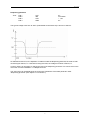
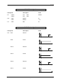
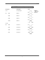
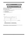
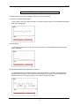
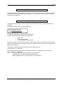
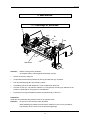
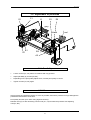
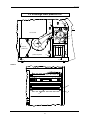
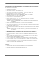
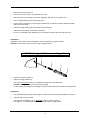
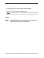
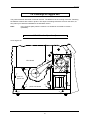
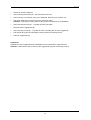
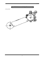
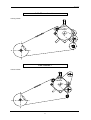
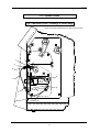
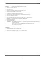
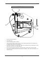
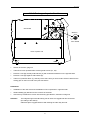
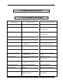
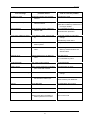
English Service manual Thermal Transfer Printer Desco type 79.69.025 • 12 December 1997 Carl Valentin GmbH • Neckarstraße 78-80 & 94 • 78056 VS-Schwenningen [email protected] • http://www.valentin-carl.de Table of contents Table of contents 1. Block circuits ......................................................................................................................................1 1.1. Block circuit CPU ..................................................................................................................1 1.2. Block circuit power unit .........................................................................................................2 1.3. Wiring diagram......................................................................................................................3 2. Electronics ..........................................................................................................................................4 2.1. Check points .........................................................................................................................4 2.1.1. Voltage supply power board .................................................................................4 2.1.2. Voltage supply CPU..............................................................................................4 2.1.3. Photocells .............................................................................................................5 2.1.4. Clock signals.........................................................................................................9 2.1.5. Strobe signals .......................................................................................................9 2.1.6. Motor signals.......................................................................................................10 2.1.7. External control inputs / outputs .........................................................................11 2.2. Component parts of CPU....................................................................................................12 2.3. Component parts of power supply......................................................................................13 2.4. Changing of fuses...............................................................................................................14 2.4.1. Primary fuse........................................................................................................14 2.4.2. Secondary fuse ...................................................................................................14 2.5. Service monitor ...................................................................................................................15 2.5.1. Valuation of label parameters .............................................................................15 2.5.2. Error message: label error ..................................................................................16 2.5.3. Error elimination..................................................................................................17 2.5.4. Monitor ................................................................................................................17 3. Mechanics .........................................................................................................................................18 3.1. Exchange of printhead........................................................................................................18 3.2. Adjustment of printhead......................................................................................................19 3.2.1. Parallelity ............................................................................................................19 3.2.2. Pressure..............................................................................................................19 3.3. Cleaning of printhead and pressure roll / increase pressure..............................................20 3.4. Exchange lower pressure roll .............................................................................................22 3.5. Exchange upper ribbon tension roll ....................................................................................24 3.6. Exchange of ribbon unwinding roll......................................................................................25 3.7. Exchange of O-belt .............................................................................................................26 3.8. Exchange of cogged belt ....................................................................................................28 3.8.1. Standard (version 4) ...........................................................................................28 3.8.2. Version: unwinding roll inverse ...........................................................................30 3.8.3. Thermal version ..................................................................................................31 3.8.4. Version 1.............................................................................................................31 3.8.5. Version 2.............................................................................................................32 3.8.6. Version 3.............................................................................................................32 I Table of contents 3.9. To oil and lubricate .............................................................................................................33 3.10. Option cutter .....................................................................................................................34 3.10.1. Moveable cutter / exchange of cutter ledge......................................................34 3.10.2. To adjust cutter .................................................................................................36 3.10.3. Exchange of synchroflex drive..........................................................................37 3.11. Option dispenser...............................................................................................................38 3.12. Option date / time .............................................................................................................39 3.13. Option external inputs / outputs ........................................................................................40 4. Possible sources of error ................................................................................................................41 4.1. Error messages on the display ...........................................................................................41 4.2. General errors.....................................................................................................................44 II Service manual 1. Block circuits 1.1. Block circuit CPU The corresponding plan is available on demand. 1 Service manual 1.2. Block circuit power unit The corresponding plan is available on demand. 2 Service manual 1.3. Wiring diagram The corresponding plan is available on demand. 3 Service manual 2. Electronics 2.1. Check points 2.1.1. Voltage supply power board check point description value JP9 JP9 JP9 PIN 1,2,3 PIN 4,5 PIN 6,7,14 VCC VDD GND 5V 5V 0V JP7 JP7 PIN 1-4 PIN 5-8 VH GND 18V 0V JP6 PIN 3 12V 12V JP5 PIN1 VM 29V R30 right PIN VG 29V R30 left PIN VR 11,5V 2.1.2. Voltage supply CPU check-point description value JP4 JP4 JP4 JP4 JP4 VCC VDD GND SUPPLY 1 12V 5V 5V 0V 14V 12V PIN 1,2 PIN 4,5 PIN 6,7,14 PIN 8 PIN 9,10 4 Service manual 2.1.3. Photocells Label photocell: Transmission JP10: PIN 1 PIN 2 PIN 3 PIN 4 VSS INP INP GND ~1,2V } see below 0V Depending on the transparency of the label res. backing paper the voltage at the input of the AD-converter is changing. In sketch 1 a typical voltage wave form at "INP" is shown (measurable at V23 PIN3 too). In case the adjusted value of of the sending current of the photocell is not sufficient, e.g. when using extremely thick or thin backing paper, it can be adjusted by changing P2. Rotation to the right adjustment for thick backing paper Rotation to the left adjustment for thin backing paper. The "INP"-level can be displayed in the menu item "Parameter of the label photocell" under "Transmission photocell" (see chapter "2.5.4. Monitor"). measurement of photocell 5 Service manual Label photocell: reflection JP11: PIN 1 PIN 2 PIN 3 PIN 4 VCC INP VSS GND 5V see sketch ~ 2V 0V The voltage wave form at "INP" is similar to the one described under A. It has to be considered that the marking for the reflection photocell must be in a distance of 32,5 mm to the interior rim, so that the photocell recognizes the marking. The "INP"-level can be displayed in the menu item "Parameter of the photocell" under "Reflection photocell" (see chapter "2.5.4. Monitor"). The marking should have a size of at least 7 mm x 3 mm or bigger. 6 Service manual Dispensing photocell JP12: PIN 1 PIN 2 PIN 3 PIN 4 VCC INP VSS GND 5V see sketch ~ 1,2V 0V The typical voltage wave form at "INP" (measurable at V23 PIN 5 too) is shown in sketch 3. As standard a level of 2,6 V is adjusted. If a label is under the dispensing photocell, the level at "INP" must be higher than 2,6 V. If the label is being removed, the voltage must lower under 2,6 V. In some cases it is necessary to change the level of the dispensing photocell. This can be done in the menu item "Printer initialization - LS-Dispenser level". The "INP"-level can be displayed in the menu item "Parameter of the label photocell" under "Dispensing photocell" (see chapter "2.5.4. Monitor"). 7 Service manual Ribbon control JP9: PIN 1 PIN 2 PIN 3 PIN 4 VCC INP VSS GND 5V High res. Low ~ 1,2V 0V The photocell "ribbon control" checks if the ribbon is moving. By that alterate high- and low signals are measurable at "INP", which should have a ratio as much as possible of 1:1. (The ribbon control works with a ratio of 1:2, too). The photocell has to be adjusted and should be fixed as shown in the sketch below. As long as the photocell sends light onto the inner shaft, "High" results. In case the photocell sends light onto the flexible shaft (black), "Low" results. The "INP"-level can be displayed in the menu item "Parameter of the photocell" under "transfer ribbon photocell" (Hi or Lo) (see chapter "2.5.4. Monitor"). Attention: Inner shaft should not be soiled. 8 Service manual 2.1.4. Clock signals check point description value U8 PIN78 PIN79 CLK CLK 20MHz U25 PIN3 PIN5 RESET RESET 0V ~ 5V U11 PIN3 NMI 0V CPU CPU 2.1.5. Strobe signals check point description U24 Strobe1 PIN7 value 5V t PIN9 Latch1 5V t PIN12 Strobe2 5V t PIN14 Latch2 5V t PIN16 Strobe3 5V t PIN17 Latch3 5V t 9 Service manual 2.1.6. Motor signals check point (CPU) description U19 VOR A PIN15 value Motor ein Motor aus 5V t PIN12 VOR B 5V t PIN9 FR VOR 5V t "VOR A" and "VOR B" are two rectangular signals by 90° displaced phases. check point (power supply) description value JP9 PIN15 PIN16 VOR A VOR B (see above) PIN17 FR VOR 10 Service manual 2.1.7. External control inputs / outputs check point description 4 x IN ext. input pulse U12 PIN4 INPUT 1 PIN6 INPUT 2 PIN8 INPUT 3 PIN10 INPUT 4 PIN2 OUTPUT 1 PIN3 OUTPUT 2 PIN6 OUTPUT 3 PIN7 OUTPUT 4 value 12-24V 4 x OUT U22 11 Service manual 2.2. Component parts of CPU The corresponding plan is available on demand. 12 Service manual 2.3. Component parts of power supply The corresponding plan is available on demand. 13 Service manual 2.4. Changing of fuses 2.4.1. Primary fuse rear panel The primary fuse is in the power line filter block and accessible from outside. After plugging out the cover can be removed. There behind you will find the fuse-switch, which has to be drawn near to change the fuse. F: fine-wire fuse T1,0A power line filter block F3 2.4.2. Secondary fuse Attention: The machine should only be opened by competent staff. Plug out before removing the left cover. After removing the left cover a further cover plate is visible. There behind you will find the power supply board with 2 secondary fuses. F1: fine-wire fuse T 1,0 A F2: fine-wire fuse T 10,0 A fuse for 5 V and 12 V supply fuse for motor voltage (29 V) and burning voltage (18 V) motor F2 F1 transformer 14 Service manual 2.5. Service monitor 2.5.1. Valuation of label parameters In function menu "Parameter of label photocell" you will find the service monitor, by which the photocells can be checked res. adjusted. When measuring the labels the values will be displayed in the first line, thereby the following measured voltages are shown: A: B: C: D: E: absolute minimum (measured on backing-paper) smallest maximum (measured on label) upper switching level lower switching level highest measured voltage (most ~5 V) The sketch illustrates the voltage wave form of the label photocell while measuring the labels. The difference between "A" and "B" should be at least 1,5 V. 15 Service manual 2.5.2. Error message: label error Possible reasons of this error message "Label error" are the following: Too thick res. opaque backing paper In this case the value of A will be too high. This means, that the printer cannot distinguish between label and backing paper. Very thin labels In this case the value of E res. B is too low, so the printer cannot distinguish between backing paper and labels. Pre-printed label with strong differences in contrast Pre-printed labels are a particular problem. Here the fluctuations of voltage on the label while measuring are very high. In this case the value of B will be very small. In case the difference between B and A is too small, the printer is not able to measure the label. 16 Service manual 2.5.3. Error elimination In case the photocell already had been adjusted so that the difference between A and B has received the highest possible value (as described in chapter "2.1.3. Photocells"), the "sensitivity of the label photocell" can be adjusted. 2.5.4. Monitor After activating the key again in menu "Parameter of label photocell", the photocell monitor will be activated. On the display of the printer the following appears: The digit represents the measured voltage; the black bar represents the measured voltage as graph; the last character shows the position of the photocell: + 0 above label above backing paper at the edge label - backing-paper The monitor serves to check the label photocell to its function. As well it is possible to move the label manually under the photocell to obtain an idea of the voltage wave form and to be able to judge, if the label can be measured. The difference of backing-paper and label should be higher than 1,5 V (see chapter "2.1.3. Photocells"). After activating the key again "Reflexion photocell" appears for checking the reflexion photocell (see chapter "2.1.3. Photocells") then: "Dispensing photocell 3" (see chapter "2.1.3. Photocells") "Printhead temp. XX degrees (Printhead temperature) "Ribbon photocell" (Hi or Lo) (see chapter "2.1.3. Photocells") 17 Service manual 3. Mechanics 3.1. Exchange of printhead D grey B1 black red B2 C1 thermistor E C2 A Attention: Before working at the printhead: Accomplish safety control against electrostatic charge! Switch off machine, plug out! Lift printhead bracket with printhead by turning knurled knob (A) clockwise. Pull off printhead plug (B1, B2) including cables. Considering machines with dispenser: screw off dispenser photocell. Unscrew screws (C1, C2) about 3 rotations by a ring spanner, thereby pay attention to the position of printhead for the purpose of reinstallation. Press latch lever (D) backwards and draw off printhead (E) to the front. Installation: Install the new printhead with placed screws (C) in opposite order. Attention: Do not touch the contacts of the printhead While installing pay attention that termistor cable lies in the cut-out provided for Pay attention to the correct fit of the printhead (guiding!) 18 Service manual 3.2. Adjustment of printhead C1 D1 E C2 D2 grey black red B1 A1 B2 A2 3.2.1. Parallelity Loosen screws (A1, A2) about 1/2 rotations with ring spanner. Adjust parallelity by screws (B1, B2). Depending on the print quality adjust more, until the print quality is correct. Tighten screws (A1, A2) again. 3.2.2. Pressure Avoid increase of printhead pressure as much as possible, because a pressure too high damages the printhead and decreases its life time. Print quality too faint (even when using highest contrast): Release lever (E) or after loosening counter nuts (C1, C2) increase the pressure with adjusting nuts (D1, D2). 19 Service manual 3.3. Cleaning of printhead and pressure roll / increase pressure Principally it is advisable and necessary to clean the printhead in regular intervals depending on the printer's operating hours and its environment (e.g. dust etc.). With a test print it can be easily found out whether the printhead is soiled or defective. a) printhead is o.k. b) printhead is defective/soiled While cleaning the print head, the printer has to be switched off ! 1 3 2 4 20 Service manual Turn up printhead bracket by the rotary button (4) as if loading labels. Press lever (1) to the back. The printhead (2) automatically turns up. If this does not happen please turn up the printhead carefully. Clean the lower surface of the printhead only with dry cleaning solvent. As expedient a closewoven cotton cloth is recommended. In case this procedure is not sufficient the printhead can be cleaned with a special cleaning foil (to be obtained from us). After cleaning clap the printhead down until lever (1) snaps again. Attention: Scratching, strong rubbing or using rough or hard subjects for cleaning is absolutely to be avoided, as the printhead is very sensitive. Cleaning of pressure roll: In certain intervals the pressure roll has to be cleaned with spirit (dust, soil etc.). Increase pressure: In case of insufficient quality of print, pull up lever (3) (e.g. when using carton, thick label material or very small fonts). 21 Service manual 3.4. Exchange lower pressure roll G5 G4 I1 H3 E CPU board H4 Z motor H2 I2 L F J1 H1 K J2 C4 C3 B G3 transformer cover of power unit M D3 D4 G2 G1 C1 power unit plate C2 D1 A1 D2 A2 View Z: N O P 22 Service manual In connection with the exchange of the pressure roll, the complete printer mechanics should be oiled and lubricated (see chapter "3.9. To oil and lubricate"), as the lubrication points are free accessible after the following instructing steps. Switch off machine, plug out! After removing screws (A1, A2), take off left cover. After removing 4 screws (B), only one is displayed, take off cover of power unit. Pull off all cable plug connectors from power unit plate. Attention: Take notice of the position of plugs for the purpose of reinstallation! After removing nuts (C1 - C4), take off power unit plate. Loosen screws (D1 - D4) and take off transformer. Pull off cable plug connectors JP9 / JP10 / JP12 / JP14 / (JP11) from CPU board. (Specifications see circuit board and cable) Attention: In spite of specification take notice of the position of the plugs for the purpose of reinstallation! Pull off cogged belt (E) from return pulley (F) and remove it from rewinder (M). After removing the hexagonal head screw take off return pulley (F). Therefore hold return pulley at the opposite side and take it off, too. After removing nuts and screws (G1 - G5) take off the complete print mechanics to the right hand side. Attention: While screwing off the nuts and screws pay attention to the print mechanics, so it won't fall down. After removing screws (H1 - H4) take off the motor. Thereby remove short cogged belt (L). Attention: While taking off the motor, the two Delrin belt drives (I1, I2) will be loosened. Loosen locking screws (J1, J2) and take out pair of belt drives (K) with spacer piece and ball bearing. Take off locking washer (N) and ball bearing (O) on the other side of the shaft. Then take out downwards pressure roll (P) of the print mechanics. As much as possible clean the ball bearing in dry cleaning solvent and then lubricate new! Oil and lubricate the complete print mechanics according to chapter "3.9. To oil and lubricate". If necessary the upper ribbon tension roll can be exchanged at the same time according to chapter "3.5. Exchange upper ribbon tension roll". Installation: Installation of the new roll and reinstallation of all components in opposite order. Regard that locking screw (J1) meets milled surface of the roll. 23 Service manual 3.5. Exchange upper ribbon tension roll F E1 Z E2 C CPU-board motor D B transformer cover of power unit power unit plate A1 A2 View Z: H G 24 Service manual Switch off machine, plug out! After removing screws (A1, A2), take off left cover. After removing 4 screws (B), only one is displayed, take off cover of power unit. Pull off cogged belt (C) from return pulley (D). Loosen locking screws (E1, E2) and pull off belt drive (F) with belt, spacing washer and ball bearing from the shaft. Take off locking washer (G) on the other side of the shaft. Take out tension roll (H) of the print mechanics. As much as possible clean ball bearing in dry cleaning solvent and then lubricate new. Installation: Installation of the new roll and reinstallation of all components in opposite order. Attention: Take notice of the correct fit of the cogged belt (C)! 3.6. Exchange of ribbon unwinding roll D C B A Switch off machine, plug out! Take off locking washer (A). Turn roll (B) clockwise and pull it outwards the pillar (D) at the same time. Attention: Danger of injury at thin spring steel plate. In case spring (C) remains in unwinding roll, pull it outside with rotary motion at the same time. Installation: Lubricate pillar (D) and push spring approx. to the middle of the pillar (if possible a new one). Lubricate spring from outside. Turn the ribbon unwinding roll by clockwise rotations onto the spring. After approx. 10 rotations press the roll far inside and fix locking washer. 25 Service manual 3.7. Exchange of O-belt B D E C G F A 26 Service manual Switch off machine, plug out! Open right cover. By turning the knurled knob (A) counter clockwise, press down the printhead. Take off locking washer (B). Pull off O-belt (C) from ribbon unwinding roll (D) and take it out. Carefully lever the printhead bracket (F), according to the sketch with screwdriver (E) (e.g. size 6) to the front. At the same time pull off manually or with a second screwdriver O-belt from synchroflex drive (G). Installation: Installation of the O-belt in opposite order. Attention: Lever away printhead bracket (F) just as much as necessary, so nothing gets bent. Pay attention to the correct running of the O-belt (see sketch). No lubricant onto O-belt (if necessary clean it). 27 Service manual 3.8. Exchange of cogged belt The printer had been delivered in several versions. The difference is the running of the belt. Following the different versions are shown in picture. The steps to exchange a belt are as much the same, so they will only be described detailed for the standard version. Note: In the need of spare parts the versions 1-3 should be converted to version 4 (standard)! 3.8.1. Standard (version 4) since august '93 G F4 D CPU-board motor E F1 F2 C3 C4 B transformer cover of power unit C2 C1 power unit board A1 A2 28 F3 Service manual Switch off machine, plug out! After removing the screws (A1, A2), take off the left cover. After removing 4 screws (B), only one is displayed, take off cover of power unit. Pull off all cable plug connectors from the power unit plate. Attention: Take notice of the position of the plugs for the purpose of reinstallation! After removing the nuts (C1 - C4) take off power unit plate. Remove defect cogged belt (D). After removing screws (F1 - F4) take off motor. Thereby take off short cogged belt. Pull off belt drive (G) from shaft after screwing off the two locking screws. Take off cogged belt (D). Installation: Installation of new cogged belt and reinstallation of all components in opposite order. Attention: Take notice of the correct fit of the cogged belt (D) (see concerning version). 29 Service manual 3.8.2. Version: unwinding roll inverse running of belt: motor 30 Service manual 3.8.3. Thermal version running of belt: motor 3.8.4. Version 1 running of belt: motor 31 Service manual 3.8.5. Version 2 running of belt: motor regard marking 3.8.6. Version 3 since December '92 until July '93 running of belt: motor 32 Service manual 3.9. To oil and lubricate Following all oil and lubricate points of the printer are shown: Attention: It is advisable to lubricate and to oil printer completely twice a year. 33 Service manual 3.10. Option cutter 3.10.1. Moveable cutter / exchange of cutter ledge Note: The points marked are to be oiled 3 times a year ! I J L A B K D E C motor H G A F molykote oil 34 Service manual Attention: Danger of injury while working at the cutter! Switch off machine, plug out! Open right cover. Remove 4 screws (A) and take off front plate above (C). Remove nut (B) and take off holding shaft. Fix spring (D) at magnetic adjusting screw (E). Take off locking washer of the inner side of bearing lever of cutter (F). Pull bearing shaft (G) outwards. At the same time take off the complete moveable cutter (F + H) to the front. Attention: Do not loose 2 spacer rings on the bearing shaft! Remove two screws (I). Take off cutting ledge (J). Attention: Pay attention to the position of slide bearing (K) with integrated intermediate (L), in case they will loosen. On the right side of the cutter ledge the intermediate loosens, too. Pay attention to the position. Installation: Install (sharpened) cutter in opposite order. Adjust cutter according to chapter "3.10.2. To adjust cutter". 35 Service manual 3.10.2. To adjust cutter A D C motor B Switch off machine, plug out! Open right cover. Loosen 2 screws (A) about 1 rotation. Insert screwdriver (B) according to sketch. (control: While pressing down the screwdriver the moveable cutter (C) has to move upwards.) Press down screwdriver, so the left upper edge of the moveable cutter (C) stands about 0,5 mm above the lower edge of the cutting ledge (D). Move the cutting ledge (D) towards the moveable cutter (C) and fix both screws (A) again. Insert a piece of paper or label and check with the screwdriver, if the cutter cuts correctly. If not, repeat the steps. 36 Service manual 3.10.3. Exchange of synchroflex drive F B D E CPU-board direction motor C 180° rotated cover of power unit A1 A2 Switch off machine, plug out! Take off left cover upwards after removing both screws (A1, A2). Remove screw (B), thereby hold bed bolt (C) with a slotted screwdriver on the opposite side. Remove screw (D) together with bracket (E). Take out synchroflex drive (F), whereby at the same time you have to take off the O-belt from the driving gear on the inner side of the print mechanics. Installation: Installation of the new drive and reinstallation of all components in opposite order. While installing pay attention to the correct fit of the belts. Insert the synchroflex drive centric into the boring provided for, otherwise it will grind. Attention: The integrated grooved ball bearing has to catch the cogged belt drive clockwise (according to the sketch) Otherwise place cogged belt drive with bearing the other way around! 37 Service manual 3.11. Option dispenser In case a label has been winded-up around the pressure roll, it may not be scratched off with a knife. The label has to be torn off manually as much as possible, and possibly remains of adhesive have to be wiped off with spirit. The roll may not be damaged on its surface. How to load labels in dispensing mode see the corresponding operating manual. 38 Service manual 3.12. Option date / time U7: RTC 72421A BT1 + Installation: Switch off printer and remove CPU. Insert IC U7 (RTC 72421A) in therefore provided socket. Hereby pay attention to correct positioning. When soldering in battery pay attention to direction of polarization. Reinstallation of CPU. Attention: Use only original parts. 39 Service manual 3.13. Option external inputs / outputs PC 849 (2x) Installation: Switch off and open printer. Remove cover sheet on rear panel (cutout for I/O plug). Installation of I/O-plug, whereby the plug has to be installed below and the socket above. Insert IC PC 849 in socket. Attention: U 21 has to be adjusted differently from U 22 (see PIN 1 of socket). Attention: Use only original parts. 40 Service manual 4. Possible sources of error 4.1. Error messages on the display error message possible causes how to solve the problem printhead temperature printhead too hot wait until printhead has cooled down line too high position of line outside of label place line in a lower position (Y) check rotation, font line too low position of line outside of label place line in a higher position (Y) check rotation, font font not installed selected font not existant check font and change character not in font character not included in font change font entry of consecutive numbers incorrect entry of consecutive numbering check entry of consecutive numbering and change magnification code entered SC factor is invalid check SC factor and change width lines or boxes line projects label rim change line graphic data graphic not found on MC selected graphic not stored on Memory-Card store the graphic on the MemoryCard check digit wrong entered check digit is faulty in check recalculate check digit digit control check code data incorrect number of digits entered number of characters invalid check code data incorrect entry of code mask statement code faulty check code statement internal font error faulty font Please contact your distributor label or printhead error no labels load labels printhead not closed close printhead 41 Service manual error message possible causes how to solve the problem no Memory-Card no Memory-Card or not correctly entered enter Memory-Card not enough memory max. storage space of MemoryCard is reached use a new Memory-Card "Write Protect"-switch of MemoryCard is "ON" use a new Memory-Card wrong Memory-Card entered (256 K) check type of Memory-Card and change write protected wrong type of Memory-Card delete files on Memory-Card that are no longer needed deactivate write protection enter Memory-Card 128 K label exists already label name already stored on Memory-Card change label name no label exists label name not stored on MemoryCard search through the contents of the Memory-Card and select the desired name unknown error internal storage error on MemoryCard store data anew serial EEPROM max. write cycles reached change EEPROM printing active when copying a Memory-Card hilst print command is active wait until printer is ready command statement wrong invalid command statement check command statement and change overrun receiving byte is written though it has not been cleared yet transmit anew framing wrong Baudrate check Baudrate and change parity wrong parity check parity and change incorrect password entered code is not correct enter correct code entered code when formatting a Memory-Card is not correct enter correct code 42 use a new Memory-Card Please contact your distributor Service manual error message possible causes how to solve the problem number of lines in printing mode "continuous labels" number of lines too low correct number of lines interface protocol incorrect setting of SOH and ETB change interface protocol ribbon or printhead error no transfer ribbon load transfer ribbon printhead not closed close printhead no cutter available print mode "Cutter OFF" or connect cutter cutter errot cutter will not be switched off (cutter Please contact your distributor photocell or micro-switch are defective) power failure please wait loss of voltage supply check power line and surroundings no RTC installed no RTC ram add RTC ram RTC-mode RTC entry incorrect check RTC entry and change RTC-format string RTC format string faulty check RTC format string and change dispenser photocell defect or not connected defective dispensing photocell exchange dispenser photocell dispensing photocell not connected connect photocell 43 Service manual 4.2. General errors Generally speaking in case of an error you should check, if all fuses are in order (see chapter "2.4. Changing of fuses"). error message bad or wrong printout no print possible causes how to solve the problem contrast adjusted wrong adjust contrast in menu item "Printer parameters"r" printhead or pressure roll sticky / dirty clean with methylated spirits printhead defective, pressure roll is run in exchange defective parts see chapter "3.1." and "3.4" driver module defective exchange U24 single dots are missing exchange or clean printhead printhead is badly adjusted adjust printhead see chapter "3.2. Adjustment of printhead" incorrect voltage supply measure voltage of printhead, eliminate error driver module defective exchange U24 no data transmission interface module defective RS232: exchange U37 Centronics: interface protocol adjusted wrong exchange U43 or / and U36 correct interface protocol Baudrate adjusted wrong check adjustment of Baudrate (sender and receiver have to be adjusted the same) interface cable (external) defective res. wrong check cable Memory-Card will not be read snap fastener at plug-in defective / does not snap in exchange Memory-Card pedestal U9 no data onto Memory-Card battery empty exchange battery order-no.: 27.02.002 wrong entry via external keyboard keyboard defective exchange keyboard display is dark (although printer runs) display defective exchange display activation wrong voltage supply is missing exchange U49 44 check fuses and supply line Service manual error message no entry possible via foil keyboard possible causes foil keyboard defective exchange foil keyboard flex print harness of foil keyboard is not plugged in correctly insert cable carefully in JP15 earthing strap is not connected connect earthing strap transport irregular / labels run photocell dirty through without stopping photocell defective clean photocell photocell adjusted wrong no transport of labels how to solve the problem cogged belt torn exchange photocell see chapter "2.1.3. Photocells" exchange cogged belt motor res. motor activation defective check motor see chapter "2.1.6. Motor signals" labels are not rewinded ribbon is not rewinded ventilator is not running RTC is not running cogged belt torn exchange cogged belt sliding clutch in rewinding roll adjusted too weak adjust sliding clutch cogged belt torn exchange cogged belt O-belt torn exchange O-belt O-belt drive defective (only cutter !) exchange drive ventilator defective exchange ventilator voltage missing emeasure voltage, eliminate error battery defective exchange battery RTC defective exchange RTC cutter does not cut (correctly) cutter adjusted wrong adjust cutter see chapter "3.10.2. To adjust cutter" cutting edge blunt exchange cutter cutter dirty clean cutter photocell (cutter) dirty or defective clean or exchange photocell motor defective exchange motor label dispenser is not working dispensing photocell dirty / defective clean / exchange dispensing photocell control input defective exchange U21 label transport defective see above: 'no label transport' It is recommended to test the printout from time to time to check if all dots are working properly. 45