1
R
Appendix C
PicoBlaze Instruction Set and Event
Reference
This appendix provides a detailed operational description of each PicoBlaze instruction
and the Interrupt and Reset events, including pseudocode for each instruction. The
pseudocode assumes that all variable to the right of an assignment symbol (Å) have the
original value before the instruction is executed. The values for variables to the left of an
assignment symbol are assigned at the end of the instruction and all assignments occur in
parallel, similar to VHDL.
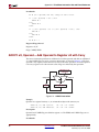
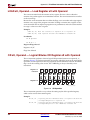
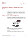
ADD sX, Operand —Add Operand to Register sX
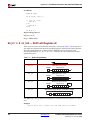
The ADD instruction performs an 8-bit addition of two operands, as shown in Figure C-1.
The first operand is any register, which also receives the result of the operation. A second
operand is also any register or an 8-bit constant value. The ADD instruction does not use the
CARRY as an input, and hence, there is no need to condition the flags before use. Flags are
affected by this operation.
Register sY or
Literal kk
Carry Out
CARRY
Register sX
UG129_aC_01_051604
Figure C-1:
ADD Operation
Example
Operand is a register location, sY, or an immediate byte-wide constant, kk.
ADD sX, sY; Add register.
ADD sX, kk; Add immediate.
sX = sX + sY.
sX = sX + kk.
Description
Operand is added to register sX. The ZERO and CARRY flags are set appropriately.
PicoBlaze 8-bit Embedded Microcontroller
UG129 (v1.1) June 10, 2004
www.xilinx.com
1-800-255-7778
93
R
Appendix C: PicoBlaze Instruction Set and Event Reference
Pseudocode
sX Å (sX + Operand) mod 256; always an 8-bit result
if ( (sX + Operand) > 255 ) then
CARRY Å 1
else
CARRY Å 0
endif
if ( ((sX + Operand) = 0) or ((sX + Operand) = 256) ) then
ZERO Å 1
else
ZERO Å 0
endif
PC Å PC + 1
Registers/Flags Altered
Registers: sX, PC
Flags: CARRY, ZERO
ADDCY sX, Operand —Add Operand to Register sX with Carry
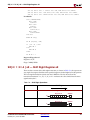
The ADDCY instruction performs an addition of two 8-bit operands and adds an additional
‘1’ if the CARRY flag was set by a previous instruction, as shown in Figure C-2. The first
operand is any register, which also receives the result of the operation. A second operand
is also any register or an 8-bit constant value. Flags are affected by this operation.
Register sY or
Literal kk
Carry Out
CARRY
Carry In
Register sX
UG129_aC_02_051604
Figure C-2:
ADDCY Instruction
Example
Operand is a register location, sY, or an immediate byte-wide constant, kk.
ADDCY sX, sY; Add register.
ADDCY sX, kk; Add immediate.
sX = sX + sY + CARRY
sX = sX + kk + CARRY
Description
Operand and CARRY flag are added to register sX. The ZERO and CARRY flags are set
appropriately.
Pseudocode
94
www.xilinx.com
1-800-255-7778
PicoBlaze 8-bit Embedded Microcontroller
UG129 (v1.1) June 10, 2004
R
AND sX, Operand — Logical Bitwise AND Register sX with Operand
if (CARRY = 1) then
sX Å (sX + Operand + 1) mod 256; always an 8-bit result
else
sX Å (sX + Operand) mod 256
; always an 8-bit result
end if
if ( (sX + Operand + CARRY) > 255 ) then
CARRY Å 1
else
CARRY Å 0
endif
if ( ((sX + Operand + CARRY) = 0) or ((sX + Operand + CARRY) = 256) )
then
ZERO Å 1
else
ZERO Å 0
endif
PC Å PC + 1
Registers/Flags Altered
Registers: sX, PC
Flags: CARRY, ZERO
Notes
pBlazIDE Equivalent: ADDC
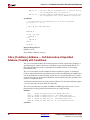
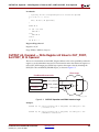
AND sX, Operand — Logical Bitwise AND Register sX with
Operand
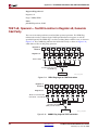
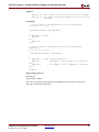
The AND instruction performs a bitwise logical AND operation between two operands, as
shown in Figure C-3. The first operand is any register, which also receives the result of the
operation. A second operand is also any register or an 8-bit immediate constant. The ZERO
flag is set if the resulting value is zero. The CARRY flag is always cleared by an AND
instruction.
Register sY
Literal kk
Register sX
7
7
6
6
5
5
4
4
3
3
2
2
1
1
0
0
UG129_aC_06_051604
Figure C-3:
AND Operation
The AND operation can be used to perform tests on the contents of a register. The status of
the ZERO flag then controls the flow of the program.
Examples
PicoBlaze 8-bit Embedded Microcontroller
UG129 (v1.1) June 10, 2004
www.xilinx.com
1-800-255-7778
95
R
Appendix C: PicoBlaze Instruction Set and Event Reference
AND sX, sY
AND sX, kk
;
;
;
;
Logically AND the
the corresponding
Logically AND the
the corresponding
individual bits of register sX with
bits in register sY
individual bits of register sX with
bits in the immediate constant kk
Pseudocode
; logically AND the corresponding bits in sX and the Operand
for (i=0; i<= 7; i=i+1)
{
sX(i) Å sX(i) AND Operand(i)
}
CARRY Å 0
if (sX = 0) then
ZERO Å 1
else
ZERO Å 0
end if
PC Å PC + 1
Registers/Flags Altered
Registers: sX, PC
Flags: ZERO, CARRY is always 0
CALL [Condition,] Address — Call Subroutine at Specified
Address, Possibly with Conditions
The CALL instruction modifies the normal program execution sequence by jumping to a
specified program address. Each CALL instruction must specify the 10-bit address as a
three-digit hexadecimal value or a label that the assembler resolves to a three-digit
hexadecimal value.
The CALL instruction has both conditional and unconditional variants. A conditional
CALL is only performed if a test performed against either the ZERO flag or CARRY flag is
true. If unconditional or if the condition is true, the CALL instruction pushes the current
value the PC to the top of the CALL/RETURN stack. Simultaneously, the specified CALL
location is loaded into the PC.
A subroutine function must exist at the specified address. The subroutine function requires
a RETURN instruction to return from the subroutine.
The CALL instruction does not affect the ZERO or CARRY flags. However, if a CALL is
performed, the resulting subroutine instructions may modify the flags.
Examples
CALL
CALL
CALL
CALL
CALL
C,
NC,
Z,
NZ,
MYSUB;
MYSUB;
MYSUB;
MYSUB;
MYSUB;
Unconditionally call MYSUB subroutine
If CARRY flag set, call MYSUB subroutine
If CARRY flag not set, call MYSUB subroutine
If ZERO flag set, call MYSUB subroutine
If ZERO flag not set, call MYSUB subroutine
Condition
96
www.xilinx.com
1-800-255-7778
PicoBlaze 8-bit Embedded Microcontroller
UG129 (v1.1) June 10, 2004
R
COMPARE sX, Operand — Compare Operand with Register sX
Depending on the specified Condition, the program calls the subroutine beginning at the
specified Address. If the specified Condition is not met, the program continues to the next
instruction.
Table C-1:
CALL Instruction Conditions
Condition
<none>
C
NC
Z
NZ
Description
Always true. Call subroutine unconditionally.
CARRY = 1. Call subroutine if CARRY flag is set.
CARRY = 0. Call subroutine if CARRY flag is cleared.
ZERO = 1. Call subroutine if ZERO flag is set.
ZERO = 0. Call subroutine if ZERO flag is cleared.
Pseudocode
if (Condition = TRUE) then
; push current PC onto top of the CALL/RETURN stack
; TOS = Top of Stack
TOS Å PC
; load PC with specified Address
PC Å Address
else
PC Å PC + 1
endif
Registers/Flags Altered
Registers: PC, CALL/RETURN stack
Flags: Not affected
Notes
The maximum number of nested subroutine calls is 31 levels, due to the depth of the
CALL/RETURN stack.
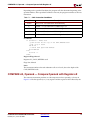
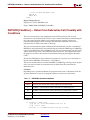
COMPARE sX, Operand — Compare Operand with Register sX
The COMPARE instruction performs an 8-bit comparison of two operands, as shown in
Figure C-4. The first operand, sX, is any register and this register is NOT affected by the
PicoBlaze 8-bit Embedded Microcontroller
UG129 (v1.1) June 10, 2004
www.xilinx.com
1-800-255-7778
97
R
Appendix C: PicoBlaze Instruction Set and Event Reference
COMPARE operation. The second operand is also any register or an 8-bit immediate
constant value. Only the flags are affected by this operation.
Register sX
A
B
Register sY or
Literal kk
A
B
A=B?
B>A?
ZERO
CARRY
UG129_aC_05_051604
Figure C-4:
COMPARE Operation
Register sX is compared against Operand. The ZERO flag is set when Register sX and
Operand are identical. The CARRY flag is set when Operand is larger than Register sX,
where both Operand and Register sX are evaluated as unsigned integers.
Example
Operand is a register location, sY, or an immediate byte-wide constant, kk.
COMPARE sX, sY; Compare sX against sY.
COMPARE sX, kk; Compare sX against immediate constant, kk.
Pseudocode
if ( Operand > sX ) then
CARRY Å 1
else
CARRY Å 0
endif
if ( sX = Operand ) then
ZERO Å 1
else
ZERO Å 0
endif
PC Å PC + 1
Registers/Flags Altered
Registers: PC only. No data registers affected.
Flags: CARRY, ZERO
Notes
pBlazIDE Equivalent: COMP
The COMPARE instruction is only supported on PicoBlaze microcontrollers for Spartan-3,
Virtex-II, and Virtex-II Pro FPGAs.
98
www.xilinx.com
1-800-255-7778
PicoBlaze 8-bit Embedded Microcontroller
UG129 (v1.1) June 10, 2004
R
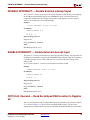
DISABLE INTERRUPT — Disable External Interrupt Input
DISABLE INTERRUPT — Disable External Interrupt Input
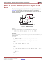
The DISABLE INTERRUPT instruction clears the interrupt enable (IE) flag. Consequently,
the PicoBlaze microcontroller ignores the INTERRUPT input. Use this instruction to
temporarily disable interrupts during timing-critical code segments. Use the ENABLE
INTERRUPT instruction to re-enable interrupts.
Example
DISABLE INTERRUPT; Disable interrupts
Pseudocode
INTERRUPT_ENABLE Å 0
PC Å PC + 1
Registers/Flags Altered
Registers: PC
Flags: INTERRUPT_ENABLE
Notes
PBlazIDE Equivalent: DINT
ENABLE INTERRUPT — Enable External Interrupt Input
The ENABLE INTERRUPT instruction sets the interrupt enable (IE) flag. Consequently, the
PicoBlaze microcontroller recognizes the INTERRUPT input. Before using this instruction,
a suitable interrupt service routine (ISR) must be associated with the interrupt vector
address, 3FF.
Never issue the ENABLE INTERRUPT instruction from within an ISR.
Example
ENABLE INTERRUPT; Enable interrupts
Pseudocode
INTERRUPT_ENABLE Å 1
PC Å PC + 1
Registers/Flags Altered
Registers: PC
Flags: INTERRUPT_ENABLE
Notes
PBlazIDE Equivalent: EINT
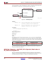
FETCH sX, Operand — Read Scratchpad RAM Location to Register
sX
The FETCH instruction reads scratchpad RAM location specified by Operand into register
sX, as shown in Figure C-5. There are 64 scratchpad RAM locations. The two mostsignificant bits of Operand, bits 7 and 6, are discarded and the RAM address is truncated to
PicoBlaze 8-bit Embedded Microcontroller
UG129 (v1.1) June 10, 2004
www.xilinx.com
1-800-255-7778
99
R
Appendix C: PicoBlaze Instruction Set and Event Reference
the least-significant six bits of Operand, bits 5 to bit 0. Consequently, a FETCH operation
from address FF is equivalent to a FETCH operation from address 3F.
64-Byte Scratchpad RAM
DATA_IN[7:0]
FALSE
Register sY or
Literal kk
DATA_OUT[7:0]
Register sX
WRITE_ENABLE
[5:0]
ADDRESS[5:0]
[7]
[6]
UG129_aC_11_051604
Figure C-5:
FETCH Operation
Examples
FETCH sX, (sY) ; Read scratchpad RAM location specified by the
; contents of register sY into register sX
FETCH sX, kk
; Read scratchpad RAM location specified by the
; immediate constant kk into register sX
Pseudocode
sX Å Scratchpad_RAM [Operand[5:0]]
PC Å PC + 1
Registers/Flags Altered
Registers: PC
Flags: None
Notes
pBlazIDE Equivalent: The instruction mnemonic, FETCH, is the same for both KCPSM3
and pBlazIDE. However, the instruction syntax for indirect addressing is slightly different.
The KCPSM3 syntax places parentheses around the indirect address while the pBlazIDE
syntax uses no parentheses.
KCPSM3 Instruction
PBlazIDE Instruction
FETCH sX, (sY)
FETCH sX, sY
The FETCH instruction is only supported on PicoBlaze microcontrollers for Spartan-3,
Virtex-II, and Virtex-II Pro FPGAs.
INPUT sX, Operand — Set PORT_ID to Operand, Read value on
IN_PORT into Register sX
The INPUT instruction sets the PORT_ID output port to either the value specified by
register sY or by the immediate constant kk. The instruction then reads the value on the
IN_PORT input port into register sX. Flags are not affected by this operation.
100
www.xilinx.com
1-800-255-7778
PicoBlaze 8-bit Embedded Microcontroller
UG129 (v1.1) June 10, 2004
R
INTERRUPT Event, When Enabled
Interface logic decodes the PORT_ID address to provide the correct value on IN_PORT.
Examples
INPUT sX, sY ; Read the value on IN_PORT into register sX, set PORT_ID
;
to the contents of sY
INPUT sX, kk ; Read the value on IN_PORT into register sX, set PORT_ID
;
to the immediate constant kk
Pseudocode
PORT_ID Å Operand
sX Å IN_PORT
PC Å PC + 1
Registers/Flags Altered
Registers: sX, PC
Flags: None
Notes
pBlazIDE Equivalent: IN
The READ_STROBE output is asserted during the second CLK cycle of the two-cycle
INPUT operation.
INTERRUPT Event, When Enabled
The interrupt event is not an instruction but the response of the PicoBlaze microcontroller
to an external interrupt input. If the INTERRUPT_ENABLE flag is set, then a recognized
logic level on the INTERRUPT input generates an Interrupt Event. The action essentially
generates a subroutine CALL to the most-significant instruction address, location 1023
($3FF). The currently executing instruction is allowed to complete. Once the PicoBlaze
microcontroller recognizes the interrupt input, the INTERRUPT_ENABLE flag is
automatically reset. The next instruction in the normal program flow is preempted by the
Interrupt Event and the current PC is pushed onto the CALL/RETURN stack. The PC is
loaded with all ones and the program calls the instruction at the most-significant address.
The instruction at the most-significant address must jump to the interrupt service routine
(ISR).
Pseudocode
; only respond to INTERRUPT input if INTERRUPT_ENABLE flag is set
if ( (INTERRUPT_ENABLE = 1)and (INTERRUPT input = High) ) then
; clear the INTERRUPT_ENABLE flag
INTERRUPT_ENABLE Å 0
; push the current program counter (PC) to the stack
; TOS = Top of Stack
TOS Å PC
; preserve the current CARRY and ZERO flags
PRESERVED_CARRY Å CARRY
PRESERVED_ZERO Å ZERO
; load program counter (PC) with interrupt vector ($3FF)
PC Å $3FF
PicoBlaze 8-bit Embedded Microcontroller
UG129 (v1.1) June 10, 2004
www.xilinx.com
1-800-255-7778
101
R
Appendix C: PicoBlaze Instruction Set and Event Reference
endif
Registers/Flags Altered
Registers: PC, CALL/RETURN stack
Flags: CARRY, ZERO, INTERRUPT_ENABLE
Notes
The PicoBlaze microcontroller asserts the INTERRUPT_ACK output on the second CLK
cycle of the two-cycle Interrupt Event, as shown in Figure 4-3, page 45. This signal is
optionally used to clear any hardware interrupt flags.
The programmer must ensure that a RETURNI instruction is only performed in response to
a previous interrupt. Otherwise, the PC stack may not contain a valid return address.
Do not use the RETURNI instruction to return from a subroutine CALL. Instead, use the
RETURN instruction.
Because an interrupt event may happen at any time, the values of the CARRY and ZERO
flags cannot be predetermined. Consequently, the corresponding Interrupt Service Routine
(ISR) must not depend on specific values for the CARRY and ZERO flags.
102
www.xilinx.com
1-800-255-7778
PicoBlaze 8-bit Embedded Microcontroller
UG129 (v1.1) June 10, 2004
R
JUMP [Condition,] Address — Jump to Specified Address, Possibly with Conditions
JUMP [Condition,] Address — Jump to Specified Address,
Possibly with Conditions
The JUMP instruction modifies the normal program execution sequence by jumping to a
specified program address. Each JUMP instruction must specify the 10-bit address as a
three-digit hexadecimal value or a label that the assembler resolves to a three-digit
hexadecimal value.
The JUMP instruction has both conditional and unconditional variants. A conditional JUMP
is only performed if a test performed against either the ZERO flag or CARRY flag is true. If
unconditional or if the condition is true, the JUMP instruction loads the specified jump
address into the Program Counter (PC).
The JUMP instruction does not affect the CALL/RETURN stack.
The JUMP instruction does not affect the ZERO or CARRY flags.
Example
JUMP
JUMP
JUMP
JUMP
JUMP
C,
NC,
Z,
NZ,
NEW_LOCATION;
NEW_LOCATION;
NEW_LOCATION;
NEW_LOCATION;
NEW_LOCATION;
Unconditionally jump to NEW_LOCATION
If CARRY flag set, jump to NEW_LOCATION
If CARRY flag not set, jump to NEW_LOCATION
If ZERO flag set, jump to NEW_LOCATION
If ZERO flag not set, jump to NEW_LOCATION
Condition
Depending on the specified condition, the program jumps to the instruction at the
specified address. If the specified condition is not met, the program continues on to the
next instruction.
Table C-2:
JUMP Instruction Conditions
Condition
<none>
C
NC
Z
NZ
Description
Always true. Jump unconditionally.
CARRY = 1. Jump if CARRY flag is set.
CARRY = 0. Jump if CARRY flag is cleared.
ZERO = 1. Jump if ZERO flag is set.
ZERO = 0. Jump if ZERO flag is cleared.
Pseudocode
if (Condition = TRUE) then
PC Å Address
else
PC Å PC + 1
endif
Registers/Flags Altered
Registers: PC
Flags: Not affected
PicoBlaze 8-bit Embedded Microcontroller
UG129 (v1.1) June 10, 2004
www.xilinx.com
1-800-255-7778
103
R
Appendix C: PicoBlaze Instruction Set and Event Reference
LOAD sX, Operand — Load Register sX with Operand
The LOAD instruction loads the contents of any register. The new value is either the
contents of any other register or an immediate constant. The LOAD instruction has no effect
on the status flags.
Because the LOAD instruction does not affect the flags, use it to reorder and assign register
contents at any stage of the program execution. Loading a constant into a register via the
LOAD instruction has no impact on program size or performance and is the easiest method
to assign a value or to clear a register.
Examples
LOAD sX, sY; Move the contents of register sY to register sY
LOAD sX, kk; Load register sX with the immediate constant kk
Pseudocode
sX Å Operand
PC Å PC + 1
Registers/Flags Altered
Registers: sX, PC
Flags: Not affected
OR sX, Operand — Logical Bitwise OR Register sX with Operand
The OR instruction performs a bitwise logical OR operation between two operands, as
shown in Figure C-6. The first operand is any register, which also receives the result of the
operation. A second operand is also any register or an 8-bit immediate constant. The ZERO
flag is set if the resulting value is zero. The CARRY flag is always cleared by an OR
instruction.
Register sY
Literal kk
Register sX
7
7
6
6
5
5
4
4
3
3
2
2
1
1
0
0
UG129_aC_07_051604
Figure C-6:
OR Operation
The OR instruction provides a way to force the setting any bit of the specified register,
which can be used to form control signals.
Examples
OR sX, sY ;
;
OR sX, kk ;
;
104
Logically OR the individual bits of register sX with the
corresponding bits in register sY
Logically OR the individual bits of register sX with the
corresponding bits in the immediate constant kk
www.xilinx.com
1-800-255-7778
PicoBlaze 8-bit Embedded Microcontroller
UG129 (v1.1) June 10, 2004
R
OUTPUT sX, Operand — Write Register sX Value to OUT_PORT, Set PORT_ID to Operand
Pseudocode
; logically OR the corresponding bits in sX and the Operand
for (i=0; i<= 7; i=i+1)
{
sX(i) Å sX(i) OR Operand(i)
}
CARRY Å 0
if (sX = 0) then
ZERO Å 1
else
ZERO Å 0
end if
PC Å PC + 1
Registers/Flags Altered
Registers: sX, PC
Flags: ZERO, CARRY is always 0
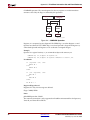
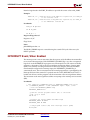
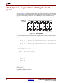
OUTPUT sX, Operand — Write Register sX Value to OUT_PORT,
Set PORT_ID to Operand
The OUTPUT instruction sets the PORT_ID port address to the value specified by either the
register sY or the immediate constant kk. The instruction writes the contents of register sX
to the OUT_PORT output port. FPGA logic captures the output value by decoding the
PORT_ID value and WRITE_STROBE output, as shown in Figure C-7.
FPGA Logic
PicoBlaze Microcontroller
m
Register sX
8
D
OUT_PORT[7:0]
WRITE_STROBE
Register sY or
Literal kk
8
Q
EN
PORT_ID[7:0]
n
UG129_c6_05_052004
Figure C-7:
OUTPUT Operation and FPGA Interface Logic
Examples
OUTPUT sX, sY ; Write register sX to OUT_PORT, set PORT_ID to the
; contents of sY
OUTPUT sX, kk ; Write register sX to OUT_PORT, set PORT_ID to the
; immediate constant kk
PicoBlaze 8-bit Embedded Microcontroller
UG129 (v1.1) June 10, 2004
www.xilinx.com
1-800-255-7778
105
R
Appendix C: PicoBlaze Instruction Set and Event Reference
Pseudocode
PORT_ID Å Operand
OUT_PORT Å sX
PC Å PC + 1
Registers/Flags Altered
Registers: PC
Flags: None
Notes
pBlazIDE Equivalent: OUT
The WRITE_STROBE output is asserted during the second CLK cycle of the two-cycle
OUTPUT operation.
RESET Event
The reset event is not an instruction but the response of the PicoBlaze microcontroller
when the RESET input is High. A RESET Event restarts the PicoBlaze microcontroller and
clears various hardware elements, as shown in Table C-3.
A RESET Event is automatically generated immediately following FPGA configuration,
initiated by the FPGA’s internal Global Set/Reset (GSR) signal. After configuration, the
FPGA application generates RESET Event by asserting the RESET input before a rising
CLK clock edge.
Table C-3:
PicoBlaze Reset Values
Resource
RESET Event Effect
General-purpose Registers
Unaffected.
Program Counter
0
ZERO Flag
0
CARRY Flag
0
INTERRUPT_ENABLE Flag
0
Scratchpad RAM
Unaffected.
Program Store
Unaffected.
CALL/RETURN Stack
Stack Pointer reset.
The general-purpose registers, the scratchpad RAM, and the program store are not affected
by a RESET Event. The CALL/RETURN stack is a circular buffer, although a RESET Event
essentially resets the CALL/RETURN stack pointer.
Pseudocode
if (RESET input = High) then
; clear Program Counter
PC Å 0
; disable the INTERRUPT input by clearing the INTERRUPT_ENABLE flag
INTERRUPT_INPUT Å 0
106
www.xilinx.com
1-800-255-7778
PicoBlaze 8-bit Embedded Microcontroller
UG129 (v1.1) June 10, 2004
R
RETURN [Condition] — Return from Subroutine Call, Possibly with Conditions
; clear the ZERO and CARRY flags
ZERO Å 0
CARRY Å 0
endif
Registers/Flags Altered
Registers: PC, CALL/RETURN stack
Flags: CARRY, ZERO, INTERRUPT_ENABLE
RETURN [Condition] — Return from Subroutine Call, Possibly with
Conditions
The RETURN instruction is the complement to the CALL instruction. The RETURN
instruction is also conditional. The new PC value is formed internally by incrementing the
last value on the program address stack, ensuring that the program executes the
instruction following the CALL instruction that called the subroutine. The RETURN
instruction has no effect on the status of the flags.
The RETURN instruction has both conditional and unconditional variants. A conditional
RETURN is only performed if a test performed against either the ZERO flag or CARRY flag
is true. If unconditional or if the condition is true, the RETURN instruction pops the return
address from the top of the CALL/RETURN stack into the PC. The popped value forces
the program to return to the instruction immediately following the original subroutine
CALL.
Ensure that a RETURN is only performed in response to a previous CALL instruction so
that the CALL/RETURN stack contains a valid address.
The RETURN instruction does not affect the ZERO or CARRY flags. The flag values set prior
to the RETURN instruction are maintained and available after the return from the
subroutine call.
Condition
Depending on the specified condition, the program returns from a subroutine call. If the
specified condition is not met, the program continues on to the next instruction.
Table C-4:
RETURN Instruction Conditions
Condition
<none>
C
NC
Z
NZ
Description
Always true. Return from called subroutine unconditionally.
CARRY = 1. Return from called subroutine if CARRY flag is set.
CARRY = 0. Return from called subroutine if CARRY flag is cleared.
ZERO = 1. Return from called subroutine if ZERO flag is set.
ZERO = 0. Return from called subroutine if ZERO flag is cleared.
Pseudocode
if (Condition = TRUE) then
; pop the top of the CALL/RETURN stack into PC
; TOS = Top of Stack
PC Å TOS + 1; incremented value from Top of Stack
PicoBlaze 8-bit Embedded Microcontroller
UG129 (v1.1) June 10, 2004
www.xilinx.com
1-800-255-7778
107
R
Appendix C: PicoBlaze Instruction Set and Event Reference
else
PC Å PC + 1
endif
Registers/Flags Altered
Registers: PC, CALL/RETURN stack
Flags: Not affected
Notes
Do not use the RETURN instruction to return from an interrupt. Instead, use the RETURNI
instruction.
PBlazIDE Equivalent: RET, RET C, RET NC, RET Z, RET NZ
RETURNI [ENABLE/DISABLE] — Return from Interrupt Service
Routine and Enable or Disable Interrupts
The RETURNI instruction is a special variation of the RETURN instruction. It concludes an
interrupt service routine. The RETURNI instruction is unconditional and pops the return
address from the top of the CALL/RETURN stack into the PC. The return address points
to the instruction preempted by an Interrupt Event. The RETURNI instruction restores the
CARRY and ZERO flags to the values preserved by the Interrupt Event.
The ENABLE or DISABLE operand defines whether the INTERRUPT input is re-enabled
or remains disabled when returning from the interrupt service routine (ISR).
Example
RETURNI ENABLE; Return from interrupt, re-enable interrupts
RETURNI DISABLE; Return from interrupt, leave interrupts disabled
Pseudocode
; pop the top of the CALL/RETURN stack into PC
PC Å TOS
; restore the flags to their pre-interrupt values
CARRY Å PRESERVED_CARRY
ZERO Å PRESERVED_ZERO
; if “ENABLE” specified, re-enable interrupts
if (ENABLE = TRUE) then
INTERRUPT_ENABLE Å 1
else
INTERRUPT_ENABLE Å 0
endif
Registers/Flags Altered
Registers: PC, CALL/RETURN stack
Flags: CARRY, ZERO, INTERRUPT_ENABLE
Notes
Do not use the RETURNI instruction to return from a subroutine CALL. Instead, use the
RETURN instruction.
PBlazIDE Equivalent: RETI ENABLE, RETI DISABLE
108
www.xilinx.com
1-800-255-7778
PicoBlaze 8-bit Embedded Microcontroller
UG129 (v1.1) June 10, 2004
R
RL sX — Rotate Left Register sX
RL sX — Rotate Left Register sX
The rotate left instruction operates on any single data register. Each bit in the specified
register is shifted left by one bit position, as shown in Table C-5. The most-significant bit,
bit 7, shifts both into the CARRY bit and into the least-significant bit, bit 0.
Table C-5:
Rotate Left (RL) Operation
Rotate Left
RL sX
Register sX
CARRY
7
6
5
4
3
2
1
0
Example
RL sX; Rotate left. Bit sX[7] copied into CARRY.
Pseudocode
CARRY Å sX[7]
sX Å { sX[6:0], sX[7]}
if ( sX = 0 ) then
ZERO Å 1
else
ZERO Å 0
endif
PC Å PC + 1
Registers/Flags Altered
Registers: sX, PC
Flags: CARRY, ZERO
RR sX — Rotate Right Register sX
The rotate right instruction operates on any single data register. Each bit in the specified
register is shifted right by one bit position, as shown in Table C-6. The least-significant bit,
bit 0, shifts both into the CARRY bit and into the most-significant bit, bit 7.
Table C-6:
Rotate Right (RR) Operation
Rotate Right
RR sX
Register sX
7
6
5
4
3
2
CARRY
1
0
Example
RR sX; Rotate right. Bit sX[0] copied into CARRY
PicoBlaze 8-bit Embedded Microcontroller
UG129 (v1.1) June 10, 2004
www.xilinx.com
1-800-255-7778
109
R
Appendix C: PicoBlaze Instruction Set and Event Reference
Pseudocode
CARRY Å sX[0]
sX Å {sX[0], sX[7:1]}
if ( sX = 0 ) then
ZERO Å 1
else
ZERO Å 0
endif
PC Å PC + 1
Registers/Flags Altered
Registers: sX, PC
Flags: CARRY, ZERO
SL[ 0 | 1 | X | A ] sX — Shift Left Register sX
There are four variants of the shift left instruction, as shown in Table C-7, that operate on
any single data register. Each bit in the specified register is shifted left by one bit position.
The most-significant bit, bit 7, shifts into the CARRY bit. The last character of the
instruction mnemonic—i.e., ‘0’, ‘1’, ‘X’, or ‘A’—indicates the value shifted into the leastsignificant bit, bit 7.
Table C-7:
Shift Left Operations
Shift Left
Shift Left with ‘0’ fill.
SL0 sX
Register sX
CARRY
7
6
4
3
2
1
0
‘0’
0
‘1’
Shift Left with ‘1’ fill.
SL1 sX
Register sX
CARRY
7
6
5
4
3
2
1
Shift Left, eXtend bit 0.
SLX sX
Register sX
CARRY
7
SLA sX
5
6
5
4
3
2
1
0
Shift Left through All bits, including CARRY.
Register sX
CARRY
7
6
5
4
3
2
1
0
The ZERO flag is always 0 after executing the SL1 instruction because register sX is never
zero.
Examples
SL0 sX; Shift left. 0 shifts into LSB, MSB shifts into CARRY.
110
www.xilinx.com
1-800-255-7778
PicoBlaze 8-bit Embedded Microcontroller
UG129 (v1.1) June 10, 2004
R
SR[ 0 | 1 | X | A ] sX — Shift Right Register sX
SL1 sX; Shift left. 1 shifts into LSB, MSB shifts into CARRY.
SLX sX; Shift left. LSB shifts into LSB, MSB shifts into CARRY.
SLA sX; Shift left. CARRY shifts into LSB, MSB shifts into CARRY.
Pseudocode
case (INSTRUCTION)
when “SL0”
LSB Å 0
when “SL1”
LSB Å 1
when “SLX”
LSB Å sX(7)
when “SLA”
LSB Å CARRY
end case
CARRY Å sX[7]
sX Å {sX[6:0], LSB}
if ( sX = 0 ) then
ZERO Å 1
else
ZERO Å 0
endif
PC Å PC + 1
Registers/Flags Altered
Registers: sX, PC
Flags: CARRY, ZERO
SR[ 0 | 1 | X | A ] sX — Shift Right Register sX
There are four variants of the shift right instruction, as shown in Table C-8, that operate on
any single data register. Each bit in the specified register is shifted right by one bit position.
The least-significant bit, bit 0, shifts into the CARRY bit. The last character of the
instruction mnemonic—i.e., ‘0’, ‘1’, ‘X’, or ‘A’—indicates the value shifted into the mostsignificant bit, bit 7.
Table C-8:
Shift Right Operations
Shift Right
Shift Right with ‘0’ fill.
SR0 sX
Register sX
‘0’
7
6
5
4
3
2
CARRY
1
0
Shift Right with ‘1’ fill.
SR1 sX
Register sX
‘1’
PicoBlaze 8-bit Embedded Microcontroller
UG129 (v1.1) June 10, 2004
www.xilinx.com
1-800-255-7778
7
6
5
4
3
2
CARRY
1
0
111
R
Appendix C: PicoBlaze Instruction Set and Event Reference
Table C-8:
Shift Right Operations (Continued)
Shift Right
Shift Right, sign eXtend.
SRX sX
Register sX
7
6
5
4
3
2
CARRY
1
0
Shift Right through All bits, including CARRY.
SRA sX
Register sX
7
6
5
4
3
2
CARRY
1
0
The ZERO flag is always 0 after executing the SR1 instruction because register sX is never
zero.
Example
SR0
SR1
SRX
SRA
sX;
sX;
sX;
sX;
Shift
Shift
Shift
Shift
right. 0 shifts into MSB, LSB shifts into CARRY.
right. 1 shifts into MSB, LSB shifts into CARRY.
right MSB shifts into MSB, LSB shifts into CARRY.
right CARRY shifts into MSB, LSB shifts into CARRY.
Pseudocode
case (INSTRUCTION)
when “SR0”
MSB Å 0
when “SR1”
MSB Å 1
when “SRX”
MSB Å sX(7)
when “SRA”
MSB Å CARRY
end case
CARRY Å sX[0]
sX Å {MSB, sX[7:1]}
if ( sX = 0 ) then
ZERO Å 1
else
ZERO Å 0
endif
PC Å PC + 1
Registers/Flags Altered
Registers: sX, PC
Flags: CARRY, ZERO
112
www.xilinx.com
1-800-255-7778
PicoBlaze 8-bit Embedded Microcontroller
UG129 (v1.1) June 10, 2004
R
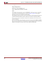
STORE sX, Operand — Write Register sX Value to Scratchpad RAM Location
STORE sX, Operand — Write Register sX Value to Scratchpad RAM
Location
The STORE instruction writes register sX to the scratchpad RAM location specified by
Operand, as shown in Figure C-8. There are 64 scratchpad RAM locations. The two mostsignificant bits of Operand, bits 7 and 6, are discarded and the RAM address is truncated to
the least-significant six bits of Operand, bits 5 to bit 0. Consequently, a STORE operation to
address FF is equivalent to a STORE operation to address 3F.
64-Byte Scratchpad RAM
DATA_IN[7:0]
Register sX
TRUE
Register sY or
Literal kk
DATA_OUT[7:0]
WRITE_ENABLE
[5:0]
ADDRESS[5:0]
[7]
[6]
Figure C-8:
UG129_aC_10_051604
STORE Operation
Examples
STORE sX, (sY) ; Write register sX to scratchpad RAM location
; specified by the contents of register sY
STORE sX, kk
; Write register sX to scratchpad RAM location
; specified by the immediate constant kk
Pseudocode
Scratchpad_RAM[Operand[5:0]] Å sX
PC Å PC + 1
Registers/Flags Altered
Registers: sX, PC
Flags: None
Notes
pBlazIDE Equivalent: The instruction mnemonic, STORE, is the same for both KCPSM3
and pBlazIDE. However, the instruction syntax for indirect addressing is slightly different.
The KCPSM3 syntax places parentheses around the indirect address while the pBlazIDE
syntax uses no parentheses.
KCPSM3 Instruction
PBlazIDE Instruction
STORE sX, (sY)
STORE sX, sY
The STORE instruction is only supported on PicoBlaze microcontrollers for Spartan-3,
Virtex-II, and Virtex-II Pro FPGAs.
PicoBlaze 8-bit Embedded Microcontroller
UG129 (v1.1) June 10, 2004
www.xilinx.com
1-800-255-7778
113
R
Appendix C: PicoBlaze Instruction Set and Event Reference
SUB sX, Operand —Subtract Operand from Register sX
The SUB instruction performs an 8-bit subtraction of two operands, as shown in
Figure C-9. The first operand is any register, which also receives the result of the operation.
The second operand is also any register or an 8-bit constant value. Flags are affected by this
operation. The SUB instruction does not use the CARRY as an input, and therefore there is
no need to condition the flags before use.
The CARRY flag, when set, indicates when an underflow (borrow) occurred.
Register sY or
Literal kk
Borrow
CARRY
Register sX
UG129_aC_03_051604
Figure C-9:
SUB Instruction
Examples
Operand is a register location, sY, or an immediate byte-wide constant, kk.
SUB sX, sY; Subtract register.
SUB sX, kk; Subtract immediate.
sX = sX - sY.
sX = sX - kk.
Description
Operand is subtracted from register sX. The ZERO and CARRY flags are set appropriately.
Pseudocode
sX Å (sX – Operand) mod 256; always an 8-bit result
if ( (sX – Operand) < 0 ) then
CARRY Å 1
else
CARRY Å 0
endif
if ( (sX - Operand) = 0 ) then
ZERO Å 1
else
ZERO Å 0
endif
PC Å PC + 1
Registers/Flags Altered
Registers: sX, PC
Flags: CARRY, ZERO
114
www.xilinx.com
1-800-255-7778
PicoBlaze 8-bit Embedded Microcontroller
UG129 (v1.1) June 10, 2004
R
SUBCY sX, Operand —Subtract Operand from Register sX with Borrow
SUBCY sX, Operand —Subtract Operand from Register sX with
Borrow
The SUBCY instruction performs an 8-bit subtraction of two operands and subtracts an
additional ‘1’ if the CARRY (borrow) flag was set by a previous instruction, as shown in
Figure C-10. The first operand is any register, which also receives the result of the
operation. The second operand is also any register or an 8-bit constant value. Flags are
affected by this operation.
Register sY or
Literal kk
Borrow
CARRY
Borrow In
Register sX
UG129_aC_04_051604
Figure C-10:
SUBCY Instruction
Examples
Operand is a register location, sY, or an immediate byte-wide constant, kk.
SUBCY sX, sY; Subtract register.
SUBCY sX, kk; Subtract immediate.
sX = sX - sY - CARRY
sX = sX - kk - CARRY
Description
Operand and CARRY flag are subtracted from register sX. The ZERO and CARRY flags are
set appropriately.
Pseudocode
if (CARRY = 1) then
sX Å (sX - Operand – 1) mod 256; always an 8-bit result
else
sX Å (sX – Operand) mod 256
; always an 8-bit result
endif
if ( (sX - Operand – CARRY) < 0 ) then
CARRY Å 1
else
CARRY Å 0
endif
if ( ((sX - Operand - CARRY) = 0) or ((sX - Operand - CARRY) = -256) )
then
ZERO Å 1
else
ZERO Å 0
endif
PC Å PC + 1
PicoBlaze 8-bit Embedded Microcontroller
UG129 (v1.1) June 10, 2004
www.xilinx.com
1-800-255-7778
115
R
Appendix C: PicoBlaze Instruction Set and Event Reference
Registers/Flags Altered
Registers: sX
Flags: CARRY, ZERO
Notes
pBlazIDE Equivalent: SUBC
TEST sX, Operand — Test Bit Location in Register sX, Generate
Odd Parity
The TEST instruction performs two related but separate operations. The ZERO flag
indicates the result of a bitwise logical AND operation between register sX and the
specified Operand. The ZERO flag is set if the resulting bitwise AND is zero, as shown in
Figure C-11. The CARRY flag indicates the XOR of the result, as shown in Figure C-12,
which behaves like an odd parity generator.
Register sY
Literal kk
7
6
Register sX
5
7
4
6
3
5
2
4
1
3
0
2
1
0
Bitwise AND
If all bit results are zero,
set ZERO flag.
ZERO
Figure C-11:
Register sY
Literal kk
ZERO Flag Logic for TEST Instruction
7
Register sX
UG129_c3_03_051404
6
7
5
6
4
5
3
4
2
3
1
0
2
1
0
Mask out unwanted bits.
0=mask bit, 1=include bit
Generate odd parity
(XOR) from bit results.
CARRY
Figure C-12:
116
UG129_c3_04_051404
CARRY Flag Logic for TEST Instruction
www.xilinx.com
1-800-255-7778
PicoBlaze 8-bit Embedded Microcontroller
UG129 (v1.1) June 10, 2004
R
TEST sX, Operand — Test Bit Location in Register sX, Generate Odd Parity
Examples
TEST sX, sY ; Test register sX using register sY as the test mask
TEST sX, kk ; Test register sX using the immediate constant kk as the
; test mask
Pseudocode
; logically AND the corresponding bits in sX and the Operand
for (i=0; i<= 7; i=i+1)
{
AND_TEST(i) Å sX(i) AND Operand(i)
}
if (AND_TEST = 0) then
ZERO Å 1
else
ZERO Å 0
end if
; logically XOR the corresponding bits in sX and the Operand
XOR_TEST = 0
for (i=0; i<= 7; i=i+1)
{
XOR_TEST Å AND_TEST(i) XOR XOR_TEST
}
if (XOR_TEST = 1) then; generate odd parity
CARRY Å 1
; odd number of one’s, CARRY=1 for odd parity
else
CARRY Å 0
; even number of one’s, CARRY=0 for odd parity
end if
PC Å PC + 1
Registers/Flags Altered
Registers: PC
Flags: ZERO, CARRY
The TEST instruction is only supported on PicoBlaze microcontrollers for Spartan-3,
Virtex-II, and Virtex-II Pro FPGAs.
PicoBlaze 8-bit Embedded Microcontroller
UG129 (v1.1) June 10, 2004
www.xilinx.com
1-800-255-7778
117
R
Appendix C: PicoBlaze Instruction Set and Event Reference
XOR sX, Operand — Logical Bitwise XOR Register sX with
Operand
The XOR instruction performs a bitwise logical XOR operation between two operands, as
shown in Figure C-13. The first operand is any register, which also receives the result of the
operation. A second operand is also any register or an 8-bit immediate constant. The ZERO
flag is set if the resulting value is zero. The CARRY flag is always cleared by an XOR
instruction.
Register sY
Literal kk
7
Register sX
7
6
6
5
4
5
4
3
3
2
2
1
1
0
0
UG129_aC_08_051604
Figure C-13:
XOR Operation
The XOR operation inverts bits contained in a register, which is used in forming control
signals.
Examples
XOR sX, sY
XOR sX, kk
;
;
;
;
Logically XOR the
the corresponding
Logically XOR the
the corresponding
individual bits of register sX with
bits in register sY
individual bits of register sX with
bits in the immediate constant kk
Pseudocode
; logically XOR the corresponding bits in sX and the Operand
for (i=0; i<= 7; i=i+1)
{
sX(i) Å sX(i) XOR Operand(i)
}
CARRY Å 0
if (sX = 0) then
ZERO Å 1
else
ZERO Å 0
end if
PC Å PC + 1
Registers/Flags Altered
Registers: sX, PC
Flags: ZERO, CARRY is always 0
118
www.xilinx.com
1-800-255-7778
PicoBlaze 8-bit Embedded Microcontroller
UG129 (v1.1) June 10, 2004
R
Appendix D
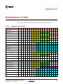
Instruction Codes
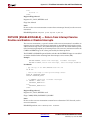
Table D-1 provides the 18-bit instruction code for every PicoBlaze instruction.
Table D-1:
PicoBlaze Instruction Codes
Instruction
17 16 15 14 13 12 11 10
9
8
7
6
5
4
3
2
1
0
ADD sX,kk
0
1
1
0
0
0
x
x
x
x
k
k
k
k
k
k
k
k
ADD sX,sY
0
1
1
0
0
1
x
x
x
x
y
y
y
y
0
0
0
0
ADDCY sX,kk
0
1
1
0
1
0
x
x
x
x
k
k
k
k
k
k
k
k
ADDCY sX,sY
0
1
1
0
1
1
x
x
x
x
y
y
y
y
0
0
0
0
AND sX,kk
0
0
1
0
1
0
x
x
x
x
k
k
k
k
k
k
k
k
AND sX,sY
0
0
1
0
1
1
x
x
x
x
y
y
y
y
0
0
0
0
CALL
1
1
0
0
0
0
0
0
a
a
a
a
a
a
a
a
a
a
CALL C
1
1
0
0
0
1
1
0
a
a
a
a
a
a
a
a
a
a
CALL NC
1
1
0
0
0
1
1
1
a
a
a
a
a
a
a
a
a
a
CALL NZ
1
1
0
0
0
1
0
1
a
a
a
a
a
a
a
a
a
a
CALL Z
1
1
0
0
0
1
0
0
a
a
a
a
a
a
a
a
a
a
COMPARE sX,kk
0
1
0
1
0
0
x
x
x
x
k
k
k
k
k
k
k
k
COMPARE sX,sY
0
1
0
1
0
1
x
x
x
x
y
y
y
y
0
0
0
0
DISABLE INTERRUPT
1
1
1
1
0
0
0
0
0
0
0
0
0
0
0
0
0
0
ENABLE INTERRUPT
1
1
1
1
0
0
0
0
0
0
0
0
0
0
0
0
0
1
FETCH sX, ss
0
0
0
1
1
0
x
x
x
x
0
0
s
s
s
s
s
s
FETCH sX,(sY)
0
0
0
1
1
1
x
x
x
x
y
y
y
y
0
0
0
0
INPUT sX,(sY)
0
0
0
1
0
1
x
x
x
x
y
y
y
y
0
0
0
0
INPUT sX,pp
0
0
0
1
0
0
x
x
x
x
p
p
p
p
p
p
p
p
JUMP
1
1
0
1
0
0
0
0
a
a
a
a
a
a
a
a
a
a
JUMP C
1
1
0
1
0
1
1
0
a
a
a
a
a
a
a
a
a
a
JUMP NC
1
1
0
1
0
1
1
1
a
a
a
a
a
a
a
a
a
a
JUMP NZ
1
1
0
1
0
1
0
1
a
a
a
a
a
a
a
a
a
a
PicoBlaze 8-bit Embedded Microcontroller
UG129 (v1.1) June 10, 2004
www.xilinx.com
1-800-255-7778
119
R
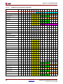
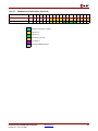
Table D-1:
Appendix D: Instruction Codes
PicoBlaze Instruction Codes (Continued)
Instruction
17 16 15 14 13 12 11 10
9
8
7
6
5
4
3
2
1
0
JUMP Z
1
1
0
1
0
1
0
0
a
a
a
a
a
a
a
a
a
a
LOAD sX,kk
0
0
0
0
0
0
x
x
x
x
k
k
k
k
k
k
k
k
LOAD sX,sY
0
0
0
0
0
1
x
x
x
x
y
y
y
y
0
0
0
0
OR sX,kk
0
0
1
1
0
0
x
x
x
x
k
k
k
k
k
k
k
k
OR sX,sY
0
0
1
1
0
1
x
x
x
x
y
y
y
y
0
0
0
0
OUTPUT sX,(sY)
1
0
1
1
0
1
x
x
x
x
y
y
y
y
0
0
0
0
OUTPUT sX,pp
1
0
1
1
0
0
x
x
x
x
p
p
p
p
p
p
p
p
RETURN
1
0
1
0
1
0
0
0
0
0
0
0
0
0
0
0
0
0
RETURN C
1
0
1
0
1
1
1
0
0
0
0
0
0
0
0
0
0
0
RETURN NC
1
0
1
0
1
1
1
1
0
0
0
0
0
0
0
0
0
0
RETURN NZ
1
0
1
0
1
1
0
1
0
0
0
0
0
0
0
0
0
0
RETURN Z
1
0
1
0
1
1
0
0
0
0
0
0
0
0
0
0
0
0
RETURNI DISABLE
1
1
1
0
0
0
0
0
0
0
0
0
0
0
0
0
0
0
RETURNI ENABLE
1
1
1
0
0
0
0
0
0
0
0
0
0
0
0
0
0
1
RL sX
1
0
0
0
0
0
x
x
x
x
0
0
0
0
0
0
1
0
RR sX
1
0
0
0
0
0
x
x
x
x
0
0
0
0
1
1
0
0
SL0 sX
1
0
0
0
0
0
x
x
x
x
0
0
0
0
0
1
1
0
SL1 sX
1
0
0
0
0
0
x
x
x
x
0
0
0
0
0
1
1
1
SLA sX
1
0
0
0
0
0
x
x
x
x
0
0
0
0
0
0
0
0
SLX sX
1
0
0
0
0
0
x
x
x
x
0
0
0
0
0
1
0
0
SR0 sX
1
0
0
0
0
0
x
x
x
x
0
0
0
0
1
1
1
0
SR1 sX
1
0
0
0
0
0
x
x
x
x
0
0
0
0
1
1
1
1
SRA sX
1
0
0
0
0
0
x
x
x
x
0
0
0
0
1
0
0
0
SRX sX
1
0
0
0
0
0
x
x
x
x
0
0
0
0
1
0
1
0
STORE sX, ss
1
0
1
1
1
0
x
x
x
x
0
0
s
s
s
s
s
s
STORE sX,(sY)
1
0
1
1
1
1
x
x
x
x
y
y
y
y
0
0
0
0
SUB sX,kk
0
1
1
1
0
0
x
x
x
x
k
k
k
k
k
k
k
k
SUB sX,sY
0
1
1
1
0
1
x
x
x
x
y
y
y
y
0
0
0
0
SUBCY sX,kk
0
1
1
1
1
0
x
x
x
x
k
k
k
k
k
k
k
k
SUBCY sX,sY
0
1
1
1
1
1
x
x
x
x
y
y
y
y
0
0
0
0
TEST sX,kk
0
1
0
0
1
0
x
x
x
x
k
k
k
k
k
k
k
k
TEST sX,sY
0
1
0
0
1
1
x
x
x
x
y
y
y
y
0
0
0
0
120
www.xilinx.com
1-800-255-7778
PicoBlaze 8-bit Embedded Microcontroller
UG129 (v1.1) June 10, 2004
R
Table D-1:
PicoBlaze Instruction Codes (Continued)
Instruction
17 16 15 14 13 12 11 10
9
8
7
6
5
4
3
2
1
0
XOR sX,kk
0
0
1
1
1
0
x
x
x
x
k
k
k
k
k
k
k
k
XOR sX,sY
0
0
1
1
1
1
x
x
x
x
y
y
y
y
0
0
0
0
a
Absolute instruction address
x
Register sX
y
Register sY
k
Immediate constant
p
Port address
s
Scratchpad RAM address
PicoBlaze 8-bit Embedded Microcontroller
UG129 (v1.1) June 10, 2004
www.xilinx.com
1-800-255-7778
121