1
floppy
1 sur 16
http://www.walshcomptech.com/ohlandl/floppy/floppy.html
June 1994 Method to Allow the Sharing of I/O Port Addresses between a Floppy Disk Controller and
an IDE Controller within a PS/2 Micro Channel System
April 1994 Conversion Connector for the IBM Personal Computer
Replacing Dried Out Capacitors (to the 8580 Common Devices page)
Comments on 8580 Floppies (to the 8580 Common Devices page)
Installing a Floppy in a 95
Formatting 720K Disk on 1.44MB Floppy
Formatting 360K 3.5" Floppies
System to Floppy Drive List
Floppy Drive to Manufacturer List
95A (82077SL) Floppy Controller
Media formats and transfer rates
Floppy Planar and Drive pinout
2.88 Floppy to Clone Hack Progress
FIFO Mode
2.88MB Floppy
Perpendicular Mode
2.88MB Floppy Disk Construction
Gap2 Information
2.88MB Floppy Source (1,000s of them!!!)
* Marked 2.88MB Floppy Drives
Function of Third Foppy Connector
Error 165- Is The Floppy Working?
8580 Floppy Drives in the 95?
Disable Floppy Under Setup
OS/2 MCA Foppy ADDs
OS/2 ver 3 and DMF Workaround
Planar Floppy Pinout
34 pin Floppy Header Pinouts
Removable Media Security
Secure Media Mode
2.88MB Electronic Eject Floppy
EE Floppy Security Circuitry
Registers
EE Commands (Registers- Lock, Unlock, Eject)
Issue an Enhanced Command
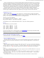
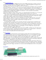
The floppy controller and interface connector reside on the system board.
95A Floppy Controller
It is an NEC N82077SL, 68 pin SOIC. It seems Intel bought the chip rights from NEC.
The diskette drive controller supports:
o Four data transfer rates: - 250k / 300k / 500k / 1M bits per second
o Programmable precompensation
o A 16-byte FIFO buffer
o PS/2 Style 3.5' 1.44/2.88MB, enhanced 2.88MB, 5.25" 1.2MB
o The secure media mode and the enhanced commands
Snippets In particular, the 82077SL internally samples the IDENT and MFM pin level which is used to
18/01/2015 10:07
floppy
2 sur 16
http://www.walshcomptech.com/ohlandl/floppy/floppy.html
configure the operating mode (PC-AT, Model 30, PS/2) on the falling edge of h/w reset.
82077AA Removal of DMA Request(DRQ) During an Under/Overrun Condition
82077 SL Power-on Reset Problem
82077SL: t23a TIMING CLARIFICATION
Interface Between 82077AA/SL and the Floppy Drive
5. Sony MP-F40W - 14/15 There are dash 14 and 15 are two new drives from Sony that handle 4 MB
requirements. The MP-F40W-14 has the DENSITY SELECT 1, DENSITY SELECT 0 on pins 2 and 33
respectively, whereas the MP-F40W-15 has the DENSITY SELECT 1, DENSITY SELECT 0 on pins 2
and 6 respectively. As it is obvious from the table below, daisy chaining is easily done if the 82077AA/SL
is connected in the PS/2 mode (by typing IDENT high) with either type of drive, the only difference
being the location of DENSITY SELECT 0.
Replacing The 82077SL With The 82078 (44PIN)
Replacing The 82077SL WITH 82078 (64PIN)
95 and 90 Floppy Controller
These systems use the Intel 82077AA floppy controller. The EE floppy drive can be used on them, but
the AA does not support the EE functions.
9577 Bermuda Floppy Controller
These systems use either the 82077AA, 82077SL (rare), or the NS PC8477AV floppy controller.
Usually, systems with the NS controller use "*" marked floppy drives. BUT I have found some
82077AA/* combinations, plus what I believe to be a late Bermuda with a 82077SL floppy controller
with a * marked floppy on it...
From David Beem
Here is the listing of 82077xx FDC chips that are able to support the 2.88 EHD drives:
FDC Location:
35SX Planar #1
35SX Planar #2
53 486SLC2 Planar
56SLC Planar
57 486SLC2 Planar
77 (Bemuda) Planar #1
77 (Bemuda) Planar #2
77 (Lacuna) Planar
Reply 80 Planar
85 (X, K, N) Planar
95 (K-M) Planar
95 (N-Q) Planar
Processor:
Intel 386SX-20
Intel 386SX-20
IBM 486SLC2-50
IBM 386SLC-20
IBM 486SLC2-50
Upgrade Intel 486DX2-66
Upgrade Cyrix 486DX2-75
Upgrade 83MHz POD
Upgrade 83MHz POD
i486SX-33, DX2-66
Type 1-Type 3 complex
Type 4 Complex
FDC
82077AA
82077AA
82077SL-1
82077AA
82077SL
NS8477-AV
82077AA
82077SL
82077SL
82077SL (1)
82077AA (2)
82077SL (3)
1 Ed. All models support the 3.5" Electronic Eject floppy drive. (and 2.88!!)
2 Ed. Known to support 2.88 Note: early 8595s do not support the 2.88MB floppy
3 Ed. All N-Q support the EE floppy (and 2.88!!)
One pattern seems to emerge from the PS/2 planars: the "souped-up" or second-gen planars have the
82077SL FDC chips. A couple of surprises though. I did find two other FDC chips on my equipment. The
first on Bermuda planar #1 is a National Semiconductor 8477AV-2 chip *without* the "(C) NEC 1979",
but with "(C) NSC 1991". Probably a 82077AA replacement that is reverse enginered enough to avoid
having to use the NEC copyright. That system is unchanged from the way I bought it, with an "*" 2.88
drive. The spare 2.88 I got on eBay I am unsure of the original model is a non-"*" drive.
There is a smaller surface mount Intel 82091AA in my HP NetServer that does bear the "(C) NEC'79"
& also "(C) Intel '86 '93". Just a guess again about being a replacement for the 82077AA with the end of
the part number. All the Intel 82077AA and 82077SL chips I have otherwise have "(C) NEC 1979" &
"(C) Intel '86 '91" of course. Other clone motherboards and adapter cards I have don't look like they have
18/01/2015 10:07
floppy
3 sur 16
http://www.walshcomptech.com/ohlandl/floppy/floppy.html
a stand-alone FDC chip. Most support the EHD drives in the BIOS, so it has to be a variant of the
82077xx somehow (Even the enhanced NEC 72065B doesn't support 2.88 drives.).
FDC chips are supposed to give which level they are by a "ver" command given to the chip. By my
reference all flavors of the 82077 return the same value. I have tried a routine for the FDC ver command
that so far has *not* worked. The PS/2 35SX and 53 486SLC2 planars both give a return value for a
standard FDC that doesn't support 2.88 drives, then make the computer unable
to read the drive! Here is the (of all things, BASIC) routine anyway & I am going to keep trying to get it
to work.
OLDVAL = INP(&H3F5)
OUT &H3F5, &H10
FDCVER = INP(&H3F5)
FDC = ""
IF FDCVER = &H80 THEN FDC = "NEC 765 / Intel 8272 or compatible FDC, no 2.88 support"
IF FDCVER = &H81 THEN FDC = "Intel 82077xx or compatible FDC, 2.88 support"
IF FDCVER = &H90 THEN FDC = "NEC 72065B or compatible FDC, no 2.88 support"
IF FDC = "" THEN FDC = "Unknown FDC returning value " + HEX$(FDCVER) + "h"
PRINT FDC
OUT &H3F5, OLDVAL
Formatting 720K Disks on a 1.44MB Floppy
>Why don't you use format /f:720 in the DOS window to make the 1.44 disks 720k suitable? Maybe the
720k machine can't read them later, but this depends on the
drive. 720k drives write wider tracks than 1.44 do.
Peter blearily looks up from his bowl of Fruit Loops 'n Beer and sez:
Guess I jump in here and clear some misunderstandments.
1. Older PS/2 are non-media sensing - means: whether the floppy has the right-hand "media type hole"
or not doesn't bother these machines.
2. "Klone Chop-Suey-PCs" use to have FDDs that *do* test for the media type
hole - and consequently refuse to read from a down-formatted 1.44MB floppy. You
*need* to use a piece of transparency tape around the front edge and cover the
hole from the *underside*. This does not have any effect on the older PS/2s as
explained in 1. above. The "generic" FDDs use a set of switches on the right
side to test for a) floppy presence and b) presence of a "High Density" hole.
(2.88MB drives have a third switch that tests for "eXtra Density" hole, which
sits a bit further away from the lower edge of the floppy). Some older PS/2
FDDs have the switches too - but they are used for media presence only - not
for detecting the media type, like e.g. in a Mod. 50/60, 55/65, 70/80 and the
30-286.
3. If you'd closed the media type hole on am actually 1.44MB formatted floppy
and try to format it on a "non PS/2" machine it might complain on a false
format in a first attempt. You better use a PS/2 (see 1. )
On DOS after 3.x you need to use FORMAT A: /U /F:720 to format to 720KB.
On DOS 3.x you need to use FORMAT A: /N:9 /T:80 to force a 720KB format.
The /U parameter in later DOS (and Win95 DOS box) does an "unconditional"
format and ignores all data and formats on the floppy. It does a *physical*
format across all sectors and actually writes the 720K structures at all.
If you would use the /Q parameter the drive would only try to rewrite the first
sectors with the File Allocation Table (FAT) on that floppy and leave the rest
untouched - that will not work and will result in a media error anyway.
The /N:9 parameter on older DOS is the difference between 720K and 1.44MB format. Both use 80
tracks (the /T:80 parameter), but 1.44 uses 18 sectors (would be /N:18), while 720K uses half of them -
18/01/2015 10:07
floppy
4 sur 16
http://www.walshcomptech.com/ohlandl/floppy/floppy.html
therefore /N:9.
The *track width* is the same on 720 and 1.44 format - because both use 80 tracks and the stepper
motor does the same step-width - and the R/W-head gap does not change during the process ... :-)
Once you'd formatted a 1.44MB floppy to 720KB you might be unable to re-format
the floppy back to 720KB - even if you remove the covering tape from the media
type hole. 1.44MB floppies use a Ferro-Chrome (FeCr) base material, which
"holds" the magnetism a bit stronger than the Ferrite-Oxyd (FeO) material
usually used for 720K floppies. The R/W amplifier on generic FDDs might be
unable to fully erase the 720K format in this case.
Formatting 3.5" to 360KB
Once again, Peter slips up by saying:
Old PS/2 that do not care (much) for the floppy formats and use an older DOS (like Mod. 50/60, 55/65,
70/80 with DOS 3.3 to 5.0) can be convinced to format a 3.5" floppy to 360KB with using FORMAT A:
/N:9 /T:40 .... if you then have a machine with a 5.25" drive as well (as on my good old trusty Mod.
80-A21) you can use DISKCOPY B: A: to make 3.5" copies from the 5.25" disks onto 3.5".
Interestingly, most machines support 3.5" / 360KB format and can at least read it.
System to Floppy Drive List
This list does not mean that you cannot use a later drive on an older system. That is determined by the
BIOS of the system. I do not know the limits of all these models.
EE = Electronic Eject
7568 Floppy Drive
1.44MB 15F7503 (Damn 32 pin tape connector!)
8535/8540 Floppy Drives
1.44 85F0050
2.88 64F4148
2.88 92F0132 (EE) Do these have 82077SL?
8550 Floppy Drives
1.44 64F0207
8555SX Floppy Drives
1.44 64F0162
8556/8557 Floppy Drives
1.44 85F0050
2.88 64F4148
2.88 92F0132
8560, 8565, 8580 Floppy Drives
1.44 64F0162 (Pin Conn. LED below slot)
1.44 72X8523 (Edge Conn. LED above slot)
8570 Floppy Drives
1.44 64F0207
8570/8573 (P70/P75) Floppy Drives
1.44 38F5936
1.44 64F0162 (Not listed, but will also fit, and is electrically compatible.)
8590 Floppy Drives
1.44 64F0162
2.88 64F0204
2.88 64F4148 Not listed, but useable. See Warning below!
2.88 92F0132 (EE) Not listed. Does not have a 82077SL Floppy Ctrl.
8595/9585/9595/9595A Floppy Drives
1.44 64F0162
2.88 64F0204
18/01/2015 10:07
floppy
5 sur 16
http://www.walshcomptech.com/ohlandl/floppy/floppy.html
2.88 64F4148 Not listed, but useable. See Warning below!
9556/9576 and 9557/9577 and i/s
1.44 85F0050
2.88 64F4148
2.88 92F0132 (EE) Bermuda 56/57 planars lack 82077SL. Does not support EE.
Server 500
2.88 82G1888
Floppy FRU to Manufacturer List
List is NOT complete. Remember that an FRU can refer to many similar drives.
1.2MB Floppy FRU to Manufacturer List
64F4102 (Electronic Eject)
Canon MD5501A
1.44MB Floppy FRU vs. Manufacturer
64F0162 (Pin Conn. LED below slot)
Mitsubishi MF355C-599MQ4
ALPS DFP723D30B
15F7503
ALPS DFP723D12F (32 pin tape connector!)
2.88MB FRU vs. Manufacturer
64F0204
Mitsubishi MF365C-799MA
64F4148
Mitsubishi MF356C-799MS
Mitsubishi MF356F-899MF Asterix Marked!
54G1679
ALPS B12HP004113 Possibly Japanese models only (Thanks, Sandy!)
82F1888
Mitsubishi MF356F-815MB (Uses clone-like short floppy eject button)
2.88 92F0132 (Electronic Eject)
Sony MP-F40W-07 (also marked MFD-40W-05)
64F0206 vs. 64F4148
From Peter
These have no grey plastic sled undersides but the metal mounting plate with integrated side rails. I
think that's the major difference between 64F0206 (Peter, don't you mean 64F0204?) and 64F4148 .. if
you look into EPRM you will find that all -4148s are for 35/40, 56/57 and 76/77 - while the -0206 is for
the Mod. 85/90/95.
Mounting Hardware
Model 85/90/95 Floppy Drive Slide
64F0156
33F5613
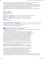
Mechanics of 2.88 vs 1.44
This was derived from Intel 82077SL for Super Dense Floppies . The artwork is from this intel
document, I just cleaned them up a bit.
PERPENDICULAR RECORDING MODE
Toshiba has taken the 2 MB floppy and doubled the storage capacity by doubling the number of bits per
track. Toshiba achieved this by an innovative magnetic recording mode, called the vertical or the
18/01/2015 10:07
floppy
6 sur 16
http://www.walshcomptech.com/ohlandl/floppy/floppy.html
perpendicular recording mode. This mode utilizes magnetization perpendicular to the recording medium
plane. This is in contrast to the current mode of longitudinal recording which uses the magnetization
parallel to the recording plane. By making the bits stand vertical as opposed to on their side, recording
density is effectively doubled, Figure 1. The new perpendicular mode of recording not only produces
sharp magnetization transitions necessary at higher recording densities, but is also more stable.
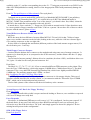
2.88MB Floppy Construction
The 4 MB disks utilize barium ferrite coated substrates to achieve perpendicular mode of
magnetization. Current disks use cobalt iron oxide (Co-g-Fe 2 O 3 ) coating for longitudinal recording.
The barium ferrite ensures good head to medium contact, stable output and durability in terms of long
use. High coercivity is required to attain high recording density for a longitudinal recording medium
(coercivity specification of a disk refers to the magnetic field strength required to make an accurate
record on the disk). A conventional head could not be used in this case; however, the barium ferrite disk
has low coercivity and the conventional ferrite head can be used. The new combination heads include a
pre-erase mechanism, i.e., the ferrite ring heads containing erase elements followed by the read/write
head. These erase elements have deep overwrite penetration and ensure complete erasure for writing new
data. The distance between the erase elements and the read/write head is about 200mm. This distance is
important from the floppy disk controller point of view and will be discussed in later sections.
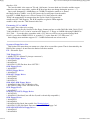
Gap2 Differences
The implementation of 4 MB drives requires understanding the Gap2 (see Figures 2a and 2b) and VCO
timing requirements unique to these drives. These new requirements are dictated by the design of the
``combination head'' in these drives. Rewriting of disks in the 4 MB drives requires a pre-erase gap to
erase the magnetic flux on the disk preceding the writing by the read/write gap. The read/write gap in the
4 MB drive does not have sufficient penetration (as shown in Figure 4a) to overwrite the existing data.
18/01/2015 10:07
floppy
7 sur 16
http://www.walshcomptech.com/ohlandl/floppy/floppy.html
In the conventional drives, the read/write gap had sufficient depth and could effectively overwrite the
older data as depicted in Figure 4b. It must be noted that it is necessary to write the conventional 2 MB
media in the 4 MB drive at 500 Kbps perpendicular mode. This ensures proper erasure of existing data
and reliable write of the new data. The pre-erase gap in the 4 MB floppy drives is activated only during
format and write commands. Both the pre erase gap and read/write gap are activated at the same time.
As shown in Figure 4a, the pre-erase gap precedes the read/write gap by 200mm. This distance
translated to bytes is about 38 bytes at a data rate of 1 Mbps and 19 bytes at 500 Kbps. Whenever the
read/write gap is enabled by the Write Gate signal the pre-erase gap is activated at the same time.
2.88MB Floppy source
There is a outfit called WSG Group (site is under heavy construction) that is a high volume diskette
supplier. They currently have over 600,000 finished, ready to go diskettes, 2DD; 2HD; and 2ED., with a
back-up of raw materials of over 2 Million diskettes awaiting production...
They have in-stock the following:
New--Duplicator Grade ED 3.5 diskettes... 60,000 +
Recycled--ED Diskettes---3M, Maxell, Fuji brands........80,000 +..
All of diskettes are pre-certified and formatted 100%. They offer a lifetime guaranteee..
Prices:
The ED Diskettes are priced as follows:
10pk
25pk
50pk
50pk
w/labels
w/labels
w/labels
bulk bag
IBM/Fmt
IBM/Fmt
IBM/Fmt
IBM/Fmt
$ 7.00
$12.00
$ 22.00
$ 20.00
To order from single pack to volume quantities, email John Schattin The listed prices DO NOT include
shipping. But how heavy is a box of floppies anyways?
Resistor Network by 95A Floppy Controller
Bourns 4816P-002 -103 (bussed 10k ohm) Spec sheet HERE.
* Marked 2.88MB Floppy Drives
I just noticed that the 2.88 floppy drive in one of my PS/2 machines has an asterisk (*) printed on the
top side of the blue eject button. Anybody has a clue as to what that might indicate? Is it just there for
looks?
From Peter
The drives with the asterisk are those for 35/40, 56/57 and 76/77 - but *not* for 85/90/95. Should be a
64F4148, while the "others" use a 64F0204. They differ slightly in the pinout and can damage the planar
on earlier Mod. 90 / 95. (Ed. I'm using an asterisk 2.88 on my 9590. Note that this is a later planar!)
Hi Al !
>9595 floppy is FRU 64F0204. Floppy I have that is mounted to the sled is FRU 64F4148. Can I use this
floppy on my 9595/8595 without fear?
That 64F4148 is the 35/40, 56/57, 76/77 FDD. If you really like your 95 you *do not* try it in there. A
team mate once did it ... and it took us some days to solder in a new FDD-controller ... (main problem
was to find one at first)
I cannot figure out *exactly* what caused the mess, but it has to do with the "security features"
18/01/2015 10:07
floppy
8 sur 16
http://www.walshcomptech.com/ohlandl/floppy/floppy.html
available on the 95 - and the corresponding pins on the 56 - 77 being not present and set to GND. For the
older 8595 IBM published a warning, that use of the inappropriate FDD could permanently damage the
sysboard.
From Us, The god-Emperor of Microchannel (The royal plural)
I whipped out my asterix marked FRU 64F4148. It's a Mitsubishi MF356F-899MF. I just pulled my
stock 2.88 from my Bermuda planar 9577- it is a 64F4148 as well, BUT the Mitsubishi model is
MF356C-799MF. First postulation of the "Law of the Asterix" (you heard it here first, folks!) is that the
MF356F is the model that is incompatible with early 90s/95s.
As noted above, I have used the " * " floppy on a 9590 with no unusual results. I figure that there must
be a more primitive floppy controller used on the 35/40 etc. systems. I do not have one of these to check.
Anyone with the answer, please tell me!
Visual Differences Between M356C and M356F
From Peter
BTW: the most obvious difference between Mitsu MF356C-799 and -899 is that -799 has a longer
upper cover and the connector on the left side (looking at the rear), while the -899 has a shorter upper
cover and the connector on the rear right side.
So they differ a lot through the mechanism (different position of the head actuator stepper motor). For
the electronics part - I can't say.
Third Floppy Connector Purpose
> I noticed that the diskette drive connects to the motherboard using some sort of strange connector. It
appears to be about 44 pins or so (compared to the SCSI connector), and the ribbon cable has *3* plugs
coming off it.
I never heard of anyone putting 3 diskette drives in a machine (let alone a PS/2), and diskette drives use
30 (?) pins. So what are the extra pins and connector for?
From Peter
The Mod. 56 / 57 / 76 / 77 / 85 / 90 / 95 use a somewhat different FDD-connector on the planar. They
have the Type-3 FDD-interface, which also supports 2.88MB drives ("Media-Sense Drives"). The third
connector is for a very odd ITBU Internal Tape Backup Unit, which was a slightly modified IRWIN
120MB tape. The machine supports only 2 FDDs - as usual.
Ed. Configuring The 82077 For Tape Drive Mode
The FDD-plugs are 34-pins (2 x 17), only the planar connector is a bit strange 44-pins. This type of
interface contains also lines for security control, i.e. in connection with the "Electronic Eject 2.88MB
FDD", which can be locked and password protected.
Tried to find a pinout of the connector but haven't found any at the moment ...
System Reports 165- But Is the Floppy Working?
From Tim Clarke
>b) the floppy controller/drive/cable is suspect and needs looking at. However, one would have expected
a 601 error is things were really bad.
Peter RespondsNot always. A disfuntional FDD may as well cause a 165. "It is configured - but does not respond". If
the heads stuck, do not pass Track-00 tests or have RDATA stuck high or such you will surely get a
600-series error. But if the drive has a "DC leak" and simply appears as absent it is judged as "device
missing but still present in the configuration".
8580 34 Pin Floppy Drives
From Fred Spencer
18/01/2015 10:07
floppy
9 sur 16
http://www.walshcomptech.com/ohlandl/floppy/floppy.html
These pin style diskette drives can be sub-divided into two sub-groups. The original model 8580 drives
are identified by the P/N 90X6766. I have seen these drives labeled as manufactured by Mitsubishi, Alps
Electric and YE Data. Later models were produced for the 8595 and they are identified by the P/N
72X6112 or 1619618 and also sometimes accompanied by the FRU # 64F0162 , which is also the FRU #
reported in the HMM (October 1994) for both the 8580 and the 8595. HOWEVER, I have discovered
that although the 8595 drives (FRU #64F0162) will work on the 8580, the 8580 drives (P/N 90X6766)
will NOT work on the 8595!! The drives with FRU # 64F0162 have also been labeled as manufactured
by Mitsubishi, Alps Electric and YE Data.
Disabling Floppy under Setup
Even if you use the selectable boot and remove the 1.44, A: drive from the boot sequence, there is a
"safety" device that always looks at the A: drive for a Reference Diskette. If there is a Reference
Diskette in the drive it will override "selectable boot"
OS/2 Floppy Devices
After the installation of OS/2 Warp and OS/2 Warp Fullpack, CONFIG.SYS file contains two diskettedriver statements: IBM1FLPY.ADD and IBM2FLPY.ADD. Only one of the drivers is loaded; the other
just takes up disk space. On MCA machines, you need IBM2FLPY.ADD. You may delete
IBM1FLPY.ADD
NOTES: HERE
* IBM1FLPY.ADD with /MCA works on the IBM PS/2 Micro Channel systems.
* If installation is from DMF diskettes, use IBM1FLPY.ADD /MCA for PS/2 MCA systems.
OS/2 Warp with WIN-OS/2 V300
Microsoft has confirmed they have changed thier compression utility for windows products now
shipping. The type of compression is not recognized by OS/2 3.X on some older PS/2's. For example,
some model 80, 70 and 65 machines.A programming error was found but will not be corrected. It is a
permanent restriction..
Local Fix
1. In config.sys
rem basedev=ibm2flpy.add
and use
basedev=ibm1flpy.add /mca
2. If above does not work then use following instead,
BASEDEV=IBM1FLPY.ADD /MCA /A:0 /U:0 /F:1.44MB /CL:AT
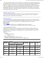
Media formats supported
MEDIA
SIZE
CAPACITY
UNFORMATTED
SECTORS
PER TRACK
NO. OF
TRACKS
FORMATTED
DATA
RATE
(KBPS)
3.5 in
1.0MB
720KB
9
80
250
3.5 in
2.0MB
1.44MB
18
80
500
3.5 in
4.0MB
2.88MB
36
80
1000
5.25 in
0.5MB
360KB
9
40
300/250
5.25 in
1.6MB
1.20MB
15
80
500
18/01/2015 10:07
floppy
10 sur 16
http://www.walshcomptech.com/ohlandl/floppy/floppy.html
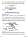
Floppy Cable Pinout
The diskette drive cable converts a 2- by 22-pin connector on the system board into three 2- by 17-pin
connectors for attaching internal diskette drives. The cables pass control and data signals between the
diskette drive controller on the system board and the drives. They also provide the power to each drive.
Note The 3.5-inch drives are required to support media-sensing.
Floppy Planar Pinouts
System board 44 pin connector pinout (95A and Lacuna Planars)
Pin
Signal
Pin
Signal
1
-2nd drive installed
23
Ground
2
Data rate select 1
24
-Write enable
3
+5 V dc
25
Ground
Drive type ID 1/Drive status 1 26
-Track0
4
5
Ground
27 Media type 0/Drive status 2
6
+12 V dc
28
-Write protect
7
Ground
29
Ground
8
-Index
30
-Read data
9
Drive Type 0/Drive status 0
31
Ground
10
Reserved
32
-Head 1 select
11
Ground
33
Data rate select 0
12
-Drive select 0
34
Diskette change
13
Ground
35
Drive select 1
14
-Security command 0
36
Ground
15
Ground
37
-Security command 1
16
-Motor enable 0
38
Ground
17
Media type 1/Drive status 3
39
-Motor enable1
18
-Direction in
40
-Drive select 2
19
Ground
41
Ground
20
-Step
42
-Security command 2
21
Ground
43
Ground
22
-Write data
44
-Motor enable 2
34-Pin Header Interface
34-Pin Header (Non-media sense)
Pin
Pin
Signal
Pin
34-Pin Header (Media Sense)
Signal
Pin
Signal
18/01/2015 10:07
floppy
11 sur 16
http://www.walshcomptech.com/ohlandl/floppy/floppy.html
Signal
1
Ground
2
-HD select
1
Ground
2
Data rate select
3
+5v DC
4
Drive Type
ID 1
3
+5v DC
4
Drive type ID 1/ Drive
Status1
5
Ground
6
+12v DC
5
Ground
6
+12v DC
7
Ground
8
-Index
7
Ground
8
9
Ground
10
Reserved
9
Drive type ID 0
10
11
Ground
12
-Drive select
11
Ground
12 -Drive select
13
Ground
14
Reserved
13
Ground
14
-Security Command
15
Ground
16
-Motor enable
15
Ground
16
-Motor enable
17
Ground
18
-Direction in
17
Media type 1/ Drive
status 3
18
-Directionin
19
Ground
20
-Step
19
Ground
20 -Step
21
Ground
22
-Write data
21
Ground
22
-Write data
23
Ground
24
Write enable
23
Ground
24
-Write enable
25
Ground
26
-Track 0
25
Ground
26
-Track 0
27
Ground
28
-Write protect
27
Media type ID 0/ Drive
status 2
28
-Write protect
29
Ground
30
-Read data
29
Ground
30
-Read data
31
Ground
32 -Head 1 Select 31
Ground
32
-Head 1 select
33
Ground
34
-Diskette
change
Data rate select
34
-Diskette change
33
-Index
Reserved
2.88 Floppy to Clone Hack
Just when you thought it couldn't be done... This is not a 100% reliable way to hack the 2.88, BUT it
shows that a strong possibility exists.
From Sören Hedlund
Since Febr I`ve tested with Sony MP-F40W-03 - and still working on these machines, so I dont beleive
there is a reliability problem. Yes, 1.44 disk works fine, but not 720 - you loose about 5% when
formatting. However, I also had to make a circuit to make these Sony MP-F40W-03 to work properly
with all three formats.
Tested MB with IBM 2.88:
Tyan S1572 ATX - SMC fdc37c669qf p
Aopen AX5T
- SMC fdc37c932apm
QDI TITANIUM 1 - NS9724ax pc87336vlj
Asus PVI-486SP3 - UMC um8669f
Epox MVP3G5
- Winbond W83877TF
(Hot Shuttle Hot-433 - UMC um8663af -- No 2.88 !)
(Compaq PRESARIO - not in bios - No 2.88 !)
So if BIOS support 2.88 it does not mean it will work, the I/O - chip must support it as well.
18/01/2015 10:07
floppy
12 sur 16
http://www.walshcomptech.com/ohlandl/floppy/floppy.html
From Joseph Realmuto Jr
The first is a 386-40 with a SIDE4 HP multi-IO card(2.88MB capable floppy controller). Since this
machine does not have built-in 2.88MB support I had to use a TSR which updates the computer's bios.
The floppy controller on the card is capable of 1 Mb/sec data rate. I
connected pins 34, 32, 30, 28, 26, 24, 22, 20, 18, 16, 12, 8, and 2 on the P/S2 floppy to the corresponding
pins on the controller. I left pins 4, 6, 10, and 14 on the floppy unconnected. Pin 3 of the floppy was
connected to +5V and pin 11 to ground. The floppy is a Sony MP-F40W-03 connected as the B drive(the
A drive is a standard 1.44 MB). The floppy reads, writes, and formats 2.88MB media. I can also format
1.44MB media to 2.88MB without drilling an extra hole in it. In fact, all media is automatically
formatted at the drive's native capacity
unless forced with the /F switch. I was not able to get a Mitsubishi MF356F-899MF drive to work on this
machine (pins 26 and 34 seemed to oscillate, and the computer said there was a seek error).
The second is a Packard Bell Pentium machine with an Intel Triton chipset and an on- board 2.88MB
capable floppy controller. I used the above Mitsubishi floppy(again as the B drive) and this time simply
used an edge card adaptor which connects only the top (even-numbered) pins,
and pin 1(ground). I added +5V on pin 3 by soldering a wire from one of the hard drive power plugs.
Again, this floppy works just as well as the one on the 386 machine. It also seems to automatically
format at its native capacity regardless of which meda is actually in the drive
unless forced with the /F switch.
It seems that pins 4, 10, and 14 can be left either connected or unconnected(I recommend leaving
unconnected). Pin 6 should be either connected to pin 6 on the controller (which is an N/C on clone
controllers) or left unconnected. It should never be connected to +12V even though this is in the pinout
for the P/S2 floppy for two reasons: 1)+12V is not used at all by the floppy drive 2)On some (Sony
MP-F40W-15) pin 6 is DENSITY SELECT 0 and putting +12V on a 5V logic line can fry the drive,
controller, and possibly even the motherboard.
As a last note, the 1.44MB media seems to work well at 2.88MB. It formats error-free and seems to
hold data with no problem. I am doing some long-term testing to see if it will retain data. At this time I
do not recommend putting anything important on these media. Please e-mail
me if you know of anybody who has tested this long term.
From David Beem
As I am building up from the basics I am not having too much trouble so far. Having learned not to
assume on my or anyone's theories I am slowly gaining information to see if I can pull this off. I pulled
out my Model 35SX, disconnected the 1.44M & connected the spare (non-"*") 2.88 drive. After the
expected 16x error I have it configure itself & I am up and running with a 2.88Mb A: drive on a
386SX-20 computer. Cool. Even like the guy said on your page that he was able to format a standard HD
disk as EHD with no complaints. Mine differed in that I had to tell it with the /F:2.88 switch, otherwise it
formatted it as 1.44Mb (that was expected, but not *assumed* on my part).
I am using some pretty cheap bulk floppies too. I don't know how long the information will last, but it
is good to know I can test the EHD media without having to find the exact diskette out there. The Model
35SX uses a 82077 controller as well. As luck would have it I also have an ISA Adaptec 1542 SCSI board
with an onboard 82077 floppy controller too. I can cross-check the IBM planars to it too see the pinout
changes.
Sony Board
With the 1.44Mb PS/2 floppy drives IBM moved one ground and one unused pin to put the 5 &
18/01/2015 10:07
floppy
13 sur 16
http://www.walshcomptech.com/ohlandl/floppy/floppy.html
12VDC power on the 34-pin connector. By my references they seem to have inverted a half-dozen
control signals too, but left them in the same relative position on the connector. Modifying the Sony
board with 3 circuit trace cuts and 3 jumpers to account for the power connections at least allows the
clone to power up. The Motor Enable signal (one of the ones on the "twist" of the cable) is not inverted,
so it spins the drive up when a read from the floppy is given. The stepper moter doesn't move though
because that is one of the inverted signals.
I am going to see which buffer chip is used to invert the signals between the Adaptec board and the
IBM planars. There is probably a riser with the correct buffer chip(s) I can assemble to do the task with a
little work. At least at the drive end the connector is pretty much the same. What I have seen is that at
the IBM planar end the Model 35, 40, & 53 have a 40-pin connector and the Model 56, 57, 76, & 77
have a 44-pin connector. I will figure out the pinouts for those too.
FIFO Mode
The diskette drive controller uses a FIFO buffer to enhance DMA transfer operations. The FIFO buffer
is used in the data transfer phase only, and its operation is transparent to programs.
Removable Media Security
The diskette drive controller in this system supports the optional 2.88MB enhanced diskette drive,
which has a media-security feature. This diskette drive supports Lock, Unlock, and Eject commands; the
Lock command inhibits diskettes from being removed or inserted. Additionally, if the privileged-access
password is set and the diskette drive is in the boot path, the drive is automatically locked.
FRUs I have seen for the 2.88MB enhanced diskette drive 92F0132, 92F0129, and I saw 82G1888
mentioned as well.
Secure Media Mode
The secure media mode allows the diskette drive to receive enhanced commands. These commands
provide a means of controlling access to the media in the diskette drives. Through these commands,
programs can eject a diskette or disable the mechanism, which inhibits media from being removed or
inserted.
To determine whether the mode and commands are supported for a specific drive:
1. With the enhanced-command bit set to 1, test the state of the drive type (1,0) signals by reading the
Drive Status register.
Note For info on enhanced-command bit, refer to System Control Port C (Hex 007C).
2. With the enhanced-command bit set to 0, retest the state of the signals. If the signals change to a
binary 11, the mode and commands are supported for that drive.
2.88MB Electronic Eject Floppy
0 Eject with eject button or sofware
1 Eject via software ONLY
An optional 2.88 MB diskette drive with security features is available on some IBM PC Server systems.
The diskette drive is a 3.5-inch, one-inch high drive with media sense capability for the standard diskette
18/01/2015 10:07
floppy
14 sur 16
http://www.walshcomptech.com/ohlandl/floppy/floppy.html
capacities of 720 KB, 1.44 MB, and 2.88 MB. It can read and write data up to a formatted capacity of
2.88 MB, while maintaining read and write capability with 720 KB and 1.44 MB diskette drives.
A control signal has been added to the diskette interface that supports LOCK, UNLOCK, and EJECT
commands issued by the operating system. If the privileged-access password is not set, the diskette is
unlocked during POST. If the password is set, the boot process does not unlock the diskette drive unless
it is the designated IPL source. an operating system utility. For SCSI devices, there is a proposed
standard UNLOCK command. In this case, the operating system will control the LOCK command if the
privileged-access password is set. Access to the unlocking function with specific user authorization can
be controlled by secured system software.
In the event of power loss, the system retains its state (secured or unsecured) independent of the state
of the battery. A diskette can be inserted in the drive, but it cannot be removed if the power is off.
When the drive is turned on and locked, the media cannot be inserted or removed.
Enhanced 2.88MB Floppy Security Circuitry
>1. Do all floppy controller chips have the ability to pulse the leading edge of the of the security cmd
signal?
No. Only the later machines support the security functions. It has been offered for the 9595 and 9585
at least. The EE 2.88MB drive comes in two "flavours": 92F0129 for all 9585 and 9595A, 92F0132 for
35/40, 56/57 (all), 76/77 (all)
For the later group I can tell, that the 35/40 and 8556/8557 have no security features integrated, most
likely the 9556/9557 and "Bermuda" 9576/9577 lack the feature too. The FDD interface on these
machines is a bit different from those on the "Servers". However: the Server 77i had these security
features mentioned in early flyers. So it appears as if the "Lacuna" machines *have* the appropriate
additional controller logic. (Ed. The 82077SL FD controller has the extra circuitry that supports EE)
>2. Is this a hardware function of the controller?
Yes. But requires BIOS support.
>3. Can this be controlled by software (thru BIOS) on any controller?
There was a tool I cannot recall the name from, which could "lock" the EE-FDD function. You could
neither insert a Floppy when it is empty, nor pull one out if there is one in the drive. I think they use a
logic gate programmed on the controller to stop the motorized eject / load function.
Tim Clarke
Hi Louis,
I think what the announcement (and Peter et al.) talked about was software to *cause* the floppy to
eject *not* prevent/disable the feature, although I won't swear to this. I would think the physical switch is
your only option for that. I have the 'electronic eject' 5.25" slimline floppy in one of my 95s and none of
the PC-DOS 7 DRVLOCK /on, DRVLOCK /off or EJECT utilities accept it (B:) as a supported drive.
And, having thought about it ***there ain't no signal lines to control this on the floppy interface***. So,
perhaps you should get a microswitch and patch that into the circuit, then mount the microswitch
somewhere devious. Or, even sneakier, figure out if any of the drive select 2/3 or motor enable 2/3
signals are actually passed through the ribbon but not connected on the floppy drive's PCB circuitry and
use one as 'gating control' signal for the eject signal.
>The *electronic* eject drive is like the standard push button drive. SONY made both of them. The EE
drive allows you to lock the floppy disk in the drive by flipping the eject button disable switch on the side
of the drive. Unfortantly the program to software eject the disk via the OS is missing in action ...
The DISKETTE.DGS diagnostics "overlay" tests the "security features" of the electronic diskette
drives when possible. A bit of reverse engineering might reveal what is needed for recreation of these
utilities. However, doesn't PC-DOS v7/2000 have the DRVLOCK and EJECT commands? More fodder
for the dedicated hacker.
Peter
It has - but it fails with the EE-FDD as far as I can tell. At least when using it in a Lacuna. As far as I
can tell they have been intended for CD-ROMs and MODs. DRVLOCK de-activates the eject button and
18/01/2015 10:07
floppy
15 sur 16
http://www.walshcomptech.com/ohlandl/floppy/floppy.html
EJECT forces a media ject on them. *That* is known to work under PC-DOS 7.0 with a CD-ROM
installed ... I use EJECT recently on my last PC-DOS survivor.
From Ernst Fueloep
With OS/2 you can use the security features for the enhanced 2.88 diskette drive from the diskette icon
in the drives folder. Just press the right mouse button and you will get options for "Lock disk", "Eject
disk" and "Unlock disk".
Make sure the security switch on the diskette drive is set to 1. You can find this switch on the right
side of the drive.
Electronic Eject Commands
Lock Drive Disables the load-and-eject mechanism. The drive will not eject a loaded diskette, nor will
it load a diskette. (Depending on the characteristics of the drive, it may load the diskette and immediately
try to eject it).
Note Allow 500 mS after an Eject Media command before issuing Lock Drive cmd.
Unlock Drive Enables the load-and-eject mechanism, which allows diskettes to be removed from and
inserted into the selected drive.
Eject Media Same as pressing the eject button on the front of the drive; it causes the drive to eject a
diskette. This command is ignored if the drive is locked.
To issue an enhanced command:
Set the value in the data-rate-select bits (in the Data Rate Control register) at the positive-going edge of
the -security cmd signal.
1. Select the drive and save the state of the data-rate-select bits.
2. Ensure that the System Control Port C is available (bit 7 will be 0).
3. Set the enhanced-command bit to 0 (bit 0 of the System Control Port C).
4. Set the data-rate-select bits to the desired command.
5. Set the enhanced-command bit to 1.
6. Restore the data-rate-select bits to the desired data rate.
NoteIf the drive is deselected before the enhanced-command bit is reset to 1, the drive does not perform
the command.
Command encoding of data rate select (1,0) signals.
Enhanced Commands
DATA RATE SELECT 1 0 RESULTING COMMAND
00
Eject Media
01
Lock Drive
10
Unlock Drive
11
Reserved
Diskette Drive Registers
REGISTER
R/W ADDRESS
Status register A R
03F0
18/01/2015 10:07
floppy
16 sur 16
http://www.walshcomptech.com/ohlandl/floppy/floppy.html
Status register
R
03F1
Digital output
R/W 03F2
Drive status
R
03F3
Controller status R
03F4
Precomp select
W
03F4
Command/data
R/W 03F5
Digital input
R
03F7
Data rate control W
03F7
9595 Main Page
18/01/2015 10:07