1
HDevelop User's Guide
HDevelop, the interactive development environment of HALCON, Version 11.0
All rights reserved. No part of this publication may be reproduced, stored in a retrieval system, or
transmitted in any form or by any means, electronic, mechanical, photocopying, recording, or otherwise,
without prior written permission of the publisher.
Edition
Edition
Edition
Edition
Edition
Edition
Edition
Edition
Edition
Edition
Edition
Edition
Edition
Edition
Edition
Edition
Edition
Edition
Edition
Edition
Edition
1
2
3
4
5
6
6a
7
7a
8
8a
8b
9
9a
9b
10
10a
11
11a
11b
12
July 1997
November 1997
March 1998
April 1999
October 2000
June 2002
December 2002
December 2003
July 2004
July 2005
April 2006
December 2006
June 2007
October 2007
April 2008
December 2008
June 2009
October 2010
April 2011
November 2011
May 2012
Copyright © 1997-2012
(HALCON 5.1)
(HALCON 5.2)
(HALCON 6.0)
(HALCON 6.1)
(HALCON 6.1.1)
(HALCON 7.0)
(HALCON 7.0.1)
(HALCON 7.1)
(HALCON 7.1.1)
(HALCON 7.1.2)
(HALCON 8.0)
(HALCON 8.0.1)
(HALCON 8.0.2)
(HALCON 9.0)
(HALCON 9.0.1)
(HALCON 10.0)
(HALCON 10.0.1)
(HALCON 10.0.2)
(HALCON 11.0)
by MVTec Software GmbH, München, Germany
MVTec Software GmbH
Protected by the following patents: US 7,062,093, US 7,239,929, US 7,751,625, US 7,953,290, US
7,953,291. Further patents pending.
Microsoft, Windows, Windows XP, Windows Server 2003, Windows Vista, Windows Server 2008, Windows 7, Microsoft .NET, Visual C++, Visual Basic, and ActiveX are either trademarks or registered
trademarks of Microsoft Corporation.
Silicon Graphics, SGI, IRIX, and OpenGL are either trademarks or registered trademarks of Silicon
Graphics, Inc.
Mac OS X and OpenCL are trademarks of Apple Inc.
All other nationally and internationally recognized trademarks and tradenames are hereby recognized.
More information about HALCON can be found at: http://www.halcon.com/
About This Manual
This manual is a guide to HDevelop, the interactive development environment for the HALCON machine
vision library.
This manual is intended for users who want to use HDevelop as a convenient gateway to the HALCON
library or who want to deploy and test machine vision applications with it. It is not an introduction to
the HALCON machine vision library. A working knowledge of the concepts of HALCON is assumed.
Please refer to the Quick Guide to become acquainted with HALCON. In-depth knowledge of image
processing is not required to start working with HDevelop.
The manual is divided into the following chapters:
• Introducing HDevelop
This chapter explains the basic concepts of HDevelop.
• Getting Started
This chapter explains how to start HDevelop. It provides a quick overview of the graphical user
interface, and shows you how to run the supplied example programs.
• Acquiring Images with HDevelop
This chapter explains the fundamental part of machine vision applications – how to acquire images.
• Programming HDevelop
This chapter explains how to develop applications in HDevelop.
• HDevelop Procedures
This chapter introduces the concepts of breaking a large program into small maintainable and
reusable units.
• Graphical User Interface
This chapter explains the graphical user interface of HDevelop and how to interact with it.
• HDevelop Assistants
This chapter describes how to use the machine vision assistants of HDevelop.
• HDevelop Language
This chapter explains the syntax and semantics of the language used in HDevelop expressions.
• Code Export
This chapter explains the export of a HDevelop program to C, C++, Visual Basic, Visual Basic
.NET, or C#.
• Miscellaneous
This chapter describes keycodes, warning and error windows, and provides miscellaneous information.
Contents
1
Introducing HDevelop
1.1 Facts about HDevelop . . . . . . . . . . . . . . . . . . . . . . . . . . . . . . . . . . . .
1.2 HDevelop XL . . . . . . . . . . . . . . . . . . . . . . . . . . . . . . . . . . . . . . . .
1.3 Terminology & Usage . . . . . . . . . . . . . . . . . . . . . . . . . . . . . . . . . . . .
11
12
12
12
2
Getting Started
2.1 Running HDevelop . . . . . . . . . . . . . . . . . . . . . . . . . . . . . . . . . . . . .
2.2 Running Example Programs . . . . . . . . . . . . . . . . . . . . . . . . . . . . . . . .
15
15
18
3
Acquiring Images with HDevelop
3.1 Reading Images From Files . . . . . . . . . . . . . . . . . . . .
3.2 Viewing Images . . . . . . . . . . . . . . . . . . . . . . . . . .
3.3 Image Acquisition Assistant . . . . . . . . . . . . . . . . . . .
3.3.1 Acquiring Images From Files or Directories . . . . . . .
3.3.2 Acquiring Images Through Image Acquisition Interfaces
3.3.3 Modifying the Generated Code . . . . . . . . . . . . . .
.
.
.
.
.
.
.
.
.
.
.
.
.
.
.
.
.
.
.
.
.
.
.
.
.
.
.
.
.
.
.
.
.
.
.
.
.
.
.
.
.
.
.
.
.
.
.
.
.
.
.
.
.
.
.
.
.
.
.
.
.
.
.
.
.
.
.
.
.
.
.
.
.
.
.
.
.
.
23
23
24
25
26
28
32
Programming HDevelop
4.1 Start a New Program . . . . . . . . . . . . . . . .
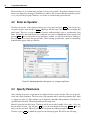
4.2 Enter an Operator . . . . . . . . . . . . . . . . . .
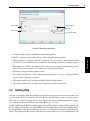
4.3 Specify Parameters . . . . . . . . . . . . . . . . .
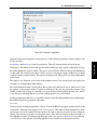
4.4 Getting Help . . . . . . . . . . . . . . . . . . . . .
4.5 Add Additional Program Lines . . . . . . . . . . .
4.6 Understanding the Image Display . . . . . . . . .
4.7 Inspecting Variables . . . . . . . . . . . . . . . . .
4.8 Improving the Threshold Using the Gray Histogram
4.9 Edit Lines . . . . . . . . . . . . . . . . . . . . . .
4.10 Re-Execute the Program . . . . . . . . . . . . . .
4.11 Save the Program . . . . . . . . . . . . . . . . . .
4.12 Selecting Regions Based on Features . . . . . . . .
4.13 Looping Over the Results . . . . . . . . . . . . . .
4.14 Summary . . . . . . . . . . . . . . . . . . . . . .
.
.
.
.
.
.
.
.
.
.
.
.
.
.
.
.
.
.
.
.
.
.
.
.
.
.
.
.
.
.
.
.
.
.
.
.
.
.
.
.
.
.
.
.
.
.
.
.
.
.
.
.
.
.
.
.
.
.
.
.
.
.
.
.
.
.
.
.
.
.
.
.
.
.
.
.
.
.
.
.
.
.
.
.
.
.
.
.
.
.
.
.
.
.
.
.
.
.
.
.
.
.
.
.
.
.
.
.
.
.
.
.
.
.
.
.
.
.
.
.
.
.
.
.
.
.
.
.
.
.
.
.
.
.
.
.
.
.
.
.
.
.
.
.
.
.
.
.
.
.
.
.
.
.
.
.
.
.
.
.
.
.
.
.
.
.
.
.
.
.
.
.
.
.
.
.
.
.
.
.
.
.
33
33
34
34
35
36
38
38
39
41
41
41
41
43
44
HDevelop Procedures
5.1 Procedure Types . . . . . . . . . . . . . . . . . . . . . . . . . . . . . . . . . . . . . . .
5.2 File Types . . . . . . . . . . . . . . . . . . . . . . . . . . . . . . . . . . . . . . . . . .
45
45
46
4
5
.
.
.
.
.
.
.
.
.
.
.
.
.
.
.
.
.
.
.
.
.
.
.
.
.
.
.
.
.
.
.
.
.
.
.
.
.
.
.
.
.
.
.
.
.
.
.
.
.
.
.
.
.
.
.
.
.
.
.
.
.
.
.
.
.
.
.
.
.
.
.
.
.
.
.
.
.
.
.
.
.
.
.
.
.
.
.
.
.
.
.
.
.
.
.
.
.
.
.
.
.
.
.
.
.
.
.
.
.
.
.
.
.
.
.
.
.
.
.
.
.
.
.
.
.
.
.
.
.
.
.
.
.
.
.
.
.
.
.
.
.
.
.
.
.
.
.
.
.
.
.
.
.
.
.
.
.
.
.
.
.
.
.
.
.
.
.
.
.
.
.
.
.
.
.
.
.
.
.
.
.
.
.
.
.
.
.
.
.
.
.
.
.
.
.
.
.
.
.
.
.
.
.
.
.
.
.
.
.
.
.
.
.
.
.
.
.
.
.
.
.
.
.
.
.
.
46
46
47
47
47
48
49
50
6 Graphical User Interface
6.1 Main Window . . . . . . . . . . . . . . . . . . . . . . . . .
6.2 Menu . . . . . . . . . . . . . . . . . . . . . . . . . . . . .
6.2.1 Menu File . . . . . . . . . . . . . . . . . . . . . .
6.2.2 Menu Edit . . . . . . . . . . . . . . . . . . . . . .
6.2.3 Menu Execute . . . . . . . . . . . . . . . . . . . .
6.2.4 Menu Visualization . . . . . . . . . . . . . . . .
6.2.5 Menu Procedures . . . . . . . . . . . . . . . . . .
6.2.6 Menu Operators . . . . . . . . . . . . . . . . . .
6.2.7 Menu Suggestions . . . . . . . . . . . . . . . . .
6.2.8 Menu Assistants . . . . . . . . . . . . . . . . . .
6.2.9 Menu Window . . . . . . . . . . . . . . . . . . . . .
6.2.10 Menu Help . . . . . . . . . . . . . . . . . . . . . .
6.3 Tool Bar . . . . . . . . . . . . . . . . . . . . . . . . . . . .
6.4 Program Window . . . . . . . . . . . . . . . . . . . . . . .
6.4.1 Program Window Actions . . . . . . . . . . . . . .
6.4.2 Editing Programs . . . . . . . . . . . . . . . . . . .
6.4.3 Program Counter, Insert Cursor, and Breakpoints . .
6.4.4 Context Menu . . . . . . . . . . . . . . . . . . . . .
6.4.5 Creating Procedures . . . . . . . . . . . . . . . . .
6.4.6 Editing Procedures . . . . . . . . . . . . . . . . . .
6.4.7 Side Effects of Procedure Changes . . . . . . . . . .
6.4.8 Providing Procedure Documentation . . . . . . . . .
6.4.9 Protecting a Procedure . . . . . . . . . . . . . . . .
6.4.10 Profiler . . . . . . . . . . . . . . . . . . . . . . . .
6.5 Operator Window . . . . . . . . . . . . . . . . . . . . . . .
6.5.1 Operator Name Field . . . . . . . . . . . . . . . . .
6.5.2 Parameter Display . . . . . . . . . . . . . . . . . .
6.5.3 Control Buttons . . . . . . . . . . . . . . . . . . . .
6.6 Variable Window . . . . . . . . . . . . . . . . . . . . . . .
6.6.1 Iconic Variables . . . . . . . . . . . . . . . . . . . .
6.6.2 Control Variables . . . . . . . . . . . . . . . . . . .
6.7 Graphics Window . . . . . . . . . . . . . . . . . . . . . . .
6.7.1 Interactive Creation and Handling of ROIs and XLDs
6.8 Help Window . . . . . . . . . . . . . . . . . . . . . . . . .
6.9 Zoom Window . . . . . . . . . . . . . . . . . . . . . . . .
6.10 Gray Histogram Window . . . . . . . . . . . . . . . . . . .
6.10.1 Interactive Visual Operations . . . . . . . . . . . . .
.
.
.
.
.
.
.
.
.
.
.
.
.
.
.
.
.
.
.
.
.
.
.
.
.
.
.
.
.
.
.
.
.
.
.
.
.
.
.
.
.
.
.
.
.
.
.
.
.
.
.
.
.
.
.
.
.
.
.
.
.
.
.
.
.
.
.
.
.
.
.
.
.
.
.
.
.
.
.
.
.
.
.
.
.
.
.
.
.
.
.
.
.
.
.
.
.
.
.
.
.
.
.
.
.
.
.
.
.
.
.
.
.
.
.
.
.
.
.
.
.
.
.
.
.
.
.
.
.
.
.
.
.
.
.
.
.
.
.
.
.
.
.
.
.
.
.
.
.
.
.
.
.
.
.
.
.
.
.
.
.
.
.
.
.
.
.
.
.
.
.
.
.
.
.
.
.
.
.
.
.
.
.
.
.
.
.
.
.
.
.
.
.
.
.
.
.
.
.
.
.
.
.
.
.
.
.
.
.
.
.
.
.
.
.
.
.
.
.
.
.
.
.
.
.
.
.
.
.
.
.
.
.
.
.
.
.
.
.
.
.
.
.
.
.
.
.
.
.
.
.
.
.
.
.
.
.
.
.
.
.
.
.
.
.
.
.
.
.
.
.
.
.
.
.
.
.
.
.
.
.
.
.
.
.
.
.
.
.
.
.
.
.
.
.
.
.
.
.
.
.
.
.
.
.
.
.
.
.
.
.
.
.
.
.
.
.
.
.
.
.
.
.
.
.
.
.
.
.
.
.
.
.
.
.
.
.
.
.
.
.
.
.
.
.
.
.
.
.
.
.
.
.
.
.
.
.
.
.
.
.
.
.
.
.
.
.
.
.
.
.
.
.
.
.
.
.
.
.
.
.
.
.
.
.
.
.
.
.
.
.
.
.
.
.
.
.
.
.
.
.
.
.
.
.
.
.
.
.
.
.
.
.
.
.
.
.
.
.
.
.
.
.
.
.
.
.
.
.
.
.
.
.
.
.
.
.
.
.
.
.
.
.
.
.
.
.
.
.
.
.
.
.
.
.
.
.
.
.
.
.
.
.
.
.
.
.
.
.
.
.
.
.
.
.
.
.
.
.
.
.
.
.
.
.
.
.
.
.
.
.
.
.
.
.
.
.
.
.
.
.
.
.
.
.
.
.
.
.
.
.
.
.
.
.
.
.
.
.
.
.
.
.
.
.
.
.
.
.
.
.
.
.
.
.
.
.
.
.
.
.
.
.
.
.
.
.
.
.
.
.
.
.
.
.
51
51
54
54
66
97
105
118
121
127
128
128
134
136
138
139
140
146
147
150
155
157
158
162
164
167
167
168
170
171
173
176
182
187
192
197
199
202
5.3
5.4
5.5
5.6
5.7
5.2.1 HDevelop Programs
5.2.2 External Procedures
5.2.3 Libraries . . . . . .
Procedure Scope . . . . . .
Procedure Locations . . . .
Procedure Resolution . . . .
Protected Procedures . . . .
Procedure Documentation .
.
.
.
.
.
.
.
.
.
.
.
.
.
.
.
.
.
.
.
.
.
.
.
.
.
.
.
.
.
.
.
.
.
.
.
.
.
.
.
.
.
.
.
.
.
.
.
.
.
.
.
.
.
.
.
.
.
.
.
.
.
.
.
.
.
.
.
.
.
.
.
.
.
.
.
.
.
.
.
.
.
.
.
.
.
.
.
.
.
.
.
.
.
.
.
.
.
.
.
.
.
.
.
.
.
.
.
.
.
.
.
.
.
.
.
.
.
.
.
.
.
.
.
.
.
.
.
.
7
6.11 Feature Histogram Window . . . . . . . . . . . . . . . . . . . . .
6.12 Feature Inspection Window . . . . . . . . . . . . . . . . . . . . .
6.13 Line Profile Window . . . . . . . . . . . . . . . . . . . . . . . .
6.13.1 ROI Menu of the Line Profile Window . . . . . . . . . . .
6.13.2 Line Profile Display . . . . . . . . . . . . . . . . . . . .
6.13.3 Input . . . . . . . . . . . . . . . . . . . . . . . . . . . .
6.13.4 Line Profile Options . . . . . . . . . . . . . . . . . . . .
6.13.5 Output . . . . . . . . . . . . . . . . . . . . . . . . . . .
6.13.6 Statistics . . . . . . . . . . . . . . . . . . . . . . . . . .
6.13.7 Focusing Your Camera: How to Test Images for Sharpness
6.14 OCR Training File Browser . . . . . . . . . . . . . . . . . . . . .
6.14.1 Windows of the Training File Browser . . . . . . . . . . .
6.14.2 Steps for working with the OCR Training File Browser . .
6.14.3 Actions within the Training File Browser . . . . . . . . .
6.15 Dialogs . . . . . . . . . . . . . . . . . . . . . . . . . . . . . . .
6.15.1 File Selection Dialog . . . . . . . . . . . . . . . . . . . .
6.15.2 Unsaved Changes . . . . . . . . . . . . . . . . . . . . . .
.
.
.
.
.
.
.
.
.
.
.
.
.
.
.
.
.
.
.
.
.
.
.
.
.
.
.
.
.
.
.
.
.
.
.
.
.
.
.
.
.
.
.
.
.
.
.
.
.
.
.
.
.
.
.
.
.
.
.
.
.
.
.
.
.
.
.
.
.
.
.
.
.
.
.
.
.
.
.
.
.
.
.
.
.
.
.
.
.
.
.
.
.
.
.
.
.
.
.
.
.
.
.
.
.
.
.
.
.
.
.
.
.
.
.
.
.
.
.
.
.
.
.
.
.
.
.
.
.
.
.
.
.
.
.
.
.
.
.
.
.
.
.
.
.
.
.
.
.
.
.
.
.
.
.
.
.
.
.
.
.
.
.
.
.
.
.
.
.
.
.
.
.
.
.
.
.
.
.
.
.
.
.
.
.
.
.
.
.
.
.
.
.
.
.
.
.
.
.
.
.
.
.
.
206
208
210
211
211
212
212
212
213
214
215
215
217
217
221
221
222
HDevelop Assistants
7.1 Image Acquisition Assistant . . . . . . . . . . . . . . . .
7.1.1 Tab Source . . . . . . . . . . . . . . . . . . . . .
7.1.2 Tab Connection . . . . . . . . . . . . . . . . . .
7.1.3 Tab Parameters . . . . . . . . . . . . . . . . . .
7.1.4 Tab Inspect . . . . . . . . . . . . . . . . . . . .
7.1.5 Tab Code Generation . . . . . . . . . . . . . .
7.1.6 Menu Bar . . . . . . . . . . . . . . . . . . . . . .
7.2 Calibration Assistant . . . . . . . . . . . . . . . . . . . .
7.2.1 Introducing the Calibration Assistant of HDevelop
7.2.2 How to Calibrate with the Calibration Assistant . .
7.2.3 Results of the Calibration . . . . . . . . . . . . .
7.2.4 Generating Code . . . . . . . . . . . . . . . . . .
7.2.5 Calibration Assistant Reference . . . . . . . . . .
7.3 Matching Assistant . . . . . . . . . . . . . . . . . . . . .
7.3.1 Introducing the Matching Assistant of HDevelop .
7.3.2 How to Use the Matching Assistant of HDevelop .
7.3.3 Matching Assistant Reference . . . . . . . . . . .
7.4 Measure Assistant . . . . . . . . . . . . . . . . . . . . . .
7.4.1 Introducing the Measure Assistant of HDevelop . .
7.4.2 How to Use the Measure Assistant of HDevelop . .
7.4.3 Results . . . . . . . . . . . . . . . . . . . . . . .
7.4.4 Code Generation . . . . . . . . . . . . . . . . . .
7.4.5 Advanced Measuring Tasks . . . . . . . . . . . .
7.4.6 Measure Assistant Reference . . . . . . . . . . . .
7.5 OCR Assistant . . . . . . . . . . . . . . . . . . . . . . .
7.5.1 Introducing the OCR Assistant of HDevelop . . .
7.5.2 Setup . . . . . . . . . . . . . . . . . . . . . . . .
7.5.3 Segmentation . . . . . . . . . . . . . . . . . . . .
.
.
.
.
.
.
.
.
.
.
.
.
.
.
.
.
.
.
.
.
.
.
.
.
.
.
.
.
.
.
.
.
.
.
.
.
.
.
.
.
.
.
.
.
.
.
.
.
.
.
.
.
.
.
.
.
.
.
.
.
.
.
.
.
.
.
.
.
.
.
.
.
.
.
.
.
.
.
.
.
.
.
.
.
.
.
.
.
.
.
.
.
.
.
.
.
.
.
.
.
.
.
.
.
.
.
.
.
.
.
.
.
.
.
.
.
.
.
.
.
.
.
.
.
.
.
.
.
.
.
.
.
.
.
.
.
.
.
.
.
.
.
.
.
.
.
.
.
.
.
.
.
.
.
.
.
.
.
.
.
.
.
.
.
.
.
.
.
.
.
.
.
.
.
.
.
.
.
.
.
.
.
.
.
.
.
.
.
.
.
.
.
.
.
.
.
.
.
.
.
.
.
.
.
.
.
.
.
.
.
.
.
.
.
.
.
.
.
.
.
.
.
.
.
.
.
.
.
.
.
.
.
.
.
.
.
.
.
.
.
.
.
.
.
.
.
.
.
.
.
.
.
.
.
.
.
.
.
.
.
.
.
.
.
.
.
.
.
.
.
.
.
.
.
.
.
.
.
.
.
.
.
.
.
.
.
.
.
.
.
.
.
.
.
.
.
.
.
.
.
.
.
.
.
.
.
.
.
.
.
.
.
.
.
.
.
.
.
.
.
.
.
.
.
.
.
.
.
.
.
.
.
.
.
.
.
223
225
225
226
227
228
229
230
230
230
233
244
245
248
252
252
254
261
293
293
294
298
300
301
306
312
312
314
316
.
.
.
.
.
.
.
.
.
.
.
.
.
.
.
.
.
.
.
.
.
.
.
.
.
.
.
.
.
.
.
.
.
.
.
.
.
.
.
.
.
.
.
.
.
.
.
.
.
.
.
.
.
.
.
.
.
.
.
.
.
.
.
.
.
.
.
.
.
.
.
.
.
.
.
.
.
.
.
.
.
.
.
.
.
.
.
.
.
.
.
.
.
.
.
.
.
.
.
.
.
.
.
.
.
.
.
.
.
.
.
.
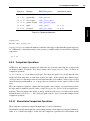
7.5.4
7.5.5
7.5.6
7.5.7
OCR Classifier . . . . . .
Results . . . . . . . . . .
Code Generation . . . . .
OCR Assistant Reference
.
.
.
.
.
.
.
.
.
.
.
.
.
.
.
.
.
.
.
.
.
.
.
.
.
.
.
.
.
.
.
.
.
.
.
.
.
.
.
.
.
.
.
.
.
.
.
.
.
.
.
.
.
.
.
.
.
.
.
.
.
.
.
.
.
.
.
.
.
.
.
.
.
.
.
.
.
.
.
.
.
.
.
.
.
.
.
.
.
.
.
.
.
.
.
.
.
.
.
.
.
.
.
.
.
.
.
.
.
.
.
.
.
.
.
.
320
326
328
329
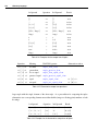
8 HDevelop Language
8.1 Basic Types of Parameters . . . . . . . . . . . . . .
8.2 Control Types and Constants . . . . . . . . . . . . .
8.3 Variables . . . . . . . . . . . . . . . . . . . . . . .
8.3.1 Scope of Variables (local or global) . . . . .
8.4 Operations on Iconic Objects . . . . . . . . . . . . .
8.5 Expressions for Input Control Parameters . . . . . .
8.5.1 General Features of Tuple Operations . . . .
8.5.2 Assignment . . . . . . . . . . . . . . . . . .
8.5.3 Basic Tuple Operations . . . . . . . . . . . .
8.5.4 Tuple Creation . . . . . . . . . . . . . . . .
8.5.5 Type Operations . . . . . . . . . . . . . . .
8.5.6 Basic Arithmetic Operations . . . . . . . . .
8.5.7 Bit Operations . . . . . . . . . . . . . . . .
8.5.8 String Operations . . . . . . . . . . . . . . .
8.5.9 Comparison Operations . . . . . . . . . . .
8.5.10 Elementwise Comparison Operations . . . .
8.5.11 Boolean Operations . . . . . . . . . . . . . .
8.5.12 Trigonometric Functions . . . . . . . . . . .
8.5.13 Exponential Functions . . . . . . . . . . . .
8.5.14 Numerical Functions . . . . . . . . . . . . .
8.5.15 Miscellaneous Functions . . . . . . . . . . .
8.5.16 Operation Precedence . . . . . . . . . . . .
8.6 Reserved Words . . . . . . . . . . . . . . . . . . . .
8.7 Control Flow Operators . . . . . . . . . . . . . . . .
8.8 Error Handling . . . . . . . . . . . . . . . . . . . .
8.8.1 Tracking the Return Value of Operator Calls .
8.8.2 Exception Handling . . . . . . . . . . . . .
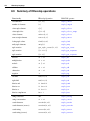
8.9 Summary of HDevelop operations . . . . . . . . . .
8.10 HDevelop Error Codes . . . . . . . . . . . . . . . .
.
.
.
.
.
.
.
.
.
.
.
.
.
.
.
.
.
.
.
.
.
.
.
.
.
.
.
.
.
.
.
.
.
.
.
.
.
.
.
.
.
.
.
.
.
.
.
.
.
.
.
.
.
.
.
.
.
.
.
.
.
.
.
.
.
.
.
.
.
.
.
.
.
.
.
.
.
.
.
.
.
.
.
.
.
.
.
.
.
.
.
.
.
.
.
.
.
.
.
.
.
.
.
.
.
.
.
.
.
.
.
.
.
.
.
.
.
.
.
.
.
.
.
.
.
.
.
.
.
.
.
.
.
.
.
.
.
.
.
.
.
.
.
.
.
.
.
.
.
.
.
.
.
.
.
.
.
.
.
.
.
.
.
.
.
.
.
.
.
.
.
.
.
.
.
.
.
.
.
.
.
.
.
.
.
.
.
.
.
.
.
.
.
.
.
.
.
.
.
.
.
.
.
.
.
.
.
.
.
.
.
.
.
.
.
.
.
.
.
.
.
.
.
.
.
.
.
.
.
.
.
.
.
.
.
.
.
.
.
.
.
.
.
.
.
.
.
.
.
.
.
.
.
.
.
.
.
.
.
.
.
.
.
.
.
.
.
.
.
.
.
.
.
.
.
.
.
.
.
.
.
.
.
.
.
.
.
.
.
.
.
.
.
.
.
.
.
.
.
.
.
.
.
.
.
.
.
.
.
.
.
.
.
.
.
.
.
.
.
.
.
.
.
.
.
.
.
.
.
.
.
.
.
.
.
.
.
.
.
.
.
.
.
.
.
.
.
.
.
.
.
.
.
.
.
.
.
.
.
.
.
.
.
.
.
.
.
.
.
.
.
.
.
.
.
.
.
.
.
.
.
.
.
.
.
.
.
.
.
.
.
.
.
.
.
.
.
.
.
.
.
.
.
.
.
.
.
.
.
.
.
.
.
.
.
.
.
.
.
.
.
.
.
.
.
.
.
.
.
.
.
.
.
.
.
.
.
.
.
.
.
.
.
.
.
.
.
.
.
.
.
.
.
.
.
.
.
.
.
.
.
.
.
.
.
.
.
.
.
.
.
.
.
.
.
.
.
.
.
.
.
.
.
.
.
.
.
.
.
.
.
.
.
.
.
.
.
.
.
.
.
.
.
.
.
.
.
.
.
.
.
.
.
.
.
.
.
.
.
.
.
.
.
.
.
.
.
.
.
.
.
.
.
.
.
.
.
.
.
.
.
.
.
.
.
.
.
.
.
.
.
337
337
338
341
341
342
343
343
345
347
348
350
350
351
352
357
357
359
359
360
360
362
363
363
363
369
370
370
372
376
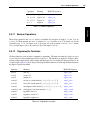
9 Code Export
9.1 Code Generation for C++ . . . . . . . . . . . . . . . . . .
9.1.1 Basic Steps . . . . . . . . . . . . . . . . . . . . .
9.1.2 Optimization . . . . . . . . . . . . . . . . . . . .
9.1.3 Used Classes . . . . . . . . . . . . . . . . . . . .
9.1.4 Limitations and Troubleshooting . . . . . . . . . .
9.2 Code Generation for C# (HALCON/.NET) . . . . . . . . .
9.2.1 Basic Steps . . . . . . . . . . . . . . . . . . . . .
9.2.2 Program Structure . . . . . . . . . . . . . . . . .
9.2.3 Limitations and Troubleshooting . . . . . . . . . .
9.3 Code Generation for Visual Basic .NET (HALCON/.NET)
.
.
.
.
.
.
.
.
.
.
.
.
.
.
.
.
.
.
.
.
.
.
.
.
.
.
.
.
.
.
.
.
.
.
.
.
.
.
.
.
.
.
.
.
.
.
.
.
.
.
.
.
.
.
.
.
.
.
.
.
.
.
.
.
.
.
.
.
.
.
.
.
.
.
.
.
.
.
.
.
.
.
.
.
.
.
.
.
.
.
.
.
.
.
.
.
.
.
.
.
.
.
.
.
.
.
.
.
.
.
.
.
.
.
.
.
.
.
.
.
.
.
.
.
.
.
.
.
.
.
.
.
.
.
.
.
.
.
.
.
.
.
.
.
.
.
.
.
.
.
.
.
.
.
.
.
.
.
.
.
381
381
382
383
383
383
384
384
385
385
386
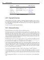
9.4
9.5
9.6
9.3.1 Basic Steps . . . . . . . . . . . . . . . . . . .
9.3.2 Program Structure . . . . . . . . . . . . . . .
9.3.3 Limitations and Troubleshooting . . . . . . . .
Code Generation for Visual Basic 6 (HALCON/COM)
9.4.1 Basic Steps . . . . . . . . . . . . . . . . . . .
9.4.2 Program Structure . . . . . . . . . . . . . . .
9.4.3 Limitations and Troubleshooting . . . . . . . .
Code Generation for C . . . . . . . . . . . . . . . . .
9.5.1 Basic Steps . . . . . . . . . . . . . . . . . . .
General Aspects of Code Generation . . . . . . . . . .
9.6.1 Arbitrary Program Code . . . . . . . . . . . .
9.6.2 Assignment . . . . . . . . . . . . . . . . . . .
9.6.3 Variable Names . . . . . . . . . . . . . . . . .
9.6.4 ’for’ Loops . . . . . . . . . . . . . . . . . . .
9.6.5 Protected Procedures . . . . . . . . . . . . . .
9.6.6 System Parameters . . . . . . . . . . . . . . .
9.6.7 Graphics Windows . . . . . . . . . . . . . . .
10 Miscellaneous
10.1 Keyboard Shortcuts . . . . . . . . . . .
10.1.1 HDevelop . . . . . . . . . . . .
10.1.2 Program Listing . . . . . . .
10.1.3 Help Window . . . . . . . . .
10.1.4 Graphics Window . . . . . . .
10.1.5 Variable Inspect . . . . . .
10.1.6 OCR Training File Browser
10.2 Online Help . . . . . . . . . . . . . . .
10.3 Emergency Backup . . . . . . . . . . .
.
.
.
.
.
.
.
.
.
.
.
.
.
.
.
.
.
.
.
.
.
.
.
.
.
.
.
.
.
.
.
.
.
.
.
.
.
.
.
.
.
.
.
.
.
.
.
.
.
.
.
.
.
.
.
.
.
.
.
.
.
.
.
.
.
.
.
.
.
.
.
.
.
.
.
.
.
.
.
.
.
.
.
.
.
.
.
.
.
.
.
.
.
.
.
.
.
.
.
.
.
.
.
.
.
.
.
.
.
.
.
.
.
.
.
.
.
.
.
.
.
.
.
.
.
.
.
.
.
.
.
.
.
.
.
.
.
.
.
.
.
.
.
.
.
.
.
.
.
.
.
.
.
.
.
.
.
.
.
.
.
.
.
.
.
.
.
.
.
.
.
.
.
.
.
.
.
.
.
.
.
.
.
.
.
.
.
.
.
.
.
.
.
.
.
.
.
.
.
.
.
.
.
.
.
.
.
.
.
.
.
.
.
.
.
.
.
.
.
.
.
.
.
.
.
.
.
.
.
.
.
.
.
.
.
.
.
.
.
.
.
.
.
.
.
.
.
.
.
.
.
.
.
.
.
.
.
.
.
.
.
.
.
.
.
.
.
.
.
.
.
.
.
.
.
.
.
.
.
.
.
.
.
.
.
.
.
.
.
.
.
.
.
.
.
.
.
.
.
.
.
.
.
.
.
.
.
.
.
.
.
.
.
.
.
.
.
.
.
.
.
.
.
.
.
.
.
.
.
.
.
.
.
.
.
.
.
.
.
.
.
.
.
.
.
.
.
.
.
.
.
.
.
.
.
.
.
.
.
.
.
.
.
.
.
.
.
.
.
.
.
.
.
.
.
.
.
.
386
387
388
388
389
389
390
391
391
392
392
393
394
394
395
395
395
.
.
.
.
.
.
.
.
.
.
.
.
.
.
.
.
.
.
.
.
.
.
.
.
.
.
.
.
.
.
.
.
.
.
.
.
.
.
.
.
.
.
.
.
.
.
.
.
.
.
.
.
.
.
.
.
.
.
.
.
.
.
.
.
.
.
.
.
.
.
.
.
.
.
.
.
.
.
.
.
.
.
.
.
.
.
.
.
.
.
.
.
.
.
.
.
.
.
.
.
.
.
.
.
.
.
.
.
.
.
.
.
.
.
.
.
.
.
.
.
.
.
.
.
.
.
.
.
.
.
.
.
.
.
.
.
.
.
.
.
.
.
.
.
.
.
.
.
.
.
.
.
.
.
.
.
.
.
.
.
.
.
397
397
397
401
402
402
402
402
403
403
A Glossary
405
B Command Line Usage
407
Index
411
11
Introduction
Introducing HDevelop
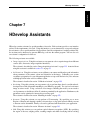
Chapter 1
Introducing HDevelop
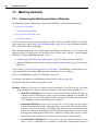
HDevelop is a tool box for building machine vision applications. It facilitates rapid prototyping by
offering a highly interactive programming environment for developing and testing machine vision applications. Based on the HALCON library, it is a versatile machine vision package suitable for product
development, research, and education.
There are four basic ways to develop image analysis applications using HDevelop:
• Rapid prototyping in the interactive environment HDevelop.
You can use HDevelop to find the optimal operators or parameters to solve your image analysis
task, and then build the application using various programming languages, e.g., C, C++, C#, Visual
Basic .NET, or Delphi.
• Development of an application that runs within HDevelop.
Using HDevelop, you can also develop a complete image analysis application and run it within the
HDevelop environment. The example programs supplied with HDevelop can be used as building
blocks for your own applications.
• Execution of HDevelop programs or procedures using HDevEngine.
You can directly execute HDevelop programs or procedures from an application written in C++
or any language that can integrate .NET or COM objects using HDevEngine. This is described in
detail in the Programmer’s Guide, part VII on page 209.
• Export of an application as C, C++, Visual Basic, Visual Basic .NET, or C# source code.
Finally, you can export an application developed in HDevelop as C, C++ , Visual Basic, Visual
Basic .NET, or C# source code. This program can then be compiled and linked with the HALCON
library so that it runs as a stand-alone (console) application. Of course, you can also extend the
generated code or integrate it into existing software.
Let’s start with some facts describing the main characteristics of HDevelop.
12
Introducing HDevelop
1.1
Facts about HDevelop
HDevelop actively supports your application development in many ways:
2 With the graphical user interface of HDevelop, operators and iconic objects can be directly selected, analyzed, and changed within a single environment.
2 HDevelop suggests operators for specific tasks. In addition, a thematically structured operator
list helps you to find an appropriate operator quickly.
2 An integrated online help contains information about each HALCON operator, such as a detailed
description of the functionality, typical successor and predecessor operators, complexity of the
operator, error handling, and examples of application. In addition, the online help provides a
search facility that allows to search the complete documentation of HALCON.
2 HDevelop comprises a program interpreter with edit and debug functions. It supports standard
programming features, such as procedures, loops, or conditional statements. Parameters can be
changed even while the program is running.
2 HDevelop immediately displays the results of operations. You can try different operators and/or
parameters, and immediately see the effect on the screen. Moreover, you can preview the results
of an operator without changing the program.
2 Several graphical tools allow to examine iconic and control data online. For example, you can
extract shape and gray value features by simply clicking onto the objects in the graphics window,
or inspect the histogram of an image interactively and apply real-time segmentation to select
parameters.
2 Built-in graphical assistants provide interactive interfaces to more complex machine vision tasks.
The assistants can also generate HDevelop code in the current program.
2 Variables with an automatic garbage collection are used to manage iconic objects or control
values.
1.2
HDevelop XL
In addition to the standard HDevelop, there is also a variant called HDevelop XL, which is based on
HALCON XL. The user interface is identical, but underneath HALCON XL is optimized for large images. In the remainder of this document, when we refer to HDevelop you can substitute HDevelop XL if
that is the variant you will be using.
1.3
Terminology & Usage
HDevelop adheres to well-established conventions and usage patterns regarding its graphical user interface. Most of the terminology explained here will have become second nature to most users and may
most likely be skimmed over.
1.3 Terminology & Usage
13
click A single click with the left mouse button,
e.g., to mark and select items or to activate buttons. To
select multiple items, hold down the Ctrl key and click the desired items. To select many items
from a list, click the first item, hold down the Shift key and click the last item. All intermediate
items are then also selected.
double-click Two quick successive clicks with the left mouse button, e.g., to open dialogs of selected
items. Double-clicks are mostly shortcuts for single clicks followed by an additional action.
right-click A single click with the right mouse button to access additional functionality of the user
interface, e.g., context-sensitive menus. Clicking the right mouse button also ends interactive
drawing functions in HDevelop.
drag Keeping the left mouse button pressed while moving the mouse and finally releasing the mouse
button. Typically used to move items, resize windows, select multiple items at once, e.g., program
lines, or to draw shapes.
drag-and-drop HDevelop supports drag-and-drop of image files and HDevelop programs from other
applications. You can, e.g., drag an HDevelop program icon from a file browser and drop it on the
HDevelop window to load it.
middle mouse button With three-button mice, the middle mouse button is used under UNIX to paste
text from the clipboard into text fields.
mouse wheel Most recent three-button mice combine the middle mouse button with a scrolling wheel.
HDevelop supports the mouse wheel in many places. The mouse wheel operates the GUI element under the mouse cursor. Using the mouse wheel you can, for instance, quickly scroll large
program listings, select values from lists or perform continuous zooming of displayed images. In
general, windows that provide a scroll bar can be quickly scrolled with the mouse wheel. Furthermore, the values of spinner boxes (text fields that expect numerical data) can be decremented and
incremented with the mouse wheel.
Keyboard Usage
HDevelop is very keyboard-friendly. Most functions of the graphical user interface that can be operated
using the mouse can be accessed from the keyboard as well. Many of the most important functions
are available through keyboard shortcuts, which are worthwhile memorizing. When programming with
HDevelop, keeping both hands on the keyboard can increase the productivity. Therefore, many navigational tasks like selecting parameter fields or selecting values from lists can easily be done using just the
keyboard. The most common keyboard functions are listed in the section 10.1 on page 397.
To make it easier for you to memorize the keyboard shortcuts, many of them are introduced by a common combination to indicate
related to the graphics window
the context. For example, many shortcuts
are introduced by pressing Ctrl+Shift+G followed by another key, e.g., Ctrl+Shift+G,Del clears the graphics
window.
Because it is often easier to keep Ctrl+Shift pressed when hitting the second key the alternative
Ctrl+Shift+G,Ctrl+Shift+Del is also allowed.
On Mac OS X, the command key is used instead of Ctrl .
Introduction
Mouse Usage
14
Introducing HDevelop
Windows and Window Managers
In the default window mode of HDevelop, windows can be freely moved inside the main window by
dragging the title bar. They can be resized by dragging the window border. Windows can be focused by
clicking inside the window area. This also raises the corresponding window to the front. Windows that
are completely covered by other windows can be brought to the front by selecting them from the Window
menu.
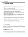
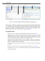
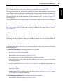
The window title provides some buttons with additional functionality. Clicking the icon in the left edge
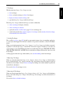
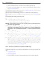
of the window title opens a menu from which all window management functions (move, resize, minimize...) can be selected. The buttons on the right edge of the window allow to 1) minimize/restore, 2)
maximize/restore, and 3) close the corresponding window (from left to right).
menu
maximize
minimize
close
Figure 1.1: Window title.
There is an alternative window mode called SDI (see also section 6.1 on page 54) which delegates the
functionality of handling the windows to the window manager.
Abbreviations
BP breakpoint
IC insert cursor
GUI graphical user interface
MDI multi-document interface
PC program counter
SDI single-document interface
XLD extended line description (see also chapter A on page 405)
Getting Started
15
Getting Started
2.1
Running HDevelop
In the following it is assumed that HALCON has already been installed as described in the Installation
Guide.
Windows
Under Windows, HDevelop is usually started from the Windows “Start” menu:
Start . Programs . MVTec HALCON 11.0 . HDevelop
You can also start HDevelop from the Windows Command Prompt or from the Start . Run... menu,
making it easy to pass optional command line switches:
hdevelop
Linux
Under Linux, HDevelop is started from the shell:
hdevelop &
Mac OS X
Under Mac OS X, HDevelop is started from the Applications folder of the Finder.
Command line switches (see below) are passed by calling HDevelop from a terminal window in the
following way:
/Applications/hdevelop.app/Contents/MacOS/hdevelop OPTIONS
Getting Started
Chapter 2
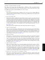
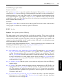
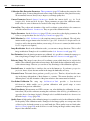
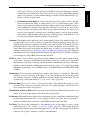
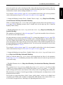
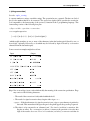
16
Getting Started
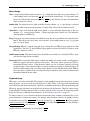
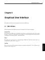
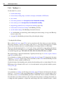
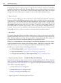
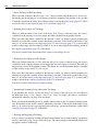
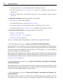
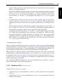
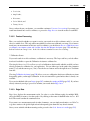
window title
menu
1. graphics window
2. operator window
4. variable window
3. program window
tool bar
status bar
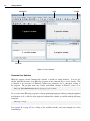
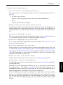
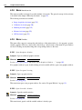
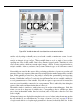
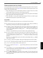
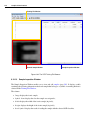
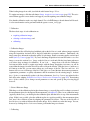
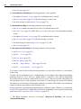
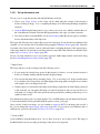
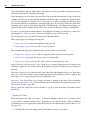
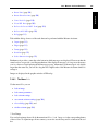
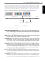
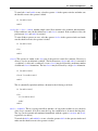
Figure 2.1: User interface.
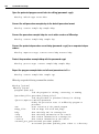
Command Line Switches
HDevelop supports several command line switches to modify its startup behavior. You can also
add the path and file name of an HDevelop program on the command line to load it directly. This
is identical to an invocation of HDevelop without any parameters and a subsequent loading of
the program. The program name may contain environment variables in Windows syntax as in:
hdevelop %HALCONEXAMPLES%/hdevelop/explore_halcon.hdev
Or, you can convert HDevelop programs to other programming languages without opening the graphical
user interface at all. A full list of the supported command line switches is available with the following
command:
hdevelop --help
See appendix B on page 407 for a listing of the available switches, and some example uses of the
command line.
2.1 Running HDevelop
17
User Interface
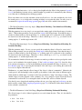
When HDevelop is started for the first time it looks similar to figure 2.1. The main window offers a menu
and a tool bar for quick access to frequently used functions. The status bar at the bottom of the window
displays messages and image properties. In addition, the following windows are available by default:
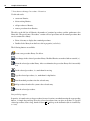
This window displays iconic data: images, regions, and XLDs. It provides its own tool bar to
quickly zoom and pan the displayed image, and a context menu to adapt the visualization settings.
The context menu is available by right-clicking inside the window1 It contains the most frequently
used entries from the menu Visualization. You can open multiple graphics windows. The one
marked with a lit bulb in the upper right corner is the active graphics window, i.e., it is the target
for subsequent display operations. The graphics window works like an image stack: Images can
be overlayed with regions or XLDs, or with images that have a reduced domain.
2. Operator window
You can select HALCON operators (and HDevelop procedures) in this window. The parameters
of the selected operator can be specified, and the operator can be executed, entered in the current
program, or both. You can also get online help for the selected operator from this window.
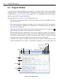
3. Program window
This window displays the current program. It provides syntax highlighting with user-definable
colors. The left column displays the program line numbers. The small black triangle is the insert
cursor, which is where new program lines will be added. In the following, it is referred to as
IC. The green arrow is the program counter which marks the next line to be executed. In the
following, the program counter is referred to as PC. You can also add or remove break points in
the current program in this column. These will halt the program execution at user-defined places
so that intermediate results may be examined.
The program source can be edited directly in this window provided that the full text editor is enabled (see section 6.4 on page 138). When adding new lines or modifying existing lines, advanced
autocompletion features speed up typing and help keeping the program consistent. Program lines
can also be modified by double-clicking them and editing them in the operator window. This is the
classical way to edit HDevelop programs. It is a more form-based approach to program editing.
Furthermore, different parameters can be easily tested in the operator window without changing
the program. Both the full text editor and the operator window can be used interchangeably for
program editing.
4. Variable window
Program variables can be watched in this window. It displays all variables of the current procedure
and their current values. Iconic variables are displayed as thumbnails, whereas control variables
are displayed as text. The layout of this window can be switched between horizontal and vertical
splitting by double-clicking the separator. You can double-click iconic variables to display them in
the active graphics window. Double-clicking control variables opens an inspection window with a
nicely formatted list of the current values and statistical data.
There are many other windows which will be covered later in this manual.
1 Unless the context menu has been disabled in the preferences to prevent any interference with interactive drawing functions.
See section 6.2.2.16 on page 76.
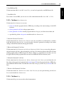
Examples
1. Graphics window
18
Getting Started
2.2
Running Example Programs
HALCON comes with a large number of HDevelop example programs from a variety of application
areas. These range from simple programs that demonstrate a single aspect of HALCON or HDevelop to
complete machine vision solutions. As an introduction to HDevelop we recommend to try some of these
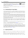
programs to quickly get accustomed to the way HDevelop works.
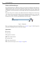
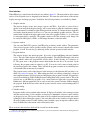
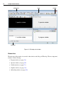
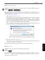
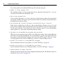
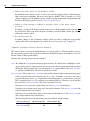
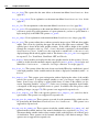
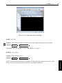
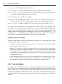
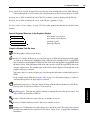
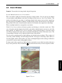
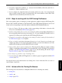
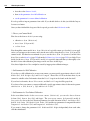
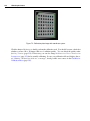
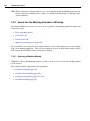
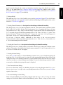
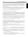
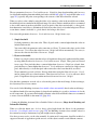
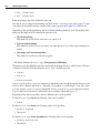
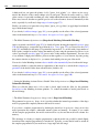
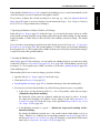
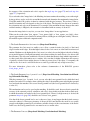
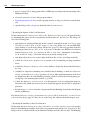
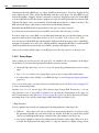
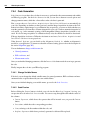
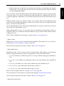
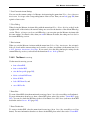
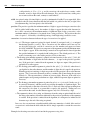
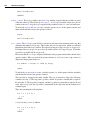
The example program “Explore the Power of HALCON” demonstrates many different capabilities of HALCON in one program. It can be started from the “Start” menu under Windows.
The Linux path to this program is $HALCONEXAMPLES/hdevelop/explore_halcon.hdev.
On Mac OS X, the path is /Users/Shared/Library/Application Support/HALCON11.0/examples/explore_halcon.hdev. Running this program is highly recommended to get
a good overview of the many application areas of HALCON.
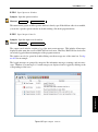
Click the ’Run’ button or press F5 to start the program
Figure 2.2: Explore the power of HALCON.
The example programs have been categorized by application area, industry, method, and operator usage.
A special category “New in version” groups examples by their appearance in specific HALCON releases.
Browsing these categories, you can quickly find example programs that cover image processing problems
2.2 Running Example Programs
19
Examples
that you may wish to solve with HALCON. These programs may serve as a foundation for your own
development projects.
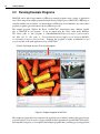
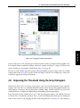
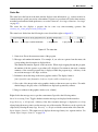
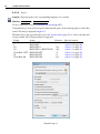
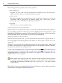
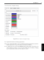
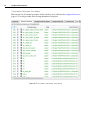
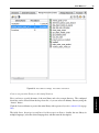
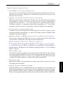
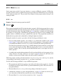
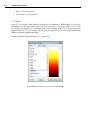
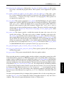
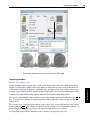
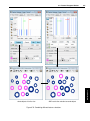
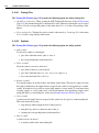
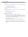
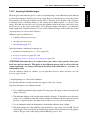
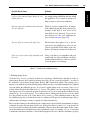
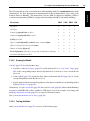
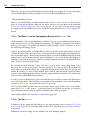
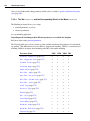
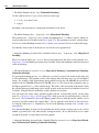
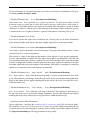
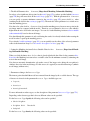
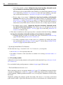
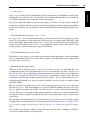
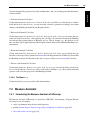
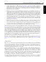
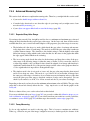
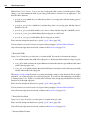
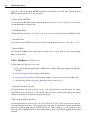
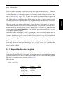
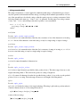
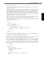
Figure 2.3: HDevelop program examples.
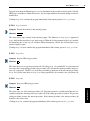
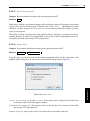
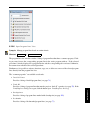
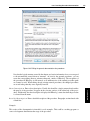
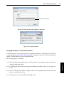
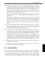
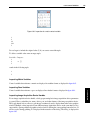
Browse and Load Example Programs
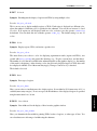
• Click File . Browse HDevelop Program Examples....
This will open the example program browser (see figure 2.3). Similar to a file browser, it shows
a tree of categories on the left and a list of example programs from the selected categories on the
right. Categories that contain hidden subtopics are marked with a +. Double-click on a category
label to open the subtopics (or click +). Double-click again to close the subtopics (or click -).
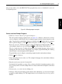
Browse the categories: Click on a category to select
it and display its example programs. You can
select multiple categories at once by holding the Ctrl key while clicking on the categories.
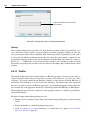
Filter the example programs: To reduce the amount of listed example programs, enter a word or
substring into the Find text field. Subsequently, only example programs matching this substring
in the file name or short description will be displayed.
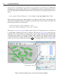
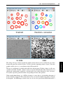
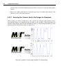
We pretend that you are looking for a measuring example from the semiconductor industry:
• Click on + next to Industry.
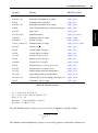
• Click on the subtopic Semiconductors. The examples belonging to the semiconductor industry
are listed on the right.
• Enter the word measure into the Find text field.
Note how the list is updated as you type. Now, you have a short list of example programs to select
from. You may need to resize the example browser to fully read the short descriptions of the listed
programs.
• Select measure_ic_leads.hdev by clicking on it.
• Click Open. The selected example program is then loaded. Alternatively, you can load an example
program by double-clicking on it. The example browser is closed unless Keep dialog open is
checked.
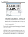
20
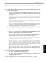
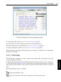
Getting Started
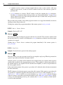
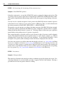
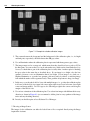
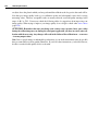
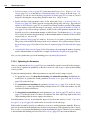
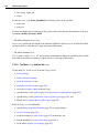
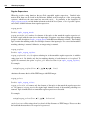
iconic variables (images, regions, XLDs)
control variables
PC (program counter)
current procedure
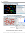
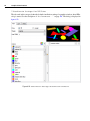
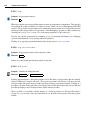
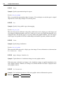
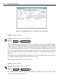
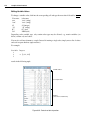
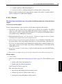
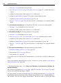
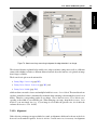
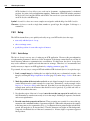
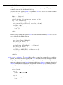
Figure 2.4: The variable and program window after loading the example program.
The program lines of the loaded example program are now displayed in the program window. The PC
is set to the first executable line of the program (leading comments are ignored). The variable window
is also updated: It lists the variables that are used in the main procedure, which is initially the current
procedure. The variables are currently uninstantiated, i.e., their current value is undefined. This is
indicated by the question mark (?). Both windows are displayed in figure 2.4.
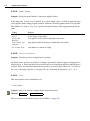
Run Example Program
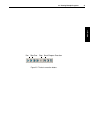
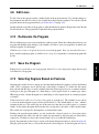
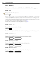
• Click Execute . Run or click the corresponding button from the tool bar (see figure 2.5).
The program line next to the PC is executed, the PC is moved to the following line and so forth
until the execution stops. There are four reasons for the program execution to stop: 1) the last
program line has been executed, 2) a breakpoint has been reached, 3) the HDevelop instruction
stop has been encountered as in this example, or 4) an error has occurred.
During execution, the graphics window is used for visualization. Changes to the variables are
reflected in the variable window. When the program execution stops, the status bar displays the
number of executed lines and the processing time.
To continue with the program execution, click Execute . Run again until the end of the program
is reached.
• Click Reset Program Execution to reset the program to its initial state. (see figure 2.5).
• Using the button Step Over you can execute the program line by line and inspect the immediate
effect of each instruction.
21
Examples
2.2 Running Example Programs
Run
Step Over
Stop
Reset Program Execution
Figure 2.5: The basic execution buttons.
22
Getting Started
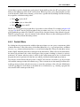
Acquiring Images with HDevelop
23
Chapter 3
Image acquisition is crucial for machine vision applications. It will usually be an early if not the first
step in your programming projects. This chapter explores the different ways of image acquisition in
HDevelop.
3.1
Reading Images From Files
Especially in the prototyping phase you often have a set of sample image files to work from. HDevelop
(or rather the underlying HALCON library) supports a wealth of image formats that can be loaded
directly (see read_image in the Reference Manual).
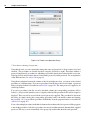
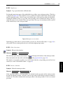
Drag-and-Drop
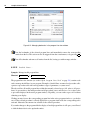
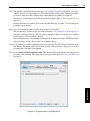
The easiest way to read an image is to simply drag it from a file browser to the HDevelop window and
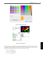
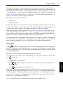
drop it there. When the file is dropped, HDevelop opens the dialog Read Image (see figure 3.1).
Figure 3.1: After dragging an image file onto the HDevelop window.
Image Acquisition
Acquiring Images with HDevelop
24
Acquiring Images with HDevelop
This dialog displays the full path of the image and automatically proposes a variable name derived from
the file name. This name can be edited, or another iconic variable name from the current program may
be selected from the drop-down list.
Furthermore, a preview of the image and basic image properties are displayed in the dialog (width,
height, color type, and number of channels). If you picked the wrong image, you can select another one
from the same directory by pressing the button next to the file name. This will open a file browser native
to the operating system, i.e., on Windows you may be able to switch to thumbnail view in this dialog.
When another image is selected, the dialog is updated accordingly.
When you click the button OK, the instruction read_image is added to the current program. With the
setting of Insert Position you determine where the instruction will be put: At the IC or the PC. If
you changed your mind about reading the selected image at all, click Cancel.
Drag-and-Drop of Multiple Images
You can also drag multiple images or directories containing multiple images to HDevelop. HDevelop
will then open an image acquisition assistant with the images preselected. See section 3.3 for further
information.
Images from Selected Directories
Apart from dragging and dropping images, there is an equivalent method from within HDevelop: Select
File . Read Image to get the dialog described above. Browse to and select the desired image from this
dialog, and click OK to add the selected image to your program.
3.2
Viewing Images
When images are read as described above, they are automatically displayed in the active graphics window. This is the default behavior in HDevelop, but the automatic display of images can be suppressed if
desired, e.g., to speed up computationally intensive programs.
Initially, the loaded image fills the graphics window entirely. The window itself is not resized so the
aspect ratio of the image might be skewed. Using the tool box of the graphics window you can easily
zoom the image, or change the window size with regard to the image.
We recommend to adapt the window size to the size of the image because otherwise the display is slowed
down. The image size, the window size and the displayed part of the image are set with the tool bar icons
of the graphics window (see figure 3.2).
An iconic view of the loaded image is also displayed in the variable window. When the image is cleared
in the graphics window, it can always be restored by double-clicking this icon.
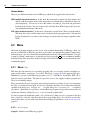
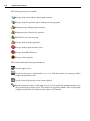
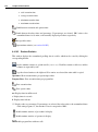
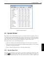
3.3 Image Acquisition Assistant
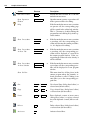
clear select magnify image size
pan image
zoom in/out
25
ROI tools
window size
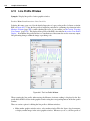
Figure 3.2: Tools in the graphics window.
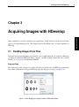
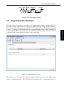
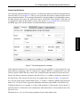
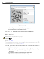
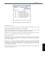
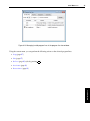
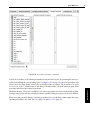
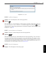
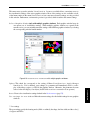
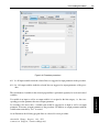
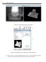
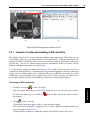
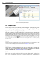
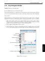
Image Acquisition Assistant
The image acquisition assistant is a powerful tool to acquire images from files (including AVI files),
directories or image acquisition devices supported by HALCON through image acquisition interfaces.
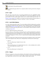
To use this assistant, select Assistants . Open New Image Acquisition. The window is displayed
in figure 3.3. It features several tab cards that can be stepped through one after another. Ultimately, the
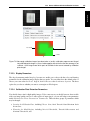
assistant generates HDevelop code that can be inserted into the current program. Select the entry Help
in the menu of the image acquisition assistant to open its online help.
Figure 3.3: Image acquisition assistant.
The tab card Source determines the acquisition method and the image source. In the default setting
images are acquired from files. This is described in the following section. Alternatively, images are
Image Acquisition
3.3
26
Acquiring Images with HDevelop
acquired from an image acquisition device, e.g., a camera. This is described in section 3.3.2 on page 28.
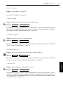
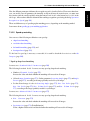
3.3.1
Acquiring Images From Files or Directories
You can specify a selection of image files or a directory to load images from. Make sure the radio button
Image File(s) is selected in the tab card Source. You can directly enter image names or the name of
a directory into the text field. Multiple image names are separated by a semicolon. Usually, it is more
convenient to use one of the following buttons:
Select File(s) ...
HDevelop opens a file selection dialog in the current working directory, displaying
the image files supported by HALCON. Multiple image files can be selected by holding down the Ctrl key while clicking
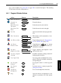
additional image files. Click Open to confirm the selection. The first selected image is displayed in the
active graphics window.
Select Directory ...
HDevelop opens a directory browser. It is not possible to select multiple directories. Confirm your
selection by clicking Open or OK. The first image from the selected directory is displayed in the active
graphics window. If the check box Recursive is ticked, all subdirectories of the specified directory are
scanned for images as well.
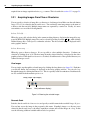
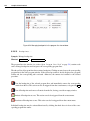
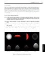
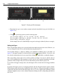
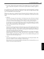
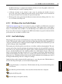
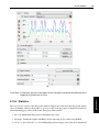
View Images
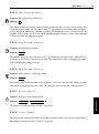
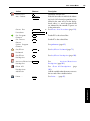
You can single-step through the selected images by clicking the Snap button (see figure 3.4). Each time
you click the button, the next image is displayed in the active graphics window. You can also loop
through the images by clicking the button Live. This is especially useful for animations. Both functions
are also available from the menu Acquisition.
Snap (single−step images)
Connect
Live (continuous display)
Figure 3.4: Browsing the selected images.
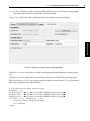
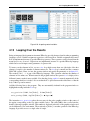
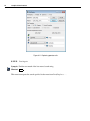
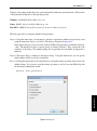
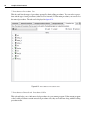
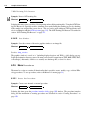
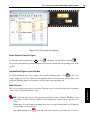
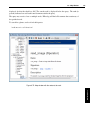
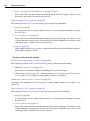
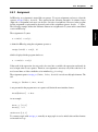
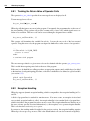
Generate Code
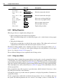
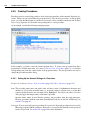
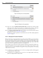
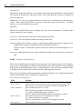
Switch to the tab card Code Generation, and specify a variable name in the text field Image Object.
You can later access the image in the program by this name. If multiple images or a directory were
selected in the tab card Source, the image acquisition assistant will read the images in a loop. In this
case the following additional variable names need to be specified:
3.3.1 Acquiring Images From Files or Directories
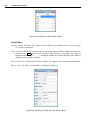
27
Loop Counter: The name of the loop index variable. While looping over the images in the program,
this variable will contain the object number of the current image.
Image Acquisition
Image Files: The name of the variable that will contain the names of the selected images.
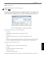
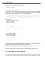
Figure 3.5: Specifying variable names for code generation.
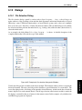
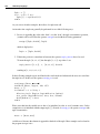
Click Code Preview to inspect the code that would be generated from the currently specified parameters.
Click Insert Code to generate the code and insert it at the position of the IC in the current program.
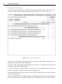
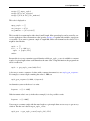
The following piece of code is an example generated from three selected images. It is a self-contained
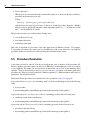
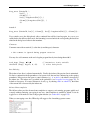
HDevelop program that runs without alteration.
* Code generated by Image Acquisition 01
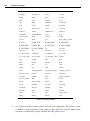
ImageFiles := []
ImageFiles[0] := 'C:/Program Files/MVTec/HALCON/images/fin1.png'
ImageFiles[1] := 'C:/Program Files/MVTec/HALCON/images/fin2.png'
ImageFiles[2] := 'C:/Program Files/MVTec/HALCON/images/fin3.png'
for Index := 0 to |ImageFiles| - 1 by 1
read_image (Image, ImageFiles[Index])
* Do something
endfor
28
Acquiring Images with HDevelop
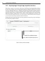
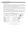
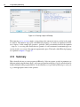
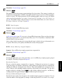
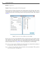
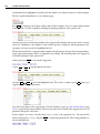
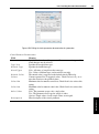
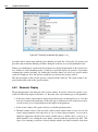
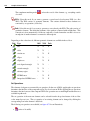
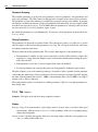
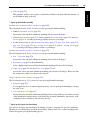
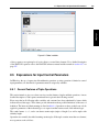
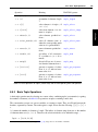
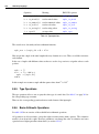
3.3.2
Acquiring Images Through Image Acquisition Interfaces
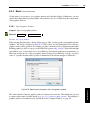
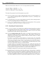
Select Image Acquisition Interface in the Source tab. The drop-down list below the radio button
becomes active. Initially, it lists all image acquisition interfaces supported by HALCON. You can tidy
this list by clicking the button Detect. HDevelop will then probe all the image acquisition interfaces
and remove those that do not respond. Probing the interfaces might cause the system to hang due to
erroneously installed drivers or hardware failures. If there are unsaved changes in the current program,
HDevelop will display a warning dialog. You are advised to save the changes before you proceed. You
can also ignore the warning and proceed, or abort the operation. After the interfaces have been probed,
you can select the desired image acquisition interface from the list.
Selecting the entry Help from the menu of the image acquisition assistant will open the online help for
the selected image acquisition interface.
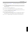
first, detect the available interfaces
then, select an interface from the list
Figure 3.6: Source selection (example).
3.3.2 Acquiring Images Through Image Acquisition Interfaces
29
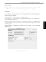
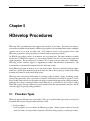
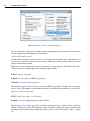
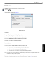
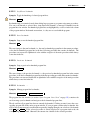
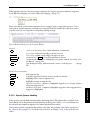
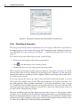
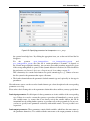
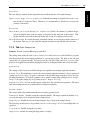
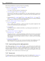
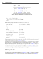
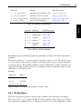
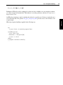
Connect to the Device
Image Acquisition
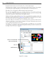
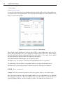
Once an image acquisition interface is selected, its connection parameters are detected and updated in the
tab card Connection (see figure 3.7). Here you can specify the device that is connected to the selected
image acquisition interface. If, for example, the interface of a frame grabber board with multiple cameras
has been selected as the source, the actual device can be selected here. The parameters of this tab card
are described in general in the reference section of the operator open_framegrabber; please refer to
the HTML page of the selected interface for detailed information (menu Help).
Figure 3.7: Connection parameters (example).
If the acquisition interface File is selected, two buttons become available to select an image file or an
image directory, respectively. The File interface also supports AVI files, or sequence files (.seq). The
latter are special to HALCON; they contain a list of image file names that will be loaded in succession.
Specify the desired connection parameters and click Connect to establish or update the connection to
the actual device. The connection status can also be toggled in the tool bar (see figure 3.4 on page 26).
You can grab single images with the button Snap, or switch to continuous grabbing mode using the
button Live. Live mode can be stopped by clicking the same button again which is now labeled Stop.
Clicking the button Detect attempts to re-detect valid parameters for the currently selected image acquisition interface. Usually, this is done automatically, when the interface is selected from the list on the
tab card Source.
The button Reset All sets all connection parameters back to their default values.
30
Acquiring Images with HDevelop
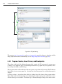
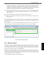
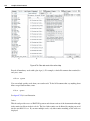
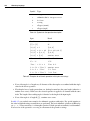
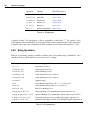
Set Device Parameters
The tab card Parameters contains a list of parameters specific to the selected device. It becomes
available once the connection to the device has been activated. See figure 3.8 for an example parameter
list. Please refer to the HTML page of the selected interface for detailed information. You can click the
help button of the assistant to get to the corresponding page automatically.
Depending on the parameter type, different selection methods are enabled. As an example, parameters
with a defined range of values can be specified by dragging a slider or entering the value parametrically.
If a value is changed, a reset button to the right is activated. Some parameters provide a check box which
attempts to set the parameter automatically if clicked.
If Update Image is checked, parameter changes are immediately reflected in the graphics window by
acquiring a new image. The button Refresh updates the list of parameters, which is useful if parameters
have side effects. You can reset all parameters to their default values at once by clicking Reset All.
acquire new image
at parameter
change
adjust displayed
parameters
reset parameter
Figure 3.8: Device-specific parameters (example).
3.3.2 Acquiring Images Through Image Acquisition Interfaces
31
Generate Code
On the tab card Code Generation the settings made in the other tab cards are turned into executable
code. The basic structure of the code and the corresponding variable names can be specified.
Control Flow
Initialization Only: Generate only code to initialize the image acquisition interface with the parameters specified in the other tab cards and to close it down properly. Additional code for image acquisition
and processing can be added later.
Acquire Single Image: Also generate code to acquire an image.
The image acquisition interface is addressed by a so-called handle. The variable name of this handle can
be specified in the text field Connection Handle. The variable name of the acquired image(s) can be
set in Image Object.
Click Code Preview to inspect the code. Click Insert Code to generate the code in the program
window at the IC.
Figure 3.9: Code generation.
Image Acquisition
Acquire Images in Loop: Also add a loop around the image acquisition code. Further image processing can be added inside this loop.
32
Acquiring Images with HDevelop
Here is a code example:
* Code generated by Image Acquisition 01
open_framegrabber ('GigEVision', 0, 0, 0, 0, 0, 0, 'progressive', -1, 'default', \
-1, 'false', 'default', 'NickName', 0, -1, AcqHandle)
grab_image_start (AcqHandle, -1)
while (true)
grab_image_async (Image, AcqHandle, -1)
* Do something
endwhile
close_framegrabber (AcqHandle)
3.3.3
Modifying the Generated Code
After the generated code has been inserted into the program window, HDevelop internally keeps the code
linked to the corresponding assistant. This link is kept until the assistant is quit using the menu entry
File . Exit Assistant. If you close the assistant using the menu entry File . Close Dialog or
using the close icon of the window, the assistant can be restored from the top of the menu Assistants.
You can change the settings inside the assistant and update the generated code accordingly. The code
preview will show you exactly how the generated code lines will be updated. Furthermore, you can
delete the generated code lines, or release them. When code lines are released, the internal links between
the assistant and those lines is cut off. Afterwards, the same assistant can generate additional code at a
different place in the current program.
Programming HDevelop
33
Chapter 4
Programming HDevelop
hdevelop -reset_preferences
This chapter deals with a simple example. Given is the image displayed in figure 4.1. The objective is to
count the clips and determine their orientation.
Figure 4.1: Paper clips.
4.1
Start a New Program
Start HDevelop or, if it is still running, click File . New Program to start a new program. HDevelop will
notify you if there are unsaved changes in the current program. If it does, click Discard to throw away
the changes and start anew. In case you rearranged the windows, click Window . Organize Windows
to restore the default layout displayed in figure 2.1 on page 16.
Programming
This chapter explains how to use HDevelop to develop your own machine vision applications. It is
meant to be actively followed in a running instance of HDevelop. In the following, it is assumed that the
preferences of HDevelop are set to the default values. This is always the case after a fresh installation
of HALCON. If you are uncertain about the current settings, you can always start HDevelop with the
default settings by invoking it from the command line in the following way (see also chapter 2 on page
15):
34
Programming HDevelop
The first thing to do is read the image and store it in an iconic variable. From the last chapter we know
that we can simply drag an image to the HDevelop window. We also know that this inserts the operator
read_image into the program. Therefore, we can just as well insert the operator directly.
4.2
Enter an Operator
Click into the text box of the operator
window, type read_image and press Return . You can also type
any partial operator name and press Return . HDevelop will then open a list of operators matching that
partial name. This way, you can easily select operators without having to type or even know the exact
name. Selection
is done with the mouse or using the arrow keys to highlight the desired operator and
pressing Return . If you selected the wrong operator by accident, you can reopen the list by clicking on
the drop-down arrow next to the operator name. When entering a partial name, operators commencing
with that name appear at the top of the list.
Figure 4.2: Matching operators after typing read_ and pressing Return.
4.3
Specify Parameters
After selecting an operator, its parameters are displayed in the operator window. They are grouped by
iconic and control parameters. The icons next to the parameter names denote the parameter type: Input
vs. output (see figure 4.3). The semantic type is displayed to the right of the parameters. Parameters are
specified in the text fields. The first parameter gets the input focus.
Enter Clip into the text field Image. The image will be stored in this variable. Next,enter ’clip’ into
the text field FileName. You can press Tab to go to the next input field. Pressing Shift+Tab takes you
back to the previous field. This way you can enter all parameters without using the mouse.
Click OK or press Return to submit the operator to the current program. This will do the following:
4.4 Getting Help
iconic output
35
semantic type
data type
control input
file selection dialog
Figure 4.3: Specifying parameters.
• An operator call is added as the first line of the current program.
• The program line is executed and the PC is advanced. To be more precise: All the lines from the
PC to the IC are executed which makes a difference when adding program lines in larger programs.
• The character * is added to the window title to indicate unsaved changes in the current program.
The current procedure (main) is also marked with * in the program window.
• The image is displayed in the graphics window.
• The status bar is updated, i.e., the execution time of the operator read_image is displayed and the
format of the loaded image is reported.
• The output variable Clip is created and displayed in the variable window.
• The operator window is cleared and ready for the insertion of the next operator.
4.4
Getting Help
You may be wondering where the clip image was loaded from since we did not specify any path or even
a file extension. This is a detail that is related to the way the HALCON operator read_image works.
HDevelop does not know anything about it. It just executes the operator with the parameters you supply.
Accessing the operator documentation from within HDevelop is very easy.
Double-click the first program line in the program window. The operator is displayed in the operator window for editing. Now click Help to open the HDevelop online help window. It will automatically jump to
the documentation of the displayed operator (see figure 4.4). The reference manual is completely crosslinked. The navigation at the left part of the window provides quick access to the documentation. The
Programming
• The IC is advanced, so that additional lines will be added after the inserted line.
36
Programming HDevelop
Figure 4.4: The online help window showing the documentation of the operator read_image.
tab card Contents presents the hierarchical structure of the documentation. The tab card Operators
lists all operators for direct access. Enter any desired substring into Find to quickly find an operator.
In the remainder of this chapter, try to use the online help as much as possible to get information about
the used operators. The online help window is described in section 6.8 on page 192.
4.5
Add Additional Program Lines
Select the clips by thresholding
Now, we want to separate the clips from the background, i.e., select them. They clearly stand out from
the background, thus a selection based on the gray value is appropriate. This operation is known as
thresholding.
Enter threshold into the operator window. This is both the full name of an operator and part of other
operator names.
Thus, you get a list of matching operators with threshold pre-selected when you press
Return
.
Press
Return once more to confirm the selected operator and show its parameters.
In figure 4.5 you can see that the input parameter Image is set to Clip automatically. For input variables
with no default value, reasonable suggestions are inferred automatically by collecting previous output
variables of the same type. Therefore, the name of the most recent matching output parameter will be
4.5 Add Additional Program Lines
37
Figure 4.5: Parameter suggestions.
Set MinGray and MaxGray to 0 and 30, respectively. This will select the dark pixels in the image.
Click Apply. This button executes the operator without adding it to the program. Additionally, it keeps
the current parameters open for editing. This way, you can easily try different settings and immediately
see the result. The selected pixels (the so-called region) are stored in the output variable Region, which
is displayed in the variable window. The region is an image mask: White pixels are selected while black
pixels are not.
The region is also displayed as an overlay in the graphics window. The selected pixels are displayed in
red (unless you changed the default settings).
The selected threshold values are not perfect, but we will correct this later. For now, click Enter to add
the operator to the program window. Contrary to clicking Ok, this does not execute the operator. Note
that the variable Region keeps its value but is no longer displayed in the graphics window. Also, the PC
is not advanced, indicating that the second line of the program is yet to be executed.
Adding program lines with Enter is especially useful if some of the input parameters use variable names
that will be added to the program at a later time.
Successor
Click on the just inserted program line to select it. You can let HDevelop suggest operators based on the
selected line. Open the menu Suggestions . Successors. This menu is filled dynamically to show
typical successors of the currently selected operator. We want to split the selected pixels into contiguous
regions. Move the mouse pointer over the menu entries. The status bar displays a short description of
the highlighted operator. Looking through the menu entries, the operator connection looks promising,
so we click on it. Any operator selected through this menu is transferred to the operator window.
Programming
suggested (most recent being the closest predecessor of the current program line). In this example, only
Clip is available.
38
Programming HDevelop
Again, the variable names suggested by HDevelop look reasonable, so press Return . This is equivalent
to clicking the Ok button (though this can be changed in the preferences of HDevelop). This time, two
program lines are executed: The threshold operation and the connection operation. As noted above:
Clicking Ok executes from the PC to the IC.
In the graphics window, the contiguous regions calculated by the operator connection are now displayed in alternating colors.
4.6
Understanding the Image Display
After having executed the three lines of our program, the graphics window actually displays three layers
of iconic variables: the image Clip, the region Region, and the tuple of regions ConnectedRegions
(from bottom to top). Place the mouse pointer over the icons in the variable window to obtain basic
information about the variables.
The display properties of images and the topmost region can be adjusted from the context menu of the
graphics window. For images, the look-up table (henceforth called LUT) and the display mode (referred
to as “paint”) can be set. The LUT specifies gray value mappings. Experiment with different settings:
Right-click in the graphics window and select some values from the menus Lut and Paint. Make
sure, the menu entry Apply Changes Immediately is checked. Notice how the display of the image
changes while the regions remain unchanged.
The menu entries Colored, Color, Draw, Line Width, and Shape change the display properties of
the topmost region. Set Draw to ‘margin’, Color to ‘cyan’, and Shape to ‘ellipse’. The display of
ConnectedRegions (which is the topmost layer) changes accordingly. The region Region is still displayed in filled red.
A more convenient way to set many display properties at once is available through the menu entry Set
Parameters.... It opens the settings window displayed in figure 4.6.
After trying some settings, click the button Reset to restore the default visualization settings.
You cannot change the display properties of regions (or XLDs) other than the topmost. What you can
do is rebuild the image stack in the graphics window manually by double-clicking iconic variables in
the variable window and changing the properties each time another layer is added. The stack is cleared
whenever an image is added that uses the full domain. To clear the stack (and thus the graphics window)
manually, click the clear icon (see figure 3.2 on page 25).
4.7
Inspecting Variables
When you move the mouse cursor over the variable ConnectedRegions you see that it contains 98
regions.
Right-click on the icon ConnectedRegions and select Clear / Display to display only the connected regions in the graphics window. Right-click again and select Display Content . Select....
This menu entry opens a variable inspection window which lists the contents of the variable
Figure 4.6: Changing the display parameters.
ConnectedRegions. The selected region of this inspection window is displayed in the graphics window using the current visualization settings. Set Draw to ‘margin’ and Shape to ‘ellipse’ and select some
regions from the list. An example is illustrated in figure 4.7 on page 40.
For now, close the variable inspection window. The large number of regions is due to the coarse setting
of the bounds of the threshold operator. In the following we will use one of HDevelop’s visual tools
to find more appropriate settings interactively.
4.8
Improving the Threshold Using the Gray Histogram
Click Visualization/Tools . Gray Histogram to open a tool for the inspection of gray value histograms. One of its uses is to determine threshold bounds visually. Because the graphics window currently displays only regions, the gray histogram is initially empty. Double-click the Clip icon in the
variable window to re-display the original image and watch its gray histogram appear.
Select Threshold in the column Operation of the gray histogram window, and click the icon next
to Threshold to visualize the operation. Now, you can try different threshold bounds by altering the
values in Min and Max or by dragging the lines in the histogram area (see figure 4.8). Any changes to
39
Programming
4.8 Improving the Threshold Using the Gray Histogram
40
Programming HDevelop
Figure 4.7: Interactive inspection of an iconic variable containing regions.
visualize threshold operation
Figure 4.8: Determining threshold bounds interactively using the gray histogram.
these values are immediately visualized in the active graphics window. The values 0 and 56 seem suitable
for the lower and upper bounds, respectively.
4.9 Edit Lines
4.9
41
Edit Lines
To edit a line in the operator window, double-click it in the program window. If you make changes to
the parameters and click Ok or Enter, the original line in the program is updated. You can also edit the
program directly in the program window (see section 6.4.2.2 on page 142).
Double-click the second line of the program to adjust the threshold operation. Replace the value 30 with
56 and click Enter. The program line is updated in the program window.
4.10
Re-Execute the Program
The last editing step was just a tiny modification of the program. Often, after editing many lines in your
program with perhaps many changes to the variables you want to reset your program to its initial state
and run it again to see the changes.
Click Execute . Reset Program Execution to reset the program. Now, you can select Execute .
Run to run the complete program, or click Execute . Step Over repeatedly to execute the program line
by line.
Save the Program
Perhaps now is a good time to save your program. Select File . Save and specify a target directory and
a file name for your program.
4.12
Selecting Regions Based on Features
Inspecting the variable ConnectedRegions after the changed threshold operation yields a much better
result. Still, a contiguous area at the left edge of the image is returned. To obtain only the regions
that coincide with the clips, we need to further reduce the found regions based on a common criterion.
Analogous to the gray histogram tool, which helps to select regions based on common gray values,
HDevelop provides a feature histogram tool, which helps to select regions based on common properties
or features.
Click Visualization/Tools . Feature Histogram to open the tool. The column Feature allows
to select the feature that the region selection will be based on. The default feature is “area”, which is
adequate in this case: The actual clips are all the same size, thus the area of the regions is a common
feature. In the feature histogram the horizontal axis corresponds to the values of the selected feature.
The vertical axis corresponds to the frequency of certain feature values.
Similar to the gray histogram window, you can visualize the selected regions, i.e., the regions whose
area falls between the values Min and Max, which are represented by the green and red vertical lines,
respectively. Click the icon next to the selected feature (area) to enable the visualization.
Specify the parameters in the Output section of the feature histogram window as shown in figure 4.9.
Drag the green and red line to see how this affects the selected regions. In the histogram we can see
Programming
4.11
42
Programming HDevelop
that in order to cover all the clips, we can safely select regions whose area is between, say, 4100 and the
maximum value in the histogram. When you are satisfied with the selection, click the button Insert
Code. The following line (with similar numeric values) will be added to your program at the position of
the IC:
select_shape (ConnectedRegions, SelectedRegions, 'area', 'and', 4100, 5964)
Run the program, and inspect the output variable SelectedRegions. The regions corresponding to the
clips are now determined correctly. To obtain the orientation and the center of gravity of the clips, add
the following operator calls to the program:
orientation_region (SelectedRegions, Phi)
area_center (SelectedRegions, Area, Row, Column)
The operator orientation_region returns a tuple of values: For each region in SelectedRegions
a corresponding orientation value in Phi is returned. The operator area_center in the same way
returns the area, row and column of each input region as tuples. Again, run the program and inspect the
calculated control variables. You can inspect multiple control variables in one inspection window. This
is especially useful if the control variables all relate
to each other as in this example. In the variable
window select all control variables (hold down the Ctrl key), and right-click Inspect (see figure 4.10).
get rid of this region
visualize feature selection
Figure 4.9: Selecting regions with a similar area in the feature histogram.
4.13 Looping Over the Results
43
Figure 4.10: Inspecting control variables.
Looping Over the Results
Being an integrated development environment, HDevelop provides features found in other programming
languages as well: Variable assignment, expressions, and control flow. Variable assignment and control
flow are implemented in terms of specific HDevelop operators. These operators can be selected from the
menu Operators . Control. Expressions are implemented in terms of a specific HDevelop language
which can be used in input control parameters of operator calls.
To iterate over the elements in Phi, we use a for loop which counts from zero (the index of the first
element of a tuple) to the number of elements minus one. The for loop is entered just like a common
HALCON operator: Enter for into the operator window and specify the parameters as in figure 4.11.
The notation |Phi| - 1 is part of the HDevelop language. This operation calculates the number of
elements in Phi minus one. When inserted in the program window, the operator for is displayed in a
different format to make it more readable. Note that the closing endfor is entered automatically if the
corresponding check box is ticked. Also note that the IC is placed between the added lines so that the
body of the loop can be entered.
Add the following lines to the program. They are automatically indented in the program window to
highlight the nesting inside the for loop.
set_tposition (3600, Row[Index], Column[Index])
write_string (3600, deg(Phi[Index]) + ' degrees')
The instruction set_tposition places the text cursor in the active graphics window at the center of
the region corresponding to the loop index variable Index. The value 3600 is the so-called window
handle of the target graphics window. This number is displayed in the title of the graphics window and
can be different in your environment. The notation Row[Index] is another operation of the HDevelop
language. It provides access to a single value of a tuple.
Programming
4.13
44
Programming HDevelop
Figure 4.11: Entering a loop in HDevelop.
The instruction write_string outputs a given string at the current text cursor position in the graphics window. The function deg is part of the HDevelop language. It converts its argument from radians to degrees. In this example the operation + performs a string concatenation because the argument
’ degrees’ is a string value. Before the two operands of + are concatenated, an automatic type conversion (double to string) of the numeric argument takes place. The details of the HDevelop language
are explained in chapter 8 on page 337.
4.14
Summary
This is basically the way to create programs in HDevelop. Select an operator, specify its parameters, try
different settings using the button Apply, add a new program line using Enter or Ok, and edit it later by
double-clicking it in the program window. Use the interactive tools provided by HDevelop to assist you,
e.g., to find appropriate values for the operators.
HDevelop Procedures
45
Chapter 5
HDevelop Procedures
HDevelop offers a mechanism for the creation and execution of procedures. Procedures are meant to
increase the readability and modularity of HDevelop programs by encapsulating functionality of multiple
operator calls in one or more procedure calls. It also makes it easier to reuse program code in other
HDevelop programs by storing repeatedly used functionality in external procedures.
An HDevelop procedure consists of an interface and a program body. Procedure interfaces resemble
the interfaces of HALCON operators, i.e., they contain parameter lists for iconic and control input and
output parameters. The procedure body contains a list of operator and procedure calls. Furthermore,
HDevelop provides extensive support to supplement procedures with structured documentation. The
documentation is automatically integrated into the online help system.
HDevelop offers all necessary mechanisms for creating, loading, deleting, copying, modifying, saving,
and exporting procedures. Once a procedure is created, it can basically be used like an operator: Calls to
the procedure can be added to any program body and be executed with the appropriate calling parameters.
Generally, the concept of using procedures inside HDevelop is an extension to the concept of calling
HALCON operators since procedure and operator interfaces have the same parameter categories, and the
same rules apply for passing calling parameters.
5.1
Procedure Types
HDevelop supports different types of procedures. The type is specified when a procedure is created, and
determines the location of the procedure in the file system.
• Local procedures
Local procedures are stored inside the HDevelop program. Each program contains at least the
“main” procedure. Local procedures cannot be called from other programs or external procedures.
Procedures
Every HDevelop program is made up of one or more procedures. It always contains the main procedure,
which has a special status inside the program, because it is always the top-most procedure in the calling
hierarchy and cannot be deleted from the program.
46
HDevelop Procedures
• External procedures
External procedures are stored as separate files. Each file contains exactly one external procedure.
External procedures can be shared between different HDevelop programs. The modification of an
external procedure immediately affects all HDevelop programs using it. The file name determines
the name of the procedure. Thus, if the file name of an external procedure is changed, programs
and other procedures using it will have to be adapted.
• Libraries
Libraries contain a collection of (typically related) procedures in a single file. They share the
same properties as a collection of external procedures in a single directory. By convention, the
term “external procedure” includes library procedures as well unless stated otherwise. The idea of
creating a library is to keep related procedures as a unit.
If the type of an existing procedure is changed, the procedure resolution might be affected (see section 5.5
on page 48).
5.2
File Types
HDevelop programs, procedures, and libraries are stored in files with different formats and extensions.
5.2.1
HDevelop Programs
.hdev (HALCON 10 or higher) This is the default file format for HDevelop programs, i.e. the “main”
procedure and all local procedures. It stores programs in XML format and is suitable for revision
control software.
If you intend to manage your HDevelop programs using revision control software, make sure to
suppress the program checksum which is generated by default, see preferences, Experienced
User (page 93). However, note that programs saved without the checksum cannot be loaded in the
demo version of HDevelop.
Please note that programs in this format are not supported in HDevelop versions up to and including HALCON 9.
.dev This is the default file format for HDevelop programs in HDevelop versions up to and including
HALCON 9. It is not suitable for managing programs using revision control software. This format
is required if you want to be able to load HDevelop programs in older versions of HDevelop.
5.2.2
External Procedures
.hdvp (HALCON 10 or higher) This is the default file format for external procedures. It stores external
procedures in XML format and is suitable for revision control software. Procedures with the
extension .hdvp always override procedures with the same name but the extension .dvp in the same
directory.
5.2.3 Libraries
47
.dvp This is the default file format for external procedures in HDevelop versions up to and including
HALCON 9. It is not suitable for managing external procedures using revision control software.
This format is required if you want to be able to use external procedures in older versions of
HDevelop.
The file name (without the extension) determines the name of the contained external procedure (see also
section 5.1 on page 45).
5.2.3
Libraries
.hdpl (HALCON 11 or higher) This is the file format for procedure libraries. It stores libraries in XML
format and is suitable for revision control software. Libraries were introduced in HALCON 11 and
cannot be used in older versions of HDevelop. Library procedures have to be converted to external
procedures in order to be accessible in older versions of HDevelop.
5.3
Procedure Scope
The scope of a procedure defines its visibility to other procedures. If a procedure is visibile, it can be
called and thus executed. The scope can be either private or public.
• Private scope
The procedure is only visible from procedures in the same directory or the same library. The scope
of local procedures is always private to the current program, i.e., external procedures or procedures
from libraries can never see them.
• Public scope
5.4
Procedure Locations
HDevelop looks for procedures in a set of directories. Please note that subdirectories are always searched
recursively.
• Standard procedure path
By default, HDevelop is set up to look for procedures in a predefined directory which contains
several useful procedures. The standard procedure path is %HALCONROOT%\procedures under
Windows and $HALCONROOT/procedures under UNIX/Mac OS X, Because many example programs shipped with HALCON rely on these procedures, the standard procedure path cannot be
removed, but it can be disabled to make the corresponding procedures unavailable.
• User-defined directories
Other arbitrary directories can be added or removed in the preferences of HDevelop. Just like the
standard procedure path, each user-defined directory can be enabled or disabled independently. The
user-defined directories and their settings are persistent, i.e., they survive a restart of HDevelop.
Procedures
The procedure is visible to all other procedures.
48
HDevelop Procedures
• Session directories
HDevelop can also be started from the command line with a set of directories that are searched for
procedures in the current session only.
Calling
hdevelop -external_proc_path:<path name(s)>
adds the directories given in path name(s) to the list of searched procedure directories. Multiple
directories may be specified by using the system-dependent separator, i.e., “;” on Windows systems
and “:” on Linux/Mac OS X systems.
The procedure locations are searched in the following order:
• session directories (if any)
• user-defined directories
• standard procedure path
This order is important if a procedure of the same name exists in different locations. For example:
If a program uses external procedures and you run HDevelop with session directories, any duplicate
procedures in the session directories will block the path to the intended procedures.
5.5
Procedure Resolution
A procedure can only be called if it can be resolved from the point of insertion of the procedure call.
Because duplicate procedure names are allowed in HDevelop, understanding the order of resolution
is very important. Procedures are resolved based on their name only and not on the matching of the
signature. Thus, in the following a matching procedure refers to a procedure of the name given in the
procedure call. If the resolved procedure has a different signature (i.e., different number and/or types of
parameters), the call will be invalid.
External and library procedures are searched in the order specified in section 5.4 on page 47.
A procedure call in a local procedure (including “main”) looks for a matching procedure in the following
order:
• local procedure
• first matching public external/library procedure in the external procedure path list
A procedure call in an external procedure looks for a matching procedure in the following order:
• external procedure in the same directory
• first matching public external/library procedure in the external procedure path list
A procedure call in a library procedure looks for a matching procedure in the following order:
• procedure of the same library
• first matching public external/library procedure in the external procedure path list.
5.6 Protected Procedures
49
As an example we look at a program with three local procedures. Two procedure directories are defined
(disregarding the standard procedure path).
In procedure
main
project/visualization.hdpl/setup
common/config
main
project/visualization.hdpl/init
compute_results
project/setup
5.6
public
private
public
library
private
private
public
public
a call to
init
init
init
process
process
local
local
resolves to
init (local procedure in example.hdev)
project/visualization.hdpl/init
project/init
project/visualization.hdpl/process
project/local
Protected Procedures
Procedures can be protected by a password. The interface, documentation, and bodies of protected
procedures can only be accessed if the correct password is supplied. Protected procedures can be used
(i.e., called) by all users but viewed and modified only by those who know the password.
Instead of protecting single procedures individually, all procedures of an HDevelop program or a library,
respectively, can also be protected as a whole.
Protected procedures alter between two states:
Procedures
+ C:/Users/Public/
|
+--+ example.hdev
| |
| +--- main
| +--- init
| +--- compute_results
|
+--+ procedures/project/
| |
| +--- init.hdvp
| +--- local.hdvp
| +--- setup.hdvp
| |
| +--+ visualization.hdpl
|
|
|
+--- init
|
+--- process
|
+--- setup
|
+--+ procedures/common/
|
+--- config.hdvp
50
HDevelop Procedures
• locked
A protected procedure is locked if the password has not been entered in the current session. Locked
procedures cannot be modified, and the program code is not visible in the program window.
• unlocked
A protected procedure is unlocked after the correct password has been entered. Unlocked procedures may be modified, and the program code is visible in the program window.
To protect individual procedures, see section 6.4.9 on page 162.
To manage the protection state of multiple procedures, see section 6.2.2.16 on page 88).
5.7
Procedure Documentation
HDevelop procedures can be documented like operators. The documentation may include a detailed
description of the functionality of the procedure, example code, links to other procedures or operators,
and concise documentation of each parameter.
In order to manage a large collection of procedures, the procedures can be ordered in a hierarchical way,
i.e., procedures can be ordered by chapters and sections just like operators.
See section 6.4.8 on page 158 for details.
Graphical User Interface
51
Chapter 6
Graphical User Interface
This chapter is the reference to the graphical user interface of HDevelop.
6.1
Main Window
The main window handles HDevelop programs. It comprises the following components:
Window Title
The main window of HDevelop is identified by the title HDevelop followed by the name of the current
program (or unnamed if no file name has been specified yet). Unsaved changes in the current program
are indicated with a trailing asterisk (*) in the window title.
Menu
The menu at the top provides access to the functionality of HDevelop. The menus and their entries are
described in the section “Menu” on page 54.
The tool bar icons provide convenient shortcuts for frequently used functions. It is described in the
section “Tool Bar” on page 136.
GUI Reference
Tool Bar
52
Graphical User Interface
window title
menu
1. graphics window
2. operator window
4. variable window
3. program window
tool bar
status bar
Figure 6.1: HDevelop main window.
Window Area
The main part of the window is reserved for the windows and dialogs of HDevelop. The most important
windows are the following:
• Program window (see page 138)
• Operator window (see page 167)
• Variable window (see page 171)
• Graphics window (see page 182)
• Online help window (see page 192)
6.1 Main Window
53
Status Bar
The status bar at the bottom of the main window displays status information, e.g., context-sensitive information about a specific user action or the runtime of operator or procedure calls (unless time measurement has been deactivated in the preferences, see section “Runtime Settings -> Runtime Settings”
on page 95).
The status bar also displays a progress bar for some very time-consuming operators like
trainf_ocr_class_mlp or train_class_svm.
The status bar is divided into the following five areas (from left to right, see figure 6.2):
1. run status
2. messages / runtime information
3. image details
4. gray value
5. coordinates
Figure 6.2: The status bar.
1. Status icon: Shows the current run status of the program.
2. Messages and runtime information. For example, if you select an operator from the menu, the
corresponding short description is displayed here.
The runtime information depends on the run mode: When single-stepping through the program,
the runtime of the last operator or procedure call is displayed. In continuous run mode, a runtime
summary of the executed program lines is displayed when the program stops. A history of the
most recent messages is also kept, see below.
3. Information about the image in the active graphics window. The display format is
[index] variable name (#=number of objects: height x width x channels x type)
4. Gray value of the image in the active graphics window at the mouse cursor position. For multichannel images, the gray values of all channels are displayed separated by commas.
5. Image coordinates in the graphics window (row, column).
Show Processing Time: Toggles whether execution messages are displayed in the status bar.
Copy History to Clipboard: A history of the latest execution messages is displayed as a tool tip
when placing the mouse pointer over the message area of the status bar. The history can be copied to the
clipboard by selecting the entry Copy History to Clipboard in the context menu of the status bar.
Open Output Console: The output console displays the message history in a separate window. See
section “Open Output Console” on page 129.
GUI Reference
Right-click in the message area to open the context menu. It provides the following entries:
54
Graphical User Interface
Window Modes
There are two different window modes in HDevelop, which can be toggled in the menu Window:
MDI (multiple-document interface): In this mode the main window contains all other windows and
dialogs (with the exception of the online help window and modal dialogs which block other windows temporarily). You are free to move the windows according to your needs and preferences
inside the main window. You may iconify and/or deiconify them. HDevelop provides basic window management functions in this mode.
SDI (single-document interface): In this mode, all windows are stand-alone. There is no main window.
The menu, the tool bar, and the status bar are relocated to the first program window. You may find
this mode beneficial if you want to take advantage of special window manager capabilities under
UNIX.
6.2
Menu
The menu of the main window provides access to the complete functionality of HDevelop. Here, you
may choose HALCON or HDevelop operators or procedures, or manipulate the graphical output. Every
menu item opens a pull-down menu (henceforth abbreviated as menu) with
optional submenus. You open
a menu by clicking a menu item or via the keyboard (by pressing the Alt key in combination with the
underlined letter of the menu item). In the following sections the menu entries are described in the order
in which they appear.
6.2.1
Menu File
This menu provides functions to load existing programs and to save recently created or modified programs and procedures, respectively. See section “File Types” on page 46 for the supported file types.
Furthermore, you may export HDevelop programs to C++, C, Visual Basic, Visual Basic .NET, C#, or
plain text and also print them. The menu also provides access to the supplied example programs and
allows to read arbitrary images.
Please note that the file type of programs and external procedures is persistent: If you load a program in
the older .dev format and save it again, it will not be converted to the newer .hdev format unless explicitly
specified in the dialog Save Program As... (or in the dialog Save Procedure As... for external
procedures). Additionally, it is possible to convert HDevelop programs and procedures between the old
and the new format by calling hdevelop -convert from the command line.
For new programs, the default file format (.hdev) will be used. When you save a program for the first
time, you can also select the older file format in the corresponding dialog. If you want to use the older
format all the time, you can make it the default by modifying the preferences, see General Options
(page 91).
6.2.1.1 New Program
Synopsis: Initialize a new HDevelop program.
6.2.1 Menu File
55
Checks for: Unsaved changes (page 222)
Shortcut: Ctrl+N This menu item deletes the current program including all local procedures. The contents of variables are
deleted before removing them. In addition, all graphics windows except one are closed. The last graphics
window is cleared. The display parameters for the remaining graphics window are reset to the default
values stored in the preferences (see section “Visualization Settings -> Pen / LUT / Paint” on
page 94). The runtime settings of the preferences are reset to their default values (see section “Runtime
Settings -> Runtime Settings” on page 95).
6.2.1.2 Open Program...
Synopsis: Load an existing HDevelop program.
Checks for: Unsaved changes (page 222)
Shortcut: Ctrl+O A file selection dialog (page 221) pops up to select an HDevelop program. Please note that only native
HDevelop programs (.hdev or .dev) can be loaded. Thus, text, C, C++, Visual Basic, Visual Basic .NET,
and C# versions of a file are rejected.
After you have loaded a program, the corresponding file name is added to the top of the menu Recent
Programs. This allows you to quickly switch between recently loaded programs.
6.2.1.3 Browse HDevelop Program Examples...
Synopsis: Select an HDevelop example program from a categorized list.
Checks for: Unsaved changes (page 222)
Shortcut: Ctrl+E Selecting this menu item opens a dialog that allows you to load HDevelop example programs grouped
by categories. The dialog is displayed in figure 6.3.
The tree on the left contains a structured list of categories. Clicking the icon in front of a category
toggles the display of its children. Alternatively, double-clicking any category label shows and hides the
subcategories while also selecting the node of the tree. There can be multiple levels of categories. If you
select a category, all its matching example programs are listed in the area on the right. You can select
multiple categories by holding down the Ctrl key while clicking additional categories. An HDevelop
example program may appear multiple times under different topics and categories.
Filtering the Matched Example Programs
Both the file name and the short description of the matched example programs are displayed. You can
reduce the number of listed programs by entering a search string into the Filter text box. As you type,
GUI Reference
Browsing the Categories
56
Graphical User Interface
Figure 6.3: Browse HDevelop Program Examples....
the list is updated to contain only example programs matching the string in either the file name or the
short description field. The filtering is case-insensitive.
Loading an Example Program
Double-click an example program in the list, or select it and click the button Open. Clicking Open in
new HDevelop opens the program in a new instance of HDevelop, which is useful if there are unsaved
changes in the current program.
Either way, you can keep the dialog open by checking the corresponding box beforehand. This can be
useful if you wish to scan through several example programs quickly.
6.2.1.4 Recent Programs
Synopsis: Load recently used HDevelop programs.
Checks for: Unsaved changes (page 222)
This submenu contains a list of the most recently used HDevelop programs. Simply click on a program
name to load it. The number of entries in this menu may be customized in the preferences (see General
Options -> General Options).
6.2.1.5 Open Procedure for Editing...
Synopsis: Load an existing external procedure or library.
From the file selection dialog (page 221) an arbitrary external procedure or library can be selected for
editing. If a library is selected, all included procedures are loaded for editing. Procedures opened through
this dialog need not be part of the configured procedure locations (section “Procedure Locations” on page
47).
6.2.1 Menu File
57
6.2.1.6 Close Procedure
Synopsis: Close an HDevelop procedure.
6.2.1.7 Close all Procedures
Synopsis: Close all HDevelop procedures.
6.2.1.8 Insert Program
Synopsis: Insert (parts of) another HDevelop program into the current program.
Selecting an entry in this submenu opens a file selection dialog (page 221) for the selection of an HDevelop program.
2 Insert All...
Synopsis: Insert a complete HDevelop program into the current program.
The main procedure of the selected program is inserted at the IC. All local procedures of the selected
program are added to the current program.
If the names of inserted local procedures clash with those of existing local procedures, the former are
renamed by appending the suffix _COPY_1 (or _COPY_2, _COPY_3... for subsequent insertions).
Note that inserted local procedures will conceal loaded external procedures with the same name, i.e.,
calls to the now hidden external procedures will have to be adapted. See Menu Procedures . Manage
Procedures... . External Procedures (page 84) to find out if your program contains hidden external procedures.
2 Insert Procedures...
Via this menu item you can add local procedures from an HDevelop program to the current program. All
local procedures except the main procedure are loaded from the selected file.
If the names of inserted local procedures clash with those of existing local procedures, the former are
renamed by appending the suffix _COPY_1 (or _COPY_2, _COPY_3... for subsequent insertions).
Note that inserted local procedures will conceal loaded external procedures with the same name, i.e.,
calls to the now hidden external procedures will have to be adapted. See Menu Procedures . Manage
Procedures... . External Procedures (page 84) to find out if your program contains hidden external procedures.
GUI Reference
Synopsis: Insert local procedures of the selected program into the current program.
58
Graphical User Interface
2 Insert Mainbody...
Synopsis: Insert only the main procedure of the selected program into the current program.
Insert the main body of the selected program at the IC. No local procedures are imported. If the current
program does not provide the procedures used in the imported program, the corresponding program lines
are marked as invalid code and will not be executed. Invalid code is turned into valid code by providing
the missing procedures.
6.2.1.9 Save
Synopsis: Save changes of the current HDevelop program or the currently selected external procedure.
Shortcut: Ctrl+S The actual functionality of this menu entry depends on the selected procedure in the program window:
• Main or local procedure selected in program window:
Save changes of the current HDevelop program. If no file name has been specified yet, a file selection dialog (page 221) will be opened where you can specify the program name and optionally the
file format (see section “File Types” on page 46). Local procedures are saved within the HDevelop
program.
The file name of the program you save is added to the menu Recent Programs.
Please note that modified external procedures are not saved automatically. To save them as well,
select the menu entry Menu File . Save All, or select the corresponding external procedure in
the program window and click Menu File . Save again (see below).
• External procedure selected in program window:
Save changes to the currently selected external procedure back to the originating file. The operation
is done quietly. A modified external procedure is marked with an asterisk (*) in the program
window.
If you try to save a file that has been modified outside of your running instance of HDevelop (possibly by
another user), a warning message is displayed asking whether you want to overwrite the file. If you are
uncertain about the external changes to the file, it is recommended to click No, and save your program
under a different name using Save Program As....
6.2.1.10 Save Program As...
Synopsis: Save the current HDevelop program to a new file.
Shortcut: Ctrl+Shift+S A file selection dialog (page 221) is opened. You can specify a new file name and optionally a file format
(see section “File Types” on page 46), and save the current program under that name. The new file name
becomes the default name of the current program so that subsequent Save operations will use that name
instead of the old.
The file name of the program you save is added to the menu Recent Programs.
6.2.1 Menu File
59
6.2.1.11 Save Procedure As...
Synopsis: Save the current procedure as an external procedure or as a stand-alone HDevelop program.
Shortcut: Ctrl+Shift+P,S or Ctrl+Shift+P,Ctrl+Shift+S Using this menu entry you can save the currently selected procedure as an external procedure or an
HDevelop program. A file selection dialog (page 221) is opened where you can select the file type (see
also section “File Types” on page 46):
• HDevelop procedures (*.hdvp or *.dvp)
The procedure is saved as an external procedure. If the target directory is not already configured
in the external procedure directories (see Menu Edit . Preferences..., Directories (page
82)), HDevelop will suggest adding the directory to the list. An example dialog is displayed in
figure 6.4. If you click No, HDevelop will not be able to access the saved procedure unless the
directory is later added to the external procedure locations manually.
This is one method to make an internal procedure external. If you do not change the name of the
procedure, the internal procedure will conceal the external procedure.
Figure 6.4: Adding a new directory to the list of external procedure directories.
• HDevelop local procedure (*.hdev or *.dev)
If this file type is selected, an empty main procedure is added to the target file, and the procedure
is added to the program as a local procedure.
6.2.1.12 Save All
Synopsis: Save the current program and all modified external procedures.
Shortcut: Ctrl+Alt+S If no name has been specified for the current program yet, the behavior is similar to that of Save
Program As.... In addition, all modified external procedures marked with an asterisk (*) in the program window’s combo box are saved.
GUI Reference
This menu item is disabled if the main procedure is selected in the program window.
60
Graphical User Interface
6.2.1.13 Export
Synopsis: Export program code to a programming language or as a text file.
Shortcut: Ctrl+Shift+O,X or Ctrl+Shift+O,Ctrl+Shift+X See also: hdevelop -convert (command line switch (page 407)).
Using this dialog, you can select an export format and write (parts of) the current program to a file in that
format. The dialog is displayed in figure 6.5.
The button next to the export file name opens a file selection dialog (page 221) to select a file name and
an export format. The following formats are supported:
Format
Text File
C
C++
C++
Visual Basic .NET
C#
Visual Basic 6.0
Syntax
HALCON/HDevelop
HALCON/C
HALCON/C++
HALCON/C++ (HALCON 10)
HALCON/.NET
HALCON/.NET
HALCON/COM
Extension
.txt
.c
.cpp
.cpp
.vb
.cs
.bas
Figure 6.5: Export.
More information
Plain text export
section 9.5 on page 391
section 9.1 on page 381
section 9.1 on page 381
section 9.3 on page 386
section 9.2 on page 384
section 9.4 on page 388
6.2.1 Menu File
61
The file name extension corresponding to the selected export format is appended to the specified file
name.
Export Range: The export range specifies which parts of the current program are to be exported. The
following options are available:
• Program: The entire program is exported (main procedure and all local procedures). All
used external procedures are exported depending on the setting of the external procedure
options (see below).
• Current Procedure: The current procedure and all used local procedures are exported.
All used external procedures are exported depending on the setting of the external procedure
options (see below).
• External Procedures: All external procedures are exported depending on the setting of
the external procedure options (see below).
• Current Library: The current library is exported (all procedures that are part of the current library). All used external procedures (that are not part of the current library) are exported depending on the setting of the external procedure options (see below).
The short description and chapter information of procedures are exported as comments. Arbitrary
code can be embedded with special comment lines (see section 9.6 on page 392).
Procedure Options: Defines the export behavior for procedures.
• Export local procedures body: If checked, both the declaration and the body of local
procedures is exported. Otherwise, only the declaration is exported.
• Export external procedures body: If checked, both the declaration and the body of
external procedures is exported. Otherwise, only the declaration is exported.
• Export all referenced external procedures: Determines, if all referenced (i.e.,
used) external procedures are also exported with the current program.
• Export only if procedure is newer than export file: Export only those procedures to separate files whose time stamp is newer than the time stamp of the destination
file.
Window Export: Specifies the export behavior of HALCON windows:
• Use HALCON Windows: Export as a stand-alone project.
• Use Export Template (HALCON/.NET and HALCON/COM only): Export as a project
using the supplied project template.
Encoding: Specifies the encoding of exported programs. The following options are available:
GUI Reference
• External Procedures Destination: By default, external procedures are exported to a
single file. Select Separate Files to export external procedures to separate files. The file
name corresponds to the procedure name while the file extension is derived from the export
format. Select Separate or Library Files to export external procedures to separate
files but keep the files of libraries together in a single file.
62
Graphical User Interface
Figure 6.6: Read Image.
• Native: Export in the encoding defined by the operating system.
• UTF-8: Force export in UTF-8 encoding (Unicode).
Keep dialog open Checking this box keeps the dialog open for subsequent exports.
6.2.1.14 Read Image
Synopsis: Add an image file to the current program.
Shortcut: Ctrl+R See also: read_image.
This menu entry provides a quick way to open an image file and access it in the current program. The
associated dialog Read Image is displayed in figure 6.6.
File Name You can enter the name of an image file into this field. A relative file name is looked up in
several directories in that order:
1. The current working directory (., a single dot), i.e., the directory HDevelop was started from.
2. The subdirectory images of the directory specified by the environment variable
HALCONROOT.
3. The directories specified by the environment variable HALCONIMAGES.
4. The directories used in previous invocations of Read Image.
6.2.1 Menu File
63
The first matching image file is displayed as a thumbnail preview along with its width, height,
color type and number of channels.
Alternatively, open a file selection dialog (page 221) by selecting a predefined directory from the
File Name combo box or clicking the browse button. The latter will start browsing in the current
working directory, or in the last used directory. Depending on the operating system you may be
able to switch to a thumbnail view in the file selection dialog.
Variable Name HDevelop suggests a variable name derived from the selected file name. You may
adopt or edit this name. If you want to use a name of an already created iconic variable, this
combo box offers you all known iconic variable names. Simply click the arrow on the right side of
the combo box to select a variable name. Note that the reuse of a variable deletes the old content
and replaces it with the new image.
After selecting a file name, click OK to load the image into HDevelop. The operator read_image is
inserted at the specified insert position (IC or PC). The specified iconic variable is updated in the variable
window and the image is displayed in the active graphics window. Clicking Cancel aborts the operation.
By default, an absolute path to the selected image is inserted. You can instruct HDevelop to use relative
path names (see General Options -> General Options in the preferences).
6.2.1.15 Cleanup
Synopsis: Clean up allocated resources that are no longer being used.
See also: iconic variables (page 173), control variables (page 176).
GUI Reference
This menu item deletes all unused variables (iconic and control data) from the current procedure. These
are variables in the variable window that are no longer used in any operator or procedure call in the
current procedure body. This can happen after the deletion of program lines or after editing variable
names, because the corresponding variables are not deleted automatically. You may use this menu item
during a longer editing session to reorganize your variable window (page 171).
64
Graphical User Interface
6.2.1.16 Properties...
Synopsis: Display various properties of the current program.
The tab card General displays file properties of the current program, such as file name, path, creation
and modification date, and write permission. It also shows the file size, the number of lines of code, used
and unused local procedures, used external procedures and used protected procedures. This is displayed
in figure 6.7.
Figure 6.7: Properties: General (left), Used Modules (right).
The tab card Used Modules lists the HALCON modules used by the current program. Modules marked
with a lit bulb are used. This window allows you to get an estimate of how many modules your application will need in a runtime license. Please refer to the Installation Guide for more information about
modules and runtime licenses. See figure 6.7 for the corresponding dialog of an OCR example.
Check only used procedures If checked, only used procedures are considered for the evaluation of
the used modules. Otherwise, all procedures are considered.
Copy to Clipboard Copy the names of the used modules to the system clipboard. This way the list
can be easily pasted into other applications.
6.2.1 Menu File
65
6.2.1.17 Print...
Synopsis: Print the current program or selected procedures.
Shortcut: Ctrl+P The print dialog is displayed in figure 6.8.
Figure 6.8: Print.
Print Range
Program Complete program including all procedures.
Current Procedure Current procedure and its used procedures.
Selection Highlighted program lines and their used procedures.
External Procedures All external procedures.
Print Procedures Define whether procedures are printed or not.
• Used Local Procedures: print only used local procedures.
• All Local Procedures: print all local procedures.
• Used External Procedures: also print used external procedures.
Only Procedure Interface If this box is checked, the procedure body is not printed. Instead, only
the interface of the procedure is printed.
The bodies of locked procedures (see section “Protected Procedures” on page 49) are not printed.
GUI Reference
Procedure Options
66
Graphical User Interface
6.2.1.18 Quit
Synopsis: Quit HDevelop.
Checks for: Unsaved changes (page 222)
Shortcut: Ctrl+Q See also: exit.
This menu item terminates HDevelop.
6.2.2
Menu Edit
In this menu you find all necessary functions to modify the current HDevelop procedure body displayed
in the program window. Furthermore, a comprehensive find and replace functionality is offered. You can
also access the preferences of HDevelop from this menu.
6.2.2.1 Undo (Ctrl+Z)
Synopsis: Undo your previous editing activities.
Shortcut: Ctrl+Z You may undo your previous editing activities via this menu item. For example, by selecting it three
times you cancel the last three editing actions. The menu entry always states the last editing action that
will be undone, e.g.,
Undo Insert Program line at 23 (read_image)
The undo functionality purely applies to editing activities. No file operations will be undone. Thus, if
you create an external procedure from some selected lines and undo the operation, the external procedure
will not be removed from the file system.
The undo item does not work for the password assignment for procedures (see section “Protected Procedures” on page 49). To undo the password assignment you either have to remove the password as long
as you can edit the procedure, or you quit HDevelop without saving the corresponding procedure.
6.2.2.2 Redo (Ctrl+Y)
Synopsis: Revoke undo activities.
Shortcut: Ctrl+Y This is a quick way to restore the state before the last undo operation. The menu action explicitly states
the last Undo (Ctrl+Z) action that will be revoked.
6.2.2 Menu Edit
67
6.2.2.3 Cut
Synopsis: Cut the highlighted program lines in the program window to an internal buffer.
Shortcut: Ctrl+X or Shift+Del The highlighted program lines are removed from the selected procedure and placed in an internal buffer
for later use. Additionally, for every procedure call the corresponding procedure and all procedures that
can be reached from it are copied to the buffer. This is necessary in order to obtain a consistent program
when pasting procedure call lines to a program in which the corresponding procedures might not exist.
The highlighted program lines are also copied to the system clipboard.
6.2.2.4 Copy
Synopsis: Copy the highlighted program lines from the program window to an internal buffer.
Shortcut: Ctrl+C or Ctrl+Ins The highlighted program lines are copied to an internal buffer without affecting the program. Additionally, for every procedure call the corresponding procedure and all procedures that can be reached from it
are copied to the buffer. This is necessary in order to obtain a consistent program when pasting procedure
call lines to a program in which the corresponding procedures might not exist. The highlighted program
lines are also copied to the system clipboard.
6.2.2.5 Paste
Synopsis: Insert text into the currently selected procedure at the IC.
Shortcut: Ctrl+V or Shift+Ins The following functionality is only available in the dialog-based editor: If the paste buffer contains
local procedures that do not exist, they are added to the current program. If the paste buffer contains
calls to external procedures, the paths to those procedures are copied, too. However, before an external
procedure path is added during a paste action, you are asked whether or not you want to add that particular
path to the external procedure paths. The mechanism of copying and pasting procedure calls together
with the corresponding procedures is an easy way to transfer procedures between different HDevelop
programs. It also works between multiple instances of HDevelop. The contents of the internal buffer are
kept, allowing this command to be repeated.
GUI Reference
You can insert code lines from previous Cut or Copy operations or text placed in the system clipboard
into the current procedure. The insert position depends on the editing mode: In the dialog-based editor,
valid code lines from the paste buffer are inserted at the IC. In the full text editor, the text from the paste
buffer is inserted at the text cursor position.
68
Graphical User Interface
6.2.2.6 Delete
Synopsis: Delete the highlighted program lines from the program window.
Shortcut: Del This menu item deletes all highlighted program lines without storing them in an internal buffer. The only
way to get the deleted lines back into your program body is to use the menu item Undo (Ctrl+Z).
6.2.2.7 Activate
Synopsis: Uncomment the highlighted program lines.
Shortcut: F3 All of the highlighted program lines that were previously commented using the Deactivate command
are converted back to executable code. Comment lines created with the operator comment are unaffected
by this command.
6.2.2.8 Deactivate
Synopsis: Comment out the highlighted program lines.
Shortcut: F4 The highlighted program lines are converted into comments. This is a quick way to suppress the execution of portions of the program for testing purposes. Comment lines created with the operator comment
are unaffected by this command.
During testing, it is often useful to prevent some lines of the program from being executed. This can be
achieved by selecting the appropriate lines in the program window and then selecting Deactivate. An
asterisk is placed at the beginning of the selected lines, i.e., the lines appear as comments in the program
window and have no influence on the program during runtime.
The deactivated lines are still part of the program, i.e., they are stored like all other lines and their
variables are still needed like all other variables. To reverse this action, select Activate.
Note that you can insert a real comment into your program by using the operator comment.
6.2.2 Menu Edit
69
6.2.2.9 Find/Replace...
Synopsis: Find and replace text in the current program.
Shortcut: Ctrl+F This dialog provides comprehensive facilities for searching the program code. You can perform a full
text search or search for variable names as well as operator (or procedure) calls. In addition, you can
replace variable names and substitute operator or procedure calls. The dialog is displayed in figure 6.9.
Figure 6.9: Looking for operator calls containing “grab_image”.
The search context can be set to one of the following entities:
• Variables
Find program lines with variable names that match the search text.
• Operators
Find program lines with operator or procedure calls that match the search text.
• Texts
Full text search. Find program lines that match the search text anywhere. If the full text editor is
disabled, no replacing is allowed in this mode to ensure the consistency of the program code.
• All
Search the main procedure, all local and all external procedures.
• Program
Search the main procedure and all used procedures.
• Current Procedure
Search the current procedure only.
Please note that locked procedures are not searched (see section “Protected Procedures” on page 49).
GUI Reference
The search scope can be specified as follows:
70
Graphical User Interface
The following parameters specify how the search is performed:
• Case Sensitive
By default, the case of the search text is ignored, thus searching for image will find Image or
IMAGE as well. Check this box to make the search case-sensitive.
• Whole Words
By default, program lines are matched even if the search text is only part of a word, thus
an operator search for grab_image also matches operator calls to grab_image_async or
grab_image_start. Check this box to find only exact matches.
• Backward
Check this box to reverse the search direction.
Finding Single Occurrences of the Search Text
Enter the search text and click Find. If there is no match, the text field will blink shortly. Otherwise,
the first matching program line in the current procedure is highlighted. Each subsequent click of Find
highlights the next matching program line. If the last matching line of the current scope has been reached,
the text field blinks shortly. The next click on Find starts over at the beginning.
Finding All Occurrences of the Search Text
Enter the search text and click Find All. The search result will be presented in a separate window, i.e.,
the corresponding tab card of the program line view window (see section “Open Program Line View”
on page 131).
Clicking an entry focuses the corresponding program line in the active program window. If the selected
procedure is already displayed in a program window tab, the corresponding tab is activated. Otherwise,
the current view switches to the selected procedure.
You can even select multiple lines from the search result by holding the Ctrl key. The following actions
may be performed for all selected lines (either from the context menu of the search result or the corresponding menu entries or tool bar icons): Cut (page 67), Copy (page 67), Delete (page 68), Activate
(page 68), and Deactivate (page 68).
Add bookmarks to the selected program lines. This action will also add the selected program lines
to the tab Bookmarks. This way you can “remember” a search result for later use; just open the
program line view window again (Menu Window . Open Program Line View) and go to the tab
card Bookmarks.
The “find all” operation is recommended before doing a global replace to preview which program lines
will be affected. An example is displayed in figure 6.10.
6.2.2 Menu Edit
71
Figure 6.10: Finding all occurrences of the search text.
Replacing Variable Names
Click Variables to specify the search context. Enter the search text and the replace text. You can
replace parts of variable names by keeping Whole Words unchecked.
Click Find until the desired line is found. Afterwards, click Replace to replace all occurrences of the
search text in the matched line. The next matching line is highlighted automatically.
Click Replace All to replace all occurrences of the search text in the specified scope. It is recommended to do a Find All beforehand, to estimate the extent of this operation.
Replacing Operator Calls
You can replace one operator or procedure call with another. Because different operators very likely have
different parameters, the source parameters have to be mapped to the target parameters beforehand. See
figure 6.11 for an example.
Please note that the option Whole Words is always enabled in this mode because only exact matches are
valid when replacing operator calls.
GUI Reference
Click Operators to specify the search context. Enter the source operator or procedure name and the
target operator or procedure name. When both names are specified, the parameters of the target operator/procedure are listed at the bottom of the dialog. For every target parameter you have to select or enter
a corresponding source parameter.
72
Graphical User Interface
Figure 6.11: Replacing operator calls.
6.2.2.10 Find Again
Synopsis: Find the next match of the last entered search string.
Shortcut: Ctrl+G This menu item repeats the search specified via the menu item Find/Replace....
6.2.2 Menu Edit
73
6.2.2.11 Set/Clear Bookmark
Synopsis: Toggle bookmarking of selected program lines.
Shortcut: Ctrl+F11 Bookmarks help you remain focused when editing large programs or programs using many procedures.
You can set bookmarks to selected lines, jump between bookmarks, or manage bookmarks from the
program line view window. Bookmarked program lines are highlighted by a star icon in the left column
of the program window. Bookmarks are transient, i.e., they are not saved with the program.
6.2.2.12 Next Bookmark
Synopsis: Jump to next bookmarked program line.
Shortcut: F11 The cursor jumps to the next bookmark, i.e., the next bookmarked program line in the current procedure,
or the first bookmarked program line in the first following procedure that contains bookmarks. The
procedures are traversed in alphabetical order with the exception of the main procedure which always
comes first in the list.
6.2.2.13 Previous Bookmark
Synopsis: Jump to previous bookmarked program line.
Shortcut: Shift+F11 The cursor jumps to the previous bookmark, i.e., the previous bookmarked program line in the current
procedure, or the last bookmarked program line in the first preceding procedure that contains bookmarks.
The procedures are traversed backwards in alphabetical order with the exception of the main procedure
which always comes first in the list.
Synopsis: Manage program line bookmarks.
Shortcut: Ctrl+Shift+O,F11 or Ctrl+Shift+O,Ctrl+Shift+F11 The program line view window (see section “Open Program Line View” on page 131) contains a tab
card to manage your bookmarks and navigate to the bookmarked program lines.
The tab card lists all program lines that are currently bookmarked. Clicking an entry focuses the corresponding program line in the active program window. If your program contains many bookmarks, this
will be
and convenient then repeatedly jumping through your selection of bookmarks
more transparent
with F11 and Shift+F11 . If the selected procedure is already displayed in a program window tab, the
corresponding tab is activated. Otherwise, the current view switches to the selected procedure.
GUI Reference
6.2.2.14 Bookmarks ...
74
Graphical User Interface
Figure 6.12: Managing bookmarks in the program line view window.
Clear the bookmarks of the selected program lines and immediately remove the corresponding
entries from the list. This action can also be triggered from the context menu, or by pressing Del .
Clear all bookmarks and remove all entries from the list, leaving you with an empty window.
6.2.2.15 Invalid Lines...
Synopsis: Manage invalid program lines.
Shortcut: Ctrl+Shift+O,F12 or Ctrl+Shift+O,Ctrl+Shift+F12 The program line view window (see section “Open Program Line View” on page 131) contains a tab
card to manage invalid lines in your program. Examples of invalid lines are unresolved procedure calls,
operator or procedure calls with a wrong number or type of parameters, or syntax errors.
The tab card lists all invalid program lines within the currently selected scope (All refers to all procedures, Program refers to the main procedure and all procedures it uses, and Current Procedure refers
to procedure displayed in the active program window). Hopefully, you can set the scope to All without
cluttering your display.
Clicking an entry focuses the corresponding program line in the active program window so you fix the
error. If the selected procedure is already displayed in a program window tab, the corresponding tab is
activated. Otherwise, the current view switches to the selected procedure.
If you make changes to the program while the display of invalid program lines is still open, you will need
to click the button Refresh to update the entries.
6.2.2 Menu Edit
75
Figure 6.13: Managing invalid program lines in the program line view window.
Using the context menu, you can perform the following actions on the selected program lines:
• Copy (page 67)
• Cut (page 67)
• Delete (page 68) (also by pressing Del )
• Activate (page 68)
GUI Reference
• Deactivate (page 68)
76
Graphical User Interface
6.2.2.16 Preferences...
Synopsis: Set global preferences of HDevelop.
Shortcut: Ctrl+Shift+O,S or Ctrl+Shift+O,Ctrl+Shift+S HDevelop maintains a set of preferences that are persistent between sessions. You can customize the
appearance of HDevelop’s user interface (syntax highlighting, fonts, and language) as well as its behavior, configure the settings of procedures, and change the default visualization settings of the graphics
windows.
The following settings are provided:
User Interface:
• Program Listing (page 79)
• Fonts (page 81)
• Language (page 81)
• Layout (page 81)
Procedures:
• Directories (page 82)
• External Procedures (page 84)
• Manage Procedure Libraries (page 86)
• Manage Passwords (page 88)
• Procedure Use (page 90)
• Unresolved Procedure Calls (page 90)
General Options:
• General Options (page 91)
• Experienced User (page 93)
Visualization Settings:
• Pen (page 94)
• LUT (page 94)
• Paint (page 94)
Runtime Settings:
• Runtime Settings (page 95)
• Override Operator Behavior (page 96)
6.2.2 Menu Edit
77
Changes to the settings in this dialog are saved automatically without any user intervention. The location
of the generated file depends on the operating system:
Windows: %APPDATA%\MVTec\HDevelop.ini
Linux: $HOME/.hdevelop/MVTec/HDevelop.ini
Mac OS X: $HOME/Library/Preferences/com.mvtec.HDevelop.plist
The dialog provides its own menu with the following entries:
Import Using this menu entry you can import a selection of preferences which were previously saved
using the menu entry Export (see below). The dialog is displayed in figure 6.14.
In the import dialog you can select a file with saved HDevelop preferences (default file extension:
.hdp). The check boxes allow to import groups of settings selectively. They correspond to the
categories of the dialog. The runtime settings are not persistent and can neither be exported nor
imported.
Export The export dialog is identical to the import dialog. Using the check boxes you can specify
which settings will be saved to the selected file.
Reset Selecting this menu entry resets all preferences (except the window geometry and layout) to the
default settings. If you want to reset the window geometry as well you can start HDevelop with
the following command line switch:
GUI Reference
hdevelop -reset_preferences
Figure 6.14: Import.
78
Graphical User Interface
The preferences dialog contains a list of categories on the left and several related tab cards on the right.
The size and orientation of these elements are controlled by a splitter. The available categories of preferences are described in the following sections.
6.2.2 Menu Edit
79
2 User Interface . Program Listing
Figure 6.15: User Interface . Program Listing.
Indent Size: Specifies the number of spaces an indenting level in the program window accounts for.
In HDevelop the bodies of loops and conditionals are indented automatically.
Colors: Specifies the colors used for syntax highlighting in the program window. You can choose one
of the predefined color schemes, or set up your own by clicking on the colored buttons. Changing
any color automatically switches to the color scheme User defined.
GUI Reference
Font: Specifies the font that is used in the program window.
80
Graphical User Interface
Editor Settings: HDevelop supports two methods for editing programs:
• Dialog-based Editor
Specifies the classical dialog-based editing mode. In this mode, program lines are edited in
the operator window by double-clicking them in the program window. This editing mode is
described in the section “Dialog-based Editor” on page 140.
• Full Text Editor
Selects the full text editor. In this mode, text can be freely edited in the program window.
Double-clicking in the program window still sends the corresponding program line to the
operator window (unless the operator window has been closed). This way, the full text editor
can be used in conjunction with the classical dialog-based editing mode. This editing mode
is described in the section “Full Text Editor” on page 142.
Tool tip mode:
When the mouse cursor rests on a program line, a tool tip is displayed by default. When placed
over an operator name, the interface of the corresponding operator and its short description is
displayed. When placed over an instantiated iconic variable, an icon is displayed. When placed
over the program line column, warning messages may be displayed, e.g., if the used operator is
deprecated. This behavior may be turned off if it disturbs your editing activities.
• Always
Always display a tool tip when the mouse cursor rests on a program line.
• Only on Control key
Display the tool tip only when the Ctrl key is pressed.
If the full text editor is selected, the following option tweaks its operation:
• Autocompletion
Enables advanced autocompletion in the full text editor. This feature is described in the
section “Full Text Editor” on page 142. The value for show after [ms] defines the delay
before the autocompletion is displayed.
These options can also be set in the program window (see section “Program Window Actions” on
page 139).
6.2.2 Menu Edit
81
2 User Interface . Fonts
In this tab card, the font settings of HDevelop may be modified.
• General
The font used throughout the user interface (menu entries, labels etc.)
• Help Window
The body font used in the help window (menu Help (page 134) . Help).
• Program Listing
The font used in the program window. This is the same font setting as on the tab card Program
Listing (see above).
• Advanced Autocompletion
The font used in the advanced autocompletion overlays.
• Values and Parameters
The font used for displaying values in the variable window and associated inspection windows as
well as parameters in the operator window.
• Printing
The font used when printing program listings.
2 User Interface . Language
In this tab card you can change the language of the user interface. Please note that HDevelop needs to be
restarted if a different language is selected. By default, HDevelop uses the language that is specified in the
operating system locale. For this, the environment variables LANG, LC_ALL, LC_CTYPE, and LC_COLLATE
are tested in that order. Once the language is changed in this dialog, the operating system locale is
disregarded.
2 User Interface . Layout
• Show full path in main window title
• Default for Organize Windows
These combo boxes define the tiled layout of the four main windows of HDevelop when using the
menu entry Menu Window . Organize Windows (page 132).
GUI Reference
This check box determines whether the full path of the current program or only the file name is
displayed in the title bar of the HDevelop window.
82
Graphical User Interface
2 Procedures . Directories
Use this tab card to manage the list of directories that contain external procedures. The directories are
recursively scanned for external procedures in their listing order (see section 5.4 on page 47).
Figure 6.16: Procedures . Directories.
Libraries: For each directory, the number of libraries is displayed. The number in parentheses sums
up the number of procedures contained in libraries.
Procedures: This column displays the total number of procedures, i.e., the number of procedures found
in libraries and all other external procedures.
Loaded: The number of loaded procedures is usually equal to the total number unless the directory
contains corrupted procedure files, or files with the wrong permissions.
Procedures with the extension .hdvp always override procedures with the same name but the extension
.dvp in the same directory.
Please note that HALCON comes supplied with a set of standard procedures. These are general-purpose
procedures used by many of the supplied example programs. The path cannot be altered or deleted. It is,
6.2.2 Menu Edit
83
however, possible to override the supplied external procedures by placing external procedures with the
same name in one of the user-defined directories.
The documentation of the supplied procedures is available in the online help of HDevelop under Procedure Reference Manual.
Add: Select an additional directory from the file selection dialog (page 221). This directory will be
added to the list. All subdirectories of the selected directory will be scanned as well.
Add Library: Explicitly add a library (.hdpl) file to the list of directories. This will make the library
procedures available without looking at other procedures in the same directory.
Delete: Delete the selected entry from the list. Programs using any external procedure from that directory will no longer run.
Rescan: Rescan all listed entries to reflect any changes in the file system.
Using the check boxes you can disable the corresponding directories temporarily without removing them
from the list.
GUI Reference
The list entries can be reordered using the up/down arrow buttons.
84
Graphical User Interface
2 Procedures . External Procedures
This tab card lists all external procedures in the order they are loaded from the configured directories
(page 82). For each procedure, the following information is displayed:
Figure 6.17: Procedures . External Procedures.
6.2.2 Menu Edit
Column
#
Visibility
Procedure Name
State
Search Directory
Relative Path
Used by
Modifications
85
Meaning
Number of the external procedure.
The check box toggles the visibility of the corresponding procedure, i.e.,
whether the procedure can be resolved. It can be used to temporarily
disable procedures, e.g., to make concealed procedures of the same name
available.
Name of the external procedure.
Loaded: The external procedure has been loaded successfully. It can be
used in any HDevelop program.
Unloaded: An error occurred while trying to load the external procedure,
e.g., the file permissions are wrong or the external procedure file is corrupted.
Directory name from the tab card Directories where this procedure is
found.
Path name of the external procedure relative to the search directory.
Usage counter and the names of the callers of this procedure.
The number of modifications to the external procedure after it has been
loaded.
GUI Reference
Using the context menu, basic file system operations can be executed. You can copy, delete, or rename
the selected procedure file in the file system.
86
Graphical User Interface
2 Procedures . Manage Procedure Libraries
Use this tab card to
• create new libraries,
• delete existing libraries,
• add procedures to libraries,
• remove procedures from libraries.
The table on the left lists all libraries, the number of contained procedures, and the path name to the
library file. The special entry “Procedures” contains all local procedures and all external procedures that
are not contained in a library.
• Select a list entry to display the contained procedures.
• Double-click a library from the list to edit its properties (see below).
The following buttons are available:
Create a new procedure library. See below.
Save changes in the selected procedure library. Modified libraries are marked with an asterisk (*).
Delete the selected procedure library. After a confirmation, the procedure library file is irreversibly
lost.
Cut the selected procedures, i.e., mark them for moving.
Copy the selected procedures, i.e., mark them for duplication.
Paste the marked procedures into the selected entry.
Add procedures from the file system to the selected entry.
Delete the selected procedures.
Drag-and-drop support:
In practice, it is much easier to drag procedures from one location to another than using the corresponding
buttons. A simple drag-and-drop moves the selected
procedures from one place to another. To copy the
selected procedures, start to drag, then hold down Ctrl , and drop at the destination (this is visualized by
a + icon).
6.2.2 Menu Edit
87
Figure 6.18: Procedures . Manage Procedure Libraries.
First, you have to specify the name of the new library and select a target directory. The configured
directories can be selected from the drop-down list, or you can select an arbitrary directory using the
“browse” button.
Click the Password button to protect the entire library with a password (see also section 6.4.9 on page
162).
The fields Short Description and Detailed Description allow to describe the new library in
multiple languages (select the desired language first, and then enter the description).
GUI Reference
Create a new procedure library (or edit existing libraries)
88
Graphical User Interface
Figure 6.19: Create a new procedure library.
2 Procedures . Manage Passwords
Using this tab card, you can conveniently manage the status and passwords of all procedures (local and
external). The procedures are divided into three categories (from left to right): Procedures without a
password (unprotected), procedures for which the password has already been entered in this session (unlocked protected), and procedures that are locked with a password (locked protected). For an explanation
of the different states, see section 5.6 on page 49.
Using the arrow buttons between the columns or the left and right cursor key, you can move the selected
procedures to a different status. If you move procedures from the first to the second column, a password
dialog is displayed which is described in section 6.4.9 on page 162. The same password is applied to all
selected procedures.
If you move procedures from the second to the third column, the corresponding procedures will be
locked, i.e., the procedure interfaces can no longer be edited and the procedure bodies will no longer be
displayed. They can only be accessed if the correct password is supplied. This can either be done from
this dialog by simply moving the corresponding procedures back to the middle column and entering
the password. Or, you can unlock procedures individually from the program window as described in
section 6.4.9 on page 163.
If you select multiple procedures in the third column and move them to the left, a password dialog appears
to unlock the procedures. Only those procedures are moved (and thus unlocked) that match the supplied
password. This way, you can conveniently edit a group of procedures that share the same password.
6.2.2 Menu Edit
89
Figure 6.20: Procedures . Manage Passwords.
The button Change Password is available if one or more procedures are selected in the middle column.
It assigns a new password to the selected procedures, regardless if the previous passwords were different.
Please note, that password changes or moving procedures from or to the first column require the corresponding procedures to be saved. See Save (page 58) and Save All (page 59).
GUI Reference
If all local procedures of the current program have been protected at once (by protecting the main procedure and enabling the corresponding option, see figure 6.52 on page 163, the local procedures will
always move as a single group, even if only one local procedure is selected. The icon next to Program
Protection State: (at the bottom of the dialog) is marked with a lock if the entire program (main
procedure and all local procedures) is protected.
90
Graphical User Interface
2 Procedures . Procedure Use
This tab card lists the usage of procedures grouped by their calling procedures. You can select a procedure and the type of used procedures (either local or external). For the main procedure you can also list
the unused procedures. The tab card is displayed in figure 6.21.
Figure 6.21: Procedures . Procedure Use.
2 Procedures . Unresolved Procedure Calls
This tab card helps you to find unresolved procedures in your current program. If the current program
or the loaded procedures contain unresolved procedure calls, they are listed here along with the calling
procedure name.
6.2.2 Menu Edit
91
2 General Options . General Options
• Select the behavior of pressing the [Return] key...
This option can also be set in the program window (see section “Program Window Actions” on
page 139).
• OK (Enter and execute)
Enter the operator in the program window and execute it (the default behavior).
• Enter
Enter the operator without executing it.
• Display string values with special characters quoted
Special characters (like \n for a newline character) in string values are usually interpreted in the
variable window and the variable inspect window. If this option is ticked, special characters are
displayed verbatim, i.e., as they are entered. See table 8.1 on page 339 for a list of special characters.
• Precision for displaying real values
This option sets the number of significant digits that are displayed in the variable window (page
171) and variable inspection windows, see “Inspecting Variables” on page 177.
• Precision for displaying mouse position values
If set to a value greater than 0, subpixel mouse positions are enabled. See Position Precision
(page 116) for more information.
• Action when spinning the mouse wheel down
The mouse wheel is used for zooming in and out in windows with graphical content. This works
consistently in the graphics window (page 182), the zoom window (page 197), the gray histogram
window (page 199), the feature histogram window (page 206), and the line profile window (page
210). The default setting is to zoom in when moving the mouse wheel down. Depending on this
setting, the zoom direction can be reversed.
• Default sort order in the Variable window
Variables can be sorted by name or by occurrence. See also variable window (page 175).
If enabled, HDevelop will try to convert file names selected from file selection dialogs (page 221)
to relative path names.
HALCON uses several distinguished directories that act as the preferred search directories
for certain operators. For example, read_image will at first search for image files in
%HALCONROOT%/images when given a relative file path. For such operators HDevelop tries to
turn the selected path into a path relative to the preferred search directory.
If this fails, HDevelop tries to turn the selected path into a path relative to the current working
directory. As a minimum requirement, the selected path and the current working directory must
have the same device and toplevel directory. This will be useful in cases where, e.g., an image
directory and a directory for HDevelop scripts are placed side by side within a common project
directory.
GUI Reference
• Return relative file paths when appropriate
92
Graphical User Interface
If no relative path can be established, HDevelop will use the absolute path.
• Number of recent program files
The maximum number of recent program files that are displayed in the menu File . Recent
Programs can be adjusted by altering this value.
• Show recent program files
If you select the option Only available, the list of recent programs contains only programs that
are currently available. This option is useful, if the list is likely to contain files from network drives
that might be disconnected at times.
• Save program and external procedures automatically before execution
If this option is enabled and you click any of the execution buttons (like Run or Step Over) and
there are unsaved changes in the current program, the program will be saved before being executed.
Use this option with care: You usually do not want to select this option if you are experimenting
with a program, e.g., when trying out different parameter settings.
• Encoding for saving HDevelop programs and procedures
HDevelop can save programs and procedures in two different encodings. Upon loading, HDevelop
detects the used encoding automatically. It is recommended to use UTF-8 encoding (Unicode) if
the program contains international characters that exceed the ASCII standard. However, in order
to load programs in older versions of HDevelop, you have to set the encoding to Native.
• Default file format for saving HDevelop programs
Sets the default file format for new programs, see section “File Types” on page 46.
• Default file format for saving HDevelop procedures
Sets the default file format for new external procedures, see section “File Types” on page 46.
• Update Windows in Single Step Mode
Specifies the window update policy when stepping through the program. The different options are
described in section 6.2.4.19 on page 116.
6.2.2 Menu Edit
93
2 General Options . Experienced User
• Show HALCON Low Level Error Message Boxes
Low-level errors are normally invisible for the user because they are transformed into more comprehensive error messages or simply ignored. Activating this item generates a message box each
time a low-level error occurs.
• Suppress error message dialogs within try-catch blocks
HDevelop normally displays a dialog when a run-time error occurs (unless this has been changed
in the tab Runtime Settings -> Runtime Settings). If an error occurs in a watched block of
program lines (surrounded by try ... catch), the user may choose to cancel the program execution,
or to throw an exception, i.e., continue the execution at the corresponding catch ... endtry block.
Activate this option, if you always want exceptions to be thrown without any user intervention.
• Stop execution at invalid program lines
If enabled, a dialog will be displayed if an invalid program line is reached, allowing to stop the
program and edit the corresponding line, or to ignore it and continue execution. If disabled, invalid
program lines will always be ignored.
• Suppress warnings for HALCON operators that are replaced by dev-operators
Some operators are deprecated in HDevelop, and issue a warning message when selected in the
operator window. Activating this option suppresses the warning message.
• Disable parameter detection for acquisition operators
In the operator window, the parameter suggestions for the operators open_framegrabber,
set_framegrabber_param, and get_framegrabber_param depend on the selected image acquisition interface. This behavior can be disabled by ticking the check box. See also Parameter
Display on page 168.
• Ignore semantic type
By default, the parameter suggestions in the operator window and the full text editor (with advanced autocompletion enabled) include only variable names that match the semantic type of the
corresponding parameter. If Ignore semantic type is checked, these suggestions are extended
so that they also include suggestions of variables with a different semantic type.
If this option is activated, the internal temporary memory usage of the last operator or procedure
call is displayed in the status bar.
• Suppress checksum in HDevelop programs
By default, HDevelop stores a checksum inside the saved program files. If you manage your
HDevelop programs using revision control software, this ever-changing number will most certainly
interfere with the tracking of changes. Therefore, the checksum may be suppressed altogether.
Please note that programs without a checksum cannot be loaded in the demo version of HDevelop.
GUI Reference
• Show memory usage
94
Graphical User Interface
2 Visualization Settings . Pen / LUT / Paint
The tab cards in this category define the default visualization settings for graphics windows when HDevelop is started. See the description of “Set Parameters...” on page 108. The dialog is displayed in
figure 6.22.
Figure 6.22: Visualization Settings . Visualization Parameters.
6.2.2 Menu Edit
95
2 Runtime Settings . Runtime Settings
The settings in this category affect the runtime behavior of HDevelop. Please note that the runtime
settings are not persistent between sessions. The runtime settings are reset to their default values, when
a new HDevelop program is started with Menu File . New Program.
• Give Error
This check box specifies the behavior of HDevelop if an error occurs. If it is checked, HDevelop
stops the program execution and displays an error message. Otherwise the error is ignored. See
also: dev_set_check.
• Show Processing Time
This check box indicates whether the required runtime of the last operator or procedure call should
be displayed after the execution has stopped. It is a measurement of the needed time for the current
operator or procedure call (without output and other management tasks of HDevelop). Along with
the required runtime, the name of the operator or procedure is displayed in the status bar at the
bottom of the main window. Please note that the displayed runtime can vary considerably. This
is caused by the inaccuracy of the operating system’s time measurement procedure. See also:
dev_update_time.
This option can also be toggled from the context menu of the status bar (see page 53).
• Update Program Counter
This option concerns the display of the current position while running the program. The PC always
indicates the line of the currently executing operator or procedure call or the line before the next
operator or procedure call to execute. Using the PC in this way is time consuming. Therefore, you
may suppress this option after your test phase or while running a program with a lot of “small”
operators inside a loop. See also: dev_update_pc.
• Update Variables
This check box concerns the execution of a program: Every variable (iconic and control) is updated
by default in the variable window. This is very useful in the test phase, primarily to examine the
values of control data, since iconic data is also displayed in the graphics window. If you want
to save time while executing a program with many operator calls, you may suppress this output.
Independent of the selected mode, the display of all variables will be updated after the program
has stopped. See also: dev_update_var.
This item concerns the output of iconic data in the graphics window after the execution of a HALCON operator. With the default settings, all iconic data computed in the run mode is displayed
in the current graphics window. You may want to suppress this automatic output, e.g., because it
slows down the performance or because the program handles the visualization itself. If the output
is suppressed, you have the same behavior as exported C, C++, Visual Basic, Visual Basic .NET,
or C# code, where automatic output of data is not supported. See also: dev_update_window.
• Enable the context menu in the Graphics window
If this option is activated, the context menu is available when clicking in a graphics window with
the right mouse button. This behavior may be undesirable if a program provides user interaction
with the mouse. See also: dev_set_preferences.
GUI Reference
• Update Graphics Window
96
Graphical User Interface
• Enable the mouse wheel in the Graphics window
By default the mouse wheel is used to zoom in and out in the graphics window. If this interferes
with a custom mouse handling, the mouse wheel may be disabled. This is desirable, e.g., if 3D
objects are displayed in the graphics window and the zooming functionality is implemented with
the help of 3D display operators. See also: dev_set_preferences.
• Enable tooltip showing coordinates and gray value at the mouse cursor
position...
If enabled, a tooltip will be displayed if the mouse cursor is in the graphics window and the Ctrl key is held down. The tooltip shows the pixel coordinates (row and column), and the gray value(s)
at the mouse cursor position.
• Record Interactions
If enabled, changes to the visualization settings will be recorded by adding the corresponding
operator calls to the current program. See section “Record Interactions” on page 115.
2 Runtime Settings . Override Operator Behavior
This tab card allows to modify the default behavior of selected operators. Click the check box next to
the corresponding operator and specify the modification. Redefined operators are marked by an icon in
the first column of the program window.
Currently the following operators may be redefined:
stop: By default the stop operator halts the program execution. It is mainly used to highlight or evaluate processing steps in a larger program. If you want to run such a program uninterrupted without
altering the actual program code, you can make the stop operator behave like wait_seconds,
i.e., perform a defined delay. The delay is specified in seconds.
wait_seconds: The operator wait_seconds is often used in situations where an intermediate program
result is presented that would otherwise pass by too fast. Sometimes, you want to run such a
program without any delays, e.g., for performance measuring purposes. At other times, you would
like to stretch the delays, e.g., for evaluation or presentation purposes. Therefore, you can redefine
the actual delay of wait_seconds. The delay is specified in seconds.
Selecting exactly causes the specified delay for each wait_seconds instruction.
Selecting with minimum causes delays up to the specified duration. Calls to wait_seconds with
a shorter duration will not be affected.
Selecting with maximum causes delays of at least the specified duration. Calls to wait_seconds
with a longer duration will not be affected.
The following table shows the actual delay caused by different override settings:
Actual program call
wait_seconds(1)
wait_seconds(20)
with minimum(10s)
1s
10s
with maximum(10s)
10s
20s
6.2.3 Menu Execute
6.2.3
97
Menu Execute
In this menu item you find all necessary functions to execute an HDevelop program. In HDevelop,
program execution is always continued at the top-most procedure call, which in most cases corresponds
to the current procedure call. The procedure body displayed in the program window belongs to the
current procedure.
6.2.3.1 Run
Synopsis: Execute the current program from the PC.
Shortcut: F5 The program line marked by the PC is the first line that is executed. All following program lines are going
to be performed until the end of the current program. After the execution is finished, the main procedure
becomes the current procedure. Note that a breakpoint, stop instruction, or runtime error may interrupt
the execution of your program. If the HDevelop program waits for the user to draw something in the
graphics window, a notification message is printed in the status bar. The program halts until the user
finishes the draw operation and confirms this by clicking the right mouse button.
During the execution of operator or procedure calls the following special behavior occurs:
• You may initiate limited activities. For example, if you double-click variables in the variable
window (page 171) they will be visualized; you may modify parameters for the graphics windows
as described in the Menu Visualization; you may even modify the current procedure body.
Note that all user interaction except Stop is disabled during program execution in case the latter
was not started in the main procedure. HDevelop may be slow to react to your actions while the
program is running. This is caused by the fact that HALCON reacts to user input only between
calls to operators.
• A variable window update during runtime will only be performed if it has not been suppressed (see
section “Runtime Settings -> Runtime Settings” on page 95). In any case, the values of all
variables are shown in the variable window after the execution’s termination.
You have the following possibilities to stop your HDevelop program:
• The program runs until the last operator or procedure call in the current program (i.e., the main
procedure body) has been called. The PC is positioned behind this operator. This is the usual way
a program terminates.
• The menu Menu Execute . Stop (or the corresponding tool bar button) is pressed.
• A breakpoint is reached (see section “Program Window” on page 138). In this case, the last operator or procedure call that will be executed is the one before the breakpoint.
• The entry Menu File . Quit has been executed (see “Quit” on page 66).
GUI Reference
While the program is running, the menu items Run, Step Over, Step Into, and Step Out (and the
corresponding tool bar buttons) are grayed out, i.e., you cannot execute them.
98
Graphical User Interface
• A runtime error has occurred. An input variable without a value or values outside a valid range
might be typical reasons. In this case the PC remains in the line of the erroneous operator or
procedure call.
• A stop instruction is executed. The PC remains on the line containing the stop instruction.
Note that stop instructions inside locked procedures (see “Protected Procedures” on page 49) are
obeyed. However, the code of the locked procedure will only be visible if the correct password is
entered in the program window.
The procedure and procedure call in which program execution was stopped automatically become the
current procedure and procedure call.
Clicking Run continues the program immediately if the current operator is wait_seconds.
6.2.3.2 Run to Insert Cursor
Synopsis: Run from PC to IC.
Shortcut: Shift+F5 The menu entry starts executing the program at the line next to the PC. The execution continues until
the line before the IC is executed. Any breakpoints or stop instructions in between cause the program
execution to be stopped.
Clicking Run to Insert Cursor continues the program immediately if the current operator is
wait_seconds.
6.2.3.3 Step Over
Synopsis: Execute the next operator in the current program.
Shortcut: F6 This entry enables you to run a program (even if it is not complete) step by step. HDevelop executes the
operator or procedure call directly to the right of the PC.
After the operator or procedure call has terminated, all computed values are assigned to their respective
variables that are named in the output parameter positions. Their graphical or textual representation in
the variable window is also updated. If iconic data has been computed, you will see its presentation in
the active graphics window.
In the status bar the runtime of the operator or procedure call is indicated (unless the time measurement
has been deactivated).
The PC is then moved to the next operator or procedure call to execute. If the operators or procedure calls
are specified in a sequential order, this is the textual successor. In case of control statements (e.g., if ...
endif or for ... endfor), the PC is set on the end marker (e.g., endif or endfor) after the execution
of the last operator or procedure call inside the statement’s body. After endfor and endwhile, the PC
is always set on the beginning of the loop. If a condition (like if or while) evaluates to FALSE, the PC
is set behind the end marker.
6.2.3 Menu Execute
99
Suggestions in the menu Menu Suggestions are determined for the recently executed operator. Finally,
HDevelop is available for further transactions. Any user input which has been made during execution is
handled now.
Clicking Step Over continues the program immediately if the current operator is wait_seconds.
6.2.3.4 Step Forward
Synopsis: Execute the next line in the current program.
Shortcut: Shift+F6 This entry always steps forward in the current program. The difference to Step Over is apparent in
loops: Only the first run of the loop is single-stepped. When the closing statement of the loop is reached,
the remaining runs of the loop are executed without interruption, and the line following the loop is
executed stepwise again.
Clicking Step Forward continues the program immediately if the current operator is wait_seconds.
6.2.3.5 Step Into
Synopsis: Step into HDevelop procedure.
Shortcut: F7 This entry allows you to step into procedure calls. Executing Step Into with the PC on a procedure call
line causes the corresponding procedure and procedure call to become the current procedure and procedure call, respectively. The PC is set on the first executable program line in the new current procedure.
Step Into has the same effect as Step Over if the program line to be executed is not a procedure call.
6.2.3.6 Step Out
This entry steps out of the current procedure call. Program execution is continued until the first executable program line after the previous procedure call in the calling procedure is reached. The previous
calling procedure becomes the current procedure. If the current procedure is the main procedure, the
behavior is the same as Run.
Clicking Step Out continues the program immediately if the current operator is wait_seconds.
GUI Reference
Synopsis: Step out of HDevelop procedure.
Shortcut: F8 100
Graphical User Interface
6.2.3.7 Stop
Synopsis: Stop program execution.
Shortcut: F9 HDevelop continues processing until the current operator has completed its computations. This may take
a long time if the operator is taking a lot of time to execute. There is no way of interrupting a HALCON
operator. The procedure and procedure call in which the program execution was stopped becomes the
current procedure and procedure call, respectively. After interrupting a program you may continue it by
selecting Run or Step Over, or Step Into if the next program line is a procedure call.
You may also edit the program before continuing it (e.g., by parameter modification, by exchanging
operators with alternatives, or by inserting additional operators).
Clicking Stop stops the program immediately if the current operator is wait_seconds.
6.2.3.8 Stop after Procedure
Synopsis: Stop program execution after current procedure.
Shortcut: Shift+F9 Same as Stop but finishes the current procedure (if any) first.
6.2.3.9 Call Stack...
Synopsis: Visualize the calling hierarchy.
Shortcut: Ctrl+Shift+O,C or Ctrl+Shift+O,Ctrl+Shift+C Selecting this item depicts a dialog that contains a list of the names of all procedures that are currently
called on HDevelop’s internal call stack. The top-most procedure call belongs to the most recently
called procedure, the bottom-most procedure call always belongs to the main procedure. Clicking on a
procedure call in the dialog makes the selected procedure call the current procedure call and thus the
procedure belonging to the selected procedure call the current procedure.
When you click on a procedure call that belongs to a locked procedure (see “Protected Procedures”
on page 49), you can only see the procedure body if you enter the correct password into the program
window.
6.2.3 Menu Execute
101
Figure 6.23: Call Stack.
6.2.3.10 Set/Clear Breakpoint
Synopsis: Set or clear breakpoint(s) at the selected program lines.
Shortcut: F10 This menu item sets or clears breakpoints on the lines that are currently selected in the program. In
most cases, however, it is more convenient to set individual breakpoints by holding the Ctrl key and
clicking in the left column of the program window as described in “Program Counter, Insert Cursor, and
Breakpoints” on page 146.
6.2.3.11 Activate/Deactivate Breakpoint
Synopsis: Deactivate or activate breakpoints at the selected program lines.
Shortcut: Shift+F10 This menu item toggles the state of the breakpoints in the selected program lines. It does not remove
the breakpoints but rather disables them temporarily and re-enables them later. This might be useful to
switch the run mode of the current program between continuous mode and debug mode. If you want to
deactivate/activate the breakpoints in many procedures at once, consider using the tab Breakpoints of
the program line view window which is discussed in section 6.2.3.13.
Synopsis: Clear all breakpoints in the current program.
GUI Reference
6.2.3.12 Clear All Breakpoints
102
Graphical User Interface
Figure 6.24: Managing breakpoints in the program line view window.
6.2.3.13 Breakpoints ...
Synopsis: Manage breakpoints
Shortcut: Ctrl+Shift+O,F10 or Ctrl+Shift+O,Ctrl+Shift+F10 The program line view window (see section “Open Program Line View” on page 131) contains a tab
card to manage breakpoints and navigate to the corresponding program lines.
The tab card lists all program lines that contain a breakpoint. Clicking an entry focuses the corresponding
program line in the active program window. If the selected procedure is already displayed in a program
window tab, the corresponding tab is activated. Otherwise, the current view switches to the selected
procedure.
Clear the breakpoints of the selected program lines and immediately remove the corresponding
entries from the list. This action can also be triggered from the context menu, or by pressing Del .
Clear all breakpoints and remove all entries from the list, leaving you with an empty window.
Activate all breakpoints at once. This action can also be triggered from the context menu.
Deactivate all breakpoints at once. This action can also be triggered from the context menu.
Individual breakpoints may be activated/deactivated by clicking the check boxes in front of the corresponding program line entries.
6.2.3 Menu Execute
103
6.2.3.14 Reset Program Execution
Synopsis: Reset program to its initial state.
Shortcut: F2 The main procedure becomes the current procedure and the call stack is cleared of all procedure calls
except the main procedure call. The latter is reset, i.e., all variables have undefined values and the PC
is set to the first executable line of the main procedure. The breakpoints, however, are not cleared. All
graphics windows except one are closed, and the remaining graphics window is cleared. This menu item
is useful for testing and debugging programs.
6.2.3.15 Reset Procedure Execution
Synopsis: Reset procedure execution.
Shortcut: Shift+F2 The variables of the current procedure are reset, i.e., all variables have undefined values, and the PC is set
to the first executable line of the current procedure. This menu item is useful for debugging procedures
without affecting the calling procedures.
6.2.3.16 Abort Procedure Execution
Synopsis: Abort execution of current procedure.
Shortcut: Shift+F8 All variables of the current procedure are reset. The PC is set back to the line in the calling procedure
from which the current procedure was called. The calling procedure becomes the current procedure.
Synopsis: Activate or deactivate the profiler.
Shortcut: Ctrl+Shift+F,F or Ctrl+Shift+F,Ctrl+Shift+F The profiler is described in section “Profiler” on page 164.
6.2.3.18 Profiler Display
The entries in this submenu select what is being displayed in the profiler section of the program window.
The profiler is described in section “Profiler” on page 164.
GUI Reference
6.2.3.17 Activate Profiler
104
Graphical User Interface
6.2.3.19 Reset Profiler
Synopsis: Reset profiler data.
Shortcut: Ctrl+Shift+F,R or Ctrl+Shift+F,Ctrl+Shift+R The profiler is described in section “Profiler” on page 164.
6.2.3.20 Show Runtime Statistics
Synopsis: Evaluate runtime statistics.
Shortcut: Ctrl+Shift+F,S or Ctrl+Shift+F,Ctrl+Shift+S The profiler is described in section “Profiler” on page 164.
6.2.4 Menu Visualization
6.2.4
105
Menu Visualization
Via this menu, you can open or close graphics windows and clear their displays. Furthermore, you may
specify their output behavior during runtime. Most functions are also available from the context menu
of the graphics windows.
6.2.4.1 Open Graphics Window...
Synopsis: Open a new graphics window.
Shortcut: Ctrl+Shift+G,O or Ctrl+Shift+G,Ctrl+Shift+O See also: dev_open_window.
Figure 6.25: Specifying the parameters of the new graphics window.
The window handle of the new graphics window is displayed in its title bar. This number may be used
in operators that require a window handle (e.g., dev_set_window or dump_window). The handling of
graphics windows is described in more detail in the section “Graphics Window” on page 182.
GUI Reference
When selecting this menu entry, a dialog window pops up. Here, you may specify some graphics window
attributes. The dialog is displayed in figure 6.25. The position, size and background color of the new
graphics window can be specified. For example, it is more convenient to have a white background while
building graphics for slides or reports (see the HALCON operator dump_window). If the window height
and width are set to -1, the window size is set by HDevelop. It is taken from the persistent preferences of
HDevelop (usually the size of the last graphics window in the previous HDevelop session). A position
value of -1 specifies that the window position is determined by the window manager (in SDI mode).
106
Graphical User Interface
6.2.4.2 Clear Graphics Window
Synopsis: Clear active graphics window.
Shortcut: Ctrl+Shift+G,Del or Ctrl+Shift+G,Ctrl+Shift+Del See also: dev_clear_window.
The history (previously displayed objects) of the window is also cleared.
6.2.4.3 Close Graphics Window
Synopsis: Close active graphics window.
Shortcut: Ctrl+Shift+G,Q or Ctrl+Shift+G,Ctrl+Shift+Q See also: dev_close_window.
6.2.4.4 Display
Synopsis: Select iconic variable to be displayed in active graphics window.
See also: dev_display.
This submenu lists all instantiated iconic variables for quick selection. The submenu is split in three
parts (from top to bottom): images, regions, and XLDs.
6.2.4.5 Window Size
Synopsis: Set window size of active graphics window.
See also: dev_set_window_extents.
This submenu offers a list of fixed percentages to resize the graphics window with respect to the size of
the most recently displayed image.
The entries Double and Half change the size of the graphics window to half and double its current
window size, respectively, independent of the size of the displayed image.
The entry Aspect Ratio 1:1 scales down the current window size, so that the aspect ratio of the
displayed image is maintained.
6.2.4.6 Image Size
Synopsis: Zoom image size of active graphics window.
The entry Fit Window scales the image to completely fill the graphics window.
A list of fixed percentages scales the image with respect to its natural size.
Double and Half double and half the current image size, respectively.
Aspect Ratio 1:1 scales down the image size, so that its aspect ratio is maintained.
6.2.4 Menu Visualization
107
6.2.4.7 Colored
Synopsis: Disambiguate the display of regions and XLDs by using multiple colors.
See also: dev_set_colored.
This is an easy way to display multiple regions or XLDs. Each region is displayed in a different color,
where the number of different colors is specified in the submenu. You can choose between 3, 6 and
12 colors. If all regions are still displayed with one color, you have to use the operator connection
beforehand. You can check this also with the operator count_obj. The default setting is to use 12
colors.
6.2.4.8 Color
Synopsis: Display regions, XLDs, and text in a specific color.
See also: dev_set_color.
This item allows you to choose a color for displaying segmentation results (regions and XLDs), text
created with write_string, and general line drawings (e.g., 3D plots, contour lines, and bar charts).
The number of colors that are available in the submenu depends on the graphics display (i.e., the number
of bits used for displaying). After selecting a color, the previously displayed region or XLD object will
be redisplayed with this color if the menu entry Apply Changes Immediately is checked.
The default color is red.
6.2.4.9 Draw
Synopsis: Draw type of regions.
See also: dev_set_draw.
6.2.4.10 Line Width
Synopsis: Line width used for the display of lines in active graphics window.
See also: dev_set_line_width.
Here, you determine the line width for painting XLDs, borders of regions, or other types of lines. You
can select between a wide range of widths using the submenu.
GUI Reference
Here, you can select a visualization mode to display regions. It can either be filled (menu entry fill) or
outlined (menu entry margin). If set to margin, the line thickness of the displayed regions is specified
using the menu item Line Width.
108
Graphical User Interface
6.2.4.11 Shape
Synopsis: Specify representation shape for regions.
See also: dev_set_shape.
Here, you specify the representation shape for regions. You can display not only the region’s original
shape but also its enclosing rectangle or its enclosing circle.
6.2.4.12 Lut
Synopsis: Specify look-up table for gray value mapping.
See also: dev_set_lut.
This menu item activates different look-up tables, which can be used to display gray value images and
color images in different intensities and colors. In the case of a true color display the image has to be
redisplayed due to the missing support of a look-up table in the graphics hardware. For color images
only the gray look-up tables can be used, which change each channel (separately) with the same table.
6.2.4.13 Paint
Synopsis: Specify image visualization.
See also: dev_set_paint.
This menu item defines the mode to display gray value images. For more information see the menu item
Set Parameters... below.
6.2.4.14 Apply Changes Immediately
Synopsis: Update behavior of visualization changes in active graphics window.
If this menu entry is checked, any changes to the visualization settings are applied immediately to the
active graphics window. Otherwise, the changes are deferred until the next object is displayed in the
active graphics window.
6.2.4.15 Set Parameters...
Synopsis: Set visualization parameters of the active graphics window with interactive preview.
Shortcut: Ctrl+Shift+G,P or Ctrl+Shift+G,Ctrl+Shift+P 6.2.4 Menu Visualization
109
This menu entry opens the window Visualization Parameters which allows convenient access to
the visualization settings of the active graphics window. Most of the settings are also available as individual menu entries in the menu Visualization, but some more advanced settings are only provided
in this window. Furthermore, an interactive preview is provided, which visualizes the current settings.
Select Graphics Window (only with multiple graphics windows) Each graphics window keeps its
own private set of visualization settings. When multiple graphics windows are opened in the
current session, you can switch between the settings of the different graphics windows by selecting
the corresponding window handle number.
Update This check box corresponds to the setting of Menu Visualization . Apply Changes
Immediately. If it is checked, every change of a parameter will immediately lead to a redisplay of the image, regions, or XLD in the graphics window. Otherwise, the parameters become
active for the next display of an object (double-click on an icon or execution of an operator).
Reset Reset to the visualization settings defined in the Preferences (page 76).
Use settings for new windows Make the current settings also the default settings for new graphics
windows.
2 Pen settings
The pen settings specify the drawing mode (filled or outlined), the shape, the line width, and the color(s)
of regions and XLDs.
GUI Reference
Figure 6.26: Visualization Parameters with multiple graphics windows.
110
Graphical User Interface
For regions the draw mode can set to filled (item fill) or outlined (item margin).
The parameter Shape (default is original) specifies the presentation shape for regions. You can display
not only the region’s original shape but also its enclosing rectangle or its enclosing circle, etc.
The setting of Line Width applies to XLDs and regions in draw mode margin.
The color of the regions/XLDs can be set to one of the named colors. If you select one of the color
sets, each region or XLD will be displayed in an alternating color from a set of 3, 6, or 12 colors. This
visualizes the connectivity of different regions in the graphics window.
Click the “add” button to define additional colors. Colors are specified by hue, saturation, value, or by
giving the red, green and blue values (see figure 6.29). User-defined colors are added to the list of named
colors. They can be removed by selecting them and clicking the “remove” button.
You can also define your own custom color sets: Add selected colors to the list of custom colors by
clicking the “right” button, or remove them by clicking the “left” button. The check box next to Custom
colors: specifies if the custom color set is used.
User-defined colors and custom color sets are discarded when you quit HDevelop. If you want them
to be permanent, you will have to define them in the preferences dialog (see section “Visualization
Settings -> Pen / LUT / Paint” on page 94).
remove user−defined color
add user−defined color
color sets
predefined colors
Figure 6.27: Pen settings.
6.2.4 Menu Visualization
111
Figure 6.29: Custom color set..
The pen settings are also available from the corresponding menu entries in the menu Visualization.
A description of the functionality is provided there. The preview shows the current settings, which is
helpful if the active graphics window does not contain any regions or XLDs.
• “Draw”, see also page 107
• “Colored”, see also page 107
• “Color”, see also page 107
GUI Reference
Figure 6.28: Defining a new color.
112
Graphical User Interface
• “Shape”, see also page 108
• “Line Width”, see also page 107
2 LUT settings
Using LUT you are able to load different look-up tables for visualization. With the help of a false color
presentation you often get a better impression of the gray values of an image. In the case of a true
color display, the image has to be redisplayed due to the missing support of a look-up table in the
graphics hardware. For color images only the gray look-up tables can be used, which change each
channel (separately) with the same table.
See the description of the menu entry “Lut” on page 108.
Figure 6.30: Visualization Parameters: LUT settings.
6.2.4 Menu Visualization
113
2 Paint settings
Here, you can select between several graphical image presentations. In the default mode the image is
displayed unmodified. In the other modes the gray values of the image are taken as height information:
The greater the gray value, the higher the resulting image point. See figure 6.31 for an illustration of the
different modes. Further information can be found at the description of the operators dev_set_paint
and set_paint. If you have chosen a presentation mode, the window displays all possible parameters
you may modify.
default Display the image unmodified.
row/column Display the height information of a single horizontal/vertical image line. The gray values
are scaled by the specified factor. The corresponding row/column can be selected by clicking into
the graphics window or by entering the exact value.
contourline Display height lines. The gray value difference of the lines is defined by the parameter
Step.
3d_plot_lines / _hidden_lines / _point Display as a 3D plot using lines, computed hidden
lines, or points.
3d_plot Display a 3D plot using OpenGL which can interactively be modified in the graphics window.
This mode can also be enabled from the tool bar of the graphics window. See page 182.
row 128, scale 20
column 128, scale 20
contourline, step 15
GUI Reference
default
3d_plot_lines
3d_plot_hidden_lines
3d_plot_point
Figure 6.31: Comparison of the different paint settings.
3d_plot
114
Graphical User Interface
2 Zoom settings
See also: dev_set_part.
As opposed to the mouse-based zoom functionality that is available in the tool bar of the graphics window, the tab card Zoom is parameterized. You can specify the bounding box of the visible area of an
image, or set the center position.
Figure 6.32: Visualization Parameters: Zoom settings.
This tab card specifies which part of an image, region, XLD, or other graphic item is going to be displayed. The four text fields of Set part specify the coordinate system. Upper Left Corner defines
the pixel which will be displayed at the upper left corner of the window. Lower Right Corner defines
the pixel which will be displayed at the lower right side of the window.
Below the coordinates of the rectangle, you can specify its center.
The buttons Zoom Out and Zoom In activate a zooming with factor 0.5 or 2, respectively.
To get the image’s full view back on your graphics window, you simply click the button Reset.
The button Aspect adjusts the parameters so that the aspect ratio of the image is maintained.
6.2.4.16 Reset Parameters
Synopsis: Reset the visualization parameters of the active graphics window to the default settings.
Here, the display parameters of the active graphics window are set to their initial state (as defined in
the preferences, see page 76). The only exception is the size of the window. To clear the history of
previously displayed objects, use Clear Graphics Window. To set the size, use Window Size.
6.2.4 Menu Visualization
115
6.2.4.17 Record Interactions
Synopsis: Record visualization changes in the current program at the IC.
Shortcut: Ctrl+I If this entry is enabled, any subsequent changes to the visualization settings will insert the corresponding
operator call(s) into the current program. Unlike the entry Insert Code... which dumps the current
settings in one block, using Record Interactions you can selectively adjust the settings you want to
replay in your program.
This includes opening, activating, and closing graphics windows, displaying or clearing iconic objects,
adjusting the image or window size from the menu or the tool bar, as well as adjusting the draw colors,
draw mode, line width, region shape, LUT, and paint mode.
6.2.4.18 Insert Code...
Synopsis: Insert current visualization settings into the current program at the IC.
Shortcut: Ctrl+Shift+G,I or Ctrl+Shift+G,Ctrl+Shift+I Figure 6.33: Insert Code....
Iconic objects from the graphics stack: Insert operator calls to display all iconic objects that
are currently visible in the active graphics window.
Visualization parameters: Insert operator calls to restore the draw colors, draw mode, line width,
region shape, LUT, and paint mode.
Window geometry: Insert operator calls to restore the window size and the visible part.
GUI Reference
Using this entry you can insert code into the current program that will restore the current state of the
graphics window. The parts to be restored are selected from the dialog shown in figure 6.33.
116
Graphical User Interface
6.2.4.19 Update Window
Synopsis: Specify the update behavior of the active graphics window.
If the menu entry In Run Mode is checked, every object (image, region, or XLD) is displayed in the
active graphics window during program execution. Otherwise, the active graphics window is not updated.
The submenu In Single Step Mode specifies the update behavior when stepping through the program:
Setting
Always
Never
Clear and
Display
Last Image and
Display
As in Run Mode
Behavior
display iconic results
do not display iconic results
clear graphics window before displaying iconic results
keep displaying the latest image and additional iconic results
same behavior as run mode setting
6.2.4.20 Position Precision
Synopsis: Select the precision of subpixel mouse positions.
By default, mouse positions are displayed as integers (precision 0), where the upper left image pixel is
displayed as 0, 0. Increasing the precision results in mouse positions being reported as subpixel-precise
positions. Please note that when subpixel mouse positions are enabled, the position 0.0, 0.0 refers to
the center of the upper left pixel, i.e., the upper left edge of the image is displayed as -0.5, -0.5.
6.2.4.21 Tools
This menu contains several visualization tools.
2 Zoom Window
Synopsis: Open zoom window for image details and pixel inspection.
Shortcut: Ctrl+Shift+O,Z or Ctrl+Shift+O,Ctrl+Shift+Z The zoom window is described in section “Zoom Window” on page 197.
6.2.4 Menu Visualization
117
2 New Zoom Window
Synopsis: Open additional zoom window.
See section “Zoom Window” on page 197.
2 Gray Histogram
Synopsis: Display gray value histogram of active graphics window.
Shortcut: Ctrl+Shift+O,H or Ctrl+Shift+O,Ctrl+Shift+H Selecting this entry opens a sophisticated tool for the inspection of gray value histograms, which can
also be used to select thresholds interactively and to set the range of displayed gray values dynamically.
It is described in section “Gray Histogram Window” on page 199.
2 Feature Histogram
Synopsis: Interactive inspection of feature histograms.
Shortcut: Ctrl+Shift+O,F or Ctrl+Shift+O,Ctrl+Shift+F This menu item opens a sophisticated tool for the inspection of feature histograms. It is described in
section “Feature Histogram Window” on page 206.
2 Feature Inspection
Synopsis: Inspection of shape and gray value features of individual regions.
Shortcut: Ctrl+Shift+O,I or Ctrl+Shift+O,Ctrl+Shift+I 2 Line Profile
Synopsis: Display line profile of active graphics window.
Shortcut: Ctrl+Shift+O,L or Ctrl+Shift+O,Ctrl+Shift+L Selecting this entry opens a useful tool for the detailed inspection of the gray-value profile of a line or
circular arc. Using the line profile is helpful in particular for optimizing edge detection in the Measure
Assistant (page 293) or when checking the focus of your camera. The line profile is described in section
“Line Profile Window” on page 210.
GUI Reference
This window provides a tool for the convenient inspection of shape and gray value features of individual
regions. It is described in section “Feature Inspection Window” on page 208.
118
Graphical User Interface
2 OCR Training File Browser
Synopsis: Browse OCR training files.
Shortcut: Ctrl+Shift+O,T or Ctrl+Shift+O,Ctrl+Shift+T Selecting this entry opens a useful tool for inspecting and modifying training files. Using the OCR Training File Browser is especially useful to eliminate errors made during the teaching process by checking
if the samples are assigned the correct classes. This tool can be used within any OCR application and
also in combination with the OCR Assistant (page 312). The OCR Training File Browser is described in
section “OCR Training File Browser” on page 215.
6.2.4.22 Save Window...
Synopsis: Save the contents of the active graphics window to an image file.
Shortcut: Ctrl+Shift+G,S or Ctrl+Shift+G,Ctrl+Shift+S See also: dump_window.
The graphics window is saved ‘as is’ (including displayed regions and XLDs). A file dialog pops up.
Select the destination directory, enter a file name, and select the output format (TIFF, BMP, JPEG, PNG,
or PostScript). Afterwards, click Save to actually save the image file, or Cancel to abort.
6.2.5
Menu Procedures
The menu Procedures contains all functionality that is needed to create, modify, copy, or delete HDevelop procedures. To save procedures, refer to the Menu File menu (page 54).
6.2.5.1 Create New Procedure
Synopsis: Create a new internal or external procedure.
Shortcut: Ctrl+Shift+P,C or Ctrl+Shift+P,Ctrl+Shift+C Selecting this item opens the procedure interface dialog (page 150) window. The procedure interface
dialog and the mechanism of creating procedures are described in section “Creating Procedures” on
page 150.
6.2.5 Menu Procedures
119
6.2.5.2 Duplicate...
Synopsis: Copy a procedure under a different name.
Selecting this menu item opens a dialog with which it is possible to copy existing procedures. The dialog
is displayed in figure 6.34. The combo box Source contains all local procedures in the current program
and all external procedures. In the Target text field the name of the copied procedure can be entered.
Clicking the OK button creates a copy of the source procedure, Cancel dismisses the dialog. The copy
retains the status (local or external) of the source procedure. The copy of an external procedure is placed
in the same directory as the source procedure.
Figure 6.34: Duplicate Procedure.
Duplicating procedures that are protected with a password (see “Protected Procedures” on page 49) is
also possible. The associated password is also used for the duplicated procedure.
6.2.5.3 Edit Interface
Synopsis: Edit procedure interface.
Shortcut: Ctrl+Shift+P,I or Ctrl+Shift+P,Ctrl+Shift+I This menu item opens the procedure interface window and displays the interface of the current procedure.
The menu item has the same effect as the button
in the program window (page 138).
6.2.5.4 Delete Current
Synopsis: Delete the current procedure.
Shortcut: Ctrl+Shift+P,Del or Ctrl+Shift+P,Ctrl+Shift+Del If the current procedure is a local procedure, it is deleted from the program and the main procedure
becomes the current procedure. All calls to the local procedure in the current program are marked as
invalid code. This item is disabled if the current procedure is the main procedure, or if it is an external
procedure.
GUI Reference
The interface of protected procedures can only be edited after the corresponding password has been
entered (see section “Protected Procedures” on page 49).
120
Graphical User Interface
6.2.5.5 Delete All Unused Local
Synopsis: Delete all local procedures that are not used in the current program.
All local procedures that cannot be reached by any procedure call from the main procedure are deleted
from the program. If the current procedure is among the deleted procedures, the main procedure becomes
the current procedure.
6.2.5.6 Insert Used As Local
Synopsis: Insert all used external procedures into the current program as local procedures.
The external procedures used in the current program are copied as local procedures. The external procedure files are left untouched.
6.2.5.7 Insert All As Local
Synopsis: Insert all external procedures into the current program as local procedures.
All external procedures are copied to the current program as local procedures, regardless if they are used
or not. The external procedure files are left untouched.
With this menu item, you can change all of your procedures to become local. If your program contains
protected external procedures, HDevelop issues a warning and inserts only the procedures that are not
locked. Individual procedures can be made local (or external) via the combo box in the procedures
interface (see section 6.4.5.1 on page 150). For changing the status of a procedure see section 5.6 on
page 49.
6.2.5.8 Make All External
Synopsis: Convert all local procedures into external procedures.
The formerly local procedures are now stored as external procedures in a selectable directory of the list
of external procedure directories (see section 6.2.2.16 on page 82). If no directories are configured, you
can select a target directory from a dialog. HDevelop will add the selected target directory to the list
if you tell it to. Otherwise, the operation will be canceled. For changing the status of a procedure see
section 5.6 on page 49.
6.2.6 Menu Operators
121
6.2.5.9 Manage Procedures...
Synopsis: Configure procedure settings.
This menu entry opens the dialog Preferences . Procedures.
See section 6.2.2.16 on page 82 (ff) for a complete description.
6.2.5.10 Edit Procedure
Synopsis: Select a procedure for editing in the program window.
This submenu lists all procedures in submenus grouped by chapter and section title (see section 6.4.8.1
on page 158). Procedures without a chapter title are listed directly in the menu Edit Procedure. If you
click on a procedure name, it will become the current procedure in the program window. You can also
select procedures in the combo box of the program window (page 138).
6.2.6
Menu Operators
Synopsis: Select HALCON operators and procedures.
This menu item comprises all HALCON and HDevelop operators including the HDevelop control constructs. Furthermore, procedures can be selected from a submenu at the bottom of this menu.
The following descriptions provide an overview of the operators specific to HDevelop programs. For
detailed information about all operators it is highly recommended to read the corresponding sections of
the reference manual. To get there quickly, select an operator from the menu, and click the button Help
in the operator window.
6.2.6.1 Control
Here, you may select control structures for the program. This involves the execution of a program segment (henceforth named body) depending on a test (if, ifelse, and elseif) or comparison (switch,
case, and endswitch) and the repetition of a program segment (for, while, and repeat) with controlled loop execution (break, continue). Exception handling is implemented with try, catch, and
endtry along with throw for user-defined exceptions. Furthermore, you may stop the program’s execution at any position (stop) or terminate HDevelop (exit). The operators assign and insert do
not influence the execution, but serve to specify values for control data (assignment). The operator
comment is used to add a comment, that means any sequence of characters, to the program. Using the
operator export_def, you can enter special comments that will get uncommented when you export the
HDevelop program to another programming language. This way, arbitrary code may be embedded into
HDevelop programs. See page 392 for more information. The operator return terminates the current
GUI Reference
Synopsis: Select control flow operators.
122
Graphical User Interface
procedure call and returns to the calling procedure (see section “Creating Procedures” on page 150 for
more information about HDevelop procedures).
Selecting a menu item displays the corresponding control construct in the operator window, where you
can set the necessary parameters. After specifying all parameters you may transfer the construct into
your program. A direct execution for loops and conditions is not possible, in contrast to other HDevelop
and HALCON operators, because you have to specify the loop’s and condition’s body first to obtain
useful semantics. If necessary, you may execute the program after the input with Step Over or Run.
The IC is positioned after the construct head to ensure the input of the construct’s body occurs in the
correct place. This body is indented to make the nesting level of the control constructs visible, and thus
to help you in understanding the program structure. The semantics for loops and conditions are shown
in section “Control Flow Operators” on page 363.
Assignment
The operator assign serves as an assignment operator for control variables (numbers and strings). Analogously to “normal” operators the input is made in the operator window by specifying both “parameters”
Input and Result (i.e., right and left side of the assignment). An instruction in C, e.g.,
x = y + z;
is declared inside the operator window as
assign(y + z,x)
and displayed in the program window by
x := y + z
The operator insert implements the assignment of a single value (tuple of length 1) at a specified index
position of a tuple. Thus, an array assignment (here in C syntax)
a[i] = v;
is entered as
insert(a,v,i,a)
in the operator window, and is displayed as
a[i] := v
6.2.6 Menu Operators
123
in the HDevelop program window.
Program termination
The operators stop and exit are used to terminate the program. More precisely, stop interrupts an
execution and exit terminates HDevelop. Having interrupted the execution you may continue the program by pressing Step Over or Run. This is useful, e.g., in demo programs to install defined positions
for program interruption. Under UNIX, you can use exit in combination with a startup file and the
command line switch -run. Thus, HDevelop will not only load and run your application automatically,
but also terminate when reaching exit.
Comments
The operator comment allows to add a line of text to the program. This text has no effect on the execution
of the program. A comment may contain any sequence of characters.
6.2.6.2 Develop
Synopsis: Select operators specific to HDevelop.
This menu contains several operators that help to adapt the user interface. These operators offer the
same functionality that you have using mouse interaction otherwise. They are used to configure the
environment from within a program. Using these operators, the program performs actions similar to the
setting of a color in the parameter window, opening a window in the menu, or iconifying the program
window with the help of the window manager.
All operators in this menu start with the prefix dev_. It has been introduced to have a distinction to the
underlying basic HALCON operators (e.g., dev_set_color and set_color).
The effects of each operator are described as follows:
dev_set_window_extents With this operator, you can set the size and position of the active HDevelop
graphics window.
dev_set_window This operator activates the graphics window containing the given ID. This ID is an
output parameter of dev_open_window. After the execution, the output is redirected to this window. This operator is not needed for exported code in C++ or C, because here every window
operation uses the ID as a parameter. The operator has no effect for exported code in Visual Basic,
Visual Basic .NET, and C#.
dev_set_color, dev_set_colored dev_set_color has the same effects as the menu item Menu
Visualization . Color (page 107). dev_set_colored is equal to the menu item Menu
Visualization . Colored (page 107).
GUI Reference
dev_open_window, dev_close_window, dev_clear_window The operators dev_open_window and
dev_close_window are used to open and to close a graphics window, respectively. During
opening, the parameterization allows you to specify the window’s size and position. The operator dev_clear_window clears the active window’s content and its history. This corresponds to
the usage of the button Clear in the graphics window. Please note that dev_open_window and
dev_close_window are not exported to Visual Basic, Visual Basic .NET, and C# because here
one HWindowXCtrl is used.
124
Graphical User Interface
dev_set_draw This operator has the same effects as the menu item Menu Visualization . Draw
(page 107).
dev_set_line_width For an explanation see the menu item Menu Visualization . Line Width
(page 107).
dev_set_lut For an explanation see the menu item Menu Visualization . Lut (page 108).
dev_set_paint For an explanation see the menu item Menu Visualization . Paint (page 108). If
you want to specify all possible parameters of a given paint mode, you have to specify them as a
tuple, analogously to the HALCON operator set_paint.
dev_set_shape For an explanation see the menu item Menu Visualization . Shape (page 108).
dev_set_part This operator adjusts the coordinate system for image, region, XLD and other graphic
output. This is done by specifying the upper left and the lower right corner coordinates. This
specified part is shown in the entire graphics window. If the width or height of the specified
rectangle has a negative value (e.g., Row1 > Row2), the result is equivalent to the menu Menu
Visualization . Reset Parameters: the zoom mode is switched off, i.e., the most recently
displayed image fills the whole graphics window. This feature of dev_set_part is not supported
for exported C, C++, Visual Basic, Visual Basic .NET, and C# code.
dev_display Iconic variables are displayed in the active graphics window by this operator. It is reasonable to do this when the automatic output is suppressed (see dev_update_window below and
Menu Edit . Preferences... . Runtime Settings -> Runtime Settings (page 95).
dev_clear_obj This operator deletes the iconic object stored in the HDevelop variable that is passed
as the input parameter. In the variable window, the object is displayed as undefined (with a ? as
its icon).
dev_inspect_ctrl This operator opens an inspection window displaying the values of the variable
passed to the operator. To inspect multiple variables at once, you can pass a tuple of variable
names. In most cases a list dialog is opened, which shows all values of the variable (see also
section “Inspecting Variables” on page 177). In the case of an image acquisition device handle,
a description of this image acquisition device is opened. In addition, this dialog allows online
grabbing of images (see page 176). This operator is not supported for exported code.
dev_close_inspect_ctrl This is the opposite operator to dev_inspect_ctrl, and closes the inspect window. This operator is not supported for exported code.
dev_map_par, dev_unmap_par These operators open and close the parameter dialog, which can also
be opened using the menu Menu Visualization . Set Parameters.... This operator is not
supported for exported code.
dev_map_var, dev_unmap_var These operators iconify the variable window (dev_unmap_var), and
retransform the iconified window to the normal visualization size, respectively (dev_map_var).
This means that the variable window always remains visible on the display in one of the two ways
of visualization. These operators can be executed with the help of the window manager. These
operators are not supported for exported code.
6.2.6 Menu Operators
125
dev_map_prog, dev_unmap_prog Analogously to dev_map_var and dev_unmap_var, these operators iconify or deiconify the program window. These operators are not supported for exported
code.
dev_update_window, dev_update_var, dev_update_time, dev_update_pc Using these operators, you may configure the output at runtime. It corresponds to the settings in menu Menu Edit .
Preferences... . Runtime Settings -> Runtime Settings (page 95). These operators are
not supported for exported code.
dev_set_check This operator is equivalent to set_check of the HALCON library. It is used to handle
runtime errors caused by HALCON operators that are executed inside HDevelop. The parameter
value ’give_error’, which is the default, leads to a stop of the program together with an error
dialog if a value not equal to H_MSG_TRUE is returned. Using the value ’~give_error’, errors or
other messages are ignored and the program can continue. This mode is useful in connection with
operators like get_mposition, file_exists, read_image, or test_region_point, which
can return H_MSG_FAIL.
dev_error_var This operator specifies a variable that contains the return value (error code) of an
operator after execution. This value can be used to continue, depending on the given value.
dev_error_var is normally used in connection with dev_set_check. Note that, as the procedure concept in HDevelop only allows for local variables, the variable set by dev_error_var will
only be valid in calls to the relevant procedure. Furthermore, every corresponding procedure call
will have an own instance of the variable, i.e. the variable might have different values in different
procedure calls. For an example how to use dev_error_var in connection with dev_set_check
see %HALCONEXAMPLES%\hdevelop\Graphics\Mouse\get_mposition.hdev.
dev_open_dialog, dev_open_tool, dev_close_tool, dev_show_tool,
dev_set_tool_geometry, dev_open_file_dialog These operators perform GUI operations from
an HDevelop program.
Please note that operations concerning graphics windows and their corresponding operators have additional functionality in comparison to HALCON operators with corresponding names (without dev_):
graphics windows in HDevelop are based on HALCON windows (see open_window in the HALCON
reference manual), but in fact, they have an enhanced functionality (e.g., history of displayed objects,
interactive modification of size, and control buttons). This is also true for operators that modify visualization parameters (dev_set_color, dev_set_draw, etc.). For example, the new visualization parameter
is registered in the parameter window when the operator has been executed. You can easily check this
by opening the dialog Menu Visualization . Set Parameters... . Pen and apply the operator
dev_set_color. Here you will see the change of the visualization parameters in the dialog box. You
have to be aware of this difference if you export dev_* to C, C++, Visual Basic, Visual Basic .NET, and
C# code.
In contrast to the parameter dialog for changing display parameters like color, the corresponding operators (like dev_set_color) do not change the contents of the graphics window (i.e., they don’t cause a
redisplay). They are used to prepare the parameters for the next display action.
GUI Reference
dev_get_window This operator returns the handle of the active graphics window.
126
Graphical User Interface
6.2.6.3 1D Measuring, 3D Measuring, 3D Reconstruction, ...
Synopsis: Select HALCON operators.
In the these menu entries, you can find all HALCON operators, arranged in chapters and sections. This
set of image analysis operators forms the most important part of HALCON: the HALCON library. HALCON operators implement the different image analysis tasks such as preprocessing, filtering, or measurement.
You may look for a detailed description of each operator in the HALCON reference manual. Operators
in the menus Control and Develop are special operators of HDevelop. Thus, you will not find them in
the reference manuals for HALCON/C, HALCON/C++, or HALCON/COM.
The menu has a cascade structure, according to the chapter structure of the HALCON reference manual.
As this menu is built up dynamically when HDevelop starts, it might take some time until it is available.
During the build-up time the menu is “grayed out”. Selecting a chapter of the menu opens a pulldown
menu with the corresponding sections or operators, respectively.
This operator hierarchy is especially useful for novices because it offers all operators sorted by thematic
aspects. This might be interesting for an experienced user, too, if he wants to compare, e.g., different
smoothing filters, because they reside in the same subchapter. To get additional information, a short
description of an operator (while activating its name in the menu) is displayed in the status bar.
Note, that some operators are visible in the menus but should not be used, e.g., open_window (in Menu
Operators . Graphics . Window) or reset_obj_db (in Menu Operators . System . Database). If
you select one of these operators, a warning text is displayed in the operator window. This warning will
usually refer to a legal substitute. In the case of most of these operators, you should use the corresponding
Develop operator (e.g., dev_open_window instead of open_window) within HDevelop.
6.2.6.4 Procedures
Synopsis: Select procedures.
This menu lists all internal and external procedures in submenus grouped by chapter and section. If no
sectioning information is associated with a procedure, it appears directly in the submenu. Selecting a
procedure inserts it into the operator window for editing.
6.2.7 Menu Suggestions
6.2.7
127
Menu Suggestions
Synopsis: Let HDevelop suggest operators based on the current operator.
This menu shows you another possibility how to select HALCON operators. But here they are proposed
to you in a different manner. It is assumed that you have already selected an operator in a previous step.
Depending on this operator, five different suggestions are offered.
Suggestions are separated into groups as described below.
6.2.7.1 Alternatives
Since HALCON includes a large library, this menu item suggests alternative operators. Thus, you
may, for example, replace mean_image with operators such as gauss_image, sigma_image, or
smooth_image.
6.2.7.2 See also
Contrary to Alternatives, operators are offered here which have some connection to the current operator. Thus, the median filter (median_image) is not a direct alternative to the mean filter (mean_image).
Similarly, the regiongrowing operator (regiongrowing) is no alternative for a thresholding. In any
case, they offer a different approach to solve a task. References might consist of pure informative nature,
too: the operator gen_lowpass, which is used to create a lowpass filter in the frequency domain, is a
reasonable reference to a Gaussian filter.
6.2.7.3 Predecessors
Many operators require a reasonable or necessary predecessor operator. For example, before computing junction points in a skeleton (junctions_skeleton), you have to compute this skeleton itself
(skeleton). To obtain a threshold image you usually use a lowpass filter before executing a dynamic
threshold (dyn_threshold). Using the watershed algorithms (watersheds), it is reasonable to apply a
smoothing filter on an image first, because this reduces runtime considerably.
In many cases the task results in a “natural” sequence of operators. Thus, as a rule you use a thresholding
after executing an edge filter or you execute a region processing (e.g., morphological operators) after a
segmentation. To facilitate a reasonable processing, all the possible operators are offered in this menu
item.
6.2.7.5 Keywords...
This menu item gives access to HALCON operators through keywords which are associated with each
operator. The tab card Index of the online help window is opened. It is described in section “Index” on
page 194.
GUI Reference
6.2.7.4 Successors
128
Graphical User Interface
6.2.8
Menu Assistants
This menu assembles assistants for specific machine vision tasks. The general concept of the assistants
is described in the chapter “HDevelop Assistants” on page 223.
The following assistants are available:
• Image Acquisition Assistant (page 225)
• Calibration Assistant (page 230)
• Matching Assistant (page 252)
• Measure Assistant (page 293)
• OCR Assistant (page 312)
6.2.9
Menu Window
This menu offers support to manage the sub-windows of the main window, i.e., the program, operator,
variable, graphics window(s), and possibly other dialogs. At the bottom of the menu all open windows
are listed. Clicking an entry here brings the corresponding window to the front.
6.2.9.1 Open Graphics Window
Synopsis: Open an additional graphics window.
Shortcut: Ctrl+Shift+O,G or Ctrl+Shift+O,Ctrl+Shift+G See also: dev_open_window, and section “Open Graphics Window...” on page 105..
If no graphics window is open, double-clicking an iconic variable will also open a new graphics window.
6.2.9.2 Open Program Listing
Synopsis: Open a program window.
Shortcut: Ctrl+Shift+O,P or Ctrl+Shift+O,Ctrl+Shift+P See also: dev_map_prog.
This menu item opens a new program window. See section “Program Window” on page 138.
6.2.9.3 Open Variable Window
Synopsis: Open the variable window.
Shortcut: Ctrl+Shift+O,V or Ctrl+Shift+O,Ctrl+Shift+V See also: dev_map_var.
This menu item is grayed out if the variable window is already open.
6.2.9 Menu Window
129
6.2.9.4 Open Operator Window
Synopsis: Open the operator window.
Shortcut: Ctrl+Shift+O,O or Ctrl+Shift+O,Ctrl+Shift+O This menu item is grayed out if the operator window is already open. If the full text editor is not enabled,
you can also open the operator window by double-clicking a line in the program window.
6.2.9.5 Open Output Console
Synopsis: Open the output console window.
Shortcut: Ctrl+Shift+O,E or Ctrl+Shift+O,Ctrl+Shift+E The output console window contains a log of the most recent messages. This includes all messages
displayed on the status bar as well as HALCON low-level errors. Therefore, HALCON low-level errors
can now be logged without an interruption of the program execution.
The window can also be opened by double-clicking onto the message area of the status bar. See figure 6.35 for an example.
GUI Reference
The logged messages are grouped by categories like informative messages, warnings, and error messages. Whether or not messages of a certain category are displayed can be toggled by clicking on the
corresponding tool bar icons.
Figure 6.35: Open Output Console.
130
Graphical User Interface
The following categories are available:
Messages about events related to the program execution.
Messages about file operations such as loading and saving programs.
Warning messages during program execution.
Warning messsages related to file operations.
HALCON low-level error messages.
Messages about invalid program lines.
Messages about program execution errors.
Messages about HALCON errors.
Messages about exceptions.
The tool bar includes the following action buttons:
Clear the output console.
Save the log messages as a plain text file (.txt or .csv). Each line contains a log message, and the
columns are separated by tabs.
Copy the selected log messages to the system clipboard.
Open the preferences window of the output console. You can specify the maximum number of log
messages that are kept in the console. The check boxes toggle the visibility of the corresponding
categories just like the tool bar buttons in the output console window.
6.2.9 Menu Window
131
6.2.9.6 Open Program Line View
Synopsis: Manage program lines based on certain criteria.
Shortcut: Ctrl+Shift+O,R or Ctrl+Shift+O,Ctrl+Shift+R The program line view window contains a listing of program lines that share a common property. Clicking an entry focuses the corresponding program line in the active program window. If the selected
procedure is already displayed in a program window tab, the corresponding tab is activated. Otherwise,
the current view switches to the selected procedure.
Furthermore, it is possible to activate, deactivate, copy, cut, or delete one or more of the selected program
lines directly from the program line view.
The “common properties” are available as tab cards:
• Invalid Lines
Provides a listing of invalid program lines (see page 74).
• Find All
• Breakpoints
Provides a listing of program lines marked with a breakpoint (see page 102).
• Bookmarks
Provides a listing of bookmarked program lines (see page 73).
GUI Reference
Provides a listing of program lines that match a previous “find all” operation (see page 70). If the
Find/Replace dialog is not open, click the button Open Find/Replace Dialog.
132
Graphical User Interface
Figure 6.36: Managing program lines in the program line view window.
6.2.9.7 Organize Windows
Synopsis: Clean up window area of main window.
Shortcut: Ctrl+Shift+W,O or Ctrl+Shift+W,Ctrl+Shift+O When selecting this item, the main window is split into four areas: by default, all graphics windows
are cascaded to fit the upper left quarter, the operator window fits the upper right quarter, the variable
window fits the lower left quarter, and the program window fits the lower right quarter. The positioning
can be adjusted in the preferences (see page 81). All other windows that are currently open are cascaded
at the center of the main window. In this arrangement, the four most important windows are placed
in a non-overlapping fashion to provide maximum accessibility. It is therefore the default layout of
HDevelop.
If the full text editor is enabled and the operator window is closed, the program window will be stretched
to occupy the configured position of the operator window as well.
The tiled layout is displayed in figure 6.1 on page 52.
6.2.9.8 Cascade Windows
Synopsis: Arrange windows in a cascade.
Shortcut: Ctrl+Shift+W,C or Ctrl+Shift+W,Ctrl+Shift+C By selecting this item, HDevelop arranges the currently open windows in a cascade. The cascaded
window layout is displayed in figure 6.37.
6.2.9 Menu Window
133
Figure 6.37: Cascaded window layout of HDevelop.
6.2.9.9 SDI / MDI
Synopsis: Switch between multiple-document interface (the default) and single-document interface.
Shortcut: Ctrl+Shift+W,S or Ctrl+Shift+W,Ctrl+Shift+S The different modes are explained in section “Main Window” on page 51.
6.2.9.10 Full Screen
In full screen mode the main window is maximized, and the window decorations are removed to make
full use of the screen estate. The full screen mode is not available in SDI mode.
GUI Reference
Synopsis: Toggle fullscreen mode.
Shortcut: Ctrl+Shift+W,F or Ctrl+Shift+W,Ctrl+Shift+F 134
Graphical User Interface
6.2.10
Menu Help
Here, you may query information about HALCON itself and all HALCON and HDevelop operators.
6.2.10.1 Help
Synopsis: Open the online help window.
Shortcut: F1 The help window provides access to the documentation of HDevelop and HALCON. In particular, the
complete HALCON Reference Manual is available with extensive documentation of each operator. Another possibility of requesting information about the current operator is pressing the button Help inside
the operator window (see section “Operator Window” on page 167).
The help window is described in section “Help Window” on page 192.
6.2.10.2 Context Help
Synopsis: Provide context-sensitive online help.
Shortcut: Shift+F1 Based on the currently focused window or tab card, the corresponding page in the online help is openend.
6.2.10.3 HALCON Reference
Synopsis: Display the HALCON Reference Manual in the online help window.
Shortcut: Ctrl+Shift+H,R or Ctrl+Shift+H,Ctrl+Shift+R 6.2.10.4 HDevelop User’s Guide
Synopsis: Display the HDevelop User’s Guide in the online help window.
Shortcut: Ctrl+Shift+H,U or Ctrl+Shift+H,Ctrl+Shift+U 6.2.10.5 HDevelop Language
Synopsis: Display the HDevelop Language chapter in the online help window.
Shortcut: Ctrl+Shift+H,L or Ctrl+Shift+H,Ctrl+Shift+L 6.2.10 Menu Help
135
6.2.10.6 Search Documentation
Synopsis: Open the online help window and show the search tab to enter search queries.
Shortcut: Ctrl+Shift+H,F or Ctrl+Shift+H,Ctrl+Shift+F The online help provides an integrated search engine. You can enter search queries there and search the
HALCON documentation suite.
The search syntax is described in section “Help Window” on page 192.
6.2.10.7 HALCON News (WWW)
Synopsis: Visit the HALCON home page.
Shortcut: Ctrl+Shift+H,W or Ctrl+Shift+H,Ctrl+Shift+W This menu item lets you check for the latest news about HALCON on MVTec’s WWW server, e.g.,
whether new extension packages, image acquisition interfaces, or HALCON versions are available.
6.2.10.8 About
Synopsis: Display HDevelop version and licensing host IDs.
Shortcut: Ctrl+Shift+H,A or Ctrl+Shift+H,Ctrl+Shift+A This window provides the following information:
• HDevelop version (and build date)
• HALCON version (and build date)
• platform version (HALCONARCH)
• number of processors
The host and dongle IDs are detected by the license manager (see the Installation Guide for more information).
GUI Reference
• host and dongle IDs
136
Graphical User Interface
6.3
Tool Bar
You use most icons in this tool bar to accelerate accessing important HDevelop features. These are
features which you are performing many times while working with HDevelop. Hence, there are buttons
to handle your HDevelop programs and to edit them. The most important buttons are used to start and to
stop a program (or parts of a program).
Action
New Program
Open Program...
Browse HDevelop Program Examples...
Save
Save All
Read Image
Export
Print...
Cut
Copy
Delete
Paste
Undo (Ctrl+Z)
Redo (Ctrl+Y)
Activate
Deactivate
Find/Replace...
Run
Step Over
Step Into
Step Out
Stop
Reset Program Execution
Reset Procedure Execution
Shortcut
Ctrl+N Ctrl+O Ctrl+E Ctrl+S Ctrl+Alt+S Ctrl+R Ctrl+Shift+O,X or Ctrl+Shift+O,Ctrl+Shift+X Ctrl+P Ctrl+X or Shift+Del Ctrl+C or Ctrl+Ins Del Ctrl+V or Shift+Ins Ctrl+Z Ctrl+Y F3 F4 Ctrl+F F5 F6 F7 F8 F9 F2 Shift+F2 Info
54
55
55
58
59
62
60
65
67
67
68
67
66
66
68
68
69
97
98
99
99
100
103
103
6.3 Tool Bar
Abort Procedure Execution
Activate Profiler
Set Parameters...
Zoom Window
Gray Histogram
Feature Histogram
Feature Inspection
Line Profile
Help
OCR Training File Browser
Shortcut
Shift+F8 Ctrl+Shift+F,F or Ctrl+Shift+F,Ctrl+Shift+F Ctrl+Shift+G,P or Ctrl+Shift+G,Ctrl+Shift+P Ctrl+Shift+O,Z or Ctrl+Shift+O,Ctrl+Shift+Z Ctrl+Shift+O,H or Ctrl+Shift+O,Ctrl+Shift+H Ctrl+Shift+O,F or Ctrl+Shift+O,Ctrl+Shift+F Ctrl+Shift+O,I or Ctrl+Shift+O,Ctrl+Shift+I Ctrl+Shift+O,L or Ctrl+Shift+O,Ctrl+Shift+L F1 Ctrl+Shift+O,T or Ctrl+Shift+O,Ctrl+Shift+T Info
103
103
108
116
117
117
117
117
134
118
GUI Reference
Action
137
138
Graphical User Interface
6.4
Program Window
A program window displays the HDevelop program code of a single procedure. You can open multiple
program windows to view different procedures or different parts of the same procedure at the same time
(see Menu Window . Open Program Listing (page 128)). To switch between selected procedures
rapidly, program windows support multiple tabs.
The program window (see figure 6.38) is divided into three areas:
• The main part of the program window contains the program code of the current HDevelop procedure. See section 6.4.2.
• The column at the left side displays line numbers. It also contains the PC, the IC, and optionally,
one or more breakpoints. Furthermore, bookmarked lines and warning indicators are displayed.
See section 6.4.3 on page 146.
• At the top, the displayed procedure can be selected from the drop-down list. If you hold down Ctrl while selecting a procedure, it will be displayed in a new tab card.
The arrow buttons provide convenient access to previously displayed procedures. For example, if
the current procedure is the main procedure, and you select another procedure from the drop-down
list, the left arrow button takes you back to the main procedure. When you get there, the right
arrow button moves forward, and displays the previously selected procedure again.
Using the tool bar button to the right of the procedure list, the interface of the current procedure
and its documentation can be edited, i.e., the number of parameters as well as their names and
pin listing
advanced autocompletion
execute on <Return>
editing mode
new tab
browse history
procedure name
edit procedure interface
PC
IC
bookmark
warning
BP
Figure 6.38: Program window.
6.4.1 Program Window Actions
139
types, can be modified. See section 6.4.5 on page 150 for a detailed description. The remaining
tool bar buttons affect the editing behavior.
Program Window Actions
Action
Back in History
Forward in
History
Show Previous
Tab Card
Show Next Tab
Card
Shortcut
Alt+Shift+Left Alt+Shift+Right Alt+Left Alt+Right Set Editor Mode
Set Enter
Execute Mode
Set Auto
Completion Mode
Back in history.
Forward in history.
Select the next tab card to the left.
Select the next tab card to the right.
Open a new tab in the current program window.
New Tab
Edit Interface
Description
Ctrl+Shift+P,I
or
Ctrl+Shift+P,Ctrl+Shift+I
Ctrl+Shift+P,M
or
Ctrl+Shift+P,Ctrl+Shift+M
Ctrl+Shift+P,E
or
Ctrl+Shift+P,Ctrl+Shift+E
Ctrl+Shift+P,A
or
Ctrl+Shift+P,Ctrl+Shift+A Edit interface and documentation of current procedure.
Toggle editing mode (off : dialog-based editor, on: full text editor (page 142)).
Toggle behavior of Return key (on: current
program line is entered and executed, off :
current line is entered).
Toggle advanced autocompletion on/off
(full text editor only).
Pin the program
listing
If enabled, automatic scrolling is turned off
during program execution.
List Open Tabs
Lists all open tabs (if multiple tabs are displayed). Click on a list item to activate the
corresponding tab.
Set Program
Counter
Set Insert
Cursor
Set/Clear
Breakpoint
Help
Ctrl+, Ctrl+. F10 F1 Set program counter to current program
line.
Set insert cursor to current program line
(dialog-based editor).
Set or clear breakpoint in current line.
Open the reference documentation of the
operator or procedure call of the current
line.
GUI Reference
6.4.1
140
Graphical User Interface
Action
Select a
Procedure
Move tab to the
left
Move tab to the
right
Go to Line
Go to Program
Counter
PC Down
PC Up
Show main
6.4.2
Shortcut
Alt+Up Ctrl+Alt+Shift+Left Ctrl+Alt+Shift+Right Alt+G Alt+, Ctrl+Down Ctrl+Up
Alt+Home Description
Display a selected procedure from the list.
Move the current tab to the left.
Move the current tab to the right.
Move cursor to the specified line.
Move cursor to program counter.
Move program counter down.
Move program counter up.
Display main procedure.
Editing Programs
HDevelop provides two complementary editing modes:
• Full text editing mode with advanced autocompletion.
This is the default editing mode, in which the program code is edited directly in the program
window.
• Dialog-based editing mode.
In this mode, program lines are edited in the operator window. This editing mode can be used
complementary to the full text editor unless the operator window is closed.
The full text editing capability can be switched off in the tool bar of the program window (see section 6.4.1 on page 139). You can also set the default editing mode in the preferences (see the option
Editor Settings in section 6.2.2.16 on page 79).
The two different editing modes are explained in the following sections.
6.4.2.1
Dialog-based Editor
If the full text editor is disabled, the program window is merely used to visualize program lines, but not
to modify them. You cannot change the program body by modifying the text directly. Instead, program
lines are edited in the operator window (see section 6.5 on page 167). The main reason for this principle
is the clear separation of the parameters and the advantage that it facilitates providing sophisticated help.
Thus, many input errors can be avoided. Please see section 4.2 on page 34 for an introduction of how to
add new program lines.
Every program line starts with an operator or procedure name, which is indented, if necessary, to show
the nesting level created by control structures.
Following the operator or procedure name, the parameters are displayed in parentheses. Parameters are
separated by commas.
To edit a program line, double-click it with the left mouse button. In case of conditions and loops
the operator line with the parameters has to be selected. For example, you have to double-click for
6.4.2 Editing Programs
141
Figure 6.39: Editing a program line in the operator window.
in a for...endfor loop, but until in a repeat...until loop. You may edit only one operator or
procedure call at a time.
After double-clicking a program line, note the following:
• The program line is highlighted in a slanted font. This serves as a reminder that you are altering an
existing program line instead of adding a new one.
• The operator or procedure call of the program line is displayed in the operator window and can be
edited there.
• Clicking OK or Replace in the operator window will replace the original program line. This is
even the case if the corresponding program line is no longer in view, e.g., if a different procedure
is selected in the program window.
If the program line is deleted before the changes are committed in the operator window, the edited
line will be inserted as a new program line at the IC. If you are in doubt about the current status,
check the window title of the operator window.
GUI Reference
• The window title of the operator window clearly indicates that you are editing an existing program
line. It also displays the procedure name and the line number.
142
Graphical User Interface
Copy, Paste, Delete
Besides editing the parameters of a single operator or procedure call, single and multiple lines can be
deleted, cut, or pasted in one step using simple mouse functions. To use this feature, you select one or
more lines in the program window using the mouse:
• You select one line by clicking on it. Previously selected lines will then become deselected.
• To select more than one line, hold down Ctrl key while clicking on each additional line.
• Use Shift to select a sequence of lines using one mouse click: All lines between the most recent
selection and the clicked position will become selected.
The selected lines can then be cut, copied, or deleted either using the Edit menu, or the tool bar (see
section 6.3 on page 136), or via the context menu of the program window (see page 147).
6.4.2.2
Full Text Editor
The full text editor enables free text editing. You can click in the program window to place the cursor,
and type ahead. You can select portions of the text with the mouse and have the selection replaced with
what you type afterwards. This makes small changes to parameter values much faster than using the
dialog-based editor.
Special input formats
The following assignments are equivalent. Both variants can be used in the full text editor, but the first
variant is more readable and thus recommended:
FileName := 'clip'
assign('clip', FileName)
Individual tuple elements can be set in the following way. Both variants are equivalent, but the first
variant is more readable and thus recommended:
Line[12] := 'text'
assign_at(12, 'text', Line)
Note that for loops always have to be entered in the following format:
for Index := 1 to 10 by 1
...
endfor
Line continuation
Unlike the dialog-based editor, operator calls may span several lines for readability. This is indicated by
entering the continuation character, i.e., a backslash character as the last character of the line.
For example, you can enter
6.4.2 Editing Programs
143
disp_arrow (WindowID, \
Row[i], \
Column[i], \
Row[i]-Length*sin(Phi[i]), \
Column[i]+Length*cos(Phi[i]), \
4)
instead of
disp_arrow (WindowID, Row[i], Column[i], Row[i]-Length*sin(Phi[i]), Column[i]+...
If you switch over to the dialog-based editor, continued lines will be joined up again. As soon as you
switch back to the full text editor mode, the formatting is restored unless the corresponding line has been
edited in the dialog-based editor in the meantime.
Comments
Comments start with an asterisk (*) as the first (non-whitespace) character:
* this comment is ignored during program execution
You may also add comments at the end of regular program lines by introducing them with //:
read_image (Image, 'clip')
threshold (Image, Region, 0, 63)
// instantiate iconic variable
// select dark pixels
Auto Indenting
The indent of new lines is adjusted automatically. Usually, the indent of the previous line is maintained.
If a line is continued inside the parentheses of an operator call, the new line is indented up to the opening
parenthesis. If the previous line opens a control structure (e.g., if or while), the indent is increased by
the indent size. The indent size is specified in the preferences (see Program Listing (page 79)). It
defaults to four spaces. If a control structure is closed (e.g., by entering endif or endwhile), the indent
of the current line is decreased by the indent size.
The full text editor provides advanced autocompletion to support you in entering programs quickly and
correctly without restricting your typing in any way. Autocompletion is enabled by default. It can be
toggled on or off from the tool bar of the program window (see section 6.4.1 on page 139).
When you start typing a new line, HDevelop will suggest a list of matching operator names:
GUI Reference
Advanced Autocompletion
144
Graphical User Interface
Note that the line is highlighted as invalid (red in the default color scheme) because it is still incomplete.
The list is updated immediately as you continue typing:
Press Tab to complete to the longest common string. In this example, only one operator name remains
in the list. Thus, it is fully completed, including the opening parenthesis of the operator call:
Once the cursor moves inside the parentheses, the suggestion list changes from operator mode to parameter mode. Furthermore, the signature of the selected operator is displayed, and the parameter corresponding to the cursor position is highlighted in bold.
The first entry in this list is a suggestion that completes the full operator call up to the closing parentheses.
Again, typing ahead updates the list of suggestions accordingly. The remaining entries are suggestions
for the first parameter of the operator call.
At this point, press Tab to select the first suggestion,
or press Up or Down to step through the list entries,
and press Tab or Return to select the highlighted entry. Then, enter a comma or press Tab again to get
suggestions for the second parameter:
Note the browse button in the suggestion list. Double-clicking it opens up a file selection dialog (page
221) to specify the file name parameter. These browse buttons are included in the suggestions lists of all
parameters that specify a file name.
In this example, we want to load the image
clip, so none of the suggestions fits. Just type the file
name in single quotes (’clip’) and press Tab to complete the parameter list. The closing parenthesis is
inserted automatically:
6.4.2 Editing Programs
145
When entering expressions, the advanced autocompletion also suggests operations (functions) supported
by the HDevelop language (see section “HDevelop Language” on page 337).
Please note that the advanced autocompletion does not suggest legacy or deprecated operators. If you
enter such an operator manually, a warning icon is displayed in the left column. Move the mouse cursor
over this icon to get a tool tip with a corresponding warning message:
Special Keyboard Shortcuts in the Program Window
cursor at the beginning of line: adjust indentation of current line
selected text: indent corresponding code lines one level
selected text: outdent
corresponding code lines one level
reverse action of Return key (see Program Window Actions)
execute current line (same as clicking Apply in operator window, see section “Control Buttons” on page 170)
open find/replace dialog with selected text (section “Find/Replace...” on page
69).
Advanced autocompletion:
Escape
hide suggestion list
Ctrl+Space
re-display suggestion list based on cursor position or selection
Up
highlight previous entry in suggestion list
Down
highlight next entry in suggestion list
Tab
operator suggestions: complete to highlighted suggestion or to longest common
string from suggestion list
parameter suggestions: complete to highlighted suggestion or first suggestion if no
suggestion is highlighted
6.4.2.3
Special Operator Handling
Some operators provide additional functionality when being edited. This functionality is available via an
action button next to the parameter field (when using the dialog-based editor), or as an action button in
the advanced autocompletion suggestion list (when using the full text editor).
If an operator contains a parameter that specifies a file name, the parameter value can be specified in a
file selection dialog (page 221). See the previous section for an example (read_image in the full text
editor).
GUI Reference
General:
Tab Shift+Tab Shift+Return Ctrl+Return Ctrl+F 146
Graphical User Interface
F5
Figure 6.40: PC positioning.
The operators info_framegrabber and open_framegrabber provides a button to detect the available
image acquisition interfaces automatically (see also Image Acquisition Assistant (page 225)).
6.4.3
Program Counter, Insert Cursor, and Breakpoints
The column to the left of the displayed program body contains the PC, represented as a green arrow
pointing to a program line, the IC (a black triangle between two program lines) and optionally one or
more breakpoints (BP–a red STOP sign).
The program counter resides in the line of the next operator or procedure call to execute. The IC indicates
the position to insert a new program line. A break point shows the program line on which the program is
stopped.
You may position or activate these three labels by clicking in the left column of the program window.
That column itself is divided into three areas: Depending on the horizontal position of the mouse cursor,
all three label types are available. The actual type is indicated through a change of the mouse cursor.
6.4.4 Context Menu
147
At the leftmost position, breakpoints can be placed. In the middle position, the PC can be placed. And
finally, in the rightmost position, the IC can be placed. HDevelop assists you by displaying the icon that
would be inserted. If this seems confusing, you can force a specific label by holding down the following
keys regardless of the horizontal position:
• Hold Shift to place the IC.
• Hold Ctrl to place or delete a BP.
• Hold Ctrl+Shift to place the PC.
The PC can only be placed on program lines of procedures on the callstack. For example, in figure 6.40
on page 146, the PC may be placed anywhere in the procedures main, first, or second. It may not be
placed within the procedure third. If the PC is placed in first, the first element of the callstack is popped.
If the PC is placed in main, only main remains on the callstack. Please note the outlined green arrows in
main and first: They indicate the return positions.
6.4.4
Context Menu
By clicking into the program window with the right mouse button you can open a context menu, which
contains shortcuts to some of the actions of the menus Menu Edit, e.g., copy and paste lines, and Menu
Execute, e.g., activate and deactivate lines or set and clear breakpoints. Please note that these actions
behave slightly differently than their counterparts in the main menus: When called via the main menus,
the actions are performed only on the selected part of the program; if nothing is selected, no action is
performed. In contrast, when an action is called via the context menu and no line is selected in the
program, the action is performed for the line onto which you clicked with the right mouse button.
GUI Reference
Note that any actions that modify the position of the PC will cause the call stack to pop all procedure
calls until the current procedure call remains on top. This is relevant in case the current procedure call is
not the top-most procedure call and is necessary to secure the consistency of the call stack. Modification
of the PC can happen as well directly as described above or indirectly by, e.g., inserting a program line
above the PC in the current procedure body.
148
Graphical User Interface
Action
Run Until Here
Open Operator
Window
Shortcut
Shift+F5 Ctrl+Shift+Space Description
Execute the lines from the PC to the line
under the mouse cursor.
Open the current operator or procedure call
in the operator window for editing.
If the line under the mouse cursor contains
an operator call, the corresponding page
will be opened in the online help window.
This is a shortcut to double-clicking the
program line and clicking Help in the operator window.
Help
Show Procedure
Alt+Return Alt+Enter or
If the line under the mouse cursor contains
a procedure call, the corresponding procedure will become the current procedure,
i.e., it is displayed for editing.
Show Procedure
in New Tab
Alt+Ctrl+Return Alt+Ctrl+Enter or
If the line under the mouse cursor contains
a procedure call, the corresponding procedure will be displayed as a new tab in
the current program window. If the corresponding procedure tab exists already, it
will be activated.
Show Procedure
in New Window
Alt+Shift+Return Alt+Shift+Enter or
If the line under the mouse cursor contains
a procedure call, the corresponding procedure will be displayed in a new program
window.
This menu item lists all the places in the
current program where the currently selected procedure is called. Clicking on an
entry takes you to the corresponding program line.
Show Caller
Cut
Ctrl+X or Shift+Del Copy
Ctrl+C or Ctrl+Ins Paste
Ctrl+V or Shift+Ins Delete
Del Activate
F3 Cut selected lines (dialog-based editor) or
selected text (full text editor).
Copy selected lines (dialog-based editor)
or selected text (full text editor).
Paste clipboard content at insert cursor
(dialog-based editor) or replace selected
text with clipboard content (full text editor).
Delete selected lines (dialog-based editor)
or selected text (full text editor).
Activate selected lines.
6.4.4 Context Menu
Deactivate
Auto Indent
Create New
Procedure
Set Program
Counter
Set Insert
Cursor
Update Program
Counter
Set/Clear
Bookmark
Set/Clear
Breakpoint
Shortcut
F4 Ctrl+Shift+I Ctrl+Shift+P,C
or
Ctrl+Shift+P,Ctrl+Shift+C Ctrl+, Ctrl+. Deactivate selected lines.
If the full text editor is enabled, the indenting level of all selected program lines is indented in the same way as in the dialogbased editor, i.e., nested program blocks
are indented by the amount of spaces set
in the preferences.
See Create New Procedure (page 118).
Set the PC to the selected line.
Set the IC to the selected line.
See preferences (page 95).
Ctrl+F11 See Set/Clear Bookmark (page 73).
F10 See Set/Clear Breakpoint (page 101).
Activate/DeactivateShift+F10 Breakpoint
See
Activate/Deactivate
Breakpoint (page 101).
See Clear All Breakpoints (page
101).
Add the variable under the mouse cursor to
the user tab of the variable window.
Clear All
Breakpoints
Add Watch
Print...
Description
Ctrl+P See Print... (page 65).
GUI Reference
Action
149
150
Graphical User Interface
6.4.5
Creating Procedures
Procedures may be created from scratch or from selected program lines in the currently displayed procedure. When you start a new HDevelop program, there is only the main procedure. As the program
grows, you often find that chunks of code have to be reused or they constitute a functional unit. In these
cases, it is good practice to relocate the corresponding lines to a new procedure.
As an example, consider the following example program:
In this example, you want to reuse the selected program lines. To create a new procedure from these
program lines, click the menu entry Procedures . Create New Procedure (page 118) or select the
corresponding entry from the context menu of the program window. The new procedure can now be
setup in the procedure interface dialog.
6.4.5.1
Setting Up the General Settings of a Procedure
See also: Procedures . Create New Procedure (page 118) / Edit Interface (page 119).
Name The procedure name must start with a letter and may consist of alphanumeric characters and
underscores. If you enter an invalid name, i.e., an operator name, a reserved word, or a name that
contains invalid characters, the text field will be highlighted. You will not be able to close the
dialog and apply the changes until a valid name is provided.
Operator names cannot be used because operators and procedures share the same namespace.
However, procedures with the same name (but different locations) are allowed in HDevelop (see
section 5.5 on page 48).
Password You can optionally protect procedures by a password. Protected procedures may be used in
HDevelop programs without restrictions. However, to view and modify them the correct password
needs to be provided. See section 5.6 on page 49 for more information.
6.4.5 Creating Procedures
151
Type This check box determines the procedure type (see section 5.1 on page 45). By default, a local procedure is created. Local procedures are saved within the HDevelop program. External procedures
are saved as stand-alone files. Libraries may contain multiple procedures in a single file.
The file type of external procedures may be specified explicitly (.hdvp or .dvp, see section 5.2 on
page 46).
External and library procedures can be reused in other HDevelop programs. You can change the
procedure type at any time.
Directory For external procedures a target directory has to be specified.
The first directory specified in the procedure preferences (see section 6.2.2.16 on page 82) is
suggested as the target directory. You can select an appropriate directory from the list, or click the
browse button to select an arbitrary directory.
If the selected directory is not currently contained in the configured directories, HDevelop will ask
you if you want to add it to the list when you commit the dialog.
Library For library procedures a target library has to be specified. The list contains all currently available libraries. The buttons next to the list allow to create a new procedure or browse for an existing
procedure that is currently not configured.
GUI Reference
Activated (existing external procedures only) This check box determines whether or not the selected
procedure can be executed. This option can also be toggled in the preferences (see section 6.2.2.16
on page 84).
Figure 6.41: Dialog for creating a new procedure.
152
Graphical User Interface
Figure 6.42: Settings for an external procedure.
Figure 6.43: Settings for a library procedure..
Keep Explicitly Opened (existing external procedures only) If checked, the selected procedure
will be kept open for editing even if its path is not configured in the preferences. Procedures
marked this way can always be selected from the drop-down list of the program window.
Add Path (existing external procedures only) Add the directory of the selected procedure to the list
of procedure directories (see section 6.2.2.16 on page 82).
The addition may either be permanent or for the current session only. This is further explained in
section 5.4 on page 47.
6.4.5.2
Setting Up the Procedure Parameters
This part of the dialog is used for the definition of procedure parameters. HDevelop procedure interfaces
have the same structure as HALCON operator interfaces, that is, they may contain parameters of the
four categories iconic input, iconic output, control input, and control output in this order. The procedure
interface dialog contains four separate areas where the different parameters types may be edited. Each
area contains a button for appending new parameters to the parameter list.
When creating a new procedure from selected program lines, HDevelop automatically determines suitable interface parameters for the procedure from the usage of the variables in the selected code. The
combo box Selection Scheme determines the suggestion of the procedure parameters. The meaning
of this selection is as follows:
First In If the first use of a variable inside the selected lines is as an input variable, it will be suggested
as an input parameter of the procedure.
Last Out If the last use of a variable inside the selected lines is as an output variable, it will be suggested as an output parameter of the procedure.
6.4.5 Creating Procedures
153
Figure 6.44: Procedure parameters..
All In All input variables inside the selected lines are suggested as input parameters in the procedure.
All Out All output variables inside the selected lines are suggested as output parameters of the procedure.
If a variable is an input as well as an output variable, it is assigned to the first category, i.e., the corresponding procedure parameter becomes an input parameter.
If, according to the above rules, a variable name would be suggested as an input as well as an output
parameter, it becomes an input parameter of the procedure. In addition, an output parameter with the
variable name extended by "Out" is created.
As an illustration, the following program lines are selected for a new procedure:
threshold (Image, Region, 128, 255)
connection (Region, ConnectedRegions)
GUI Reference
The classification of variables in the selected program lines is performed separately for iconic and control
variables.
154
Graphical User Interface
Then, based on the selection scheme All In All Out, the procedure body will read
copy_obj (Region, RegionOut, 1, -1)
threshold (Image, RegionOut, 128, 255)
connection (RegionOut, ConnectedRegions)
To the right of the parameter list, the following buttons are provided:
Reset If you are creating a new procedure, clicking this button removes all entered parameters. If
you are editing an existing procedure, the original interface is restored, i.e., any changes to the
parameters are undone.
Remove Using this button you can remove single parameters from the list. Before clicking this button,
focus the corresponding parameter by clicking its text field.
Move Up, Move Down Using these buttons you can alter the order of the parameters. Select a parameter
by clicking its text field and use the buttons to change its position.
6.4.5.3
Committing the Procedure Interface
Replace selected program lines If this option is enabled, the selected program lines are replaced
by an appropriate call to the newly created procedure see figure 6.45 for an illustration. Otherwise,
the original program lines are kept and no procedure call is added. In any case, the selected
program lines are copied to the body of the new procedure.
Adapt program (existing procedures only) This setting is not relevant for new procedures, but very
useful when modifying the interface of existing procedures. When enabled, all program lines
calling the procedure in question will be adapted according to the interface changes, i.e., changes
to the procedure name or its parameters.
For example, if you decide that a certain parameter is no longer necessary, the corresponding
expressions or variable names will be removed from all procedure calls in the program when you
close the dialog and apply the changes. If this is an input parameter, the program will continue to
run without further modifications. If it is an output parameter, subsequent program lines relying
on the value of that parameter will have to be adjusted manually.
As another example, if a new parameter has become necessary, a variable of the same name will
be added to all procedure calls. If this is an input parameter, the corresponding variable will most
likely not be initialized at the time of the procedure call and has to be assigned to manually. If it is
an output parameter, the program will continue to run without further modifications.
It is highly recommended to leave this feature enabled to keep the program consistent.
OK Activating the button OK at the bottom of the dialog either creates a new procedure or commits the
changes made in the procedure interface, depending on whether the interface dialog was invoked
in order to create a new procedure or to modify an existing procedure. In the latter case not only
the interface itself might be changed but also the procedure’s program body and variable lists, as
new variables might have been added or existing variables might have been removed or renamed.
6.4.6 Editing Procedures
155
If you change the interface of an external procedure, be aware of the fact that other programs
containing it do not update the procedure calls. When loading these programs, the procedure calls
are disabled. If the changes were applied to a procedure that is called from inside a protected
external procedure, that procedure call is not even updated in the current program.
Cancel This button dismisses the dialog. Any changes to the interface or the documentation of the
edited procedure are lost (with the exception of the editing status, see section “Protected Procedures” on page 49).
Apply Applies the changes in the dialog (just like pressing OK) without closing it.
Help Displays the documentation of the selected procedure. If the documentation is empty, the button
will be grayed out.
The newly defined procedure is now available for selection in the operator window. The variables that
were used to determine the procedure interface parameters are now being offered as input parameters for
the procedure call.
Please note that a return call has been added at the end of the procedure body. If you create a procedure
from scratch, the newly created procedure body will contain only the return operator initially.
Figure 6.45: Resulting new procedure.
Editing Procedures
The combo box on top of the program window displays the name of the current procedure. You can select
all available procedures from this box. The first element of the list will always be the main procedure,
followed by the local procedures of the current program, followed by the available external and library
procedures. The procedure groups are sorted alphabetically.
Procedures may be protected with a password. Those procedure can still be selected from the list,
but unless the correct password has been entered, they will remain in a locked state. If the procedure
is locked, a password button is displayed instead of the procedure body. For more information about
protected procedures, see section 5.6 on page 49.
To view and modify the interface of the current procedure
GUI Reference
6.4.6
156
Graphical User Interface
Figure 6.46: Editing a procedure.
• select Procedures . Edit Interface (page 119)
• or click the button
Using the upper buttons of this dialog, you can select the data associated with the current procedure: The
button General Settings provides access to the procedure name, its type and its parameters.
• General Settings: See section 6.4.5.1 on page 150
• Parameters: section 6.4.5.2 on page 152
The remaining buttons provide access to the documentation of the current procedure. This is described
in section 6.4.8 on page 158.
You can step through the individual tab cards of the dialog using the arrow buttons at the bottom of the
dialog.
6.4.7 Side Effects of Procedure Changes
157
Figure 6.47: Procedure type changed from local to external.
6.4.7
Side Effects of Procedure Changes
Certain changes to procedure properties may have side affects that have be taken care of. For example, if
you change the type of an external procedure to “local”, what happens with the original procedure file?
Is it kept, or will it be deleted? The procedure dialog lets you choose the appropriate action yourself.
Changing the type or name of a local or library procedure
If Duplicate internal procedure is unchecked, the local procedure is moved to the new location.
Otherwise, the original local procedure is kept unmodified, and the external procedure gets created (along
with other changes made in the dialog). In this case the newly created external procedure cannot be called
from the program because the internal procedure has a higher priority.
Changing the procedure type or name of external procedures
If the type or name of an external procedure is changed, you will have to decide whether the original file
is kept. The following options are available:
• Keep the original file untouched in addition to the current procedure.
• Remove the original file and keep only the current procedure.
GUI Reference
If the procedure type is changed to “external”, a new external procedure file will created in the specified directory. Changing the type “local” to “library” modifies the library file of the selected target
library. Conversely, setting the type of a library procedure to “local” modifies the current program. In all
these cases the option Duplicate internal procedure determines what happens with the original
procedure.
158
Graphical User Interface
Figure 6.48: Procedure type changed from external to local.
6.4.8
Providing Procedure Documentation
HDevelop supports the preparation of procedure documentation in the procedure interface dialog. Since
procedures are treated like operators, the same documentation slots are available. The procedure documentation is seamlessly integrated into the online help system. For example, if you select a procedure
in the operator window, clicking the help button will take you to the corresponding page in the help
window.
The documentation of the procedure may be entered in multiple languages. The language used for
displaying the procedure documentation in the online help depends on the language set in the preferences
of HDevelop.
To edit the procedure documentation in a specific language, select the corresponding entry from the
drop-down list Language.
6.4.8.1 General Documentation
Basics
Procedures can be grouped by Library and Chapters (chapter and section).
Library This is the top level element of the content hierarchy in the procedure online help. It could
be used to apply a vendor-specific tag to a group of procedures. The external procedures supplied
with HALCON use the library tag “MVTec Standard Procedures”.
Chapters The text fields next to Chapters can be used to specify chapter and section, so that your
procedures can be grouped thematically in the list at the bottom of the menus Menu Procedures
and Menu Operators.
6.4.8 Providing Procedure Documentation
159
Figure 6.49: Editing the general documentation of a procedure.
Short Description Enter a short description. Usually, this should be a single sentence that describes
the purpose of the procedure. It appears in the overview sections of the online help of the procedures. Additionally, the short description is displayed in HDevelop’s status bar when the procedure
is selected from the menu.
Detailed Description Enter a detailed description of the procedure. Paragraphs are introduced with
a blank line.
Example
This section of the documentation is intended for code examples. This could be a working program or
some code fragments that illustrate the usage of the procedure.
GUI Reference
Note that the logical structure created by the chapter and section information does not correspond
to the automatically created directory structure. At least for the external procedures, you can
create the corresponding directory structure afterwards, outside of HDevelop. The recognition of
the procedures in HDevelop is still ensured, as all subdirectories of the external procedure paths
are scanned as well. When editing already existing external procedures, the changed procedures
are stored in the paths they were originally found in.
160
Graphical User Interface
Suggestions
The first field on this tab card allows to associate keywords with the procedure. Enter a comma-separated
list of keywords into this field. The tab card Index of the online help may be used as a reference for
keyword suggestions.
Furthermore, you can specify suggested successors, predecessors, and alternatives to the current procedure. Enter comma-separated lists of operator or procedure names into the fields. See Menu
Suggestions for the meaning of these fields.
Advanced
The text boxes in this tab card are for advanced usage only. It is recommended, to search the online
reference manual for usage examples.
Attention Notes about special observances when using the procedure.
Complexity Notes about intricate details about the procedure usage.
Warning Usually used to indicate obsolete or deprecated procedures that are kept for backward compatibility. The warning text should indicate the recommended alternative.
If the procedure is selected in the operator window, the warning text will be displayed as a reminder.
References Bibliographic references with recommended reading about certain aspects of the procedure.
6.4.8.2 Parameter Documentation
This section of the dialog provides tab cards for all parameters of the current procedure. The documentation consists of a fine-grained specification of the parameters, and a short description. The specification
fields depend on the parameter type (iconic or control parameter), and on the selected semantics. In the
following, the most common fields of both iconic and control parameters are listed.
Please refer to the Extension Package Programmer’s Manual (Chapter 2.3) for additional information
about the documentation fields (especially, the semantic types).
Iconic Parameter Documentation
Field
Semantics
Pixel Types
Multi Channel
Multi Value
Description
Meaning
Specifies the data class of the parameter.
Only available for Semantics image. Lists the accepted pixel types. The
buttons Select All and None toggle the selection of all parameters.
Only available if Semantics = image.
False: Only the first channel of the image is processed,
True: Only a multi-channel image is accepted,
Optional: Images with an arbitrary number of channels are accepted.
False: Only a single object (no object tuple) is accepted,
True: Only object tuples are accepted,
Optional: A single object as well as an object tuple is accepted.
Short description of the iconic parameter.
6.4.8 Providing Procedure Documentation
161
Figure 6.50: Editing the iconic parameter documentation of a procedure.
Control Parameter Documentation
Type List
Default Type
Mixed Types
Default Value
Values
Value Min
Value Max
Multi Value
Description
Meaning
Specifies the data class of the parameter. For some semantic types, additional subtypes may be selected.
Specifies the accepted data types.
Specifies the default data type.
False: All values of a tuple have the same type,
True: Values of different types can be mixed in one tuple.
The entered value is suggested as the default value by HDevelop.
Comma-separated list of suggested values. Check Exclusively to restrict the selection to the specified values.
Minimum value for numeric control data. Check Enabled to enforce this
setting.
Maximum value for numeric control data. Check Enabled to enforce this
setting.
False: The parameter accepts only a single value,
True: The parameter always expects a tuple of values,
Optional: Single values as well as tuple values are accepted.
Short description of the control parameter.
GUI Reference
Field
Semantics
162
Graphical User Interface
Figure 6.51: Editing the control parameter documentation of a procedure.
6.4.9
Protecting a Procedure
The concept of protected procedures is explained in section 5.6 on page 49. The status of a procedure can
be changed via the procedure interface dialog (page 150). To manage the status of multiple procedures at
once, click Menu Procedures . Manage Procedures... and select the tab card Manage Passwords
(page 88).
If you want to protect a procedure with a password, do the following:
• Select the corresponding procedure in the program window.
• Click
to edit the interface of the selected procedure.
• Click the button Password to assign a password to the procedure.
Then, a separate window appears and the new password must be entered twice (see figure 6.52). If both
times the same password is used, clicking OK assigns the password. Otherwise, an error message is
displayed and you have to repeat the password assignment. When a protected procedure is finally saved,
it is stored in a binary format.
If you set up a password for the main procedure, you may optionally lock the entire program, i.e., protect
all local procedures with the same password. The same mechanism works for library procedures: You
may either protect the library procedures individually, or protect the entire library at once (see page
87). If individual local procedures have been password-protected before, this option will only work,
if the same password is selected. Otherwise you will have to remove all other passwords from local
procedures before locking the entire program.
When you start HDevelop the next time, the protected procedure is locked, i.e., when trying to edit the
procedure, e.g., by selecting it from the combo box in the program window, a corresponding message is
displayed in the program window see figure 6.53). Additionally, a password button is displayed in the
program window. Upon entering the correct password, the procedure remains unlocked for this session,
i.e., until you close HDevelop or lock the procedure again manually.
6.4.9 Protecting a Procedure
163
only in main procedure
Figure 6.52: Entering a password to protect an procedure.
Figure 6.53: A locked procedure.
Changing the Status of a Protected Procedure
To change the status of a protected procedure, you must first unlock it by entering the password. Then,
you can use the procedure interface dialog (page 150) to change the password or remove the password
entirely. Click the button Password to change the status.
Lock You can lock the protected procedure so its body cannot be accessed in the current session without
supplying the password again.
Remove Selecting this option removes the password. When the procedure is saved, it is no longer protected.
New password The password window is displayed and you can assign the new password by the same
process you used for the old one.
Cancel The operation is canceled without altering the status.
GUI Reference
The following options are available:
164
Graphical User Interface
only if all local procedures have been
locked at once
Figure 6.54: Changing the status of a protected procedure.
Warning
When working with protected procedures, be aware that the password cannot be reconstructed, so be
very careful not to forget it and not to repeat a typing error when assigning it! Further, in some situations protected procedures behave differently from common procedures. In particular, as they cannot
be viewed and modified by unauthorized users, they also cannot be copied, printed, or exported to any
programming language (however, they can be duplicated using the menu entry Menu Procedures .
Duplicate...). Additionally, if a protected procedure contains a call to another procedure for which
the interface was changed, the procedure call is not adapted to the changes but is disabled for the current
program.
6.4.10
Profiler
The built-in profiler analyzes the runtime behavior of HDevelop programs. It counts operator and procedure calls, and measures the processing times of operator calls (referred to as operator time in the
following). The operator time plus the additional overhead of each operator call inside HDevelop is
measured as well (referred to as execution time in the following). The operator time is the appropriate
measure if you plan to export your HDevelop program to a programming language. On the other hand,
the execution time is the appropriate measure if you run the program inside HDevelop or HDevEngine.
The profiling data may be used to evaluate the overall program execution, to optimize its performance,
and to find bottlenecks.
Keep the following in mind when profiling your code:
• Run the code to be profiled a couple of times and use the average profiling data to get more accurate
results.
• Reduce the number of concurrent (background) processes.
• Avoid stop and wait_seconds instructions, or override these two operators (see Override
Operator Behavior (page 96)).
6.4.10 Profiler
165
Figure 6.55: Profiling results of the first program execution.
To activate the profiler, click Execute . Activate Profiler (page 103).
Once the profiler is activated, each program execution collects profiling data.
The profiler data can be reset by clicking Execute . Reset Profiler (page 104),
To deactivate the profiler, click Execute . Deactivate Profiler (page 103).
The profiling results are displayed in the program window. In addition, a summarized view of the runtime
statistics is also available.
6.4.10.1
Profiler Display
To illustrate the way the profiler works, the HDevelop program solution_guide/basics/color_simple.hdev
is loaded and executed. In figure 6.55, the execution times of the individual program lines are displayed
after the first program execution. The gray bars illustrate the execution times in relation to the largest
value.
The following display options are available:
Display the total number of calls.
Display the execution time. The drop-down menu provides the following options:
GUI Reference
The profiling data is displayed in a separate column of the program window. The display area can be
resized by dragging its left edge.
166
Graphical User Interface
• total execution time
• average execution time
• minimum execution time
• maximum execution time
Switch between execution and operator time.
Switch between absolute values and percentage. If percentages are selected, 100% refers to the
accumulated times inside main, or the currently displayed procedure, respectively.
Reset profiler values.
Open runtime statistics (see section 6.4.10.2).
6.4.10.2
Runtime Statistics
This window displays the accumulated profiling data in a table, which can be sorted by clicking the
corresponding headers.
Save the runtime statistics as a plain text file (.txt or .csv). Each line contains a table row, and the
columns are separated by tabs.
Copy the selected entries to the clipboard. If no entries are selected, the entire table is copied.
Operators Show execution times per operator/procedure.
Program Lines Show execution times per program line.
Show execution time.
Show operator time.
ms Display times in milliseconds
s Display times in seconds
h Display times in hours
% Display values as percentages. If percentages are selected, the values refer to the accumulated times
of the entire program, i.e., the run-time of main corresponds to 100%.
Include runtime statistics of procedures in display.
Include runtime statistics of operators in display.
Include program lines with zero calls.
6.5 Operator Window
167
Figure 6.56: Runtime statistics.
6.5
Operator Window
This window is used to edit and display an operator or procedure call with all its parameters. Here you
will obtain information about the number of the parameters of the operator or procedure, the parameter
types, and parameter values. You can modify the parameter values according to your image processing
tasks. For this you may use the values proposed by HDevelop or specify your own values.
The operator window consists of the following three parts:
• The large area below the operator name field is called the parameter display; it is used to edit the
parameters of an operator or procedure.
• The row of buttons at the bottom allows to control the parameter display.
6.5.1
Operator Name Field
The operator
name field allows to select operators or procedures by entering (part of) their name. After
pressing Return or pressing the button of the combo box, the system is looking for all operators or
procedures that contain the entered name. The order of the listed result is as follows: Operators and
GUI Reference
• At the top you find the operator name field, with which you can select operators or procedures.
168
Graphical User Interface
Figure 6.57: Selecting an operator after typing select_.
procedures whose names begin with the given substring are listed first, followed by all operators and
procedures that contain the substring elsewhere. Both parts of the list are sorted in alphabetical order.
If there is an unambiguous search result, the parameters are displayed immediately in the operator window. If there are several matching results, a combo box opens and displays all operators or procedures
containing the specified substring. By clicking the left mouse button you select one operator and the
combo box disappears. Now, the operator’s parameters are shown in the operator window.
The short description of the selected operator is displayed in the status bar. The operator name is displayed in the window title of the operator window.
6.5.2
Parameter Display
The parameter display is the main part of the operator window. If you have selected an operator or procedure call, HDevelop displays its interface, i.e., the name, value, and semantic type of each parameter.
• In the first column of the parameter display the parameter types are indicated by icons. Note that
icons are not repeated if a parameter is of the same type as its predecessor. Hover the mouse cursor
over the icons to get a tool tip with the short description of the parameter.
• In the second column of the operator window you find the parameter names.
• The third column consists of the text fields, which contain variable names in case of iconic and
control output parameters and expressions in case of control input parameters. If you want to
change the suggestions offered by the system (variable names or default values), you may do so
either manually or by clicking the arrow button connected with the respective text field. This
opens a list containing a selection of already defined variables and other reasonable values from
6.5.2 Parameter Display
169
Figure 6.58: Specifying parameters for the operator select_shape.
the operator knowledge base. By clicking the appropriate item, you set the text field and the list
disappears.
For
the
operators
open_framegrabber,
set_framegrabber_param,
and
get_framegrabber_param, the value list of certain parameters is dynamic: It depends on
the selected image acquisition interface. An even more reasonable parameter suggestion is given
if the corresponding handle is opened. If this dynamic behavior is undesired, it can be disabled in
the preferences, see General Options -> Experienced User settings on page 93.
This column may also contain action buttons for special semantic types, e.g., a button to browse
the file system for the parameters that expect a file name.
• The fourth column indicates the parameter’s default semantic type and, optionally, its data type in
parentheses.
Please refer to the following rules on how parameters obtain their values and how you may specify them:
Iconic input parameters Possible inputs for these parameters are iconic variables of the corresponding
type. If there is no need to execute the operator or procedure call immediately, you may specify
new variable names, i.e., names, that do not already exist in the variable window, but will be
instantiated later by adding further operators or procedure calls to the program body. In any case,
you have to specify iconic parameters exclusively with variable names. It is not possible to use
expressions.
Iconic output parameters These parameters contain default variables, which have the same names as
the parameters themselves. If a variable with the same name as the output parameter is already
GUI Reference
Hover the mouse cursor over the second to fourth column to get a short description for the corresponding
parameter as a tool tip.
170
Graphical User Interface
instantiated, a number is added to the name to make it unique. Because the parameter names
characterize the computed result very well, you may adopt these default names in many cases.
Besides this, you are free to choose arbitrary names either by yourself or by opening the list (see
above). If you use a variable that already has a value, this value is overwritten with the new results.
It is possible to specify a variable both in an input and output position.
Control input parameters These parameters normally possess a default value. As an alternative, you
may use the text field’s button to open a combo box and to select a suggested value. In addition,
this combo box contains a list of variables that contain values of the required type. A restriction of
proposed variables is especially used for parameters that contain data like file, image acquisition,
or OCR handles.
Input control parameters may contain constants, variables, and expressions. Common types are
integer numbers (integer), floating-point numbers (real), boolean values (true and false),
and character strings (string).
You can also specify multiple values of these types at once by using tuples. This is an array
of values, separated by commas and enclosed in square brackets. Furthermore, you may build
up expressions with these values. You may use expressions in HDevelop similar to the use of
expressions in C or in Pascal. You will find a detailed description in section “Expressions for Input
Control Parameters” on page 343.
Control output parameters: These parameters are handled in the same way as iconic output parameters. Their defaults are named as their parameter names. Other possibilities to obtain a control
output variable name are either using the combo box or specifying variable names manually. You
cannot use any expressions for these parameters.
After discussing what can be input for different parameters, it is explained how this is done. Nevertheless,
you have to keep in mind that you need to modify a parameter only if it contains no values or if you are
not satisfied with the suggested default values.
Text input: Give the input focus to a parameter field by clicking into it. Now, you may input numbers,
strings, expressions, or variables. Thereare some editing functions to help you doing input:
Backspace deletes the character to the left and Delete deletes the one to the right. You may also se
lect a sequence of characters in the text field using the mouse or holding Shift and using the cursor
keys. If there is a succeeding input, the marked region is going to be deleted first and afterwards
the characters are going to be written in the text field. See page 397 for a summary of the keyboard
mappings.
Combo box selection: Using this input method, you can obtain rapid settings of variables and constants.
To do so, you have to click the button on the text field’s right side. A combo box is opened, in
which you may select an item. Thus, you are able to choose a certain variable or value without
risking erroneous typing. Previous entries are deleted. Afterwards, the combo box is closed. If
there are no variables or appropriate values, the combo box remains closed.
6.5.3
Control Buttons
Below the parameter display, you find five buttons that comprise the following functions:
6.6 Variable Window
171
OK By clicking OK you execute the operator or procedure call with the specified parameters. When doing
so, the execution mode depends on the position of the PC: If the PC is placed above the insertion
position, the system executes the program from the PC until the insertion position first. Then, the
operator or procedure call that has been edited in the operator window is executed. The reason for
this is that the parameter values that are used as input values for the currently edited operator or
procedure call have to be calculated. If the PC is placed at or after the insertion position, only the
currently edited operator or procedure call is executed.
The operator or procedure call is entered into the program window before it is executed. After the
execution, the PC is positioned on the next executable program line after the edited operator or
procedure call.
The computed output parameter values are displayed in the variable window. Iconic variables
are shown in the current graphics window if you haven’t suppressed this option (compare section
“Runtime Settings -> Runtime Settings” on page 95). Afterwards, the operator window is
cleared. If you did not specify all parameters or if you used wrong values, an error dialog is raised
and execution is canceled. In this case, the operator window remains open to allow appropriate
changes.
Enter / Replace By clicking the button Enter, the currently edited operator or procedure call is transferred into the program window without being executed. When editing existing program lines
(through double-clicking in the program window, see page 140), the button label changes to
Replace. When clicked, the original program line is replaced.
Apply If you click Apply, the operator is executed with the specified parameters, but not entered into
or changed in the program. This enables you to determine the optimum parameters rapidly since
the operator dialog remains open, and hence you can change parameters quickly. Note that this
functionality is not available for procedure calls, and thus the button is grayed out in this case.
Unlike the button OK, only the single line you edit or enter is executed, no matter where the PC
is located. Thus, you have to ensure that all the input variables contain meaningful values. By
clicking Apply, the corresponding output variables are changed or created, if necessary, to allow
you to inspect their values. If you decide not to enter the line into the program body, some unused
variables may thus be created. You can easily remove them by selecting Menu File . Cleanup.
Cancel Clicking Cancel clears the contents of the operator window. Thus, there are neither changes in
the program nor in any variables.
6.6
Variable Window
There are two kinds of variables in HALCON, corresponding to the two parameter types of HALCON:
iconic objects (images, regions, and XLDs) and control data (numbers, strings). The corresponding variables are called iconic and control variables. These variables may possess a value or may be undefined.
An undefined variable is created, for example, when loading a program or after inserting an operator
with a new variable that is not executed immediately into a program. You may access these undefined
GUI Reference
Help Clicking Help invokes the online help for the selected operator or procedure. For this the system
activates the online help window (see Help Window).
172
Graphical User Interface
Figure 6.59: Variable window with instantiated iconic and control variables.
variables only by writing to them. If you try to read such a variable, a runtime error occurs. If a variable obtains a value, the variable type is specified more precisely. A control variable that contains, for
example, an integer is of type integer. This type might change to real or a tuple of integer after
specifying new values for this variable. But it always remains a control variable. Similarly, this is the
case for iconic variables, which may contain regions, images, or XLDs. You may assign new values to
an iconic variable as often as you want to, but you cannot change its type so that it becomes a control
variable.
New variables are created in the operator dialog area during specification of operator or procedure call
parameters. Here, every sequence of characters without single quotation marks is interpreted as a variable
name. If this name did not exist before, the variable is created in the operator dialog area by pressing
OK or Enter. The variable type is specified through the type of the parameter where it was used for the
first time: Variables that correspond to an iconic object parameter create an iconic variable; variables for
a control parameter create a control variable. Every time an operator or procedure call is executed, the
results are stored in variables connected to its output parameters. This is achieved by first deleting the
contents of the variable and then assigning the new value to it.
The variable window is similar to a watch window used in window-oriented debuggers. Inside this
window you are able to keep track of variable values. Corresponding to the two variable types, there
are two areas in the variable window. One for iconic data (above or left) and the other for control data
(below or right).
All computed variables are displayed showing their iconic or control values (unless the automatic update
has been switched off, see section “Runtime Settings -> Runtime Settings” on page 95). In case
of a tuple result which is too long, the tuple presentation is shortened, indicated by three dots. In this
6.6.1 Iconic Variables
173
case the full content of a variable can be displayed in an inspection window by double-clicking the value
list. See also the following sections.
Switching Between Horizontal and Vertical Layout
You can toggle the orientation of the two parts of the variable window. To do this, double-click the
dividing line between both parts. You can also drag that line to resize the parts.
Managing Variables
In large programs the variable window can become quite cluttered, which makes watching selected
variables difficult. Therefore, you can customize the selection of displayed variables. At the bottom of
the variable window, the following tabs are available:
All All variables used by the current procedure are displayed at once. Global variables (see section
8.3.1) are marked with a globe icon.
Auto The variables of the current and the previous operator call are displayed. This is useful when
single-stepping through the program, because only the variables relevant to the current context are
displayed.
User A user-defined selection of variables is displayed. Variables may be added and removed using the
context menu of the variable window (see below). If the tab User is active, variables may be added
from a list in the context menu. In the other tabs variables are added by selecting them first and
clicking Add to User Tab in the context menu.
It is also possible to select a variable name in the program window and drag it to the variable
window. The corresponding variable will then be added to the watched variables, and the tab User
will be activated.
Global All global variables (see section 8.3.1) of the current program are displayed. This includes
global variables in external procedures, even if they are not used in the current program.
6.6.1
Iconic Variables
The iconic variables are represented by icons, which contain an image, a region or an XLD, depending
on the current value. The icons are created depending on the type of data according to the following
rules:
• For images the icon contains a zoomed version of them, filling the icon completely. Due to the
zooming onto the square shape of the icon, the aspect ratio of the small image might be wrong. If
there is more than one image in the variable, only the first image is used for the icon. Similarly, for
multi-channel images only the first channel is displayed. An exception is made for images with 3
channels: These are displayed as color icons (RGB).
GUI Reference
The context menu of the global variables includes an additional entry Declared in. It lists the
names and line numbers of the procedures that declare (and thus use) the corresponding global
variable. Click on an entry to jump to the corresponding location in the program window.
174
Graphical User Interface
Figure 6.60: Displaying information about an iconic variable with a reduced domain.
The domain of the image is not reflected in the displayed icon. Information about the domain
can be obtained from the tool tip which appears when the mouse cursor points to the icon. See
figure 6.60 for an illustration.
• Regions are displayed by first calculating the smallest surrounding rectangle and then zooming it
so that it fills the icon using a border of one pixel. In contrast to images, the aspect ratio is always
correct. This can lead to black bars at the borders. The color used to draw the region is always
white without further modifications (except zooming).
• XLD data is displayed using the coordinate system of the largest image used so far. The color used
for XLD objects is white on black background.
Because of the different ways of displaying objects, you have to be aware that the coordinates cannot be
compared. The variable name is positioned below each icon. They are displayed in the variable window
in the order of occurrence or name from left to right. If there is not enough space, a scrollbar is created,
which you can use to scroll the icons.
Displaying Iconic Variables
Double-clicking an icon with the left mouse button displays the data in the active graphics window. If
you use images of different sizes in a program, the system uses the following output strategy for an
automatic adaption of the zooming: Every window keeps track of the size of the most recently displayed
image. If you display an image with a different size, the system modifies the graphics window coordinate
system in a way that the image is visible completely in the graphics window. If a partial zooming has
been activated before (see section “Graphics Window” on page 182), it is going to be suppressed.
6.6.1 Iconic Variables
175
Displaying Information about Iconic Variables
You can get information about an instantiated variable by placing the mouse pointer over the corresponding icon in the variable window. See also figure 6.60 for an illustration. The information depends on the
contents of the corresponding variable:
• Images: The image type and size and the number of channels is displayed. If the iconic variable
contains multiple images, the properties of the first image are reported.
• Regions: The area and the center of the region is displayed. If the iconic variable contains multiple
regions, the properties of the first region are reported.
• XLDs: The number of contour points and the length is displayed. If the iconic variable contains
multiple XLDs, the properties of the first XLD are reported.
Context Menu
Clicking on an icon with the right mouse button opens a context menu with several options:
Display: Display the selected iconic variable in the active graphics window. Regions and XLDs are
displayed on top of the previous contents of the active graphics window.
Display Channel: Display a single channel of the selected iconic variable in the active graphics window. This menu lists up to 15 channels. If the iconic variable contains more than 15 channels, you
can access the remaining channels by clicking "Select...", which opens an auxiliary window
listing all channels.
This entry is only available if the selected iconic variable contains a mult-channel image.
Display Content: Display a single object of the selected iconic variable in the active graphics window. This menu lists up to 15 objects. If the iconic variable contains more than 15 objects, you can
access the remaining objects by clicking "Select...", which opens an auxiliary window listing
all objects.
This entry is only available if the selected iconic variable contains multiple objects, e.g., multiple
images, regions, or XLDs.
Clear / Display: Clear the active graphics window before displaying the selected iconic variable.
Add to User Tab: The selected variable is added to the tab User.
Find Variable: Open the Find/Replace... (page 69) dialog with the name of the selected variable
preselected.
Insert dev_display() into program: Insert the operator dev_display into the program window
at the IC. The parameter of the inserted instruction is the name of the selected iconic variable.
Shortcut: Ctrl + double click on variable icon.
Declared in (global variables only) List the names and line numbers of the procedures that declare
(and thus use) the selected global variable. Click on an entry to jump to the corresponding location
in the program window.
GUI Reference
Clear Variable: Clear the selected iconic variable. The contents of the variable become undefined.
176
Graphical User Interface
Sort by Name: Sort all variables in alphabetical order.
Sort by Occurence: Sort the variables in the same order as they are defined in the program.
Update Variables: Toggle whether variables will be updated during program execution. This is the
same setting as in the runtime preferences (see page 95).
Cleanup: Delete all unused variables (see page 63).
Add Variable (tab User only): This submenu contains a list of all variables that are currently not
displayed in the tab User. Click a variable name to add the corresponding variable to the tab.
Remove from User Tab (tab User only): The selected variables are removed from the tab User.
You can display the corresponding iconic variable in the active graphics window (with or without clearing
the window first), and you can clear the iconic variable. If an iconic variable contains multiple items,
you can also select a specific item from a submenu. Up to 15 items are listed in this menu. If an iconic
variable contains more than 15 items, the remaining items can be accessed by clicking Select.... If
you click Select... in this submenu, you can quickly browse the items of the iconic variable from a
dialog. This also works for multi-channel images. See figure 6.61 for an example.
Visualization of Iconic Variables
Normally, regions, images, and XLDs are represented in variable icons. Besides this there are three
exceptions, which are shown by special icons:
• Undefined variables are displayed as a question mark (?) icon. You may write to but not read them,
because they do not have any value.
• Brackets ([]) are used if a variable is instantiated but does not contain an iconic object (empty
tuple). This may be the case using operators like select_shape with “wrong” specified thresholds
or using the operator gen_empty_obj. Such a value might be reasonable if you want to collect
iconic objects in a variable gradually in a loop using concat_obj. Here, an empty tuple is used as
starting value for the loop.
• A last exception is an empty region. This is one region that does not contain any pixels (points),
i.e., the area (number of points) is 0. You must not confuse this case with the empty tuple, because
there the area is not defined. The empty region is symbolized by an empty set icon (∅).
6.6.2
Control Variables
To the right of the variable name you find its values in the default representation. If you specify more
than one value for one variable (tuple), they are separated by commas and enclosed by brackets. If the
number of values exceeds an upper limit, the output is clipped. This is indicated by three dots at the end
of the tuple. For undefined variables, their name and a ? are shown in the variable field. An empty tuple
is represented by []. Both exceptions use the same symbols as the corresponding cases for the iconic
variables.
6.6.2 Control Variables
channel 1 (red)
channel 2 (green)
177
channel 3 (blue)
Figure 6.61: Interactive channel selection from an RGB image.
Inspecting Variables
Double-clicking a control variable opens a window that displays all its values in a tabular format. This is
helpful if you have tuple variables with a large number of values that you want to inspect. Below the list,
some statistical data may be displayed (minimum value, maximum value, sum of values, mean value,
deviation, types, number of values, and the semantics if appropriate. You can select which statistical data
is displayed by right-clicking on the statistics table and selecting the corresponding entries.
You can also select multiple control variables at once in the variable window by holding down the Ctrl key. To inspect these variables in a single inspection window, right click on the selected variables and
select Inspect.
The selected values
of an inspection window can be copied to the system clipboard using the context
menu or pressing Ctrl+C . The columns are separated by tabs and the rows are separated by newlines, or
presented as an HTML table (depending on the application the values are pasted into).
An example inspection window with three control variables is displayed in figure 6.62.
GUI Reference
See also: dev_inspect_ctrl.
178
Graphical User Interface
Editing Variable Values
To change a variable value, click into the corresponding cell and type the new value followed by Return .
You enter...
text
’text’
42
’42
0.7
2e2
it becomes
’text’ (string)
’text’ (string)
42 (integer)
’42’ (string)
0.7 (real)
200.0 (real)
Depending on the variable type, only certain value types may be allowed, e.g., matrix variables (see
below) contain only real values.
You can also add new elements to a tuple: Instead of entering a single value, simply enter a list of values
enclosed in square brackets (tuple notation).
For example:
Variable Inspect
1
2
-> [2,22,222]
3
results in the following tuple:
variable names
list of tuple values
statistics
(select from context menu)
Figure 6.62: Control variable inspection.
6.6.2 Control Variables
179
Figure 6.63: Inspection of a matrix control variable.
1
2
22
222
3
Do not forget to include the original value (2) if you want to extend the tuple.
To delete a variable value enter an empty tuple:
Variable Inspect
1
2
-> []
3
results in the following tuple:
1
3
Inspecting Matrix Variables
Control variables that reference a matrix are displayed in a tabular format as displayed in figure 6.63.
Control variables that reference a pose are displayed in a tabular format as displayed in figure 6.64.
Inspecting Image Acquisition Device Handles
For an image acquisition device handle, a dialog representing basic image acquisition device parameters
is opened. Here you find the size, name, device, port, and other features of the image acquisition device.
The toggle button Online allows to grab images continuously and to display them in the active graphics
window. Multiple online inspections from different image acquisition devices at the same time are also
supported by opening additional graphics windows before clicking the corresponding button Online. If
an error occurs during grabbing, it is displayed in the status bar of the dialog. The dialog is displayed in
figure 6.65.
GUI Reference
Inspecting Pose Variables
180
Graphical User Interface
Figure 6.64: Inspection of a pose control variable.
Context Menu
Inspect: Inspect the values of the selected control variables in an auxiliary window. See above (page
177) for more information.
Copy: Copy the valuesof the selected variables to the system clipboard. If the variable window has the
keyboard focus, Ctrl-C can be used as a shortcut. Tuples with zero or more than one values are
returned in tuple notation: [.., ..]. If multiple variables are selected, the tuples of the different
variables are separated by a new line.
Clear Variable: Clear the selected control variables. The contents of the variables become undefined.
Add to User Tab: The selected variables are added to the tab User.
Figure 6.65: Inspecting an image acquisition device handle.
6.6.2 Control Variables
181
Find Variable: Open the Find/Replace... (page 69) dialog with the name of the selected variable
preselected.
Declared in (global variables only) List the names and line numbers of the procedures that declare
(and thus use) the selected global variable. Click on an entry to jump to the corresponding location
in the program window.
Sort by Name: Sort all variables in alphabetical order.
Sort by Occurence: Sort the variables in the same order as they are defined in the program.
Update Variables: Toggle whether variables will be updated during program execution. This is the
same setting as in the runtime preferences (see page 95).
Cleanup: Delete all unused variables (see page 63).
Add Variable (tab User only): This submenu contains a list of all variables that are currently not
displayed in the tab User. Click a variable name to add the corresponding variable to the tab.
GUI Reference
Remove from User Tab (tab User only): The selected variables are removed from the tab User.
182
Graphical User Interface
6.7
Graphics Window
This window displays iconic data. It has the following properties:
• The user may open several graphics windows.
• The active graphics window is shown by the lit bulb in the window’s tool bar.
• Pressing the clear button clears the graphics window content and the history of the window.
• You close a graphics window using the close button of the window frame.
Figure 6.66 a) shows an example graphics window which is displaying a color image of a pizza overlaid
with region data (the segmented salami slices). One of the displayed regions is selected (illustrated by
the dashed border). The variable name and index of the selected region is displayed in the title bar.
a)
b)
Figure 6.66: Graphics window displaying a tasty pizza.
Every HDevelop graphics window has its own visualization parameters. Thus, modifying the parameters
(see section “Menu Visualization” on page 105) applies to the currently active graphics window only,
i.e., the parameter settings of all other open graphics windows remain unchanged. Additionally, the new
parameter settings are used as the default settings in all graphics windows yet to be opened.
The origin of the graphics window is the upper left corner with the coordinates (0,0). The x values
(column) increase from left to right, the y values (row) increase from top to bottom. When the mouse
cursor is placed inside a graphics window, the coordinates (row, column) and the gray value (or in this
case: the RGB values) at that position are displayed in the status bar (see page 53). Sometimes, it is
desirable
to display this information close to the mouse cursor. This can be achieved by holding down
the Ctrl key (note: this does not work when the zoom in and out tool is selected since pressing Ctrl inverts the corresponding zoom action). Figure 6.66 b) shows the coordinate/color value display after
zooming in with the mouse wheel.
6.7 Graphics Window
183
Normally, the coordinate system of the graphics window corresponds to the most recently displayed image, which is automatically zoomed so that every pixel of the image is visible. The coordinate system can
be changed interactively using the tool bar of the graphics window or the menu Menu Visualization
. Set Parameters... . Zoom (see section “Menu Visualization” on page 105) or with the operator dev_set_part (see section “Develop” on page 123). Every time an image with another size is
displayed, the coordinate system is adapted automatically.
Each window has a history that contains all
• objects and
• display parameters
that have been displayed or changed since the most recent clearing or display of an image. This history
is used for redrawing the contents of the window. The history is limited to a maximum number of 30
“redraw actions”, where one redraw action contains all objects of one displayed variable.
Other output like text or general graphics like disp_line or disp_circle or iconic data that is displayed using HALCON operators like disp_image or disp_region are not part of the history, and
are not redrawn. Only the object classes image, region, and XLD that are displayed with the HDevelop
operator dev_display or by double-clicking on an icon are part of the history.
You may change the size of the graphics window interactively by “gripping” the window border with the
mouse. Then you can resize the window by dragging the mouse pointer. After this size modification the
window content is redisplayed. Now, you see the same part of the window with changed zoom.
3D Plot Mode
activates an interactive 3D plot mode. It displays meaningful information for height field
Clicking
images, i.e., images that encode height information as gray values. The greater the gray value, the higher
the corresponding image point. Figure 6.67 shows a height field image of a blob of solder (a) and the
corresponding 3D plot (b).
The 3D plot mode uses OpenGL and benefits from hardware acceleration.
Using the mouse you can alter the view of the 3D image (select mode must be active for this to work,
in the tool bar):
• Drag the image to rotate the view.
• Hold Shift and drag the image up and down to zoom out and in, respectively. Alternatively, use
the mouse wheel.
• Hold Ctrl and drag the image to translate the view.
There are four different rendering methods (texture, shaded, hidden_lines, and contour_lines) which can
be selected from the drop-down menu in the tool bar. See set_paint for detailed information about
the different methods. The display quality may be fine-tuned in the tool bar of the graphics window or
in the visualization parameters of the graphics window (right-click into the graphics window, select Set
Parameters..., and open the tab card Paint).
Mode sets the rendering mode just like the drop-down menu in the graphics window.
GUI Reference
click
184
Graphical User Interface
a)
b)
Figure 6.67: a) Default image display, b) 3D plot mode.
Mode
Quality Step Axes Grid
a)
b)
Figure 6.68: 3D plot mode settings: a) tool bar, b) visualization parameters.
Plot Quality allows to set the rendering quality in four steps. On systems without proper display
hardware acceleration a lower quality should be selected to speed up the display.
6.7 Graphics Window
185
Step sets the level of detail. In general, the lower the step value, the higher the level of detail. However,
if the rendering mode is set to contour_lines, increasing the step value increases the level of detail.
Display Axes If this is enabled, the axes of the 3D coordinate system are displayed in the 3D view.
Display Grid If this is enabled, the “floor” of the 3D plot is painted as a grid.
See also section “Paint settings” on page 113 for the other paint modes that may be selected in this
window.
Special Keyboard Shortcuts in the Graphics Window
Left, Right, Up, Down
move mouse cursor 1 pixel
Alt+Left, Right, Up, Down
move mouse cursor 10 pixels
Ctrl+Left, Right, Up, Down
pan image 1 pixel
Ctrl+Alt+Left, Right, Up, Down
pan image 10 pixels
Graphics Window Tool Bar Icons
Clear the graphics window and its history.
Switch to select mode. In this mode, you can select regions or XLDs that are displayed in the graphics window. A selected item is highlighted with a dashed border. If multiple layers of region/XLD
data are displayed in the graphics window, the first click selects the uppermost region/XLD under
the mouse cursor. Each subsequent click at the same position selects the region/XLD below the
currently selected item. The variable name of the selected item is displayed in the title bar of the
graphics window for reference.
You can use the select mode to inspect gray value histograms and features of individual regions or
XLDs.
In the example image illustrated in figure 6.66 on page 182, the displayed image of a pizza is
overlaid with region data. A single region is selected.
Magnifying glass. Click into the graphics window to magnify the area at the mouse cursor. See
figure 6.69 for an illustration of this tool.
Zoom in. Click the small arrow next to the icon to switch to zoom out.
Zoom out. Click the small arrow next to the icon to switch to zoom in.
Set image size. Clicking this icon sets the image size to the shown value. The value can be selected
from the menu attached to the small arrow. See section “Image Size” on page 106 for additional
information.
GUI Reference
Combined move/zoom tool. Drag the displayed image with the left mouse button to alter the displayed portion. Use the mouse wheel to zoom in and out.
186
Graphical User Interface
Figure 6.69: Magnifying glass.
Set window size. Clicking this icon sets the window size to the shown value. The value can be
selected from the menu attached to the small arrow. See section “Window Size” on page 106 for
additional information.
Draw ROIs and XLDs interactively. See section “Interactive Creation and Handling of ROIs and
XLDs” on page 187.
Toggle 3D plot mode (see above (page 183)).
Active graphics window.
Non-active graphics window. Click the icon to activate the corresponding graphics window. Only
one graphics window may be active any given time.
If you want to specify display parameters for a window, you may select the menu item Visualization
in the menu. Here you can set the appropriate parameters by clicking the desired item (see section “Menu
Visualization” on page 105). The parameters you have set this way are used for the active window.
The effects of the new parameters will be applied directly to the last object of the window history and
alter its parameters only.
Context Menu
The context menu may be enabled/disabled from the preferences (page 95).
The entries of the context menu are a subset of the menu Visualization (page 105).
6.7.1 Interactive Creation and Handling of ROIs and XLDs
a)
187
b)
Figure 6.70: Base image for the creation of an ROI.
6.7.1
Interactive Creation and Handling of ROIs and XLDs
The graphics window allows to create and manage multiple figures interactively. These figures consist
of an arbitrary collection of geometric elements or free-form drawings. Ultimately, these figures are
interpreted as ROIs or XLDs that can be used in your current program by generating the appropriate
program lines. You can also perform simple interactive measurements in that you specify a known
dimension and thus translate pixels to real-world units.
As an introductory example, the image shown in figure 6.70 a) shall be used as the base image for a
completeness check application. To determine the location and the alignment of the chip in subsequent
images, parts of its imprint will be used as a landmark. Therefore, an ROI has to be created. It would be
cumbersome to generate an ROI based on written-down pixel coordinates. Instead, it is much easier to
draw a figure right into the image and let HDevelop generate the corresponding instructions.
Generating an ROI Interactively
to create a new figure.
This will open the dialog shown in figure 6.70 b) which will act as a tool box for your new figure.
By default, the figure type is set to ROI (cf.
this example.
• Click
in the tool bar), which is just what we want for
to create a rectangle.
Click and hold inside the graphics window to draw an initial rectangle.
You can modify the rectangle by dragging its sides or corners. Make the rectangle match the big
label on the chip (see figure 6.71 a).
Click the right mouse button to confirm the rectangle and it will be created in the toolbox.
GUI Reference
• Click the tool bar icon
188
Graphical User Interface
a)
b)
Figure 6.71: Drawing an ROI of rectangles.
• Repeat the last step to create another rectangle and make it match the lower part of the label (see
figure 6.71 b).
• Click
to generate program code in the current program.
gen_rectangle1 (ROI_0, 197.724, 233.807, 235.947, 360.162)
gen_rectangle1 (TMP_Region, 260.088, 326.066, 284.229, 398.269)
union2 (ROI_0, TMP_Region, ROI_0)
In this example, the iconic variable ROI_0 corresponds to the region defined by the two rectangles.
Editing the Figure
Please note that figure changes are not recorded in the undo buffer and cannot be reverted. However, you
can save all figures in the tool box and load them later using the menu File.
You can make changes to a figure by clicking on its individual constituent parts to select them. In
figure 6.72, the upper rectangle is selected and can be modified by dragging its handles. You can also edit
the selected element in the mode it was created in by clicking
(right-click to confirm the changes).
The corresponding values in the tool box will be updated accordingly. You can also edit the values in
the tool box parametrically. The parameters Perimeter and Area are calculated depending on the other
parameters of the rectangle. They can not be modified directly and are therefore grayed out.
If you click on the upper rectangle twice, the entire figure will be selected and can be dragged with the
mouse.
In general, if the figure consists of overlapping elements, the first click will select the topmost element.
Each following click will select the element below the selected one. When the bottommost element is
reached, the next click will select the entire figure. In case of a very complex figure with many stacked
elements it might be easier to select a distinct element by clicking onto the corresponding data block in
the tool box.
6.7.1 Interactive Creation and Handling of ROIs and XLDs
189
Figure 6.72: An ROI made of two rectangles.
Delete Elements From the Figure
To delete the selected element, press Del , or click
. All figures can be deleted by clicking
.
You can also add additional geometric elements to the figure by clicking the corresponding icons on the
tool bar.
Add Additional Figures to the Tool Box
As already mentioned, the tool box supports the creation of multiple figures. Click
to add a new
(empty) figure to the tool box. When you subsequently draw new elements, they will be added to the
new figure. Multiple figures are converted to an object tuple when generating code.
The tool box supports three modes of operation. The modes can be selected from the drop-down button
of the tool bar or from the menu ROI Type:
(ROI) Select this mode if you want to generate a pixel-based region of interest. The ROI consists
of geometric elements. The faces defined by these elements are connected by set operations (see
below).
Furthermore, for each element a masking mode may be toggled independently by clicking the
corresponding icon in the tool box:
The default masking mode (
) selects the inside of the element, e.g., the inner area of a circle.
GUI Reference
Mode Selection
190
Graphical User Interface
The complement masking mode (
of a circle.
) selects the outside of the element, e.g., everything outside
(XLD) Select this mode if you want to generate a vector-based closed-contour XLD (or a line
XLD). The XLD consists of geometric elements. The contours defined be these elements are
connected by set operations (see below).
(Path) Select this mode if you want to generate a vector-based path XLD. The path consists of
geometric elements. The individual elements of the path are connected with straight lines. This
connection is done automatically. Of the two endpoints of each element the one that is closest to
an endpoint of another element is connected to that endpoint.
Depending on the selected mode, different geometric elements are available in the tool box:
Tool
Type
ROI
XLD
Path
line
X
X
X
circle
X
X
-
circular arc
-
X
X
ellipse
X
X
-
elliptic arc
-
X
X
axis aligned rectangle
X
X
-
rotated rectangle
X
X
-
arbitrary region
X
X
-
NURBS curve
-
X
X
Interpolated NURBS curve
-
X
X
Set Operations
The elements of a figure are connected by set operations. In the case of ROIs, applying the set operations
determines the final face of the compound region. For closed-contour XLDs, applying the set operations
determines the final contour of the compound XLD. Set operations are not meaningful and therefore not
available in path mode.
The set operation of the next new element can be selected from the drop-down button of the tool bar
or the menu Operations. The set operation of an existing element can be changed by clicking the
corresponding icon in the element’s data block.
The following set operations are available (see figure 6.73 for an illustration):
•
(union of A and B)
6.7.1 Interactive Creation and Handling of ROIs and XLDs
•
(intersection of A and B)
•
(difference, i.e., A minus B)
•
(xor, i.e., A or B exclusively)
191
Interactive Measurements
Usually, all dimensions in the tool box are given in pixels. To convert pixel values to real-world dimensions, a simple calibration can be performed, i.e., a known dimension has to be specified.
See figure 6.74 for an example. The length of the line is known, so it can be used for the calibration.
• Click
to open the 2D calibration panel.
• Select the desired unit from the drop-down combo box Unit.
• Select Set 2D Calibration to start 2D calibration mode.
• Click on the Length value in the data block of the line, and specify the known dimension, e.g., 10
for 10mm.
• Click Modify Regions to leave 2D calibration mode. Now, any changes to the parameters of the
data block will again modify the figure itself, leaving the calibration untouched.
Now, all dimensions are given in the selected unit.
A
B
ROI
union
intersection
difference
xor
Figure 6.73: Set Operations.
GUI Reference
XLD
192
Graphical User Interface
Figure 6.74: Performing 2D calibration.
6.8
Help Window
The help window provides access to HALCON’s online documentation. The window is split into two
areas: On the left, navigational panels are available as tab cards. They are described below. The main
area resembles a web browser and displays the actual hypertext content. The size of the two parts of the
help window can be adjusted by dragging the dividing line.
Parts of the documentation are available in PDF format. The help window does not display these files
itself but launches the default viewer when a PDF link is being followed. If a link to a PDF file appears
in the navigation (either as the result of a full-text search or from the selection of index keywords), it will
be marked by a PDF icon. A singleclick will select the entry and display a link to the file in the contents
area. A double-click (or pressing Return ) will open the corresponding file in the external viewer. This
way, you can quickly browse the search or index results in the navigation without accidentally running
the PDF viewer.
Contents
This tab card presents the chapters and sections of the online documentation as a hierarchical tree. Click
on a node of the tree to display the associated document. See figure 6.75 for an example.
Operators
This tab card lists all operators in alphabetical order. Click on an operator name to display the corresponding page from the Reference Manual. Enter any name into the text field Filter to show only
operators matching that name. See figure 6.76 on page 194 a) for an illustration.
Search
Enter a search query into the text field, and click Find to start a full-text search. The check boxes
below the text field indicate the search scope. For example, to make sure only HTML matches are
6.8 Help Window
193
displayed, deselect the check box PDF. The search result is displayed below the query. The rank (in
percent) indicates how well each found document satisfies the query.
The query may consist of one or multiple words. HDevelop will find all documents that contain any of
the specified words.
To search for a phrase, enclose it in double quotes:
"radiometric calibration"
GUI Reference
Figure 6.75: Help window with the contents tab card.
194
Graphical User Interface
a)
b)
c)
d)
Figure 6.76: Other tab cards of the online help.
Precede all mandatory words with a plus sign (+). For example, to find all documents that contain filter
and gauss, enter:
+filter +gauss
You can exclude specific words from your search result. To find all documents that say anything about
filters except Gaussian filters, enter:
filter -gauss
See figure 6.76 b) for an illustration.
Index
This tab card provides access to HALCON operators and relevant sections of the documentation through
index entries just like an index in a book. The list of index entries can be filtered by entering any word
into the text field Filter. If you enter multiple words, only index entries matching all the words are
displayed.
6.8 Help Window
195
When you select index entries from the list, the related operator names and links to the corresponding
parts of the documentation are displayed below the index entries. You can click on an operator name to
read its documentation in the online help. If you click on a documentation link, the corresponding PDF
is opened in the registered PDF viewer. Please note that the link text also includes the page number so
you can find the desired information very quickly. See figure 6.76 c) for an illustration.
Bookmarks
GUI Reference
This tab card lists all user-defined bookmarks. You can add the currently displayed document to the list
by clicking the button Add. To remove a bookmark from the list, select it and click the button Delete.
See figure 6.76 on page 194 d) for an illustration.
196
Graphical User Interface
Help Window Actions
Action
Locate page
Back
Forward
Home
Increase Font
Size
Decrease Font
Size
Shortcut
Ctrl+L Go forward in the browse history.
Go to the starting page of the HALCON
Reference Manual.
Increase the font size of the help window.
Ctrl+- Decrease the font size of the help window.
Print...
Ctrl+P Insert operator
into program
Alt+Return Alt+Enter Syntax
Jump to Link
Go back in the browse history.
Ctrl++ Ctrl+D Next
Previous
Next Link
Next Link
Display the location of the current page in
the tree of the contents tab.
Alt+Left Alt+Right Alt+Home Bookmark
Find
Description
Ctrl+F Down Up
Tab Shift+Tab Return Add the currently displayed document to
the tab card Bookmarks (page 195).
Open the operating system dependent
printer selection dialog to print the currently displayed page.
or
If the currently displayed document is the
reference page of a HALCON operator, enter this operator into the operator window.
The online pages of the HALCON Reference Manual are available for the language interfaces HDevelop, C++, C, .NET,
and COM. The displayed variant can be selected through this list box.
Enter a word or substring to find it in the
currently displayed document. The first
match is highlighted as you type. If no
match is found, the text field blinks shortly.
You can use the cursor keys (down and up)
to highlight the next match or the previous
match, respectively. Alternatively, you can
use the following two buttons.
Highlight the next match.
Highlight the previous match.
Highlight the next link on current page.
Highlight the previous link on current
page.
Jump to the highlighted link.
6.9 Zoom Window
6.9
197
Zoom Window
Synopsis: Zoom window for image details and pixel inspection.
See also: Menu Visualization . Zoom Window.
The zoom window enables the interactive inspection of image details. You can open up any number
of zoom windows with different zoom levels (see Menu Visualization . New Zoom Window). The
window also displays the gray values of each image channel at the mouse cursor position. Apart from
this, the pixel type, the number of channels, and the current position of the mouse cursor are displayed.
The percental scale can be selected from the combo box. It is related to the original size of the image.
There are multiple methods to navigate the zoom window:
Check Follow Mouse and move the mouse pointer over the image to select the zoomed area. Click
once to keep the currently displayed area in the zoom window, when the mouse cursor moves out of the
image window. Or, uncheck Follow Mouse and click (or drag) inside the image to select the zoomed
area. The red square in the center of the zoom window indicates the position of the mouse cursor. The
corresponding coordinates are also displayed at the bottom of the window.
You can select a particular pixel by single-clicking on it with the left mouse button. The zooming tool
stores this position internally, and will redisplay the thus selected part of the image object when you
leave the graphics window. This enables you to have a meaningful display in the zooming tool whenever
you want to do actions outside of the graphics window.
GUI Reference
For finer control of the zoomed area, click inside
the zoom window to give it the focus and use the cursor
keys to move pixel-wise. Press and hold the Alt key and use the cursor keys to move ten pixels at a time.
Figure 6.77: Zoom.
198
Graphical User Interface
Click inside the zoom window to move relative to the center position. For example, clicking ten pixels
above the center will move the view up ten pixels.
The lower part of the window contains a gauge to display the gray value of the center pixel graphically.
The range goes from 0 (left) to 255 (right). Normally, the gray value of the first channel is displayed
with a black bar. For images with multiple channels the gauge is split accordingly to show individual
bars for each channel. Thus, for color images in RGB-space (three channels with red, green, and blue
values) three colored bars are used. If the gray value is below 1, the gauge is light gray (background). If
the value is above 255, the gauge is dark gray or colored for RGB images.
Above the gauge, the gray values are displayed as numbers. Up to five channels are displayed. If more
than five channels are present, the remaining channel values are truncated.
Next to the gauge, the coordinates of the mouse position are displayed. Below these, the image size,
pixel type, and the number of channels are shown.
The button next to the scale combo box enlarges the zoom window so that partially visible pixels at
the border become fully visible.
6.10 Gray Histogram Window
6.10
199
Gray Histogram Window
Synopsis: Display gray value histograms.
See also: Menu Visualization . Gray Histogram.
The gray histogram window is a sophisticated tool for the inspection of gray value histograms, which can
also be used to select thresholds interactively and to set the range of displayed gray values dynamically.
Input Window
When opening the tool, the histogram of the image shown in the active graphics window is displayed.
When the tool is already open, the following means of sending new image data to the tool are available:
• Make another graphics window active or display another image in the active graphics window.
Whenever you do so, the histogram of this image is computed and drawn, and the tool records the
graphics window from which the image was sent (the originating window).
• Select a graphics window number in Input Window.
• Whenever image data is displayed overlaid with region data in a graphics window, you can click
into any of the segmented regions, and the histogram of the image within that region will be com-
linear display
logarithmic display
zoom
fit display to vertical lines
reset view
reset height
reset width
operation stack
visualization in graphics window
Figure 6.78: Gray Histogram.
GUI Reference
force minimum histogram width
200
Graphical User Interface
puted and shown. If you click into a part of the image that is not contained in any of the overlaid
regions, the histogram of the entire image will be displayed.
• The same mechanism is used for regions that have gray value information, e.g., image objects
created by reduce_domain or add_channels. Here, the histogram of the image object you click
into will be displayed.
Freeze Gray Histogram
Sometimes, it is desirable to suppress the updating of the histogram when new image data is available,
e.g., if you want to select thresholds for a gradient image, but want to visualize the original image along
with the segmentation (see below). In that case you can freeze the histogram by unchecking Input
Window. The currently displayed histogram is preserved until Input Window is checked again in which
case the histogram will be re-calculated from the selected graphics window.
Gray Histogram Display
The main part of the tool is the area, in which the histogram of the image is displayed in blue. This area
contains static parts and parts that can be interactively manipulated. The first static part is the horizontal coordinate axis, which displays the gray values in the image. For byte images, this range is always
0...255. For all other image types, e.g., real images, the horizontal axis runs from the minimum to the
maximum gray value of the image, and the labeling of the axis is changed accordingly. To the left of the
display, the vertical axis representing the frequency of the gray values is drawn. The final static parts of
the display are three gray arrows. The two upward pointing arrows denote the maximum and minimum
gray value of the image. The two rightward pointing arrows denote the maximum and minimum frequency of the displayed histogram. This data is also displayed in textual form within the Statistics
area of the display. The peak of the histogram, i.e., the gray value that occurs most frequently is also displayed in the statistics. For int4, int8, or real images, the peak value is displayed as a value range in the
Statistics. That is, the range of input values is divided in quantization steps to obtain a meaningful
histogram, and, as a consequence, the histogram’s “peak value” may actually represent a whole range of
input values.
The dynamic parts of the histogram area are the two colored lines, which can be manipulated. The
vertical green and red lines denote the minimum and maximum selected gray value of the histogram,
respectively. The gray values on which the two vertical lines lie are displayed next to the lines in the
same color. The red arrows denote the current mouse cursor position.
Histogram Options
These controls define the visible area of the histogram and the way it is displayed.
• Quantization: Display the histogram quantized. The bucket size can be specified with the slider
or entered into the spinner box. Click Auto Select to let HDevelop select a suitable bucket size
automatically.
6.10 Gray Histogram Window
201
• Smoothing: Display the histogram smoothed. The smoothing factor can be specified with the
slider or entered into the spinner box. The check box specifies whether smoothing is applied or
not.
Vertical/Horizontal: The visible part of the histogram can be specified parametrically by entering
the minimum and maximum values into the spinner boxes. These values are adapted when the visible
area is set with the buttons next to the histogram.
Whenever new image data is evaluated in the gray histogram window, the adaptation of these values
depends on the selected adaptation mode, which can be set independently for horizontal and vertical
ranges:
• adaptive
In this mode, the upper and lower boundary of the displayed gray values will always be adapted
when a new image is displayed. The maximum and minimum value for the threshold bars (green
and red) are also fixed to the maximum gray value of the type of image currently displayed.
Note that if you are using 8-bit and 16-bit images in a mixed mode, the histogram will constantly
be reset. Thus, it is not possible to display a 16-bit image, set thresholds, then display an 8-bit
image and keep the threshold values of the 16-bit image.
• increasing
In this mode, only the upper boundary of the displayed gray values will be adapted and it will only
increase, but never decrease. This for instance is useful when first inspecting 8-bit images, but
then switching to 16-bit images. In this situation, the histogram will simply display the 16-bit gray
value range after displaying the first 16-bit image.
In this mode, the minimum and maximum value of the threshold bars are not limited to the currently
displayed image type. The reason is simple: This mode allows to inspect images of a different
data type with the same threshold values. If the values were always limited, the histogram would
"forget" the values like in the adaptive mode.
• fixed
In this mode, the boundaries are not adapted automatically (but can be changed manually). This
mode is also suitable for scenarios with images of mixed data types.
GUI Reference
Like in the mode increasing, the minimum and maximum value of the threshold bars are not
limited to the currently displayed image type.
202
Graphical User Interface
Gray Histogram Tool Bar
Display linear histogram (the default).
Display logarithmic histogram.
Initially, the histogram is displayed at full vertical range, i.e., up to the peak value. The displayed part
can be manipulated with the following buttons:
Zoom histogram display to a selected area. Click this button and drag an area inside the histogram
to view that area.
Spread the histogram horizontally so that only the area between the lines is displayed.
Display the full histogram.
Reset the display of the histogram vertically.
Reset the display of the histogram horizontally.
Force minimum histogram width. Does not adjust the width of the histogram when resizing the
window.
6.10.1
Interactive Visual Operations
The selected range of gray values can be used for two major purposes: Thresholding (segmentation) and
scaling the gray values. This is illustrated using the images rings/mixed_03.png, and meningg5.png.
6.10.1 Interactive Visual Operations
no scale
threshold + connection
scale
The setting of Output Window specifies the graphics window that is used to visualize the gray values
between the green line and the red line: You can select the originating window (Input), the active
graphics window (Active), or an arbitrary window ID from the list.
The type of visualization is specified in the table below the histogram. Click the + button to add a new
operation to the table. Click the - button to remove an operation from the table. The column Operation
specifies the operation that is applied to a selected range of gray values (threshold or scale, see below).
To visualize a specific operation, click the corresponding icon next to the operation.
When a multi-channel image, e.g., a RGB color image, is sent to the tool, by default the histogram of
the first channel is displayed. The column Channel lets you select the channel from which to compute
the histogram. For RGB images, Channel may also be set to the special mode RGB which shows a
GUI Reference
threshold
203
204
Graphical User Interface
combined histogram of all three channels.
The columns Min and Max correspond to the position of the green and the red line, respectively. Each
operation may specify its own range of gray values.
add operation
remove operation
visualize operation
6.10.1.1
Threshold Operation
The image from which the histogram was computed is segmented with a threshold operation with the
selected minimum and maximum gray value.
With the three combo boxes Color, Draw, and Line Width in the Output section of the window you
can specify how the segmentation results are displayed (see also Colored (page 107), Draw (page 107),
and Line Width (page 107)).
If you want to select threshold parameters for a single image, display the image in the active graphics
window and open the histogram tool. For optimum visualization of the segmentation results, it is best to
set the visualization color to a color different from black or white. Now, set Operation to Threshold
and interactively drag the two vertical bars until you achieve the desired segmentation result. The parameters of the threshold operation can now be read off the two vertical lines.
If you want to select threshold parameters for an image that is derived from another image, but want
to display the segmentation on the original image, e.g., if you want to select thresholds for a gradient
image, two different possibilities exist. First, you can display the derived image, open the histogram
tool, deselect Input Window, display the original image, and then select the appropriate thresholds.
This way, only one window is needed for the visualization.
Alternatively, you can display the derived image in one graphics window and the original image in
another. Activate the first graphics window image, and make sure Input Window is checked so that
the corresponding gray value histogram is calculated. Afterwards, Input Window can be turned off to
prevent the histogram from being updated. In the gray histogram window set Output Window to the
window ID of the second graphics window and select your thresholds.
Multiple Threshold Operations You can combine as many threshold operations as you like. If multiple
operations are visualized at the same time, the display depends on the combo box below the table of operations: If none is selected, the results of the different threshold operations are displayed independently.
If union is selected, the results are combined to a single region. If intersection is selected, only the
common pixels from all results are visualized.
Connected Regions
Clicking Connection displays the connected regions of the selected gray values in the style specified
with Color, Draw, and Line Width.
This display mode is similar to a plain threshold operation. Additionally, it performs a connection
operation. The separate regions can only be distinguished if Color is set to colored 3, colored 6, or
colored 12.
6.10.1 Interactive Visual Operations
205
Click the button Insert Code to generate HDevelop code that performs the currently visualized threshold operation(s) in your program. The code is inserted at the IC.
The resulting regions of the threshold (and connection) operation can be used as input to the feature
histogram window or the feature inspection window if the gray histogram window is kept open. These
windows are described in the next sections.
6.10.1.2
Scale Operation
The scale operation maps the gray values between the green line and the red line to the full range (usually
0...255). See also scale_image.
The gray values of the image are scaled such that the gray value 0 of the scaled image corresponds to
the selected minimum gray value and the gray value 255 to the selected maximum gray value. Again,
the combo box Output Window determines the graphics window, in which the result is displayed. This
mode is useful to interactively set a “window” of gray values that should be displayed with a large
dynamic range.
You can define as many scale operations as you like, but only one of them may be visualized in the
graphics window at the same time.
GUI Reference
Click the button Insert Code to generate HDevelop code that performs the currently visualized scale
operation in your program. The code is inserted at the IC.
206
Graphical User Interface
6.11
Feature Histogram Window
Synopsis: Interactive inspection of feature histograms.
See also: Menu Visualization . Feature Histogram.
This window provides a sophisticated tool for the inspection of feature histograms. In contrast to the
gray value histogram described in the previous section, this tool does not inspect individual pixels, but
regions or XLDs; for these iconic objects, it displays the distribution of values of a selected feature,
e.g., the area of an XLD or the mean gray value of the pixels within a region. The feature histogram
can also be used to select suitable thresholds for the operators select_shape and select_shape_xld
interactively. Similar to the gray histogram tool, the interactive selection can be translated into generated
HDevelop program code.
Upon opening, the tool displays the histogram of the area (default feature selection) of the regions or
XLDs that were displayed most recently in the currently active graphics window. You can select various
features in the combo box Feature; Further information about region features can be found in section
“Feature Inspection Window” on page 208.
See figure 6.79 for an illustration. First, all objects (regions) of a certain size (area) are selected.
Then, the selection is refined by adding further restrictions. In this example, the final selection should
only include round objects, i.e., regions with a high roundness feature. The following code would be
generated if you clicked the button "Insert Code" in this example:
select_shape (Connection, SelectedRegions, ['area','roundness'], 'and',
[2900,0.72], [3900,0.79462])
Most parts of the tool are built up similarly to the gray value histogram, which is described in detail
in section “Gray Histogram Window” on page 199 (Menu Visualization . Gray Histogram). It
is highly recommended to read that description beforehand; in the following, we concentrate on points
specific to the feature histogram. An important point regards the “source” of the regions or XLDs: The
feature histogram is calculated for the regions or XLDs that were displayed most recently in the graphics
window. Thus, if you display an image, and there are no regions or XLDs, the histogram remains
“empty”. As soon as you display regions or XLDs on top of an image, the histogram is calculated. If you
display regions or XLDs without an image, you can still calculate feature histograms, but only for shape
features. Please keep in mind that only the most recently displayed regions or XLDs are the source of
the histogram, not all objects currently displayed in the graphics window!
The histogram itself is displayed with the horizontal axis corresponding to the feature values and the
vertical axis corresponding to the frequency of the values, i.e., to the number of regions or XLDs with a
certain feature value.
When comparing feature histograms to gray value histograms, you will note a typical difference: Because
in most cases the overall number of regions or XLDs is much smaller than the overall number of pixels,
feature histograms often consist of individual lines, most of them having the height 1. Of course, this
effect depends on the selected feature: For features with floating-point values, e.g., the orientation, the
probability that two regions or XLDs have the same feature value is very small, in contrast to features
with integer values, e.g., the number of holes.
207
GUI Reference
6.11 Feature Histogram Window
select objects of similar size
AND restrict the selection to round objects
Figure 6.79: Combining different features selections.
208
Graphical User Interface
You can influence the calculation of the histogram with the slider Quantization. The selected value
is used to discretize the horizontal axis: Instead of determining the frequency of an “exact” feature
value, regions with feature values falling within discrete intervals are summed. Graphically speaking,
the horizontal axis is subdivided into “bins” with a width equal to the value selected with the slider
Quantization.
add feature
remove feature
visualize feature
As with the gray histogram operations, each selected feature has to be enabled to visualize the selection
in the graphics window.
6.12
Feature Inspection Window
Synopsis: Inspection of shape and gray value features of individual regions.
See also: Menu Visualization . Feature Inspection.
This window provides a tool for the convenient inspection of shape and gray value features of individual
regions and XLDs. It can, for instance, be used to determine thresholds for operators that select regions
based on these features, e.g., select_shape or select_gray.
The strategy to determine the data from which to compute the features is very similar to that of the gray
histogram inspection window (see section “Gray Histogram Window” on page 199). You can display
an image or region by double-clicking on it in the variable window or you can select a region or an
image which is already displayed by single-clicking it. If you display or click into an image, the gray
value features of the entire image will be calculated. If you click into a region that is not underlaid
with an image, only the shape features of this region will be displayed. If you click into a region that is
underlaid with an image or into a region that has gray value information (e.g., from reduce_domain or
add_channels), both the shape and gray value features of that region will be displayed. Finally, if you
have overlaid an image with a region, but click into a part of the image that is outside the region, only
the gray value features of the entire image will be calculated.
Use the “select” tool of the graphics window to select a region or XLD. The selected region or XLD is
highlighted in the graphics window. The corresponding variable name and index are displayed in the
title of the feature inspection window.
The gray value features of a multi-channel image are calculated from all channels independently.
The tree on the left side of the feature inspection window groups the features into several categories. At
the top-most level, the following groups of features are distinguished:
• Region features: This group contains features that describe the selected region, e.g., area, center,
and orientation.
• Gray value features: The feature values of this group are calculated from the gray values of the
image under the selected region, e.g., minimum and maximum gray value, mean gray value,
anisotropy and entropy.
6.12 Feature Inspection Window
select
209
selected region
feature value of selected region
range visualization
Figure 6.80: Inspection of selected features.
• XLD features: This group contains features that describe the selected XLD (e.g., its dimensions or
shape properties).
You can select the features to be inspected by ticking the corresponding check boxes in the tree. The
selected features are displayed on the right side of the window. For each feature the calculated value
of the selected region or XLD is displayed (or the value for the entire image). The current value is
also visualized as a gauge in a value range that can be set to the desired values. Simply select Show
Minimum/Maximum, which is available in the context menu of the right side of the window.
Moving the mouse pointer over a feature value displays a tool tip. It shows the name and short description
of the HALCON operator used for the calculation of that value. Using the context menu, you can insert
the corresponding operator into the operator window.
GUI Reference
See figure 6.80 for an illustration of a feature inspection. The range for the area feature has been set to
[2000, 7000]. Individual rings can be inspected by selecting them in the graphics window."
210
Graphical User Interface
6.13
Line Profile Window
Synopsis: Display line profile of active graphics window.
See also: Menu Visualization . Line Profile.
Selecting this entry opens a tool for the detailed inspection of a gray-value profile of a linear or circular
ROI (see figure 6.81). Using the line profile is helpful in particular for optimizing edge detection in the
Measure Assistant (page 296) or when checking the focus of your camera (see the section ’Focusing
Your Camera’ (page 214)). The displayed line profile of the ROI is described in the section ’Line Profile
Display’. Note that the line profile window is a visualization tool that cannot be used to create any output,
like performing changes within the image or producing code.
Figure 6.81: The Line Profile Window.
When opening the line profile without using the Measure Assistant, nothing is displayed in the line
profile until an ROI is drawn in the graphics window using the corresponding buttons in the line profile
window.
There are various options for linking the line profile to different windows:
• Make another graphics window active, select another window ID in the Input drop-down menu,
or display another image in the active graphics window. Whenever you do so, the line profile of
6.13.1 ROI Menu of the Line Profile Window
211
the ROI in this image is computed and visualized, and the tool stores the graphics window from
which the image was sent (the originating window).
• A Measure Assistant can be selected as data source by activating the checkbox Measure
Assistant under Input within the line profile window and choosing the correct assistant from
the drop-down menu if several assistants are open at the same time.
• The line profile can be opened from the Measure Assistant window by clicking on the View Line
Profile button on the Edges tab.
6.13.1
ROI Menu of the Line Profile Window
If the Measure Assistant (page 293) is not selected as source of an ROI, a new ROI can be created and
edited using the ROI menu buttons above the line profile display. Those buttons allow to draw either a
linear or a circular ROI, delete all ROIs or view the ROI shape. Once a ROI has been created with the
Draw Line or Draw Circular Arc buttons, those ROI creation buttons are grayed out because the line
profile window can only handle one ROI at a time.
6.13.2
Line Profile Display
The main part of the tool is the area in which the gray-value profile of the image along an ROI is displayed
in blue. The line profile window contains static parts and parts that can be interactively manipulated. A
static part is the horizontal axis which represents the length of the ROI in pixels and therefore gives the
position of the gray values along the ROI.
The dynamic parts of the line profile area are the two colored lines, which can be manipulated. The vertical green and red lines denote the minimum and maximum selected position along the ROI, respectively.
Those lines are also displayed in the active graphics window. Their visualization can be adapted under
Output. Another dynamic part is the vertical coordinate axis, which displays the gray values in the
image. For byte images, this ranges from 0 to 255. As it comprises only the gray-value range between
darkest and the brightest pixel, these values do not usually start with 0 and end with 255. For all other
image types, e.g., real images, the horizontal axis runs from the minimum to the maximum gray value of
the image and the labeling of the axis is changed accordingly.
Zoom profile display to a selected area. Click this button and drag an area inside the histogram to
view that area.
Spread the line profile horizontally so that only the area between the lines is displayed.
Display the full line profile.
Reset the display of the profile vertically.
GUI Reference
Initially, the line profile is displayed at full vertical range, i.e., up to the peak value. With the buttons to
the left of the line profile display, you can modify the displayed part:
212
Graphical User Interface
Reset the display of the profile horizontally.
Force minimum histogram width. Do not adjust the width of the line profile when resizing the
window.
6.13.3
Input
This section lets you choose the source of your image and therefore the source of the ROI. By default,
the active graphics window is chosen into which an ROI can be drawn using the ROI menu of the line
profile window. The ID of another graphics window can be selected from the drop-down menu. If a
Measure Assistant (page 293) is activated, one assistant can be chosen from the drop down menu or it
can be opened by activating the Use Measure Assistant as Data Source button.
6.13.4
Line Profile Options
Smoothing: Display the profile smoothed. You can smooth the profile before displaying it by specifying
a smoothing factor with the slider in the spinner box and by clicking the checkbox. If smoothing has been
applied with the Measure Assistant (page 293), those values are automatically adopted. The smoothing
can then be performed in the line profile window as well and likewise affects the Measure Assistant’s
smoothing (see figure 6.82).
Derivate: Display the derivation of the line profile.
Horizontal/Vertical: The visible part of the profile can be specified parametrically by entering the
minimum and maximum values into the spinner boxes. These values are adapted when the visible area is
set with the buttons next to the profile. This can also be adjusted with the mouse wheel in the plot widget
if only a part is displayed, i.e., if Zoom Profile Display has been activated and the profile has been
zoomed in.
Whenever new image data is displayed in the line profile window, the adaptation of these values depends
on the selected adaptation mode, which can be set independently for horizontal and vertical ranges:
• adaptive
The corresponding range is adapted to the new values.
• increasing
The corresponding range is only adapted if it has increased, i.e., the new minimum value is smaller,
or the new maximum value is greater, or both.
• fixed
The corresponding range is not changed at all.
6.13.5
Output
The Output section lets you choose the visualization of the marker lines the line profile displays within
in your active ROI. You can select the color and length of your lines as well as their width. Changing
those output features can be necessary to achieve optimum visibility within an image.
6.13.6 Statistics
213
a)
b)
6.13.6
Statistics
The Statistics section of the line profile window displays the values from the line profile display
above. It includes values for the position (x Value) as well as the gray values. It therefore informs you
where interesting gray values can be found. Those gray values include
• the Peak, which marks the position of the highest gray value,
• the Range, defining the length of the ROI as well as the range of gray values along the ROI.
• Value at Min and Value at Max, defining the position and gray value of the above determined
GUI Reference
Figure 6.82: a) Choosing a data source and options for the line profile; b) display and modification of the
smoothing via the Measure Assistant.
214
Graphical User Interface
selection (that was localized with the green and red line) as can also be seen in the active graphics
window.
• There are two further values that only concern the gray values: Mean defines the mean gray value
while Deviation is the average deviation.
6.13.7
Focusing Your Camera: How to Test Images for Sharpness
When focusing your camera, it might help to take a quick look at the gray-value transitions along a
line within the image to see whether the edges are sharp or still a bit blurry. While sharp images are
defined by abrupt changes between dark and bright gray values, no abrupt changes but rather gray-value
transitions can be found in blurry images (see figure 6.83).
a)
b)
Figure 6.83: a) profile in a sharp image; b) profile in an unsharp image.
6.14 OCR Training File Browser
6.14
215
OCR Training File Browser
Synopsis: Browse and manage OCR training files.
Selecting this entry opens a tool for inspecting and modifying training files. With this tool, you can for
example eliminate errors made in the teaching process, e.g. if a sample has been assigned to a wrong
symbol (please follow the links for a definition of the terms symbol (page 314) and sample (page 313)).
This tool is a useful addition to the OCR Assistant (page 312) but can also be used independently for
any OCR application. It can be opened either via the corresponding toolbar button, from within the OCR
assistant (page 312) or via the drop-down menu Visualization . Tools . OCR Training File Browser.
Note that if the OCR Training File Browser is used in combination with the OCR Assistant (page 312),
the samples are displayed inverted if Light-On-Dark has been chosen as Symbol Appearance within
the assistant. This has an effect on the zoomed sample visualization in the lower left window as well as
the thumbnail view the right window.
The following sections will introduce you to the OCR Training File Browser by
• providing an overview over the different windows within the Training File Browser,
• explaining typical steps (page 217) of using the tool in an application,
• giving an overview over all possible actions (page 217) within the training file browser.
6.14.1
Windows of the Training File Browser
The design of the OCR Training File Browser
The OCR Training File Browser is composed of three windows (see figure 6.84). The upper left window
lists training files and symbols and is described in the section ’Training File Window’. Underneath this
window, the ’Zoomed Sample Window’ allows to view the magnified image of a selected sample. The
’Sample Inspection Window’ on the right lists details for selected samples to inspect the training results.
Training File Window
This window of the OCR Training File Browser enables you to view and edit training files (page 218)
and symbols (page 218).
6.14.1.2
Zoomed Sample Window
This window displays the symbol that is selected in the Sample Inspection Window. If a symbol has
been selected in the Training File Window, the first sample is displayed by default.
GUI Reference
6.14.1.1
216
Graphical User Interface
Training File Window
Zoomed Sample Window
Sample Inspection Window
Figure 6.84: The OCR Training File Browser.
6.14.1.3 Sample Inspection Window
The Sample Inspection Window enables you to view and edit samples (page 219). It displays a table
containing the following information about each sample that belongs to a symbol or a training file that is
selected in the Training File Window.
The column
• Image displays the iconic sample,
• Symbol Name displays the class the sample was assigned to,
• Width displays the width of the iconic sample (in pixels),
• Height displays the height of the iconic sample (in pixels),
• Read Symbol displays the result of reading the sample with the selected OCR classifier,
6.14.2 Steps for working with the OCR Training File Browser
217
• Confidence displays the confidence, i.e., a measure for the reliability of the read symbol (0 - no
confidence, 1 - highest confidence), and
• Correct displays if a sample has been read correctly and has two states, ’true’ means that the
values of Symbol and Read Symbol are identical and ’false’ means that those values differ. If the
sample has not been classified yet, the value stays ’true’.
6.14.2
Steps for working with the OCR Training File Browser
This section quickly guides you through a possible application workflow with the OCR Training File
Browser. More detailed information on the functionality of the OCR Training File Browser can be read
in the sections corresponding to each of the windows within the OCR Training File Browser.
1. Open the Training File Browser either via the corresponding toolbar button or from the OCR
Classifier tab within the OCR Assistant (page 312).
2. Load an existing training file or create a new training file via the corresponding toolbar buttons or
the corresponding entries in the drop-down menu File. If several training files should be used or
inspected, all of them can be loaded into the OCR Training File Browser.
3. If required, it is possible to add samples to the training file with the training file functionality of
the OCR Assistant (page 312) if required.
4. Choose a classifier via the drop-down menu Classifier . Load Classifier to classify your
samples. If you have an own or previously trained classifier, you can load it. Otherwise one of the
trained OCR classifiers provided by HALCON can be selected.
5. Inspect and/or edit the contents of training files. This may include adding new samples, deleting
samples or combining existing samples for a new training file as well as checking for classification
problems. Use the Training File Window (page 215) to edit the training file and the Sample
Inspection Window (page 216) to inspect and edit samples.
6. Save changes, e.g. via File . Save Training File.
Note that all actions can be undone/redone by selecting Undo or Redo in the menu Edit to reverse or
repeat changes, respectively.
6.14.3
Actions within the Training File Browser
The following sections describe how to manipulate different levels of training data, namely
• training files,
• symbols, and
• samples (page 219).
GUI Reference
7. Use the training file within an OCR application or continue to prepare an application with the OCR
assistant (page 312).
218
Graphical User Interface
6.14.3.1
Training Files
The Training File Window (page 215) provides the following options for editing training files:
• Open/Close training files: When opening the OCR Training File Browser via the OCR Assistant
(page 312), the current training file is automatically loaded. Otherwise, training files can be loaded
or closed via the corresponding entries in the menu item File or via the corresponding toolbar
buttons.
• Create training files: Training files can be created via the entry New Training File in the menu
File or via the corresponding toolbar button.
6.14.3.2
Symbols
The Training File Window (page 215) provides the following options for editing symbols:
• Add a symbol
To add a new symbol to a training file,
• press the toolbar button Add symbol name or
• the corresponding button in the menu Edit.
• Delete a symbol
Select the symbol you want to delete and
• press the Del button on your keyboard,
• press the toolbar button Delete the selected samples, or
• choose the menu item Edit . Delete.
• Rename a symbol
To assign the samples to another symbol, just edit the symbol name. This action is equal to moving
the symbol (and therefore all samples that are assigned to this symbol) via drag and drop to another
symbol. Note that it is also possible to assign single samples to a new symbol. To learn more about
assigning samples to a new symbol class, read the information about modifying samples in the
paragraph ’Improve your training file’ in the section Sample Inspection Window (page 216).
• Copy a symbol
A symbol and all samples that are assigned to this symbol can be copied to another training file.
This can be achieved by using
• drag and drop while keeping the Shift button pressed,
• using the Copy and Paste buttons in the toolbar, or
• selecting the corresponding buttons in the menu Edit.
• Move a symbol
A symbol can also be moved
• to another symbol in the same training file,
6.14.3 Actions within the Training File Browser
219
• to another symbol in a different training file, or
• it can also be added to a different training file by moving it there via drag and drop.
Moving a symbol (and therefore all samples that are assigned to this symbol) to another symbol is
equal to assigning a new symbol name explicitely.
6.14.3.3
Samples
The Sample Inspection Window (page 216) provides the following options for viewing and editing
samples:
Get an overview of the samples
Use the sorting mechanisms to get an overview over the samples displayed in this window.
• You can also sort the results within the Sample Inspection Window in ascending or descending
order. To do this, simply click on the feature that should be used for sorting (e.g. Width, or
Symbol Name) or choose a sorting order in the menu View to sort the list. Note that this feature is
only available for up to 1000 displayed elements.
• Enable the checkbox Display only incorrectly classified samples.to filter the information displayed for samples that were not classified correctly.
• Choose between two general viewing options: Detailed View or Thumbnail. Select those viewing options either via the corresponding toolbar buttons or via the menu items of the menu View.
Detailed View lists out all the symbol characteristics explained above, whereas Thumbnail provides a quick overview over the samples just showing a thumbnail image of each symbol and the
symbol that was read.
• If you click on a sample, its zoomed image is displayed in the lower left corner of the OCR Training
File Browser.
• Directly view new samples that were saved to the training file via the OCR assistant (page 312) .
Edit the samples
• Copy a sample
• another symbol in the same training file or
• another symbol in a different training file
in the Training File Window (page 215).
This can be achieved by using
• drag and drop while keeping the Shift button pressed,
• using the Copy and Paste buttons in the toolbar, or
• selecting the corresponding buttons in the menu Edit.
GUI Reference
Select one or more samples in the Sample Inspection Window (page 216). They can then be copied
to
220
Graphical User Interface
• Move a sample
Select one or more samples in the Sample Inspection Window (page 216). They can then be moved
to
• another symbol in the same training file or
• another symbol in a different training file
in the Training File Window (page 215) via drag and drop.
• Delete a sample
Select one or more samples in the Sample Inspection Window (page 216). They can then be deleted
if necessary
• by pressing the Del button on your keyboard or
• via the menu entry Edit . Delete.
Check samples for correct classification
• The following actions describe how to improve the quality of a training file
• Sort the samples by Correctness to see whether the correct symbol class was assigned. If
Correctness is ’true’, the value of Read Symbol is identical to the value of Symbol and
thus the correct class was assigned. Otherwise the column is marked in red so that samples
that do not belong to the symbol can easily be detected.
• Use the checkbox Display only incorrectly classified samples to view only
samples that were classified incorrectly.
• Sort samples by Confidence, as this may provide a hint to classification problems.
• Edit Symbol Name to assign a sample to the correct symbol class if necessary. (This action is
equal to moving a sample via drag and drop to another symbol in the Training File Window
(page 215).)
6.15 Dialogs
6.15
Dialogs
6.15.1
File Selection Dialog
221
The file selection dialogs opened by actions such as Open Program..., Save, or Read Image are
native windows of the operating system and thus their appearance and internal functionality is beyond
HDevelop’s control. Their basic functionality is to browse the file system, and to select one or multiple
files (or in some cases: directories). Usually, they have two buttons: The one labeled Open or OK confirms
the selection and thus performs the initial action (e.g., loading a file) while the other (labeled Cancel)
aborts the initial action.
Figure 6.85: Example of a file selection dialog under Windows.
Usually, the dialog is laid out similar to the shown example. The elements at the top allow to navigate the
directory hierarchy. The area to the left provides shortcuts to special directories or system drives. The
area to the right provides a file listing of the currently selected directory. At the bottom, the selected file
name is displayed or can be entered directly. The file type selection at the bottom is useful to restrict the
file listing to certain files that are of interest in the current context: In this example, only subdirectories
and HDevelop programs are displayed.
GUI Reference
As an example, the dialog Menu File . Open Program... is shown. A detailed description of the
complete functionality is beyond the scope of this manual.
222
Graphical User Interface
6.15.2
Unsaved Changes
File operations that will delete the current program (such as loading a new program) trigger a security
check. This security check prevents you from deleting the current program accidentally if the program
has not been saved. A dialog box appears and asks whether you want to save the HDevelop program
before its dismissal:
Figure 6.86: Confirmation dialog.
Save: Save the current program under its current name and proceed. If no name has been specified yet,
a file dialog pops up to enter the name.
Save As: Save the current program under a different name and proceed.
Discard: Discard unsaved changes and proceed.
Cancel: Abort the current action.
223
Assistants
HDevelop Assistants
Chapter 7
HDevelop Assistants
HDevelop contains assistants for specific machine vision tasks. Each assistant provides a user interface
tailored to the requirements of its task. Using this interface, you can interactively set up and configure
the assistant to solve a specific machine vision problem. Once the configuration is working satisfactorily,
the assistant can be instructed to generate HDevelop code into the current program. You can also save
an assistant’s configuration for later use.
The following assistants are available:
• Image Acquisition: Using this assistant you can generate code to acquire images from different
sources (files, directories, image acquisition interfaces).
The assistant is described in section “Image Acquisition Assistant” on page 225. A tutorial about
using this assistant is available in section 3.3 on page 25.
• Calibration: Using this assistant you can calibrate your camera and therefore gain information
about parameters of the camera system and distortions in the image. Calibrating your system
constitutes a preparation for your subsequent application as it provides the basis for you to measure
with high precision in the world coordinate system.
The assistant is described in section “Calibration Assistant” on page 230.
• Matching: Using this assistant you can generate code to perform shape-based, correlation-based,
descriptor-based and deformable matching in your HDevelop program. You can load a reference
image to train a model. Using a selection of test images containing the model you can tweak a
set of parameters to find the model in all variations permitted by the application. Furthermore, the
parameters can be optimized to increase the processing speed.
The assistant is described in section “Matching Assistant” on page 252.
• Measure: Using this assistant you can perform a 1D measuring. By specifying one or more
Regions of Interest and adapting variables, relevant edges or edge pairs between which you want
to measure can be determined. Finally, code can be generated and inserted into your application.
The assistant is described in section “Measure Assistant” on page 293.
• OCR: Using this assistant you can perform optical character recognition (OCR). By specifying
the region of the text, adapting values, teaching samples and either classifying with an existing
224
HDevelop Assistants
classifier or training an own classifier, the text can be located and read. Finally, code can be
generated and inserted into your application.
The assistant is described in section “OCR Assistant” on page 312.
Common Features of all HDevelop Assistants
Some features are common to all HDevelop assistants. First of all, you can open multiple assistants.
Assistants of the same type are numbered consecutively, e.g., if you open two image acquisition assistants, they are labeled “Image Acquisition 01” and “Image Acquisition 02”, respectively. When
you open a new assistant, a menu entry is added to the top of the menu Assistants, from which the
corresponding assistant can be restored if it has been closed. The current setup is lost and the menu entry
disappears if the associated assistant is exited explicitly (see below). If you want to keep the setup for
later sessions, you can always save it to a file.
Different assistants have different menus (usually corresponding to the available tab cards). These menus
provide functionality specific to the assistant’s task. There are also some menu entries that are available
in every assistant. They are described in the following.
File . Load Assistant Settings Using this entry, a previous configuration can be loaded from a
file which has been generated using the menu entry Save Current Assistant Settings.
File . Save Current Assistant Settings You can save the configuration of an assistant to a file
for later use. The default extension for these configuration files is .das.
File . Close Dialog The assistant is closed, but the current configuration is preserved. This menu
entry performs the same function as the assistant’s close button. You can restore a closed assistant
by clicking the numbered entry in the menu Assistants which is generated when a new assistant
is opened.
File . Exit Assistant The assistant is quit. The resources used by the assistant are released. The
link to the generated code is lost, i.e., it is not possible to restore the assistant unless the setup has
been saved to a file. The menu entry in the menu Assistants is also removed.
Code Generation . Insert Code Insert HDevelop code based on the current settings of the assistant.
The code is inserted at the IC. As long as the associated assistant is not quit, you can change the
settings and update the code accordingly.
Code Generation . Release Generated Code Lines The link to the generated code is cut off.
The code remains in the program, but can no longer be updated or removed from the (formerly)
associated assistant. Nevertheless, you can generate new code with the current settings of the
assistant.
Code Generation . Delete Generated Code Lines The generated code is deleted from the program. Please note that any manual changes to the generated lines are deleted as well.
Code Generation . Show Code Preview Generate a preview of the code based on the current setup
of the assistant. If the program already contains generated code which is linked to the current
assistant, the changed code lines can be compared side-by-side in the preview.
7.1 Image Acquisition Assistant
Image Acquisition Assistant
The image acquisition assistant is an easy-to-use front-end to the various image acquisition methods
supported by HALCON. Firstly, it lets you read images from the file system (selected files or whole
directories). More importantly, it supports acquiring images from image acquisition devices that are supported by HALCON’s image acquisition interfaces. When an image acquisition interface is selected, the
corresponding device parameters, e.g., the image format can be set. After establishing a connection to the
selected image acquisition interface, images can be grabbed and displayed in the active graphics window.
Using live images, the parameters supported by the selected interface can be explored interactively.
When a suitable setup is achieved, the settings of the assistant can be saved for later reuse. The assistant
can also be instructed to generate HDevelop code that will connect to the selected image acquisition
interface, set the specified parameters and grab images.
7.1.1
Tab Source
Synopsis: Select from where to acquire images.
Image File(s)
Activate this radio button to load images from files. You can enter the names of image files in the text
field. Multiple file names are separated by a semicolon “;”. If an image with no path name or a relative
path name is given, the image files are searched in the directories specified by the environment variables
HALCONROOT and HALCONIMAGES.
You can also enter the full path of an image directory to specify all images of the given directory. If the
check box Recursive is ticked, the images of all subdirectories are specified as well.
Pressing Return will display the first of the specified images in the active graphics window.
The buttons Select File(s) ... and Select Directory ... open a file browser to select multiple
images or an image directory, respectively. After clicking OK in the file browser, the text field is updated
with the selected items, and the first image is displayed in the active graphics window.
Use the entry Snap or Live in the menu Acquisition, or the corresponding tool bar buttons to view
the selected images one after another.
Image Acquisition Interface
Activate this radio button to acquire images from an image acquisition interface. The drop-down list
contains the list of all supported image acquisition interfaces.
Clicking Detect probes the image acquisition interfaces in turn, and removes those interfaces from the
list that do not respond. It is recommended to save your program before probing the image acquisition
interfaces.
Assistants
7.1
225
226
HDevelop Assistants
7.1.2
Tab Connection
Synopsis: Setup connection parameters for the image acquisition interface selected in the tab Source.
This tab card is only available if the image source is set to an image acquisition interface. The connection
parameters are described below. See the description of the operator open_framegrabber for additional
information about the fields.
Configuration
Device Select the ID of a board, camera, or logical device if multiple devices are available for the
selected image acquisition interface.
Upon building the list of devices, the assistant queries the status of each device. Depending on the
image acquisition interface, devices may be reported as misconfigured. If you select such a device,
the assistant may suggest a Generic parameter that potentially resolves the misconfiguration. If
you confirm this suggestion, the parameter will be entered into the Generic slot (see below). If a
device is labeled with a question mark icon, it is either read-only, busy, or unknown.
Port Specify the ID of the input port.
Camera Type Select a camera configuration or signal type.
Select... Select a camera configuration file (in XML format) from a file browser.
Trigger Tick the check box if the image acquisition is controlled by an external trigger.
Resolution (X / Y) Specify the factor for image width / height.
Color Space Specify the configuration for color acquisition.
Field Specify the frame selection for interlaced cameras.
Bit Depth Specify the number of bits used for one image channel.
Generic Some image acquisition interfaces support device-specific parameters to preset selected values
before the camera is initialized. The parameters the interface claims to support are suggested as
a drop-down list. To set a generic parameter, select it from the list, and edit the assigned value,
i.e., the value after the =. Multiple generic parameters may be set by separating the entries with a
comma.
If the selected image acquisition interface does not support generic parameters, this field is grayed
out.
See the documentation of the individual image acquisition interfaces for more information about
the supported generic parameters.
7.1.3 Tab Parameters
227
Once the connection parameters are set up, the action buttons are used to connect to and acquire images
from the specified device. Messages about connection errors are displayed in the status line of the image
acquisition assistant window.
Connect Connect to the specified image acquisition device. If the connection fails, carefully check
the configuration in the above fields. Not all combinations of settings are allowed for all devices.
It is recommended to enable low level error messages (see General Options -> Experienced
User) to find out what is going wrong. Please note that an established connection is closed automatically, if the connection parameters are modified.
When the connection is established, this button can be used to disconnect the device.
Snap Acquire a single image from the device (first connecting to the device if needed). The image is displayed in the active graphics window unless Display Image is set to Disabled (see Inspect).
Live Start/stop live image acquisition mode. The images are displayed in the active graphics window
unless Display Image is set to Disabled (see Inspect). The live mode is stopped automatically
if an error occurs.
Detect Clicking this button will attempt to redetect valid parameters for the current device.
Reset All Reset all connection parameters to their default values.
7.1.3
Tab Parameters
Synopsis: Set parameters for the selected image acquisition device.
This tab card is available if the image source is set to an image acquisition
interface and a connection
to an image acquisition device has already been established. Press F1 for more information about the
displayed parameters.
Interface Library The image acquisition interface library (DLL or shared object) used by the current connection is displayed in this field.
Update Image If this check box is ticked, a new image is acquired immediately after each parameter
change. Disable the check box if you want to change multiple parameters at once.
Refresh Refreshes the list of supported parameters and their value ranges. This is useful for parameters
with side affects.
Reset All Resets all parameters to their default values. Individual parameters can be reset by clicking
the corresponding button displayed to the right of each parameter.
Assistants
Action Buttons
228
HDevelop Assistants
Parameter Grouping
The available parameters are grouped by user parameters, read-only parameters, action parameters and
write-only parameters. The latter cannot be changed in the assistant and are listed only for reference.
The parameters of some of the interfaces are additionally grouped by category and visibility. If grouping
information is available, the amount of displayed parameters can be reduced by choosing a subject matter
from the down-down list Category. You can further filter the parameters by selecting a skill level from
the down-down list Visibility (beginner, expert, or guru).
By default the parameters are sorted thematically. You can also sort the parameters by name (check box
Sort by Name).
Setting Parameters
The parameters are displayed in a tabular format. Hover the mouse pointer over a table row to get the
short description of the corresponding parameter as a tool tip. The tool tip also includes the value range
for numeric parameters (min.-max.).
The first column shows the parameter name. The second column depends on the parameter type:
• If the parameter is editable, its value can be entered into a text field. This field may contain value
suggestions as a drop-down list. Numeric values can be incremented/decremented using the arrows
next to the text field.
• If the parameter is read-only, its value is displayed, but cannot be modified.
• For action parameters, the corresponding action can be triggered by clicking the Apply button.
The third column is reserved for numeric parameters. It contains a slider to quickly alter the parameter
value within the defined range. Please note that low level error messages are suppressed while dragging
the slider. If the minimum value is below -10000, or the maximum value is above 10000, or no range is
defined at all, no slider is displayed.
The fourth column contains a reset button for editable parameters. Click it to reset altered parameters to
their default value.
7.1.4
Tab Inspect
Synopsis: Set display mode and show image acquisition statistics
Display
Display Image It is recommended to set the display mode to Normal unless you wish to make speed
measurements. Other modes are Volatile (volatile grabbing), and Disabled (grabbing images
without displaying them).
Output Window Specifies the graphics window for the image display (either the active graphics windows, or a window ID from the list).
7.1.5 Tab Code Generation
229
This area displays statistics for the acquisition time and the frame rate of all acquired images.
Ignore first image of live acquisition When the first image is acquired in live mode, a certain amount of overhead is added. Therefore, it is recommended to check box to increase the
accuracy of the results.
Status Bar
Show frames per second during live acquisition Usually, the number of grabbed images
and the acquisition time of the last image are displayed in the status bar of the window. Ticking this check box causes the frame rate (frames per second) to be displayed in live mode.
Show Min/Mean/Max If selected, the image acquisition statistics are also displayed in the status bar of
the window. This way, you can watch the acquisition statistics in any tab card of the assistant.
7.1.5
Tab Code Generation
Synopsis: Preview / generate HDevelop program lines.
The settings made in the tab cards Source, Connection, and Parameters can be distilled to program
lines that perform the desired image acquisition in your current program. The fields in this tab card
specify the code generation details. You can preview the code lines in the panel Code Preview. This
panel can be toggled between hidden and displayed state by clicking the button next to the panel label.
Acquisition
The settings of this section are available if images are acquired from an image acquisition interface.
Control Flow: The initialization code for the selected image acquisition interface is always generated
(setting Initialize Only). It opens a connection to the specified image acquisition device, and sets
all changed parameters. You can also generate code to acquire a single image (setting Acquire Single
Image), or to acquire images in a loop (setting Acquire Images in Loop).
Acquisition Mode: You can switch between synchronous and asynchronous acquisition. The latter
runs in the background and is recommended for continuous acquisition.
Variable Names
This section defines the variable names that are used in the generated code.
Connection Handle: Variable storing the acquisition handle. The image acquisition interface is accessed by this name. Set to AcqHandle in the example below.
Image Object: Variable used for the acquired images. Set to Image in the example below.
The following variables have to be specified if Source is set to Image File(s) and multiple files are
specified:
Loop Counter: Variable storing the loop index.
Image Files: Variable for storing the image names as a tuple.
Assistants
Statistics
230
HDevelop Assistants
Generate the Code
Insert Code: The actual code is inserted at the IC.
Example Code
* Code generated by Image Acquisition 01
open_framegrabber ('GigEVision', 1, 1, 0, 0, 0, 0, 'progressive', 8, 'gray', \
-1, 'false', 'default', '003053095003_Basler_scA160014gc', \
0, -1, AcqHandle)
grab_image_start (AcqHandle, -1)
while (true)
grab_image_async (Image, AcqHandle, -1)
*
Do something
endwhile
close_framegrabber (AcqHandle)
7.1.6
Menu Bar
Menus File, Code Generation, Help
For the description of the corresponding menu entries see section 7 on page 224.
Menu Calibration
Connect Connect / disconnect the selected image acquisition device. See section 7.1.2 on page 226.
Snap Acquire a single image. See section 7.1.2 on page 226.
Live Acquire images in live mode. See section 7.1.2 on page 226.
7.2
7.2.1
Calibration Assistant
Introducing the Calibration Assistant of HDevelop
Most applications that need a previous calibration of the camera system belong to the area of 3D machine
vision. These applications require a 3D model of the camera system. Calibration is necessary in order to
gain information about distortions (perspective and lens distortions) in an image and about parameters
of the camera system. Calibrating your camera system with the HALCON Calibration Assistant enables
you to measure in the world coordinate system with a high accuracy. This task can be performed by
taking images of a known object, a calibration plate.
The Calibration Assistant of HDevelop is a front-end to HALCON’s operator camera_calibration.
Using the Calibration Assistant you can
• either perform a complete calibration or
7.2.1 Introducing the Calibration Assistant of HDevelop
231
All you need is a set of ideally 10 to 20 calibration images. The Calibration Assistant then returns the
calibration results and enables you to generate code and insert it into a given program.
The Calibration Assistant can calibrate vision systems based on standard lenses as well as on telecentric
lenses.
With the HALCON Calibration Assistant you can
• perform a calibration (page 233),
• view the calibration results (page 244),
• generate code (page 245) for the calibration or for using the calibration results and insert it into a
program for further use in a subsequent application.
A reference to the elements of the Calibration Assistant can be found in the Calibration Assistant Reference (page 248).
For further information about camera calibration, please refer to the corresponding chapter in the solution
guide on 3D Vision.
ATTENTION: Remember that it is essential to keep your camera setup (aperture, focus, pose)
fixed, once you have chosen it! This applies to the calibration process itself as well as to the subsequent application. Any changes will result in the failure of the calibration or - even worse - in
wrong output values.
In this guide, the following special terms are used:
Calibration By calibrating (page 235) a vision system, you extract information about it, e.g., its focal
length or its position and orientation relative to the "world". However, even with such information
you cannot fully reconstruct the 3D world from a single image. For example, you can determine
the (3D) size of an object only if you know its distance from the vision system (when using a
standard lens). Calibration is a preparation for all subsequent image processing applications. The
Calibration Assistant needs to grab a set of images of a special calibration object placed in front of
your vision system. You can choose between a Full Calibration and a User-Defined Calibration,
where known parameters are not calibrated again.
Calibration Plate This (page 233) is an object whose shape is known precisely. Calibration plates are
available in different sizes. Transparent calibration plates are available for applications requiring
backlight illumination. Which calibration plate is suited best depends on your machine vision
task: As a rule of thumb, if you grab an image of the plane of measurement, it should fill a
fourth of the image. For example, if an image of the plane of measurement corresponds to an
area of 80mm x 60mm, you should choose the 30mm calibration plate. The bigger calibration
plates (100mm and 200mm, made from aluminum) come together with a file containing their
exact measurements (caltab_100mm.descr and caltab_200mm.descr). Please copy this file
to the subdirectory calib of the HALCON base directory you chose during installation. This is
not necessary for smaller (ceramics) calibration plates as they can be manufactured very precisely
and can therefore use standard description files. If you use your own calibration plate, you have to
create the description file yourself and copy it into the subdirectory calib.
Assistants
• take advantage of the user-defined mode and only calibrate chosen parameters, if the rest is already
known (e.g. if you are using a special setting).
232
HDevelop Assistants
Calibration Plate Extraction Parameters These parameters (page 243) influence the extraction of the
calibration plate. You may change them in order to improve the extraction of the plate if necessary.
We recommend, however, that you try to improve your image quality first.
Camera Parameters Internal Camera Parameters describe the camera itself, e.g., its Focal
Length, Cell Width and Cell Height. These parameters are part of the calibration results,
initial values for some of them are also needed for the setup of the calibration.
Camera Pose The position and orientation of the world coordinate system relative to the camera are
called the external Camera Parameters. They are part of the calibration results.
Display Parameters On the Calibration (page 235) tab, you can choose the display parameters, like
colors, as you prefer them. See also Display Parameters (page 243).
Full Calibration In a Full Calibration, the complete camera system is calibrated. The only information needed are approximate values for Camera Type, Cell Width, Cell Height and Focal
Length as well as the question whether you are using a Telecentric camera (in which case the
Focal Length is not required).
Image Rectification Based on the calibration results, you can remove image distortions. This is called
image rectification. Example code is available from the Code Generation tab (page 245).
Pose Estimation Once the interior parameters are calibrated, it is possible to estimate the camera pose
from a single image. Example code is available from the Code Generation tab (page 245).
Reference Image This image locates the world coordinate system, which then has its origin in the
middle of the calibration plate in the reference image. By default, the first calibration image is used
as the reference image. However, you can choose any other image of the calibration sequence.
Standard Lenses A standard lens is similar to the one in the human eye: It performs a perspective
projection; hence, objects become smaller in the image the further they are away.
Telecentric Lenses Telecentric lenses perform a parallel projection. Therfore, objects have the same
size in the image independent of their distance to a camera. This means that they can lie in
different planes; only the orientation of the planes relative to the camera must be identical.
User-Defined Calibration The setup step Calibration Task provides a User-Defined
Calibration, which enables you to perform calibrations with special setups or re-use
parameters from previous calibrations.
World Coordinates Measurements and XLD contours can, after finishing the calibration, be transformed into (3D) world coordinates, meaning the coordinates of the world (e.g. in millimeters), as
opposed to those of an image (in pixels). Example code is available from the Code Generation
tab under Sample Usage (page 246).
Quality Issues A high quality of the calibration images is essential not only for the calibration itself but
for the quality of the calibration results. Examples for bad image quality are overexposure of the
calibration plate, bad mark contrast or very small mark size. These quality issues are listed under
Quality Issues (page 239) on the Calibration tab. Sorting out images with too many defects
improves the calibration results.
7.2.2 How to Calibrate with the Calibration Assistant
How to Calibrate with the Calibration Assistant
By using the Calibration Assistant, you can set up and optimize your calibration application in three
steps:
• Choose the right calibration mode,
• load the calibration images (page 235),
• and respond to image quality feedback (page 239).
7.2.2.1
Choosing the correct Calibration Mode and Basic Parameters
For the calibration setup in the Setup tab, the basic information has to be filled in. Which information
is necessary for your application will depend on the answer to the question whether you want to perform
a full calibration, whether you have a special setup or you have calibrated before and therefore want to
take advantage of the user-defined calibration. Furthermore, information about the calibration plate and
the camera is required.
In short, the setup information includes
• the Calibration Task,
• the Calibration Plate,
• and the known Camera Parameters.
2 Choosing the task for your application
If you want to calibrate all parameters, e.g. if you are calibrating for the first time with your setup, click
the radio button Full Calibration: Pose and all Camera Parameters.
If you are using a special setting or you have already calibrated your system before and want to
re-use your resulting parameters, choose User-defined: Select Individual Parameters for
Calibration.
After having decided on your calibration task, proceed with the details about your Calibration Plate.
2 Calibration Plate Parameters
First, choose the description file for your calibration plate and the calibration plate Thickness (in mm).
The description file consists of the size of the plate, and you have to choose a filename ending with
"_old" if you are using an "old" plate without a black triangle in one of the edges (you can "update"
your plate by drawing the triangle in one of the edges). With the parameter Thickness, you can modify
the position of the world coordinate system and the measurement plane, which is located beneath the
calibration plate surface by the value of Thickness in the Reference Image (page 237).
Then proceed to set the Camera Parameters.
2 Set Camera Parameters
For setting up the camera parameters
Assistants
7.2.2
233
234
HDevelop Assistants
• first choose the Camera Model,
• then set the parameters for a full calibration or
• set the parameters for a user-defined calibration.
It is also possible to import parameters from a file. If you should decide to do this, just click the Import
Parameters button.
Once you have finished this last part of the Setup tab, proceed to the Calibration tab.
3 Choose your Camera Model
First choose the Camera Model you are using:
• either Area Scan (Division),
• Area Scan (Polynomial)
• or Line Scan
Even though the camera model Area Scan (Division) typically returns good results for your application, you can improve the accuracy and lower the error rate by using the Area Scan (Polynomial)
camera model. We therefore recommend for you to use the Area Scan (Polynomial) model if the
Mean Error on the Results (page 244) tab under Calibration Status (page 244) is too high. If you
decide for the Area Scan (Polynomial) model, it is especially important that you thoroughly cover
the field of view with calibration plate images and do not leave out the edges.
Note, that a higher Mean Error might be caused by inappropriate calibration images.
3 Set Parameters for Full Calibration
If you choose a full calibration for an area-scan camera, you must specify approximate values for Cell
Width (Sx), Cell Height (Sy) and Focal Length . Please have a look at the data sheet of your
camera for suitable values. Information about the Focal Length can be found on the lens itself.
If your lens is telecentric, choose Telecentric, and the Focal Length will be grayed out.
If you have a line-scan camera, you must additionally specify approximate values for the motion parameters Motion x (Vx), Motion y (Vy) and Motion z (Vz).
3 Set Parameters for User-Defined Calibration
In the user-defined mode for the area-scan camera (division), you can also choose Center
Column (Cx), Center Row (Cy) and Kappa. The area-scan camera (polynomial) model allows you to also choose the lens distortion parameters for radial distortion Radial 2nd Order (K1),
Radial 4th Order (K2), Radial 6th Order (K3) and the two parameters for tangential distortion
Tangential 2nd Order (P1) and Tangential 2nd Order (P2).
If you want to change the parameters Cell Width and Cell Hight independently from each other,
click the chain button.
7.2.2 How to Calibrate with the Calibration Assistant
Acquiring Calibration Images
The main part of the calibration process consists of acquiring images of the calibration plate in different
positions and orientations relative to the vision system. Please note that the more you vary the position
and orientation, the better the calibration results will be. Therefore, place the plate so that it appears
in different corners, at different distances to the camera, and in different planes, i.e., tilt it for some
images. Note that it is necessary to not only place the calibration plate in the center of the field of view,
but also move it to the corners and margins. Good calibration images will improve your calibration
results significantly. Detailed instructions on how to take calibration images can be found in the section
Acquiring Images for a Successful Calibration.
Obligatory steps for calibration are
• acquiring calibration plate images,
• choosing your image source,
• and calibrating (page 237).
Optional parameters, which may be changed, are
• parameters concerning Quality Issues (page 239),
• Display Parameters (page 243), and
• Calibration Plate Extraction Parameters (page 243)
ATTENTION: Remember that it is essential to keep your camera setup (aperture, focus, pose)
fixed, once you have chosen it! This applies to the calibration process itself as well as to the subsequent application. Any changes will result in the failure of the calibration or - even worse - in
wrong output values.
Once the calibration images are available, you can push the Calibrate button and move on to the
Results (page 244) tab.
2 Acquiring Images for a Successful Calibration
Note that the calibration assistant currently only supports 8-bit (’byte’) images.
Steps that will improve your calibration results:
1. Use a calibration plate that is big enough to fill a large part of the image (at least one fourth of the
image’s total area).
2. The minimum diameter of the circular marks should be 10 pixels. To check this, move the mouse
pointer over a calibration mark and examine whether the difference between the start and end
position, as displayed in the row/column section of the Status Bar, is more than 10 pixels.
3. Use an illumination where the background is dark and the calibration plate is bright.
4. The white background of the calibration plate should have a gray value of at least 100. You can
check the gray value of an area by moving the mouse pointer on the particular area in the graphics
window. The gray value is then displayed in the HDevelop Status Bar.
Assistants
7.2.2.2
235
236
HDevelop Assistants
Figure 7.1: Example for suitable calibration images.
5. The contrast between the foreground and the background of the calibration plate, i.e., its bright
and dark parts, respectively, should be better than 100 gray values.
6. Use an illumination where the calibration plate is represented with homogeneous gray values.
7. The images must not be overexposed, which means that they should not have a peak at 255 in
the histogram. You can use the Live mode and run the tests, which can be found under Quality
Issues, to check that no part of the calibration plate is totally white. Another option is checking
the gray values in the status bar as described above. If your image is too bright, close the lens
aperture a bit more or use an illumination that is less bright. If your image is too dark, use a
brighter illumination or open the lens aperture a bit more until you achieve a satisfying image
from which the marks can be segmented easily. Then, push the Snap button to keep your image.
8. In this way, cover the whole field of view with multiple images, i.e., position the calibration plate
in all areas of the field of view (upper left corner, upper right corner, lower left corner, lower right
corner and image middle). Do not forget to also take images right in the corners and along the
margins of the field of view.
9. Use various orientations of the calibration plate: Use at least four images with different tilt in every
direction as shown in Figure 6.1 (we recommend to tilt the plate in every quadrant of the image
twice and vary the tilting direction).
10. In total you should acquire at least 10, better 15 to 20 images.
2 Choosing an Image Source
The images for the calibration can either be loaded from a file or acquired directly using the Image
Acquisition Assistant.
7.2.2 How to Calibrate with the Calibration Assistant
237
To acquire new images, click the radio button Image Acquisition Assistant (page 225). The assistant will then appear in a new window and support you with acquiring new calibration images.
Note that the calibration works on a single channel. For color RGB images, the red channel will be used.
A color transformation can be performed with the operator trans_from_rgb.
2 Calibration
The three basic steps of each calibration are
• acquiring calibration images,
• selecting a reference image, and
• calibrating.
3 Calibration Images
All images from files will be displayed with their path on the Calibration tab, whereas images acquired
using the Acquisition Assistent will be displayed with their consecutive numbers. Furthermore, the
image status gives information about the quality of each image. Details concerning quality can be found
under Quality Issues (page 239). If you use the Image Acquisition Assistant and want to see a live
image, you can also activate Live Image on the Calibration tab and click the Snap button whenever
you want to keep an image for calibration. If you Load... images from a file into the Calibration
Assistant and then decide to acquire new images with the Image Acquisition Assistant, you will be
warned that the images from the file will be removed from the window. With the Remove and Remove
All buttons on the left, you can remove either one or all images of the list. The Save and Save All
buttons will save one or all images of the list. Click Update to control the time when camera parameters,
segmentation parameters or quality adjustments shall be transferred for the existing images. Activate
Auto Update to automatically update to the latest adjustments. Quality Issues are updated with a
little delay after adapting Calibration Plate Extraction Parameters (page 243). Deactivating
Auto Update enables you to change several parameters at once and speeds up the processing bigger
data sets.
3 Select a Reference Image
With the pose of the calibration plate in the reference image, you specify the world coordinate system and
the measurement plane for subsequent 3D measurements (see figure 6.2). Thus, in one calibration image
(typically, the first one), you should place the calibration plate such that it lies on top of the measurement
plane. If this is not possible, place the calibration plate in a position parallel to the measurement plane
and "move" the coordinate system by adapting the parameter Thickness. The star on the left side of
the Calibration window indicates the reference image. It is by default set on the first image. You can,
however, by clicking the Set Reference button, pick another image as reference.
3 Calibrating
Assistants
When loading images from a file, just click the radio button Image Files.
238
HDevelop Assistants
Figure 7.2: Calibration plate image with coordinate system.
Click the button Calibrate to finally perform the calibration task. You should, however, check first
whether you have 10 to 20 images that are of sufficient quality. You can check the quality under
Quality Issues (page 239). If necessary, you can also change Calibration Plate Extraction
Parameters (page 243) before actually calibrating. In case your calibration fails and displays the error "Camera calibration did not converge", check possible error sources in the Checklist for
Calibration Errors (page 239).
Possible Error Source
Solution
Did any camera settings (like aperture, focus
or pose of the camera) change during the calibration process?
Take new calibration images and do not change
any settings during calibration and later during
the application. If you decide to change anything you have to start a new calibration.
Did you acquire the calibration images the way
they are required?
Check if you have acquired 10 to 20 images,
if the calibration plate has been positioned everywhere in the field of view and if it has
been tilted in every direction. If you are unsure about how to take good calibration images, read the instruction (page 235).
Are you using an extreme wide angle lens?
The distortions that appear close to the image borders cause a higher Mean Error or can
even be responsible for the failure of the calibration. You must use another lens in this case.
Is the size of your camera chip compatible with
the lens?
Using a lens that is not compatible with your
camera chip size (this information should be
included in the instructions of the lens) will decrease the quality of your image.
Table 7.1: Checklist for Calibration Errors.
2 Handling Quality Issues
Under Quality Issues you find an evaluation of each image, which includes descriptions of the defective image features and a quality percentage that tells you how severe the problem is. A result of
0% indicates a very defective image feature whereas 100% equals ideal quality. This can help you to
improve your calibration result by deleting images which are not good enough and might lead to a higher
error rate during the calibration process. If you need a certain quality level you can set a Warn Level
and the defects will be listed under Quality Issues. The quality issues are detected by image tests
and sequence tests. If you want the program to run faster or if you do not need quality feedback, you can
change Image Tests and Sequence Tests either to Quick, which performs less tests, or None, which
does not perform any tests at all. If the defects are too severe e.g. if the calibration marks or the even
the calibration plate are not found, the Calibration button will be grayed out, making it impossible to
calibrate unless all images of such poor quality are deleted from the list.
The test results referring to the calibration plate’s tilting may be ignored if later measurements are always
conducted in exactly the same plane. In this case, however, the values for the Focal Length and Z are
not correct each for itself but only in their combination. The reason for this is that neither of these values
can be determined for itself which leads to the result that if you get, for example, a Focal Length that
is double the value that it should be, Z will be half as high and vice versa. Besides, the further you place
239
Assistants
7.2.2 How to Calibrate with the Calibration Assistant
240
HDevelop Assistants
an object above the plane in which you have performed the calibration, the less precise the result will be.
Note that poor image quality leads to poor calibration results and subsequently causes bad or wrong
measuring values. However, acceptable results are usually achieved even with quality warnings in the
range of 40% to 70%. If necessary check the following tables for suggestions about improving your
image quality. When trying to improve your image quality, do not forget to check other error sources
(page 239).
ATTENTION: Remember that once you change your camera setup (aperture, focus, pose) either
during the calibration process or during the subsequent application, you have to restart your calibration with the new setup. Any changes will result in the failure of the calibration or - even worse
- in wrong output values.
Note: Due to special settings or unchangable specifications of your work environment, it may be possible
that you cannot fully avoid any quality reductions. If you follow these instructions, you should, however,
be able to reach a feasible quality level to work with.
Quality Issue
Plate is overexposed
Explanation
The image is too bright, it
reaches the highest gray value
(255) in some parts. This leads
to a shifting of edges and therefore calculates a wrong center
position.
Possible Solution
Close the lens aperture or the
shutter a bit more or turn down
the brightness of your illumination until an adequate quality is
reached.
Illumination is inhomogeneous
The image is illuminated inhomogeneously, i.e. the brightness of the calibration plate
changes within one image.
This condition makes it difficult to locate the calibration
plate and consequently leads to
a lower accuracy.
Inhomogeneity in an image is
often the result of using lateral illumination. If that is the
case: Can you change the setting and instead use illumination from above? Another possibility would be to use diffuse
illumination.
Contrast is low
The difference between the
gray values of the calibration
plate and the calibration marks
is not big enough.
Reasons can be either overexposure or underexposure. To
improve your results, change
your aperture or the brightness
of your illumination.
Plate in image is too small
The plate size is too small in relation to the image size.
The object should cover approximately one fourth of the
image’s total area. Mount the
camera closer to the object, use
a longer focal length or use a
larger calibration plate.
Marks on plate are out of focus
The marks are not completely
focussed, some of them appear
blurry. This leads to a lower robustness.
The depth of field has to include the whole object. To fix
this error, change either your
focal length or the distance of
the object to the camera. Alternatively you can also make
the aperture smaller and use
brighter illumination.
Quality assessment failed
The image test failed, even
though the plate could be found
in the image.
Check, if any part of the image
is occluded and if the occlusion
interrupts the black margin of
the calibration plate.
241
Assistants
7.2.2 How to Calibrate with the Calibration Assistant
242
HDevelop Assistants
Quality Issue
Mark extraction failed for
some images
Explanation
It was impossible to extract the
calibration plate marks in some
images, which makes it also impossible to calibrate in this state.
Possible Solution
Delete the images for which mark
extraction has failed and use new
images instead or adapt the exteraction parameters. Make sure
that you follow the steps for good
calibration images (page 235) and
check for possible error sources
(page 239).
Quality issues detected
for some images
The quality of some images is below the warn level.
Check the quality issues of the single images by clicking on their
names in the list. Handle quality issues as described in the table
above.
Number of images is too
low
The number of images is lower
than recommended.
Check if you have taken enough
images. Less than 10 images will
lead to a low percentage in the
quality ranking whereas 20 images
equal 100 percent.
Field of view is not covered by plate images
Some part of the field of view is
not covered by any image of the
calibration plate, i.e. there are areas with no marks.
Press the Show button, which
appears in a column named
Details, to see all areas in red
that are not covered by calibration
plate images (compare figure
6.3).
Before continuing, add
the missing image(s) to your
sequence. You can avoid this
problem by following the steps
for good calibration images (page
235).
Tilt angles are not covered by sequence
The calibration plate has not been
tilted enough.
Add more images of your calibration plate tilted in different directions. We recommend to tilt the
plate in every quadrant of the image twice and vary the tilting direction.
Not all image sizes are
identical
The image list contains images of
different sizes.
You have changed your setup
while taking calibration images.
Therefore, you should delete those
images taken before the change in
order to get useful results back.
243
Assistants
7.2.2 How to Calibrate with the Calibration Assistant
a)
b)
c)
not covered
covered
d)
Figure 7.3: Not enough calibration images have been taken. a) and b): calibration sequence consisting of
two calibration plate images c) A Show button appears due to the fact that the coverage is not
sufficient. d) An image shows which parts of the field of view are not covered by calibration
plate images.
7.2.2.3
Display Parameters
The drop-down menus under Display Parameters enable you to choose the the colors and drawing
parameters for the calibration images display that you prefer. You can either leave the default values or
choose your own values for Plate Region, Mark Centers or the Coordinate System. The Draw
option lets you choose whether you want to see margins or filled regions.
7.2.2.4
Calibration Plate Extraction Parameters
You should always aim for high quality images. If for some reason you should, however, have trouble
with your image quality and see no other option of improving it, you can still adapt some parameters
under Calibration Plate Extraction Parameters. There are three groups of parameters which
may be changed:
• Locating the Calibration Plate, including Filter Size, Mark Threshold and Minimum Mark
Diameters,
• Extracting the Mark Regions, including Initial Threshold, Threshold Decrement and
Minimum Threshold, and
244
HDevelop Assistants
• Extracting the Mark Contours, including Smoothing (Alpha), Minimum Contour Length and
Maximum Diameters.
For more information about the first group of parameters, please refer to the reference manual entry of the HALCON operator find_caltab. Groups two and three equate to HALCON operator
find_marks_and_pose.
7.2.3
Results of the Calibration
Two types of parameters of your vision system are calculated as results: internal parameters, e.g., the
precise focal length, the size of the camera chip, or the distortion caused by an imperfect lens, and
external parameters, i.e., the position and orientation of the vision system.
Consequently, the calibration returns the following results:
• Calibration Status,
• Camera Parameters, and
• the Camera Pose.
The results displayed in Camera Parameters and Camera Pose can also be saved to a file by clicking
the Save buttons on the right.
Display Results enables you to choose which results should be displayed.
Once you are finished with the results, go on to the Code Generation (page 250) tab.
7.2.3.1 Calibration Status
This box displays the Status of the calibration, i.e. whether the calibration was successful, and the
Mean Error in pixels.
If you either delete calibration images (page 237) or change Calibration Plate Extraction
Parameters (page 243) or Camera Parameters (page 233) after having calibrated, the former calibration data is not valid any more. Therefore, the Status will display that no calibration data is available.
To continue working with your changed camera parameters, calibration parameters or images, just click
Calibrate (page 237) again on the Calibration tab.
2 Mean Error
Mean Error designates the average error in pixels during the calibration process. Once the system has
been calibrated, the ideal centers of the calibration marks are calculated and compared to the real mark
centers. Mean Error is the deviation value between the ideal and the real mark centers. A value of 0.1
and lower can be regarded as a good result. Possible calibration errors are described in the tables about
quality issues under Quality Issues (page 239); most of them can usually be solved quite easily, often
just by taking better calibration images (page 235).
7.2.4 Generating Code
245
The internal camera parameters include Cell Width (Sx) and Cell Height (Sy) in micrometer,
Focal Length in mm, Center Column (Cx) and Center Row (Cy), Image Width and Image
Height in pixels. They also include Kappa in 1/ m2 or instead of Kappa, the distortion parameters
Radial 2nd Order (K1) in 1/ m2 , Radial 4th Order (K2) in 1/ m4 , Radial 6th Order in
m6 , Tangential 2nd Order (P1) and Tangential 2nd Order (P2) in 1/ m2 for the polynomial
area-scan camera model.
If you have a line-scan camera, additionally to the values of the area-scan camera
(division)model, values for the motion parameters Motion x (Vx), Motion y (Vy) and Motion
z (Vz) in micrometer/pixel will be returned.
7.2.3.3 Camera Pose
The 3D pose of the world coordinate system relative to the camera is described by the external camera
parameters X, Y and Z in mm and Rotation X, Rotation Y and Rotation Z in degrees.
7.2.3.4 Display Results
Via radio buttons you can choose Original Reference Image, to see the previously chosen reference image and Simulated Reference Image to display a synthetic reference image, which has been
calculated using the internally known measures of the calibration plate and the pose of the plate in the
reference image. You can also decide whether or not you want to Display Coordinate Axes of the
coordinate system of the calibration plate.
7.2.4
Generating Code
This tab helps you to generate and insert code for calibrating and for using the calibration results in your
HDevelop program. The tab is subdivided into four parts:
• Calibration
• Sample Usage
• Variable Names (page 247)
• Code Preview (page 248)
Once you are finished with configuring the options, check the position of the insert cursor and click
Insert Code (page 250) under Calibration or Sample Usage to insert the code into your HDevelop
program. Note that if you have already inserted code into your program and you click insert code again,
the previous code will be replaced regardless of the cursor position.
Assistants
7.2.3.2 Camera Parameters
246
HDevelop Assistants
7.2.4.1
Calibration
Choose your Export Mode, either
• Calibration Procedure which exports the generated code,
• Calibration Data (Tuple) which exports
(CameraParameters and CameraPose) as tuples,
the
resulting
calibration
parameters
• or Calibration Results (File) which writes the calibration results into the specified files and
generates code lines for reading those files.
For the last one you can click the folder icons to browse for a stored file. Subsequently select Parameter
File and Pose File.
In order to save the calibration results to files it is necessary that
• a successful calibration took place before and
• a file name exists for both files.
To generate code for initializing the image acquisition when using the Image Acquisition
Assistant (page 225), enable Initialize Acquisition.
Once you are finished, check the position of the insert cursor and click Insert Code (page 250) to
insert the code into your HDevelop program.
7.2.4.2
The Browse button
The Browse button on the Code Generation tab is similar to the Save button on the Results tab.
It can be used in order to create file names into which the calibration results can then be written when
choosing the option Calibration Results (File).
7.2.4.3
Sample Usage
Sample Usage shows you what is possible with your calibration data and provides code, which you
can adapt to your own purposes. Choose the action you are interested in and the example code will be
inserted into your program.
You have the choice between:
• Transform Measurements into World Coordinates,
• Transform XLD Contours into World Coordinates,
• Estimate Pose from Single Image and
• Rectify Image .
Once you are finished, check the position of the insert cursor and click Insert Code (page 250) to
insert the code into your HDevelop program.
7.2.4 Generating Code
247
In the example code, the image coordinates of the first two mark center points are transformed into world
coordinates and this (3D) distance is calculated. First, the image coordinates of some points of interest
lying in the reference plane are obtained. Here, simply the first two mark center points of the plate
are chosen and a line is drawn between the two points for visualization. Then image coordinates are
converted into world coordinates using HALCON operator image_points_to_world_plane. The Z
coordinates will be 0 by definition because the measurement plane is the plane with the world coordinate
Z=0 (on reference plane). The distance in world coordinates is determined using distance_pp.
To adapt this code to your application, you typically exchange the mark centers for "real" points of
interest.
2 Transform XLD Contours into World Coordinates
In the example code, the XLD contours are transformed into world coordinates and this (3D) distance is
calculated. The points are visualized by a line. First an XLD in image coordinates, which relates to some
interesting features in the image, is obtained. Here, we simply generate a contour connecting the mark
center points of the plate by using the HALCON operator gen_contour_polygon_xld. Then a convertion into world coordinates is performed with HALCON operator countour_to_world_plane_xld.
Using the operator get_contour_xld, mark center points are extracted in world coordinates.
To adapt this code to your application, you typically exchange the mark centers for "real" points of
interest and adapt or remove the visualization.
For further information about pose estimation, please refer to the section "Pose Estimation of known 3D
Objects With a Single Camera" in the Solution Guide III-C.
2 Estimate Pose from Single Image
First, the position of mark centers on the calibration plate is determined. With known camera parameters,
one image is enough to determine the new pose using the HALCON operator camera_calibration.
This sample code always determines the pose of the calibration plate. There is no further adaption
possible.
2 Rectify Image
First the desired width of the visible area in world coordinates in mm is chosen and converted to m.
Then set_origin_pose adjusts the origin so the plate is roughly centered. The HALCON operator
gen_image_to_world_plane_map generates the rectification map. Finally, images can be rectified
using the rectification map by map_image.
To adapt this code to your application, you typically change the scale and origin of the new image
coordinate system.
7.2.4.4
Variable Names
For each calibration, default variable names are chosen. You can, however, use your own variable names
and change variable names for:
Assistants
2 Transform Measurements into World Coordinates
248
HDevelop Assistants
• Connection Handle
• Image Object
• Camera Parameters
• Start Parameters
• Loop Counter
• Image Files
• Camera Pose
• Window
Note: These are variables which you might set before the generated code or use after the generated code.
Intermediate variables have fixed names starting with TmpCtrl or TmpObj.
Once you are finished, check the position of the insert cursor and click Insert Code (page 250) to
insert the code into your HDevelop program.
7.2.4.5
Code Preview
Here, you can, e.g., edit or replace individual operators of the code lines proposed by the Calibration
Assistant.
For details, see also Code Generation (page 250) in the menu.
7.2.5
Calibration Assistant Reference
The Calibration Assistant consists of the following elements.
Pull-down menus:
• File
• Calibration (page 250)
• Code Generation (page 250)
• Help (page 251)
Tool bar with a selection of important buttons:
• Load Assistant Settings
• Save Current Assistant Settings
• Insert Code (page 250)
• Calibrate (page 235)
• Help (page 251)
Tabs with the dialogs for most of the tasks that can be done with the Calibration Assistant:
7.2.5 Calibration Assistant Reference
249
• Calibration (page 251)
• Results (page 251)
• Code Generation (page 245))
Furthermore, it provides a status bar at the bottom in which messages are displayed. The status bar also
displays the calibration results (page 244), i.e., if the calibration was successful. Please note that the
status bar does not provide a scrolling mechanism; if the displayed message is too long, move the mouse
over it, so that a tool tip displaying the full message pops up. Alternatively, if the message is only slightly
larger than the status bar, you can also drag the left or right border of the Calibration Assistant window
to enlarge it.
Images are displayed in the graphics window of HDevelop.
7.2.5.1
The Menu File
Via the menu File you can
• load formerly used and saved settings of the Calibration Assistant,
• save the current settings of the Calibration Assistant for later use,
• close the Calibration Assistant dialog (while retaining the current settings as long as the HDevelop
session is active), and
• exit the Calibration Assistant dialog (discarding the settings).
2 Loading Assistant Settings
If you have saved the settings of a former Calibration Assistant session, you can load them again by the
menu item File . Load Assistant Settings or via the corresponding button of the tool bar.
2 Save Current Assistant Settings
You can save the current settings of a Calibration Assistant session using the menu item File . Save
Current Assistant Settings or the corresponding button in the tool bar. Then, you can load them
again in a later session.
2 Close the Calibration Assistant Dialog
When closing the Calibration Assistant dialog with the menu item File . Close Dialog, the current
settings are stored for the duration of the current HDevelop session. That is, as long as you do not exit
HDevelop, you can again open the Calibration Assistant with the same settings. In contrast to this, when
you exit the Calibration Assistant, the settings are lost also for the current HDevelop session.
Assistants
• Setup (page 251)
250
HDevelop Assistants
2 Exit the Calibration Assistant
When you exit the Calibration Assistant with the menu item File . Exit Assistant, the assistant’s
dialog is closed and the current settings are lost unless you have stored them via the menu item File .
Save Current Assistant Settings (page 263). If you want to close the dialog but keep its settings
for the current HDevelop session, you should use the menu item Close Dialog (page 249) instead.
7.2.5.2
The Menu Calibration
Via the menu Calibrate you can run a calibration as described in the section Calibrating (page 237).
7.2.5.3
The Menu and Tab Code Generation
Via the menu Code Generation you can
• insert code to the program window of HDevelop according to the current settings of the Calibration
Assistant,
• release the generated code lines in the program window,
• delete the generated code lines from the program window as long as you did not release them, and
• open the dialog for the code preview inside the tab Code Generation.
2 Insert the Generated Code Lines
Via the menu item Code Generation . Insert Code (also accessible as tool bar button or as button
inside the tab Code Generation), you can insert the code that is generated according to the current
settings of the Calibration Assistant into the program window. Inserting code via menu or tool bar will
generate code for calibration and samples.
2 Release the Generated Code Lines
Via the menu item Code Generation . Release Generated Code Lines you can release the generated and inserted code lines. After releasing the code lines, all connections between the Calibration
Assistant and the program window of HDevelop are lost. That is, changes, e.g., the deletion of code lines,
can then only be applied directly in the program window and not from within the Calibration Assistant
anymore.
2 Delete the Generated Code Lines
Via the menu item Code Generation . Delete Generated Code Lines you can delete the code
lines that you have previously generated and inserted into the program window of HDevelop from within
the Calibration Assistant. Note that this works only as long as you have not yet released the code lines.
2 Preview of the Generated Code Lines
Via the menu item Code Generation . Show Code Preview you can open the dialog for the Code
Preview in the tab Code Generation.
7.2.5 Calibration Assistant Reference
The Menu Help
Via the menu Help you can access the online documentation.
7.2.5.5
The Tab Setup
The Setup tab consists of the following subdivisions:
• Calibration Task (page 233)
• Calibration Plate (page 233)
• Camera Parameters (page 233)
7.2.5.6
The Tab Calibration
The Calibration tab includes:
• Image Source (page 236)
• Calibration (page 237)
• Quality Issues (page 239)
• Display Parameters (page 243)
• Calibration Plate Extraction Parameters (page 243)
7.2.5.7
The Tab Calibration Results
The Calibration Results tab includes the following subdivisions:
• Calibration Status (page 244)
• Camera Parameters (page 245)
• Camera Pose (page 245)
• Display Results (page 245)
Assistants
7.2.5.4
251
252
HDevelop Assistants
7.3
7.3.1
Matching Assistant
Introducing the Matching Assistant of HDevelop
The Matching Assistant of HDevelop is a front-end to HALCON’s powerful matching methods:
• shape-based matching,
• correlation-based matching,
• descriptor-based matching, and
• deformable matching.
For basic information on these matching methods and how to choose a suitable method for your application, please refer to the section Select a Matching Method (page 254) or for more detailed information
refer to the Solution Guide on Matching.
These matching methods that are available within the Matching Assistant let you locate objects with
subpixel accuracy at a high speed, even when they appear rotated, partly occluded, or under changing
illumination. Using the Matching Assistant you can
• configure (page 268) and test the matching process (page 255) with a few mouse clicks and
• optimize the parameters interactively to get the maximum matching speed (page 289) and recognition rate.
All you need is a single model image and a set of test images. The Matching Assistant further assists
you by automatically calculating suitable parameter values based on your selections.
How to use the Matching Assistant is described here (page 254).
A reference to the elements of the Matching Assistant can be found here (page 261).
In this online help, the following special terms are used:
Matching Matching is the process of locating an object described by a model in an image. The results
of the matching process are the position and orientation of the object and the matching score.
• Shape-Based Matching The shape-based matching describes the model by the shapes of
contours instead of using the gray values of pixels and their neighborhood as template. In
particular, shape-based matching should be chosen if occlusions or clutter can not be avoided
or if a matching of objects with changing color is applied.
• Deformable Matching Like shape-based matching, the local deformable matching extracts
contours and matches their shapes against the shapes of previously created models. But in
contrast to shape-based matching, even slightly deformed objects are found and the deformations are returned as an additional result. This matching approach also allows to rectify
the image part containing the deformed object. Therefore, only the objects position is determined, whereas the orientation and scale are interpreted as part of the deformation.
• Correlation-Based Matching The correlation-based matching approach is based on gray
values. It uses a normalized cross correlation to evaluate the correspondence between a
model and a test image. It can compensate both additive as well as multiplicative variations
in illumination. In contrast to the shape-based matching, also objects with slightly changing
shapes, lots of texture, or objects in blurred images (contours vanish in blurred images, e.g.,
because of defocus) can be found.
• Descriptor-Based Matching In contrast to the perspective deformable matching, the template is not built by the shapes of contours but by a set of so-called interest points. These
points are first extracted and then classified according to their location and their local grayvalue neighborhood. Similar to the perspective deformable matching, the descriptor-based
matching is able to find objects even if they are perspectively deformed. Descriptor-based
matching can be applied for images from a calibrated camera as well as from an uncalibrated camera. This matching method provides a calibrated version with which also a 3D
pose instead of 2D transformation parameters can be derived.
Alignment This method can be applied in order to transform the position of the matched object corresponding to the reference image. Alignment is useful if the following image processing step is not
invariant against rotation or translation, like OCR or the variation model. Note that by alignment
the matched object is only rotated and translated. To remove perspective or lens distortions, e.g.,
if the camera observes the scene under an inclined angle, you must rectify the image first. The
matching assistant allows you to generate code for an affine transformation (page 292) which can
subsequently be used for alignment with the Measure Assistant. Alignment is useful for all further
processes that rely on fixed ROIs, like measuring and OCR.
Model In order to locate an object, you must provide the Matching Assistant with an example image
of the object. From this, the Matching Assistant then creates the so-called model, an internal
representation of the object containing only the information characterizing the object. This representation is then used when searching for the object in the test images. You can also provide the
Matching Assistant with a model in DXF format (or in the HALCON formats SHM, NCM, DSM
or DFM).
Model Image This is the image containing your example of the object to be searched for. This image
should be a characteristic image of the object, i.e., the object should appear in its default position
and orientation and not be occluded; furthermore, the image should not contain clutter. You can
load this image via the menu item File . Load Model Image (page 262).
Reference Image If a reference image is selected, the position of the match in this image is used as
reference. This is necessary to perform alignment. If no reference image is chosen, the model
image will be used as basis for alignment.
Model Region of Interest (ROI) This is the region in the model image which contains the object to be
trained. You can select this region via the menu item ROI (page 264).
Rectification This method can be applied to the search image in order to transform it such that the found
model and the model in the reference image appear as similar as possible. Rectfying an image is
useful for all further processes that rely on fixed ROIs, like measuring and OCR.
Test Image You can test the performance of the matching process by providing test images via the
menu item Usage . Test Images . Load Test Images (page 281). These images should be
representative images from your matching application, i.e., the object should appear in all allowed
variations of its position, orientation, occlusion, and illumination.
253
Assistants
7.3.1 Introducing the Matching Assistant of HDevelop
254
HDevelop Assistants
Score When comparing a detected match in a test image with the model, the Matching Assistant calculates a measure of similarity, the so-called score, which ranges between 0 (no similarity) and 1
(perfect similarity).
7.3.2
How to Use the Matching Assistant of HDevelop
By using the Matching Assistant, you can set up and optimize your matching application quickly and
easily in four steps:
• Select a matching method,
• Create the model,
• Test the model, and
• Optimize the matching speed (page 256).
We recommend to reset all model and search parameters via the toolbar button Reset before starting
with a new matching application. This way, the parameters are reset to their default settings and the
model image, the model ROI, and the test images are deleted.
7.3.2.1
Selecting a Matching Method
Within the toolbar of the Matching Assistant, as well as on the Parameters tab, the matching method
can be selected.
The assistant currently supports the following methods:
• shape-based matching (page 252),
• correlation-based matching (page 252),
• descriptor-based matching (page 253), and
• deformable matching (page 252).
The following table provides some information which matching method is recommended under which
circumstances. For more information on matching methods and recommendations, please refer to the
Solution Guide on Matching. The abbreviations used are SBM for shape-based matching, CBM for
correlation-based matching, DBM for descriptor-based matching and DM for deformable matching.
Restrictions
SBM
CBM DBM DM
2D object
x
x
o
x
3D object
o
o
x
o
Camera is perpendicular to object
x
x
o
x
Camera is not perpendicular to object
o
o
x
o
Scaling is needed
x
o
o
o
Object is colored/partially occluded; image contains clutter
x
o
o
o
Object is characterized by specific texture
o
x
o
o
Images are highly defocused
o
x
o
o
Local deformation of the object is expected, rectification or information about deformations needed
o
o
o
x
7.3.2.2
Creating the Model
A model (page 253) is created in three steps:
• Load the so-called model image (page 253) via the menu item File . Load Model Image (page
262) or the corresponding button and text field under Model and Model Source inside the tab
Creation.
• Create an ROI (page 253) around the object either via the menu item ROI (page 264) or via the
corresponding buttons inside the tab Creation.
• Specify standard and advanced model parameter values that are available for your matching method
in the tab Parameters (page 268).
Alternatively, you can load a model (page 262) that you have saved (page 263) either with the Matching
Assistant or with HALCON or that is available as DXF model. You can also acquire a new image with
the Image Acquisition Assistant (page 225) as source for the model creation.
Now, you can test the model on test images (page 253).
7.3.2.3
Testing the Model
After you created the model (page 253) you test it in the following steps:
255
Assistants
7.3.2 How to Use the Matching Assistant of HDevelop
256
HDevelop Assistants
• Load one or more test images (page 253) via the menu item Usage . Test Images . Load Test
Images (page 281) or via the button Load inside the dialog Test Images in the tab Usage. Alternatively, you can also choose the Image Acquisition Assistant (page 225) as source of your test
images by activating the corresponding checkbox under Test Image Source.
• Specify standard search parameter values via the menu item Usage . Standard Model Use
Parameters (page 284), which opens the corresponding dialog in the tab Usage. Especially the
number of object instances (page 285) to search for in an image should be specified. If the number
of object instances varies from test image to test image, you can specify the number of visible objects (page 283) for each test image separately; in this case the search parameter mentioned above
should be set to 0 or to the maximum number of visible objects. Use the button Detect All (page
282) to detect all matches and automatically set the maximum number of matches if it has not been
set previously (i.e. was set to 0).
• Select a reference image (page 282) with Set Reference if you want to perform an alignment.
The position of the match in this image is then used as reference. If no reference image is chosen,
the model image (page 253) will be used as basis for alignment (page 253) and rectification (page
253).
• Assure that all objects are found (page 283) in all test images by comparing the number of existing
models with the number of found models or simply determine the recognition rate (page 290).
Now, you can optimize the speed of the matching process by tuning the parameters.
7.3.2.4
Optimizing the Parameters
After you configured the matching (page 252) process such that the search is successful in all test images,
you can start to optimize the parameters on the tabs Parameters and Usage to speed up the matching
as far as possible.
For the four matching methods, different parameters are especially useful to improve speed:
• To support this process for shape-based matching and deformable matching, the Matching Assistant allows to optimize the search parameters Minimum Score (page 284) and Greediness
(page 286) on the tab Usage.
• For correlation-based matching the parameter Minimum Score (page 284) on the tab Usage
should be set to a value larger than 0.0 but preferably below 0.1 to reduce the number of points
considered for further calculations.
• For descriptor-based matching the model parameters Fern Number (page 275) and Fern Depth
(page 275) on the tab Parameters have to be adjusted. Few ferns with a large depth enable a fast
online matching which, however, requires more memory.
Search Parameters can also be automatically improved via the menu item Use Model . Optimize
Recognition Speed (page 289), which can be accessed also via the tab Usage.
If the reached recognition speed is not sufficient, you can try to modify parameters manually. However,
please be aware that such a modification may result in a lower accuracy of the calculated position, orientation, or scale, or even prevent the Matching Assistant from finding the object! Therefore, we recommend
to check whether the matching still succeeds in all test images (page 253) after each modification.
How the different parameters influence the recognition speed is described below. Please note that whenever you modify a model parameter, the internally stored model must be created anew; you must start
this creation (and the search) explicitly using the button Find Model or the button Detect All in the
tab Usage. After each modification determine the resulting recognition speed using the dialog Optimize
Recognition Speed (page 289).
There are different ways of speeding up the matching process, depending on the matching method.
Learn more about speeding up your matching application.
7.3.2.5
Speed up matching
One or more of the following modifications can speed up
• shape-based matching,
• correlation-based matching,
• deformable matching (page 259), and
• descriptor-based (page 259).
To find out if a speed up is necessary or sucessful, it is useful to check the Statistics on the tab
Inspect (page 290).
2 Speed up shape-based matching
Parameters . Standard Model Parameters (page 269)
The following Standard Model Parameters may speed up shape-based matching:
• Number of Pyramid Levels (page 272):
Increase the value and check whether the matching still succeeds in all images.
• Allowed range of rotation (page 273): Set the parameters Starting Angle (page 273) and Angle
Extent (page 273), according to the range probably needed for your images.
• Set the allowed range of scale via Starting Angle (page 273), Min. Row Scale (page 273),
Max. Row Scale (page 273), Min. Column Scale (page 273), and Max. Column Scale (page
273), according to the ranges probably needed for your images.
Parameters . Advanced Model Parameters (page 275)
The following Advanced Model Parameters may speed up shape-based matching:
• Min.
Contrast (page 279)
Increase the value and check whether the matching still succeeds in all images.
• Optimization (page 278) (Point Reduction)
Select a higher reduction rate and check whether the matching still succeeds in all images.
257
Assistants
7.3.2 How to Use the Matching Assistant of HDevelop
258
HDevelop Assistants
• Angle Step (page 276) size and Scale Step (page 277) size
Increase the values and check whether the matching still succeeds in all images. Please note that
the accuracy may suffer if you increase the step size!
Usage . Advanced Use Parameters (page 285)
The following Advanced Use Parameters may speed up shape-based matching:
• Subpixel (page 286)
If your application does not require subpixel accuracy, you can speed up the matching by selecting
the value ’none’.
• Last Pyramid Level (page 287)
Increase the value and check whether the matching still succeeds in all images. Note that as a result
of this modification wrong instances of the model may be found. Furthermore, the accuracy of the
calculated position, orientation, and scale may decrease.
• Timeout (page 287)
This parameter enables you to specify a certain time in milliseconds after which the detection of
model within an image is aborted.
2 Speed up correlation-based matching
Parameters . Standard Model Parameters (page 269)
The following Standard Model Parameters may speed up correlation-based matching:
• Number of Pyramid Levels (page 272):
Increase the value and check whether the matching still succeeds in all images.
• Allowed range of rotation (page 273): Set the parameters Starting Angle (page 273) and Angle
Extent (page 273), according to the range probably needed for your images.
Parameters . Advanced Model Parameters (page 275)
Correlation-based matching may also be sped up by selecting a higher reduction rate for Angle Step
(page 276).
Usage . Advanced Use Parameters (page 285)
The following Advanced Use Parameters may speed up correlation-based matching:
• Subpixel (page 286)
If your application does not require subpixel accuracy, you can speed up the matching by selecting
the value ’none’.
• Last Pyramid Level (page 287)
Increase the value and check whether the matching still succeeds in all images. Note that as a result
of this modification wrong instances of the model may be found. Furthermore, the accuracy of the
calculated position, orientation, and scale may decrease.
7.3.2 How to Use the Matching Assistant of HDevelop
259
This parameter enables you to specify a certain time in milliseconds after which the detection of
model within an image is aborted.
2 Speed up deformable matching
Parameters . Standard Model Parameters (page 269)
The following Standard Model Parameters may speed up deformable matching:
• Number of Pyramid Levels (page 272):
Increase the value and check whether the matching still succeeds in all images.
• Allowed range of rotation (page 273): Set the parameters Starting Angle (page 273) and Angle
Extent (page 273), according to the range probably needed for your images.
• Set the allowed range of scale via Starting Angle (page 273), Min. Row Scale (page 273),
Max. Row Scale (page 273), Min. Column Scale (page 273), and Max. Column Scale (page
273), according to the ranges probably needed for your images.
Parameters . Advanced Model Parameters (page 275)
The following Advanced Model Parameters may speed up deformable matching:
• Min.
Contrast (page 279)
Increase the value and check whether the matching still succeeds in all images.
• Optimization (page 278) (Point Reduction)
Select a higher reduction rate and check whether the matching still succeeds in all images.
• Angle Step (page 276) size and Scale Step (page 277) size
Increase the values and check whether the matching still succeeds in all images. Please note that
the accuracy may suffer if you increase the step size!
Usage . Advanced Use Parameters (page 285)
The following Advanced Use Parameters may speed up deformable matching:
• Subpixel (page 286)
If your application does not require subpixel accuracy, you can speed up the matching by selecting
the value ’none’.
• Last Pyramid Level (page 287)
Increase the value and check whether the matching still succeeds in all images. Note that as a result
of this modification wrong instances of the model may be found. Furthermore, the accuracy of the
calculated position, orientation, and scale may decrease.
2 Speed up descriptor-based matching
Note that for descriptor-based matching, the number of points is important for speed and robustness.
Therefore it is recommended to check the point number. Many points lead to a robust matching result,
whereas few points speed up the matching process.
Assistants
• Timeout (page 287)
260
HDevelop Assistants
The following modifications can speed up descriptor-based matching:
Parameters . Standard Model Parameters (page 269):
• Detector Type (page 274)
Use ’lepetit’ for the fastest extraction of significant points.
• Fern Depth (page 275) and Fern Number (page 275)
Few ferns with a large depth are recommendend for a fast online matching but also require more
memory. If memory is an issue but runtime is not, then many ferns with a small depth are recommended.
• Set the parameters Min. Angle (page 275), Max. Angle (page 275), Min. Scale (page 275),
and Max. Scale (page 275) according to the ranges probably needed for your images. Restricting
these parameters to small ranges speeds up the matching process.
Parameters . Advanced Model Parameters (page 275):
• Patch Size (page 280)
Choose a smaller value and therefore a smaller side length of the quadratic neighborhood that
describes the individual interest point for this parameter.
• Tilt (page 280)
Switching this parameter - and therefore the ability to cope with perspective transformations - ’off’
enhances the speed.
Usage . Advanced Use Parameters (page 285):
• Descriptor Min.
Score (page 289)
Setting this parameter to a value larger than 0.0 (but preferably below 0.1) increases the minimal
classification score that determines if the individual points are considered as potential matches.
Thus, the number of points for further calculations is reduced, so that the speed of the matching
can be enhanced.
• Guided Matching (page 289)
Switching this parameter off, can in some cases increase the runtime of the matching by up to 10%.
Thus, if robustness is less important than speed, Guided Matching can be switched off.
7.3.2.6
Inspect matching results for adapting parameters
After changing parameters, the Inspect (page 290) tab is a very useful resource for statistical data
(Statistics) that enables you to view how a matching application would perform based on these
parameter settings and gives hints as to what can still be improved. If, for example, Angle appears with
a high value which is not necessary for the application, decreasing this value manually via Starting
Angle and Angle Extent on the Parameters tab increases speed.
7.3.2.7
Generate code
To finish the preparation for your matching application, generate Code with the tab Code Generation
(page 291). This code includes all of the previous adaptions and can be used in the final application.
7.3.3 Matching Assistant Reference
Matching Assistant Reference
The Matching Assistant consists of the following elements.
Pull-down menus:
• File
• ROI (page 264)
• Parameters (page 268)
• Usage (page 280)
• Inspect (page 290)
• Code Generation (page 291)
• Help (page 293)
Tool bar with a selection of important buttons:
• Load Assistant Settings (page 263)
• Save Current Assistant Settings (page 263)
• Insert Code (page 293)
• Save Model (page 263)
• Display Model (page 264)
• Reset Model (page 254)
• Optimize Recognition Speed (page 289)
• Determine Recognition Rate (page 290)
• a drop-down menu that lets you select your matching method (page 254)
• Help (page 293)
Tabs with the dialogs for most of the tasks that can be done with the Matching Assistant:
• Creation (page 264)
• Parameters (page 268)
• Usage (page 280)
• Inspect (page 290)
• Code Generation (page 291)
Furthermore, it provides a status bar at the bottom in which messages are displayed. The status bar also
displays the matching results, i.e., the number of found instances, the needed time, and for each found
instance the position, orientation, scale, and score. Please note that the status bar does not provide a
scrolling mechanism; if the displayed message is too long, move the mouse over it, so that a tool tip
displaying the full message pops up. Alternatively, if the message is only slighly larger than the status
bar, you can also drag the left or right border of the Matching Assistant window to enlarge it.
Images and models are displayed in the graphics window of HDevelop.
Assistants
7.3.3
261
262
HDevelop Assistants
7.3.3.1
The Menu File
Via the menu File you can
• load the model image,
• load an already existing shape, correlation, descriptor, deformable or DXF model,
• save a model,
• load camera parameters for descriptor-based or deformable matching,
• load a camera pose for descriptor-based or deformable matching,
• display image pyramid levels (for shape-based matching) (page 266),
• load formerly used and saved settings of the Matching Assistant,
• save the current settings of the Matching Assistant for later use,
• close the Matching Assistant dialog (while retaining the current settings as long as the HDevelop
session is active), and
• exit (page 264) the Matching Assistant dialog (discarding the settings).
2 Loading the Model Image
The so-called model image (page 253) is used to create the model of the object you want to find later.
This image should be a characteristic image of the object, i.e., the object should appear in its default
position and orientation and not be occluded; furthermore, the image should not contain clutter.
When you select the menu item File . Load Model Image or activate the corresponding radio buttons
in the dialog Model in the tab Creation, a standard file selection box appears. The Matching Assistant
can read the image file types TIFF, BMP, GIF, JPEG, JPEG-XR, PPM, PGM, PNG, and PBM.
The selected image is displayed automatically. Typically, the next step is to create a region of interest
(page 264) around the object.
As an alternative to loading a model image and creating the model (page 255) interactively, the menu
item File . Load Model can be used to load a model that you have saved with the Matching Assistant
or HALCON or that is available as DXF model.
Note that descriptor-based matching and correlation-based matching work on a single channel. For color
RGB images, the red channel will be used. A color transformation can be performed with the operator
trans_from_rgb.
2 Loading a Model
As an alternative to loading a model image and creating (page 255) the model interactively, the menu
item File . Load Model or the corresponding button Load in the tab Creation can be used to load a
model that you have saved with the Matching Assistant or HALCON or that is available as DXF model.
Note that when you load the model from a file, all the menu items, buttons, and dialogs that enable you
to change the model parameters or display the model image will not be selectable because a loaded
model cannot be changed and contains no information about the image from which it was created.
Thus, e.g., the menu items File . Display Image Pyramid (page 266), which is used to inspect
the model, Parameters . Standard Model Parameters (page 269), and Parameters . Advanced
Model Parameters (page 275), are disabled.
2 Saving a Model
The menu item File . Save Model enables you to save the created model (page 255) in a file for later
use. For example, the model (page 253) can be loaded into the Matching Assistant again in a later session
with File . Load Model (page 262).
2 Loading Camera Parameters for descriptor-based matching or deformable matching
This dialog allows you to load camera parameters from file. The internal camera parameters include
Cell Width (Sx) and Cell Height (Sy) in micrometer, Focal Length in mm, Center Column
(Cx) and Center Row (Cy), Image Width and Image Height in pixels. They also include Kappa in
1/ m2 or instead of Kappa, the distortion parameters Radial 2nd Order (K1) in 1/ m2 , Radial 4th
Order (K2) in 1/ m4 , Radial 6th Order in m6 , Tangential 2nd Order (P1) and Tangential
2nd Order (P2) in 1/ m2 for the polynomial area-scan camera model.
If you have a line-scan camera, additionally to the values of the area-scan camera
(division)model, values for the motion parameters Motion x (Vx), Motion y (Vy) and Motion
z (Vz) in micrometer/pixel will be returned.
2 Loading the Camera Pose for descriptor-based matching or deformable matching
This dialog allows you to load the camera pose from file. The 3D pose of the world coordinate system
relative to the camera is described by the external camera parameters X, Y and Z in mm and Rotation
X, Rotation Y and Rotation Z in degrees.
2 Loading Assistant Settings
If you have saved the settings of a former Matching Assistant session, you can load them again by the
menu item File . Load Assistant Settings or via the corresponding button of the tool bar. If the
settings file refers to a model image file that is no longer available because it has been moved or deleted
since, you can choose to select an alternate model image. If (some of) the test images cannot be loaded,
a message box with the missing image file names is displayed.
2 Save Current Assistant Settings
You can save the current settings of a Matching Assistant session using the menu item File . Save
Current Assistant Settings or the corresponding button in the tool bar. Then, you can load them
again in a later session.
2 Close the Matching Assistant Dialog
When closing the Matching Assistant dialog with the menu item File . Close Dialog, the current
settings are stored for the duration of the current HDevelop session. That is, as long as you do not exit
263
Assistants
7.3.3 Matching Assistant Reference
264
HDevelop Assistants
HDevelop, you can again open the Matching Assistant with the same settings. In contrast to this, when
you exit the Matching Assistant, the settings are lost also for the current HDevelop session.
2 Exit the Matching Assistant
When you exit the Matching Assistant with the menu item File . Exit Assistant, the assistant’s
dialog is closed and the current settings are lost unless you have not stored them via the menu item
File . Save Current Assistant Settings (page 263). If you want to close the dialog but keep
its settings for the current HDevelop session, you should use the menu item Close Dialog (page 263)
instead.
7.3.3.2
The Menu ROI and the Corresponding Buttons on the Creation Tab
Via the menu ROI or the corresponding buttons on the Creation tab, you can mark the region that serves
as the model by drawing it on the displayed model image. The Matching Assistant provides different
ROI (page 253) shapes: axis-parallel and arbitrarily oriented rectangles, circles and ellipses, as well as
free-form shapes including polygons.
You draw rectangular, circular, and elliptic ROIs as follows: Select the corresponding drawing mode and
click into the image. Then, move the mouse over the object while keeping the left mouse button pressed;
the selected shape appears. After releasing the mouse button you can move the ROI by dragging its center
(marked with a cross) with the left mouse button. Furthermore, you can edit the shape by dragging its
boundaries. You finish the creation by clicking once with the right mouse button or by clicking the Stop
button in the tool bar of the main window.
By selecting the menu item ROI . Draw Arbitrary Region or the corresponding button on the
Creation tab, you can create polygons and free-form shapes. To create a polygon click with the left
mouse button to mark each corner point; a click with the right mouse button closes the polygon and
finishes the creation. To create a free-form ROI draw it directly while keeping the left mouse button
pressed; a click with the right mouse button closes the shape and finishes the creation. Note that in both
cases you cannot edit the ROI after its creation!
In order to create an optimal model, please assure that the region of interest contains only characteristic
parts of the object and no clutter! If clutter is unavoidable it is recommended to remove it with inpainting
using the Modify Model Image menu item on the Creation tab.
You can refine the ROI you have drawn by viewing the region shapes on the Creation tab with the
button Show List of ROI Shapes. A table then shows you your ROI data and lets you adapt the
values. Remember that for polygons and free-form ROIs, values cannot be adapted.
After creating an ROI, you can specify model parameters (page 268).
7.3.3.3
The Tab Creation
In addition to the two settings described before, i.e., choosing your image source (see menu File . Load
Model Image (page 262) and creating an ROI (see menu ROI, in the tab Creation you can modify the
model image.
Furthermore, two more settings are only available some of the matching methods:
7.3.3 Matching Assistant Reference
265
• choose a calibration source (page 267) is only available for deformable matching and descriptorbased matching.
If you choose to create a model, you can display the model image via the button Display Model in the
toolbar of the Matching Assistant. If you loaded a model (page 262) from file, the model image is not
available.
Parameters are specified in the tab Parameters (page 268).
2 Modifying the Model Image - Available for ALL Matching Methods
This menu enables you to modify your model image such that only "wanted" contours are left or existing
contours are improved. Enable the menu item Modify Model Image by activating the checkbox. With
Modify Model Image you can
• inpaint regions,
• smooth regions,
• remove unwanted contours, and
• repair interrupted edges.
For these modification purposes, so-called ’modification ROIs’ are used also referred to as ’regions’ in
this context, as opposed to normal ROIs or regions, these regions are simply there to mark areas for
modification to improve the model.
You can draw modification ROIs by positioning the mouse cursor as explained in the section about the
menu ROI (page 264). Use the right mouse button to conclude the choice and view the effects of the
inpainting. To place your modification ROI even more precisely, you can view the modification ROI’s
region primitives with the corresponding button that is located at the same height as the modification ROI
buttons and also adapt the values in the list. For deleting all modification ROIs, use the corresponding
button next to the modification ROI buttons.
The checkboxes Display unmodified Model Image and Display modification ROIs can be activated during the modification process to view the image as it was before it was modified and display
the modification ROIs, respectively.
In order to keep the data of the modifications, you can save the modified image as well as the modification
ROIs. For saving the image, click on the Save Image button on the right. For saving the modification
ROIs, click on the corresponding button on the right of the modification ROI buttons. A star next to the
Enable checkbox reminds you that modifications have been made that have not been saved. You can
load your saved modification ROIs again with the corresponding button on the right of the modification
ROI buttons.
3 Inpaint Regions, Inpaint Region Smooth
If an model image is disturbed by clutter or unwanted structures, these can be removed by choosing
Inpaint Regions from the drop down menu. If you just want to smooth an area within an ROI without
completely removing structures, choose Inpaint Region Smooth.
Assistants
• display the image pyramid (page 266) is only available for shape-based matching, and
266
HDevelop Assistants
For using either Inpaint Regions or Inpaint Regions Smooth, choose a shape for your modification ROI from the buttons on the right. The shape should not only cover the area that is to be removed
but also some of the "good" area around it. You have the choice between circle, ellipse, axis-aligned
rectangle and if none of these regions is suitable, it is also possible to draw an arbitrary region.
3 Remove Contours
Remove Contours enables you to choose contours you want to delete from your model. Activate the
function by clicking on the ROI button and start to remove edges by selection. Also choose the Strength
of the removal, i.e., the smoothing width, either by manipulating the values in the box or using the slider.
Then move your mouse cursor over the image of the model in the graphics window. Selected contours
are highlighted when the mouse cursor moves over them. To remove a contour, simply click the left
mouse button while it is activated. Note, that Auto Selection is activated as default under Specify
Standard Model Parameters and therefore will automatically adapt to the new model characteristics
which might even lead to a deleted contour that is found again after the automatical adaption.
3 Repair Edges
If a contour is interrupted where it should be continuous, Repair Edges can be used to draw a linear
Modification ROI that connects the two ends of the existing contour and therefore replaced the missing
edges. First choose the necessary Edge Thickness either by directly adjusting the values in the box or
by using the slider. Then draw a modification ROI into the gap within the contour.
Finally save your modifications of the model image. Note that if the default Auto Selection is activated, the thresholds will be adapted to the new image features. If this leads to unfavorable results either deactivate Auto Selection or change the parameter once the modification is finished.
Possible ways to continue setting your matching parameters are:
• for ALL matching methods: specify standard model parameters (page 269),
• for shape-based matching: set parameters for viewing image pyramid levels,
• for descriptor-based matching and deformable matching: choose a calibration source.
2 Displaying the Image Pyramid
- Available for Shape-based Matching
Using the dialog Display Image Pyramid (accessed via the menu item Create Model . Display
Image Pyramid or directly inside the tab Creation), you can display the model image (page 253) (see
the description in the section ’The Tab Creation’ (page 264)) and inspect the different model pyramid
levels and the corresponding images by
• selecting which model level is displayed,
• selecting which image level is displayed, and
• locking or unlocking model and image level.
3 Displaying the Model on the Different Pyramid Levels
You can select the desired pyramid level of the model by using the slider or text box for Model inside the
dialog Display Image Pyramid of the tab Creation. The model is overlaid onto the pyramid image
selected with the slider or text box Image within the same dialog. By default, the model and the image
are displayed on the same pyramid level; you can unlock and again lock the levels using the lock/unlock
button right to the sliders.
Note that the highest available pyramid level is determined automatically by the Matching Assistant
based on the size of the model ROI (page 253); depending on the selected Contrast (page 270) and
Min. Component Size (page 272), higher pyramid levels may not contain any model points.
Detailed information about the model image pyramid can be found here (page 272).
3 Displaying the Model Image on the Different Pyramid Levels
You can select the desired pyramid level of the model image using the slider or text box for Image inside
the dialog Display Image Pyramid of the tab Creation. Onto this image, the model on the pyramid
level selected with the slider or text box for Model (page 266) within the same dialog is overlaid. By
default, the model and the image are displayed on the same pyramid level; you can unlock and again
lock the levels using the lock/unlock button right to the sliders.
Note that the highest pyramid level available for display is determined automatically by the Matching
Assistant based on the size of the model ROI (page 253); depending on the selected Contrast (page
270) and Min. Component Size (page 272), higher pyramid levels may not contain any model points.
Detailed information about the model image pyramid can be found here (page 272).
3 Locking the Display of Model and Image Pyramid
By default, the pyramid levels of the displayed model (page 266) and model image are locked. When
pressing the unlock button right to the sliders, which are used for specifying the pyramid levels, you can
select different pyramid levels for the model image and the model. When pressing the button again, both
levels are locked again.
Detailed information about the model image pyramid can be found here (page 272).
Once you are finished with setting parameters in this section, continue to specify standard model parameters (page 269).
2 Choosing a calibration source - Available for Descriptor-based matching and Deformable Matching
Using the dialog Calibration Source within the tab Creation, you can choose the source of your
calibration data, if you want to use it for your matching application or start a new calibration to gain
calibration data with the Calibration Assistant (page 230). In this dialog you can choose between:
• None (no calibration data is used),
• Loading Calibration Files (files that end with .cal or .dat), and
• using the Calibration Assistant (page 230) which allows you to conveniently perform a calibration
by guiding you step-by-step through the calibration process.
267
Assistants
7.3.3 Matching Assistant Reference
268
HDevelop Assistants
Once you are finished with setting parameters in this section, continue to specify standard model parameters (page 269).
7.3.3.4
The Tab Parameters and the Corresponding Entries in the Menu Parameters
The Matching Assistant allows you to adapt
• standard parameters as well as
• advanced parameters
for your matching application.
Depending on the matching method, different parameters are available for adaption.
Read more about setting standard parameters.
The following table gives you an overview over the available standard model parameters for each matching method: The abbreviations used are SBM for shape-based matching, CBM for correlation-based
matching, DBM for descriptor-based matching and DM for deformable matching.
Parameter Name
SBM
CBM DBM DM
Contrast (High/Low) (page 270)
x
o
x
x
Min. Component Size (page 272)
x
o
o
o
Pyramid Levels (page 272)
x
x
o
x
Starting Angle (page 273)
x
x
o
x
Angle Extent (page 273) ·
x
x
o
x
Min./Max. Angle (page 275)
o
o
x
o
Min./Max. Row Scale (page 273)
x
o
o
x
Min./Max. Column Scale (page 273)
x
o
o
x
Min./Max. Scale (page 275)
o
o
x
o
Model Type (page 272)
o
o
o
x
Detector Type (page 274)
o
o
x
o
Radius (page 274)
o
o
x
o
Min. Score (page 275)
o
o
x
o
Fern Depth (page 275)
o
o
x
o
Fern Number (page 275)
o
o
x
o
Gradient Sigma (page 274)
o
o
x
o
Gradient Mask Size (page 274)
o
o
x
o
Threshold (page 274)
o
o
x
o
7.3.3 Matching Assistant Reference
269
The following table gives you an overview over the available advanced model parameters for each matching method: The abbreviations used are SBM for shape-based matching, CBM for correlation-based
matching, DBM for descriptor-based matching and DM for deformable matching.
Parameter Name
SBM
CBM DBM DM
Angle Step (page 276)
x
x
o
x
Row/Column Scale Step (page 277)
x
o
o
x
Metric (page 277)
x
x
o
x
Optimization (page 278)
x
o
o
x
Pregenerate Shape Model (page 278)
x
o
o
o
Min. Contrast (page 279)
x
o
o
x
Check Neighbor (page 279)
o
o
x
o
Neighbor Diff. Threshold (page 279)
o
o
x
o
Subpixel (page 279)
o
o
x
o
Patch Size (page 280)
o
o
x
o
Tilt (page 280)
o
o
x
o
Smoothing Sigma (page 279)
o
o
x
o
Alpha (page 279)
o
o
x
o
Smoothing Mask Size (page 279)
o
o
x
o
2 Specifying Standard Model Parameters
Via the menu item Parameters . Standard Model Parameters the tab Parameters is opened and
you can specify basic parameters for the model, which describe the appearance of the object to recognize,
e.g., the contrast of significant points or the allowed range of rotation.
By default, these parameters are set to values which work well for most tasks; by modifying them, you
can optimize the model for your application and speed up the search process.
For shape-based matching the following parameters can be specified:
• the Contrast which points must have in order to be included in the model,
• the Min.
Component Size (page 272) of model components,
• the number of Pyramid Levels (page 272) on which the model is created,
• the Starting Angle (page 273) of the allowed range of rotation,
• the allowed range of rotation (Angle Extent (page 273)), and
Assistants
Read more about setting advanced parameters (page 275).
270
HDevelop Assistants
• the scale range (page 273).
For correlation-based matching the following parameters can be specified:
• the number of Pyramid Levels (page 272) on which the model is created,
• the Starting Angle (page 273) of the allowed range of rotation, and
• the allowed range of rotation (Angle Extent (page 273)).
For deformable matching the following parameters can be specified:
• the Contrast which points must have in order to be included in the model,
• the Model Type (page 272) which allows you to choose the type for the deformable matching
model,
• the number of Pyramid Levels (page 272) on which the model is created,
• the Starting Angle (page 273) of the allowed range of rotation,
• the allowed range of rotation (Angle Extent (page 273)), and
• the scale range (page 273).
For descriptor-based matching the following parameters can be specified:
• the Detector Type (page 274) ,
• the Min.
Score (page 275),
• the Fern Depth (page 275),
• the Fern Number (page 275),
• the Min.
Angle and Max.
Angle (page 275), and
• the Min.
Scale and Max.
Scale (page 275).
If you want to reset all of the model and search parameters, you can do this via the Reset Model button
in the toolbar.
Note that - due to performance reasons - viewing the effect of your adaptions of the shape-based matching
parameters Contrast (Low), Contrast (High) and Min. Component Size, will only immediately
be possible if the model image is small and if it is not too noisy. The reason for this is that changes in
those parameters lead to a new calculation of the model. For other images, the system will wait until
the changes are loaded instead of blocking the graphical user interface. This enables you to finish your
adaptions of the model parameters without having to wait.
In most applications, specifying the standard parameters will already suffice. Therefore, you can directly
test the model (page 255) now. Additionally, advanced model parameters can be specified via the menu
item Parameters . Advanced Model Parameters (page 275).
3 The Model Parameters Contrast (Low/High) (Shape-based Matching) and Contrast
(Deformable Matching)
The two parameters Contrast (Low) and Contrast (High) for shape-based matching and Contrast
for deformable matching determine which pixels in the selected ROI (page 253) are included in the model
(page 253); typically, the points corresponding to the contours of the object should be selected.
When you select a value, either by using the sliders or by entering a value in the text fields next to them,
the included pixels are marked in the displayed image. In order to obtain a suitable model we recommend
to choose the contrast in such a way that the significant pixels of the object are included, i.e., those pixels
that characterize it and allow to discriminate it clearly from other objects or from the background. Please
assure that no clutter is included, i.e., pixels that do not belong to the object!
You can use the parameters Contrast (Low) and Contrast (High) in two ways:
1. Simple threshold:
Set both parameters to the same value. Then, all pixels with a contrast higher than this value are
included in the model.
You can modify both parameters at the same time as follows: To increase the value, use the slider
of Contrast (Low); then, the value Contrast (High) will follow automatically. Vice versa, to
decrease the value use the slider of Contrast (High).
2. Hysteresis threshold:
If there is no single contrast value that selects all significant object pixels without including clutter,
try using different values for Contrast (Low) and Contrast (High). Then, pixels are selected
in two steps: First pixels that have a contrast higher than Contrast (High) are selected; then,
pixels that have a contrast higher than Contrast (Low) and that are connected to a high-contrast
pixel, either directly or via another pixel with contrast above the lower threshold, are added.
We recommend to proceed as follows: Increase both values (using the slider of Contrast (Low)),
until no clutter pixels are selected anymore. Then, decrease Contrast (Low) to add more object
pixels. If significant object parts remain unselected, decrease Contrast (High).
Note that these parameters are used only to select model points in the model image. In the test images,
the object may have a lower contrast.
You can also let the Matching Assistant select suitable values automatically based on the model image.
An additional method for removing clutter for shape-based matching is to specify a minimum size for the
model components. If you cannot find suitable parameter values that exclude the clutter, we recommend
to create a new model ROI via the menu ROI (page 264).
3 Letting the Matching Assistant Select a Suitable Value for Contrast (Shape-based Matching and
Deformable Matching)
When you click the button Auto Select that is placed right beside the sliders for the parameters
Contrast (Low/High) and Contrast (page 270), the Matching Assistant selects suitable values for
the contrast by trying to obtain many long and straight contour segments.
Note that you may need to set the value manually if certain model components should be included or
suppressed because of application-specific reasons or if the object contains several different contrasts.
271
Assistants
7.3.3 Matching Assistant Reference
272
HDevelop Assistants
3 The Model Parameter Model Type (Deformable Matching)
Via the combo box Model Type you can select two model types,
• locally deformable and
• ridgid
depending on the expectations concerning the deformation of the object.
3 The Model Parameter Min.
Component Size (Shape-based Matching)
The parameter Min. Component Size specifies the minimum size, i.e., number of pixels, which contour parts must have to be included in the model (page 253). This parameter is useful to exclude clutter.
You can also let the Matching Assistant select a suitable value automatically based on the model image.
Note that the selected value is divided by two for each successive pyramid level.
3 Letting the Matching Assistant Select a Suitable Value for Min.
Matching)
Component Size (Shape-based
When you click the button Auto Select that is placed right beside the slider for the parameter Min.
Component Size the Matching Assistant selects a suitable value for the minimum component size based
on the model image.
3 The Model Parameter Pyramid Levels (Shape-based Matching, Correlation-based Matching,
Deformable Matching)
To speed up the matching process, a so-called image pyramid is created, both for the model image and
for the search images. The pyramid consists of the original, full-sized image and a set of downsampled
images. For example, if the original image (first pyramid level) has the size 600x400, the second level
image has the size 300x200, the third level 150x100, and so on. The object is then searched for first on
the highest pyramid level, i.e., in the smallest image. The results of this fast search are then used to limit
the search in the next pyramid image, whose results are used on the next lower level until the lowest level
is reached. Using this iterative method the search is both fast and accurate.
You can inspect the model image pyramid together with the corresponding models via the menu
item File . Display Image Pyramid (page 266), which opens the corresponding dialog of the tab
Creation. We recommend to choose the highest pyramid level at which the model contains at least
ten pixels (and still resembles the original shape). You can enter the value directly in the text field or
by using the slider next to it. Alternatively, you can let the Matching Assistant select a suitable value
automatically.
Note that the Matching Assistant can check whether the model contains enough points on the selected
number of pyramid levels only when actually creating the model. In case the model does not contain
enough model points a corresponding error dialog appears.
3 Letting the Matching Assistant Select a Suitable Value for Pyramid Levels (Shape-based Matching, Correlation-based Matching, Deformable Matching)
When you click the button Auto Select that is placed right beside the slider for the parameter Pyramid
Levels the Matching Assistant selects a suitable number of pyramid levels automatically, thus relieving
you of the task of examining the model image pyramid.
Please note that in rare cases the automatic selection will yield a too low value and thereby slow down
the search process, or a too high value, resulting in failures to recognize the object. In such a case we
recommend to inspect the model image pyramid (page 266) and select a suitable value manually.
3 The Model Parameter Starting Angle (Shape-based Matching, Correlation-based Matching,
Deformable Matching)
With the parameter Starting Angle you can specify the starting angle of the allowed range of rotation
(unit:°). With another parameter you can specify the extent of the allowed range. Note that the range of
rotation is defined relative to the model image, i.e., a starting angle of 0° corresponds to the orientation
the object has in the model image. Therefore, to allow rotations up to +/-5°, e.g., you should set the
starting angle to -5° and the angle extent to 10°.
3 The Model Parameter Angle Extent (Shape-based Matching, Correlation-Based Matching, Deformable Matching)
With the parameter Angle Extent you can specify how much the object is allowed to rotate (unit:°).
With another parameter you can specify the starting angle of this allowed range. Note that the range of
rotation is defined relative to the model image, i.e., a starting angle of 0° corresponds to the orientation
the object has in the model image. Therefore, to allow rotations up to +/-5°, e.g., you should set the
starting angle to -5° and the angle extent to 10°.
We recommend to limit the allowed range of rotation as much as possible in order to speed up the search
process and to minimize the required memory. If the loaded test images (page 281) show the object
in its extreme orientations, you can let the Matching Assistant determine the range of rotation, i.e., the
Pose Bounds (page 291), by pressing the Run button of the tab Inspect and viewing the result in the
Statistics output of the same tab.
Furthermore, you must limit the allowed range if the object is (almost) symmetrical. Otherwise the
search process will find multiple, almost equally good matches on the same object at different angles;
which match (at which angle) is returned as the best can therefore "jump" from image to image. The
suitable range of rotation depends on the symmetry: For a cross-shaped or square object the allowed
extent must be less than 90°, for a rectangular object less than 180°, and for a circular object 0°.
Note that if you use shape-based matching and have chosen a very large angle and scale range you may
find it useful to switch off the complete pregeneration (page 278) of the model if it has been switched on
before (default = switched off).
3 The Model Parameters for the Scale Range (Shape-based Matching, Deformable Matching)
The allowed range of scale is defined separately in row and column direction. Thus, it is described by
the parameters:
• Min.
Row Scale
• Max.
Row Scale
273
Assistants
7.3.3 Matching Assistant Reference
274
HDevelop Assistants
• Min.
Column Scale
• Max.
Column Scale
In the model image, the scales all have the value 1.0.
Note that if you use shape-based matching and have chosen a very large angle extent (page 273) and
scale range you may find it useful to switch off the complete pregeneration (page 278) of the model.
Depending on the specified parameters, the most efficient matching method is used. This method determines how the shape model is created in the generated code.
• Unscaled matching:
This method is used if all four scale factors are equal to 1.0.
• Scale invariant matching:
This method is used if all four scale factors are equal (but not 1.0) or if the scale parameters are
locked.
• Anisotropic scale invariant matching:
This method is used if none of the above applies.
3 The Model Parameter Detector Type (Descriptor-based Matching)
The interest points that build the model are extracted from the image by the so-called detector. The type
of detector is selected via the parameter Detector Type. Available types are:
• lepetit,
• harris, or
• harris_binominal.
lepetit can be used for a very fast extraction of significant points, but the obtained points are not as
robust as those obtained with harris. Especially, if a template or search image is very dark or has
got a low contrast, lepetit is not recommendend. harris_binomial is a good compromise between
lepetit and harris, because it is faster than harris and more robust than lepetit.
Depending on the detector type that is chosen, different values can be specified.
For the Detector Type lepetit, the following value can be specified:
• Radius
For the Detector Type harris, the following values can be specified:
• Gradient Sigma and
• Threshold.
For the Detector Type harris_binominal, the following values can be specified:
• Gradient Mask Size and
• Threshold.
7.3.3 Matching Assistant Reference
275
3 The Model Parameter Min.
Score (Descriptor-based Matching)
In most cases, Min. Score should be set to a value of at least 0.1. To speed up the search, it should
be chosen as large as possible, but of course still as small as necessary for the success of the search, as,
e.g., a value of 1.0 is rather unlikely to be reached by a matching. Thus, the number of points for further
calculations is reduced, so that the speed of the matching can be enhanced. But note that this speed-up
is obtained at the cost of a reduced robustness, especially if the number of extracted points is low.
3 The Model Parameter Fern Depth
Fern Depth specifies the depth of the classification fern. Interest points can be better discriminated
when selecting a higher depth. On the other hand, a higher depth leads to an increasing runtime.
3 The Model Parameter Fern Number (Descriptor-based Matching)
Fern Number specifies the number of used fern structures. Using many fern structures leads to a better
robustness but also to an increasing runtime.
The selection of values for the depth and the number of ferns depends on your specific requirements.
If a fast online matching is required, few ferns with a large depth are recommendend. Note that with
these parameter settings more memory is required. If a very robust matching result is needed and neither
memory consumption nor runtime are critical, many ferns and a large depth are recommended. Note that
this might significantly increase the runtime of the matching. If the memory consumption is critical but
runtime is not, many ferns with a small depth are recommended.
3 The Model Parameters Min.
Angle and Max.
Angle (Descriptor-based Matching)
Min. Angle and Max. Angle define the range for the angle of rotation around the normal vector of the
model. The restriction to small ranges for the the angle can be used to speed up the training significantly.
But note that during the later applied matching the model can be found only if its angle and scale is
within the trained scope.
3 The Model Parameters Min.
Scale and Max.
Scale (Descriptor-based Matching)
Min. Scale and Max. Scale define the scale range of the model. The restriction to small ranges for
the the scale can be used to speed up the training significantly. But note that during the later applied
matching the model can be found only if its angle and scale is within the trained scope.
2 Specifying Advanced Model Parameters
In most applications, specifying the Standard Model Parameters (page 269) will already suffice.
The menu item Parameters . Advanced Model Parameters provides additional parameters that let
you handle special cases like changing the contrast polarity or enable you to further optimize the model.
For shape-based matching the following parameters can be specified:
Assistants
For more information and recommended values, please refer to the reference documentation of the operator create_uncalib_descriptor_model.
276
HDevelop Assistants
• the Angle Step at which the model is created,
• the scale steps, Row Scale Step and Column Scale Step (page 277), at which the model is
created,
• whether to use the polarity of the contrast (Metric) in the model,
• whether to optimize the model (page 278) by using a reduced number of points,
• whether to pregenerate the model completely (page 278), and
• the Min.
model.
Contrast (page 279) points must have in a search image to be compared with the
For correlation-based matching the following Advanced Model Parameters can be specified:
• the Angle Step at which the model is created, and
• whether to use the polarity of the contrast (Metric) in the model.
For deformable matching the following parameters can be specified:
• the Angle Step at which the model is created,
• the scale steps, Row Scale Step and Column Scale Step, at which the model is created,
• whether to use the polarity of the contrast (Metric) in the model,
• whether to optimize the model (page 278) by using a reduced number of points, and
• the Min.
model.
Contrast (page 279) points must have in a search image to be compared with the
For descriptor-based matching the following parameters can be specified:
• parameters relating to the Detector Type (page 279),
• the parameter Patch Size (page 280), and
• the parameter Tilt (page 280).
If you want to reset all of the model and search parameters, you can do this via the Reset button in the
toolbar.
Once you are finished setting the Advanced Model Parameters, you can continue to work with test
images in the menu Usage (page 280).
3 The Model Parameter Angle Step (Shape-based Matching, Correlation-based Matching, Deformable Matching)
The standard model parameters Starting Angle (page 273) and Angle Extent (page 273) specify
the step size at which the angle range is sampled.
Note that each time you create a model ROI (page 253) or change the parameter Contrast (page 270),
the Matching Assistant automatically selects a suitable value for Angle Step to obtain the highest possible accuracy. You can select a higher value manually. This may be useful to speed up the search
process in special cases; please note however, that a large value may decrease the accuracy of the estimated orientation and even prevent the Matching Assistant from finding the object! You can restore the
automatically selected value by clicking the button Auto Select.
If you already loaded test images (page 281) you can quickly test the effect of the selected parameter
value via the menu item Inspect . Determine Recognition Rate (page 290).
3 Letting the Matching Assistant Select a Suitable Value for Angle Step (Shape-based Matching,
Correlation-based Matching, Deformable Matching)
When you click the button Auto Select that is placed right beside the slider for the parameter Angle
Step (page 276) the Matching Assistant selects a suitable value for the angle step size to obtain the
highest possible accuracy.
3 The Model Parameters Row Scale Step and Column Scale Step (Shape-based Matching, Deformable Matching)
The standard model parameters for the scale range (page 273) specify how much the object is allowed to
be scaled in row and column direction.
Note that each time you create a model ROI (page 253) or change the parameter Contrast (page 270),
the Matching Assistant automatically selects a suitable value to obtain the highest possible accuracy. You
can select a higher value manually. This may be useful to speed up the search process in special cases;
please note however, that a large value may decrease the accuracy of the estimated orientation and even
prevent the Matching Assistant from finding the object! You can restore the automatically selected value
by clicking the button Auto Select.
If you already loaded test images (page 281), you can quickly test the effect of the selected parameter
value via the menu item Inspect . Determine Recognition Rate (page 290).
3 Letting the Matching Assistant Select a Suitable Value for Row Scale Step and Column Scale
Step (Shape-based Matching, Deformabel Matching)
When you click the button Auto Select that is placed right beside the sliders for the parameters
Row/Column Step Size, the Matching Assistant selects suitable values for both scale step sizes based
on the model image.
3 The Model Parameter Metric (Shape-based Matching, Correlation-based Matching, Deformable
Matching)
The parameter Metric lets you choose whether the polarity of the contrast is to be observed when
comparing a test image with the model. By default, the polarity is used (’use_polarity’), i.e., the points
in the test image must show the same direction of the contrast as the corresponding points in the model.
This means that, for example, if a model appears bright on dark background, only bright objects on dark
background can be detected.
You can choose to ignore the polarity globally (’ignore_global_polarity’), at the cost of a slightly lower
recognition speed. In this mode, an object is recognized also if the direction of its contrast reverses, e.g.,
if your object can appear both as a dark shape on a light background and vice versa.
277
Assistants
7.3.3 Matching Assistant Reference
278
HDevelop Assistants
A third mode lets you ignore the polarity locally (’ignore_local_polarity’), i.e., objects are also recognized if the direction of the contrast changes only in some parts. This mode can be useful, e.g., if the
object consists of a part with a medium gray value, within which either darker or brighter sub-objects lie.
Please note, however, that the recognition speed as well as the robustness decreases dramatically in this
mode, especially if you allowed a large range of rotation (page 273).
Finally, you can choose to ignore the color polarity (’ignore_color_polarity’) to apply shape based matching to multi-channel images.
If you already loaded test images (page 281) you can quickly test the effect of the selected parameter
value via the menu item Inspect . Determine Recognition Rate (page 290).
3 The Model Parameter Optimization (Shape-based Matching, Deformable Matching)
After you created a model ROI (page 253), by default all points showing the required Contrast (page
270) and belonging to components larger than the Min. Size (page 272) are selected for the model
(page 253) and marked in the image. For particularly large models, i.e., models with a large number of
model points, it might be useful to reduce the number of points using the parameter Optimization in
order to speed up the matching (page 252) process and to reduce memory requirements. You can select
a low, medium, or high point reduction; please note that regardless of your selection all points passing
the contrast criterion are displayed, i.e., you cannot check which points are part of the model.
You can also let the Matching Assistant select a suitable value automatically based on the model image.
Another possibility to reduce the memory requirements of the model is to switch off the complete pregeneration of the model if it has been activated before (default = off).
If you already loaded test images (page 281) you can quickly test the effect of the selected parameter
value via the menu item Inspect . Determine Recognition Rate (page 290).
3 Letting the Matching Assistant Select a Suitable Value for Optimization (Shape-based Matching,
Deformable Matching)
When you click the button Auto Select that is placed right beside the slider for the parameter
Optimization the Matching Assistant optimizes, i.e., reduces the number of model points based on
the model image.
3 The Model Parameter Pregenerate Shape Model (Shape-based Matching)
The parameter Pregenerate Shape Model specifies whether the internal representation of the shape
model is pregenerated completely whenever the model is created.
If you select a complete pregeneration by checking the check box Pregenerate Shape Model the
model generation may require a substantial amount of time and memory. In contrast, if you switch
off the complete pregeneration, the model creation will be very fast and the model will consume less
memory.
The advantage of selecting a complete pregeneration is that the model can possibly be found slightly
faster than if the complete pregeneration is switched off. Typically, you may find it useful to switch off
the complete pregeneration if your model uses a large angle and scale range.
7.3.3 Matching Assistant Reference
Contrast (Shape-based Matching, Deformable-Matching)
In order to select significant object points for the model (page 253) you have specified which Contrast
(page 270) the points must show in the model image (page 253). With the parameter Min. Contrast
you can specify a separate minimum contrast for the matching (page 252) process itself, i.e., when
searching for the object in the test images (page 253). The main use of this parameter is to exclude noise
from the matching process.
Note that a low value for Min. Contrast slows down the matching process because more points in the
test image must be compared with the model. Therefore, we recommend to choose a value which is
higher than the noise level in the test images. You can also let the Matching Assistant select a suitable
value automatically based on the model image.
Note that although this parameter is only used during the search, it is already included when creating the
model in order to speed up the matching process.
If you already loaded test images (page 281) you can quickly test the effect of the selected parameter
value via the menu item Inspect . Determine Recognition Rate (page 290).
3 Letting the Matching Assistant Select a Suitable Value for Min.
ing, Deformable Matching)
Contrast (Shape-based Match-
When you click the button Auto Select that is placed right beside the slider for the parameter Min.
Contrast the Matching Assistant selects a suitable value for the minimum contrast by estimating the
noise in the model image.
Note that an automatic determination only makes sense if the image noise during the recognition is
similar to the noise in the model image. For this reason, it is typically not useful when using a synthetic
model image (without noise).
3 Parameters relating to the Detector Type
The interest points that build the model are extracted from the image by the so-called detector. The type
of detector is selected via the parameter Detector Type. Available types are:
• lepetit,
• harris, or
• harris_binominal.
For more information on these types, see the description of the parameter Detector Type (page 274).
Depending on the detector type that is chosen, different values can be specified.
For the Detector Type lepetit, the following value can be specified:
• Check Neighbor
• Neighbor Diff.
Threshold
• Subpixel
For the Detector Type harris, the following values can be specified:
Assistants
3 The Model Parameter Min.
279
280
HDevelop Assistants
• Smoothing Sigma and
• Alpha.
For the Detector Type harris_binominal, the following values can be specified:
• Alpha and
• Subpixel.
For more information and recommended values, please refer to the reference documentation of the operator create_uncalib_descriptor_model.
3 The Model Parameter Patch Size
Patch Size specifies the side length of the quadratic neighborhood that is used to describe the individual interest point. A value that is too large may increase the runtime.
3 The Model Parameter Tilt
Tilt is used to switch ’on’ or ’off’ the projective transformations during the simulation phase, which
leads either to an enhanced robustness of the model or to a speed-up of the training.
7.3.3.5
The Menu Usage and the Tab Usage
Via the menu Use Model as well as the tab Usage you can
• load test images,
• delete a selected test image,
• delete all test images at once,
• display the selected test image (page 282),
• access the test image settings in the tab Usage,
• open the dialog for the standard (page 284) and advanced search parameters (page 285),
• open the dialog for the optimization of the recognition speed (page 289), and
• directly start to optimize the recognition speed (page 289).
In the tab Usage you can additionally
• open the Image Acquisition Assistant (page 225) to acquire images,
• select a test image (page 282),
• specify the number of visible objects (page 283) in the image, and
• start the matching for a selected test image (page 282) or
• for the whole sequence of test images (page 282).
7.3.3 Matching Assistant Reference
281
With the menu item Usage . Test Images you can
• load test images,
• delete a selected test image or delete all test images,
• display an already selected test image, and
• open the dialog Test Images inside the tab Usage
The dialog Test Images inside the tab Usage you need to additionally
• select a test image for display or deletion,
• select a test image as reference,
• specify the number of visible objects (page 283) for each image, and
• search for the model in the complete sequence of test images, in the currently selected test image,
or automatically after each selection.
2 Loading Test Images
The so-called test images (page 253) should be representative images from your matching application,
i.e., the object should appear in all allowed variations of its position, orientation, occlusion, and illumination.
When you select the menu item Usage . Test Images . Load Test Images (or click the corresponding button Load in the tab Usage), a standard file selection box appears, in which you can select one
or more images to load. The Matching Assistant can read the image file types TIFF, BMP, GIF, JPEG,
JPEG-XR, PPM, PGM, PNG, and PBM. Please note that the test images must have the same size as the
model image!
A dialog appears in the tab Usage which enables you to test the matching on the loaded images.
2 Removing a Test Image
When you select the menu item Usage . Test Images . Remove Test Image or click the button
Remove inside the dialog Test Images of the tab Usage, the currently selected test image is removed
from the list of test images. You can select a test image by clicking onto its index number or path in the
text field left to the buttons.
You can also delete all test images at once.
2 Removing All Test Images
When you select the menu item Usage . Test Images . Remove All Test Images or click the button
Remove All in the dialog Test Images of the tab Usage, all test images are removed from the list of
test images.
You can also delete a selected test image.
Assistants
2 Test Images
282
HDevelop Assistants
2 Select Test Image as Reference Image
When you select an image in the tab Usage . Test Images and then click the button Set Reference,
the match in the chosen image is set as reference position for alignment. Note that this is only possible
if a match is detected in the image. If no reference image is chosen, the model image (page 253) will be
used used as basis for the alignment (page 253) or rectfication (page 253).
2 Searching for the Object in a Test Image
When you click the button Find Model in the dialog Test Images of the tab Usage, the object is
searched for in the currently selected test image; the result is displayed in the graphics window.
Please note that if the button is clicked for the first time or after you changed a model parameter, the
internally stored model is actually created, which takes some time. If the model creation takes a long
time (i.e., if you have chosen a very large angle (page 273) and scale range (page 273)), you may find it
useful to reduce angle and scale range if possible or, if you are using shape-based matching, switch off
the complete pregeneration (page 278) of the model.
You can also search for the object in the whole sequence of test images at once.
2 Searching for the Object in All Test Images
When you click the button Detect All inside the dialog Test Images of the tab Usage, the object is
searched for in the complete sequence of test images that were loaded (page 281) before. The results are
displayed successively in the graphics window. This button also sets the maximum number of matches
if it has not been set previously (i.e. was set to 0).
Please note that if the button is clicked for the first time or after you changed a model parameter, the
internally stored model is actually created, which takes some time. If the model creation takes a long
time (i.e., if you have chosen a very large angle (page 273) and scale range (page 273)), you may find it
useful to switch off the complete pregeneration (page 278) of the model.
You can also search for the object in a single test image.
2 Automatically Searching for the Object in the Test Images
If you check the box Always Find in the dialog Test Images of the tab Usage (also accessible via
the menu item Usage . Test Images . Show Test Image Settings), the object is searched for
automatically whenever you select a new test image.
Please note that if the matching process is started for the first time or after you changed a model parameter, the internally stored model is created, which takes some time. If the model creation takes a long
time (i.e., if you have chosen a very large angle and scale range), you may find it useful to switch off the
complete pregeneration (page 278) of the model.
2 Selecting and Displaying a Test Image
You can select a test image by clicking with the left mouse button onto its number (index) or path in the
text box of the dialog Test Images of the tab Usage. The selected image is automatically displayed in
the graphics window of HDevelop.
7.3.3 Matching Assistant Reference
283
If you want to redisplay the selected test image in a later step, e.g., after you displayed the model
image (page 264) again, you can also display it via the menu item Usage . Test Images . Display
Selected Test Image without newly selecting it.
2 Specifying the Number of Objects Visible in a Test Image
In the dialog Test Images (page 281) in the tab Usage, you can specify how many objects are visible
in the current test image using the corresponding text box that appears when clicking onto the currently
displayed number of visible objects in the text field of the currently selected test image. The default
value is 1.
If you select the corresponding recognition mode in the dialog accessed via Usage . Go To Optimize
Recognition Speed (page 289), the specified numbers of visible objects are used when determining
the recognition rate, i.e., the recognition rate is 100% when the sum of all objects found in the test images
is equal to the sum of the specified numbers.
2 Assuring the Matching Success
After loading (page 281) the test images, you can quickly test whether all objects are found successfully
via the dialog Inspect . Determine Recognition Rate (page 290). If the matching succeeds in all
test images, i.e., if a recognition rate of 100% is reached, you can start to optimize the speed (page 256)
of the matching process.
If the matching fails in one or more test images, proceed as follows:
• Open the dialog Test Images (page 281) in the tab Usage.
• Check the box Always Find (page 282).
• Step through the test images (page 282) to determine the images where the matching fails.
• If an object is not found, check whether one of the following situations causes your problem:
• Is the object crossing the image border, i.e., does it lie partially outside the test image?
(Solution for shape-based matching)
By default the objects must lie completely within the test image in order to be found.
For shape-based matching, his behavior can be changed in the dialog Advanced Use
Parameters (page 285) in the tab Usage via the parameter Shape models may cross
the image border (page 288).
• Is the Matching Assistant too greedy ? (Solution for shape-based matching and deformable matching)
By default, the Matching Assistant uses a fast search heuristic which might overlook an
object. Therefore, try reducing the corresponding parameter Greediness (page 286) in
the dialog Advanced Use Parameters (page 285) manually or automatically via the menu
item Inspect . Optimize Recognition Speed (page 289).
Assistants
If the checkbox labeled Always Find is checked, the matching process is started automatically on the
selected test image; its result is displayed in the graphics window.
284
HDevelop Assistants
• Is the object partially occluded? (Solution for shape-based matching, deformable matching, correlation-based matching and descriptor-based matching)
If the object is to be recognized in this state nevertheless, try reducing the parameter Minimum
Score in the dialog Standard Use Parameters in the tab Usage manually or automatically via the menu item Inspect . Optimize Recognition Speed (page 289).
• Has the object a low contrast? (Solution for shape-based matching and deformable
matching) If the object is to be recognized in this state nevertheless, try reducing the parameter Contrast Low (page 279) or Contrast (page 279), respectively, in the dialog Standard
Model Parameters (page 269) in the tab Parameters. That way, the model can later be
detected more easily. If the values are, however, chosen to low, too many edges are detected.
• Do multiple objects overlap? (Solution for shape-based matching, deformable matching and correlation-based matching) If the objects are to be recognized in this state
nevertheless, try decreasing the Max. Overlap (page 286) in the dialog Advanced Use
Parameters in the tab Usage.
• If the object is found but not at the expected position or orientation check the following: (Solution
for shape-based matching, deformable matching and correlation-based matching)
• If multiple matches are found on one and the same object, decrease the Maximum Overlap
(page 286) in the dialog Advanced Use Parameters.
• If an almost symmetric object is found at the wrong orientation try reducing the parameters specifying the allowed range of rotation (page 273) in the dialog Standard Model
Parameters (page 269) in the tab Parameters.
2 Specifying Standard Model Use Parameters
Via the menu item Usage . Standard Model Use Parameters, you can specify
• the Minimum Score the object must have and
• the number of instances of the object that are searched for in an image (Maximum Number of
Matches)
for ALL matching methods
Additionally, advanced search parameters can be specified via the menu item Usage . Advanced Model
Use Parameters.
If you are finished setting search parameters, continue to inspect (page 290) the results.
3 The Search Parameter Minimum Score
When comparing a region in a test image with the model (page 253), the Matching Assistant calculates
a measure of similarity, the so-called score (page 253), which ranges between 0 (no similarity) and 1
(perfect similarity). With the parameter Minimum Score you can specify a minimum score that a match
must reach.
Graphically speaking, the parameter specifies how much of the object, i.e., how many of the model
points, must be visible. A part of the object may be invisible not only because it is occluded, but also if
7.3.3 Matching Assistant Reference
285
The larger the value is chosen, the faster the search will be, because candidate matches can be discarded
earlier. Therefore, this parameter can be optimized easily: Starting from the maximum value, reduce the
value until the object is found in all test images (page 253); in fact, this method is used by the Matching
Assistant itself when you start the optimization via the menu item Inspect . Optimize Recognition
Speed (page 289).
Choosing small values may cause the program to search for quite a while. In such a case we recommend
to enter a larger value.
Please note that by default the objects must lie completely within the test images in order to be found.
For shape-based matching, this behavior can be changed via the parameter Shape models may cross
the image border (page 288) in the dialog accessed via the menu item Usage . Advanced Model
Use Parameters.
3 The Search Parameter Maximum Number of Matches
The parameter Maximum Number of Matches specifies how many instances of the object are searched
for in the image. Note that the parameter sets a maximum value, i.e., if more object instances are present
in the image only the best instances of the specified number are displayed. If you specify the value 0, all
found instances are displayed.
2 Specifying Advanced Model Use Parameters
Via the menu item Usage . Advanced Use Parameters the tab Usage is opened and you can specify
advanced parameters.
For shape-based matching the following parameters can be specified:
• the Greediness of the search algorithm,
• how much the objects may overlap (Maximum Overlap),
• the accuracy (Subpixel) of the calculated position, orientation, and scale,
• how far the positions of the found edges may differ (Max Deformation (page 287)) from the
model edges positions,
• the lowest pyramid level Last Pyramid Level (page 287) to which the found matches are
tracked, and
• the time (in milliseconds) after which the detection of a model within an image is aborted (Timeout
(page 287)), and also
• whether objects that lie partially outside the image (Shape model may cross the image
border (page 288)) should be searched for.
For correlation-based matching the following parameters can be specified:
• how much the objects may overlap (Maximum Overlap),
Assistants
its contrast is lower than the selected minimum contrast value (page 279) or has the wrong polarity (page
277). A further cause for a too low score could be a (too) large angle step size (page 276).
286
HDevelop Assistants
• the accuracy (Subpixel) of the calculated position, orientation, and scale,
• the lowest pyramid level Last Pyramid Level (page 287) to which the found matches are
tracked, and
• the time (in milliseconds) after which the detection of a model within an image is aborted
(Timeout).
For deformable matching the following parameters can be specified:
• the Greediness of the search algorithm,
• how much the objects may overlap (Maximum Overlap),
• the accuracy (Subpixel) of the calculated position, orientation, and scale, and also
• the lowest pyramid level Last Pyramid Level to which the found matches are tracked.
For descriptor-based matching the following parameters can be specified:
• the Score Type (page 288),
• the Descriptor Min.
Score (page 289),
• the Guided Matching (page 289).
Once you are finished setting search parameters, continue to inspect (page 290) the results.
3 The Search Parameter Greediness (Shape-based Matching, Deformable Matching)
The parameter Greediness influences the search algorithm used by the Matching Assistant. It ranges
between 0 and 1. If you select a low value, the search is thorough but relatively slow. The higher the
value, the faster the search algorithm becomes, but at the cost of thoroughness, i.e., an object might not
be found even though it is visible in the image.
This parameter can be optimized easily: Starting from the value 0, increase the value until the matching
fails in a test image, and then use the last value for which the object is found; in fact, this method is used
by the Matching Assistant itself when you start the optimization via the menu item Usage . Optimize
Recognition Speed (page 289).
3 The Search Parameter Maximum Overlap (Shape-based Matching, Correlation-based Matching,
Deformable Matching)
The parameter Maximum Overlap specifies how much two matches may overlap in the image; its value
ranges between 0 and 1. Especially in the case of an almost symmetric object the allowed overlap should
be reduced to prevent multiple matches on the same object.
3 The Search Parameter Subpixel (Shape-based Matching, Correlation-based Matching, Deformable Matching)
The parameter Subpixel allows to select the accuracy with which the position, orientation, and scale
are calculated. If you select the value ’none’, the position is determined only with pixel accuracy, and
7.3.3 Matching Assistant Reference
287
If you select the value ’interpolation’, the Matching Assistant examines the matching scores at the neighboring positions, angles, and scales around the best match and determines the maximum by interpolation.
Using this method, the position is therefore estimated with sub-pixel accuracy. The accuracy of the estimated orientation and scale depends on the size of the object: The larger the size, the more accurately
the orientation and scale can be determined. For example, if the maximum distance between the center
and the boundary is 100 pixels, the orientation is determined with an accuracy of about 0.1°.
Because the interpolation is very fast, you can select ’interpolation’ in most applications.
When you choose the values ’least_squares’, ’least_squares_high’, or ’least_squares_very_high’, a leastsquares approximation is used instead of an interpolation, resulting in an even higher accuracy. However,
this method requires additional computation time.
3 The Search Parameter Max Deformation (Shape-based Matching)
The parameter Max Deformation enables you to allow a certain deviation (in pixels) of the found
edges from the model edges. Note that higher values for Max Deformation often result in an increased
runtime. Furthermore, the higher the Max Deformation value is chosen, the higher is the risk of finding
wrong model instances. Both problems mainly arise when searching for small objects or for objects with
fine structures. This is because such kinds of objects lose their characteristic shape which is important for
a robust search if the deformations are to extreme. Also note that for higher deformations the accuracy
of partially occluded objects might decrease if clutter is present close to the object. Consequently, the
value for Max Deformation should be chosen as small as possible and only as high as necessary.
For more information, please refer to the reference documentation of the HALCON operator
find_shape_model.
3 The Search Parameter Last Pyramid Level (Shape-based Matching, Correlation-based Matching, Deformable Matching)
With the parameter Last Pyramid Level you can select the lowest pyramid level to which the found
matches are tracked. For example, when selecting the value 2, the matching starts at the highest pyramid
level and tracks the matches to the second lowest pyramid level (the lowest pyramid level is denoted by
a value of 1).
This mechanism can be used to speed up the matching. It should be noted, however, that in general the
accuracy of the extracted position, orientation, and scale is lower in this mode than in the normal mode,
in which the matches are tracked to the lowest pyramid level. Hence, if a high accuracy is desired, the
parameter Subpixel (page 286) should be set to at least ’least_squares’.
Note that if the lowest pyramid level to use is chosen too large, it may happen that the desired accuracy
cannot be achieved, or that wrong instances of the model are found because the model is not specific
enough on the higher pyramid levels to facilitate a reliable selection of the correct instance of the model.
In this case, the lowest pyramid level to use must be set to a smaller value.
3 The Parameter Timeout (Shape-based Matching, Correlation-based Matching)
Assistants
the accuracy of the orientation and scale is equal to the angle step size (page 276) and scale step size
(page 277), respectively.
288
HDevelop Assistants
Setting a timeout can improve the overall speed of your application as the program will then stop searching for a model within an image after a certain time. To use the Timeout function, activate Enable on
the right side of the tab. Then choose the time in milliseconds after which the search for a model shall
be aborted. Activating the Timeout is especially useful in cases where a maximum cycle time has to be
ensured. Be aware that the runtime of the search increases by up to 10 percent with activated Timeout.
For more information, please refer to the reference documentation of the HALCON operator
set_shape_model_param.
3 The Search Parameter Increased tolerance mode (Shape-based Matching)
The Increased tolerance mode allows you to increase the searching tolerance and, therefore, also
increase speed. The matching is then less robust and accurate but faster and might find deformed and
defocused objects in an image.
The first value of NumLevels determines the number of pyramid levels, the second level determines at
which pyramid level the search for the model will stop. If the Increased tolerance mode is enabled,
the second value of NumLevels will be negative. If this value is negative, the search for the model will
stop on the lowest pyramid level where a model is detected.
Therefore, the increased tolerance mode is useful
• if images are sometimes defocused but still the object has to be found.
• if it is acceptable that slightly deformed objects may also be found.
• if in your application matching is not used to distinguish between two quite similar looking object
types.
• if the image quality is not very high but also cannot be further improved.
3 The Search Parameter Shape models may cross the image border (Shape-based Matching)
With the parameter Shape models may cross the image border, you can specify whether shape
models that cross the image border, i.e., that lie partially outside the test images, should be searched for.
If you switch off the check box Shape models may cross the image border the shape model will
only be searched for within those parts of the test images in which the shape model completely lies
within the image.
If you switch on the check box Shape models may cross the image border the shape model will
be searched for in all positions in which the model additionally lies partially outside the test images, i.e.,
in which the shape model extends beyond the image border. Here, points lying outside the image are
regarded as being occluded, i.e., they lower the score. This should be taken into account while selecting
the Minimum Score (page 284). Please note that the runtime of the search will increase in this mode.
3 The Search Parameter Score Type
Score Type defines the type of score to be evaluated. You have two options to choose from:
• inlier_ratio and
7.3.3 Matching Assistant Reference
289
inlier_ratio defines the ratio of the number of point correspondences to the number of model points.
Although this value can have values of from 0.0 to 1.0, it is rather unlikely that this ratio can reach 1.0.
Yet, objects having inlier ratio less than 0.1, should be disregarded.
num_points defines the number of point correspondences per instance. An object instance should be
considered good, if it has 10 or more point correspondences with the model. Fewer points are insufficient,
because any random 4 point correspondences define a mathematically correct homography between two
images.
3 The Search Parameter Descriptor Min.
Score
Decriptor Min. Score is the minimal classifier score for an interest point to be regarded as a potential
match. The score function is between 0.0 and 1.0, but typically only values between 0.0 and 0.1 make
sense (default = 0.0). Increasing the value for Min. Score can increase the detection speed significantly.
Note, however, that using Descriptor Min. Score might have negative effect on the robustness of the
detection process, especially when only few points can be found.
3 The Search Parameter Guided Matching
Enable Guided Matching to use an already approximately known homography to ’guide’ the matching
process, which enhances the accuracy of the object recognition. Note that it increases the computational
costs up to 10% in some cases.
2 Optimizing the Recognition Speed
When you select the menu item Usage . Optimize Recognition Speed or click either the corresponding button in the tool bar or the button Run Optimization in the dialog Optimize Recognition
Speed of the tab Usage, the Matching Assistant automatically determines values for the parameters
Minimum Score (page 284) and Greediness (page 286) to optimize the recognition speed. The speed
is calculated as the average recognition speed over all test images. You can interrupt this process by
clicking the button labelled Stop; please note however, that this event is processed only after the current
search has finished.
The two parameters are optimized as follows: At the beginning, the Greediness is set to 0 and the
Minimum Score to 1. Then, the minimum score is decreased until the matching succeeds in all test images, i.e., until the recognition rate is 100%. Now, the Greediness is increased as long as the matching
succeeds. This process is repeated until the optimum parameters are found. You can lower the threshold
of acceptance for the recognition rate manually using the corresponding slider or text box at the bottom
of the dialog.
The Matching Assistant then displays the optimal Minimum Score and Greediness and the reached
recognition time. It automatically enters the parameter values in the dialogs Usage . Standard Model
Use Parameters (page 284) and Usage . Advanced Model Use Parameters (page 285), respectively.
If a test image can contain more than one object, the term ’recognition rate’ is ambiguous. Therefore,
you can choose between three recognition modes:
Assistants
• num_points
290
HDevelop Assistants
• In each test image, at least one object is expected. The recognition rate is calculated as the percentage of test images which fulfill this condition, i.e., it is 100% if in all test images at least one
object is found.
• In each test image, as many objects are expected as specified in the parameter Maximum Number
of Matches (page 285) in the dialog accessed via Usage . Standard Model Use Parameters
(page 284). The recognition rate is calculated as the relation of found objects to the sum of expected objects over all images, i.e., it is 100% if in all test images (at least) Maximum Number of
Matches objects are found.
• In each test image, as many objects are expected as specified manually (page 283) in the dialog
Test Images (page 281) of the tab Usage. The recognition rate is calculated as the relation of
found objects to the sum of expected objects over all images, i.e., it is 100% if in each image
exactly as many objects are found as specified.
Note that if you select Maximum Number of Matches = 0 and by mistake specify a lower number of visible objects than are actually present in a test image, a recognition rate = 100% results in a
completely confused optimization algorithm. You may handle this case by selecting the condition
>= 100% for the recognition rate.
7.3.3.6
The Menu and Tab Inspect
Via the menu Inspect you can determine the recognition rate and the pose bounds of the object for
the used set of test images. When selecting Determine Recognition Rate via the menu Inspect,
the tab Inspect is opened and the recognition rate is automatically determined. Alternatively, you can
directly open the tab and select the button Run. Inside the tab, you can also specify the maximum number
(page 285) of object instances the Matching Assistant should search for.
2 Determining the Recognition Rate
With the menu item Inspect . Determine Recognition Rate or when you click either the corresponding button in the tool bar or the button Run in the tab Inspect, the Matching Assistant determines
the recognition rate by searching for the object in all loaded test images. You can interrupt this process
by clicking the button labelled Stop; please note however, that this event is processed only after the
current search has finished.
The Matching Assistant then displays at Recognition Rate the recognition rate calculated for different
criteria and at Statistics the minimum and maximum score (page 253), as well as the minimum and
maximum matching time. It also calculates the extent between minimum and maximum score and time,
respectively.
Depending on what you have chosen on the Usage tab as recognition mode under Optimize
Recognition Speed (page 289) and as Standard Use Parameters (page 284), three results can
be viewed:
• In each test image, at least one object is expected. The recognition rate is calculated as the percentage of test images which fulfill this condition.
• In each test image, as many objects are expected as specified in the parameter Maximum Number
of Matches (page 285) in the dialog accessed via Usage . Standard Model Use Parameters
7.3.3 Matching Assistant Reference
291
Please keep in mind that if an image contains more objects than specified in the parameter Maximum
Number of Matches, only the best Maximum Number of Matches instances are found! Therefore, if there are, e.g., two test images containing 1 and 3 objects, respectively, and you select
Maximum Number of Matches = 2, the recognition rate will be 75%, i.e., 3 out of 4 expected
objects.
• In each test image, as many objects are expected as specified manually (page 283) in the dialog
accessed via Usage . Standard Model Use Parameters (page 284). The recognition rate is
calculated as the relation of found objects to the sum of expected objects over all images (in percent).
Before using this mode, please check the value specified for the parameter Maximum Number of
Matches (page 285): If it is not set to 0, it should not be smaller than the maximum number of
objects visible in a test image; otherwise, the recognition rate will be below 100%.
Note that if you select Maximum Number of Matches = 0 and by mistake specify a lower number of visible objects than actually present in a test image, a recognition rate = 100% causes problems with the algorithm. To further extend this line of thought: If for some reason in another
test image an object is not found, the two errors cancel each other out, i.e., the recognition rate is
100%! Therefore, we recommend to check whether the correct objects are found via the dialog
Test Images (page 281) in the tab Usage.
2 Determining the Pose Bounds
When you click the button Run in the tab Inspect, besides the recognition rate (page 290) the Matching
Assistant determines so-called pose bounds, i.e., the range of positions, orientations, and scales in which
the object appears in the test images. You can interrupt this process by clicking the button labelled Stop;
please note however, that this event is processed only after the current search has finished.
If the test images cover the whole ranges of allowed orientations and scales of the object you can use the
calculated ranges to optimize the parameters Angle Extent (page 273), Start Angle (page 273), and
the parameters for the scale range (page 273) in the dialog accessed via the menu item Parameters .
Standard Model Parameters (page 269); we recommend to use slightly larger values to get accurate
results at the boundaries of the ranges.
In a corresponding HALCON program you can use the calculated range of positions as a region of
interest and thus further speed up the matching process.
7.3.3.7
The Menu and Tab Code Generation
Via the menu Code Generation you can
• open the dialog Options inside the tab Code Generation, where options for the code generation
can be set,
• open the dialog Variable Names inside the tab Code Generation, where the names for the used
variables can be specified,
Assistants
(page 284). The recognition rate is calculated as the relation of found objects to the sum of expected
objects over all images (in percent).
292
HDevelop Assistants
• insert code (page 293) to the program window of HDevelop according to the current settings of the
Matching Assistant,
• release the generated code lines in the program window,
• delete the generated code lines from the program window as long as you did not released them,
and
• open the dialog for the code preview inside the tab Code Generation.
2 Specifying the Options for the Code Generation
Via the menu item Code Generation . Show Code Generation Options you can open the dialog
for determining the options for the code generation inside the tab Code Generation. The dialog consists of the following parts:
• radio buttons for selecting whether the model is created at run time from the model image (page
253) (Create model from a model image at run time) In this case, you can additionally
select whether to use the model image and the ROI (page 253) that were specified inside the
Matching Assistant (Create ROI as in assistant) or whether a new ROI has to be drawn at
run time (Generate Code for drawing an ROI at run time). Alternatively, a radio button
(Load modified image:) allows the selection of an already existing model,
• radio buttons that allow you to create a shape model from file or load a saved shape model file,
• a check box Initialize Acquisition to generate code for initializing an image acquisition
device,
• a check box Generate display code to select whether to display the detected model instances
in a loop,
• (available for shape-based matching and correlation-based matching) a check box Generate
affine transformation code to generate code for an affine transformation that can be used
for Alignment in the code of the Matching Assistant , which is useful if the following image processing step is not invariant against rotation, (e.g. OCR),
• a check box Generate rectification code that generates code for rectifying the image for
detected models, which may be necessary if an object then appears distorted due to perspective
projection,
• the button Insert Code to insert the code generated by the Matching Assistant into the Program
window of HDevelop.
Note that for Generate affine transformation code as well as for Generate rectification
code a reference image (page 282) has to be set on the Usage tab, otherwise the model image is used.
2 Specifying the Variables for the Code Generation
Via the menu item Code Generation . Show Variables for Code Generation you can open the
dialog for determining the variables used for the code generation inside the tab Code Generation. The
dialog consists of several text fields for the individual variables needed for the code lines. The Matching
7.4 Measure Assistant
293
2 Insert the Generated Code Lines
Via the menu item Code Generation . Insert Code (also accessible as tool bar button or as button
inside the tab Code Generation), you can insert the code that is generated according to the current
settings of the Matching Assistant into the Program window.
2 Release the Generated Code Lines
Via the menu item Code Generation . Release Generated Code Lines you can release the generated and inserted code lines. After releasing the code lines, all connections between the Matching
Assistant and the program window of HDevelop are lost. That is, changes, e.g., the deletion of code
lines, can then only be applied directly in the Program window and not from within the Matching Assistant anymore.
2 Delete the Generated Code Lines
Via the menu item Code Generation . Delete Generated Code Lines you can delete the code
lines that you have previously generated and inserted into the Program window of HDevelop from within
the Matching Assistant. Note that this works only as long as you have not yet released the code lines.
2 Preview of the Generated Code Lines
Via the menu item Code Generation . Show Code Preview you can open the dialog for the Code
Preview in the tab Code Generation. Here, you have the possibility to, e.g., edit or replace individual
operators of the code lines proposed by the Matching Assistant.
7.3.3.8
The Menu Help
Via the menu Help you can access the online documentation.
7.4
7.4.1
Measure Assistant
Introducing the Measure Assistant of HDevelop
The Measure Assistant of HDevelop is a front-end to HALCON’s 1D measuring. Using the Measure
Assistant you can, for example,
• easily set parameters and perform a visual inspection,
• quickly measure distances between edges along a straight line or circular arc (page 295),
• choose the results you need (page 334),
Assistants
Assistant automatically generates reasonable variable names, but you can change the individual names
via the text fields.
294
HDevelop Assistants
• perform a calibration to transfer your results to world coordinates (page 299), and
• if necessary, use advanced features to, e.g., optimize your measuring under difficult conditions
with fuzzy measuring (page 301).
Using the Measure Assistant is simple: all you need is to setup the measure task to detect all relevant
edges and add the resulting code to your application.
When you start a project for the first time, read "How to Use the Measure Assistant of HDevelop".
When looking for an overview over all Measure Assistant elements, please refer to the reference (page
306).
In this online help, the following special terms are used:
Edge An edge defines a gray-value transition that is either
• positive, which means that it changes from dark to bright, or
• negative, which means that it changes from bright to dark.
Edge Pair An edge pair always consists of two edges, one with a positive gray-value transition and one
with a negative gray-value transition.
1D Measuring (also called 1D metrology or caliper) This is a fast and easy-to-use method for measuring objects in one dimension, along a line or circular arc. It is based on extracting edges
perpendicular to a line of measurement and measuring, e.g., positions and the distances between
them.
Region of Interest (ROI) This region specifies where to look for edges and the direction needed to
determine the gray-value transition.
Fuzzy Measure Fuzzy Measuring allows a more detailed specification of the object parts to be measured
by selecting edges according to different criteria. This can also be useful for images that contain
unwanted gray-value edges due to, e.g., reflections on the surface . Fuzzy Measure (page 301).
Fuzzy Score The so-called "fuzzy score" is part of fuzzy measuring and describes an evaluation of the
quality of an edge. It is more than just an edge amplitude because it is the reasult of specifying
different criteria and areas for edges as well as a tolerance. The score is calculated as a median
value. A "good" edge is completely within a previously specified area for fuzzy measuring and
has a fuzzy score of "1". If an edge is on the border of a fuzzy measure area, the Fuzzy Score
describes how far the edge is still on the "good" side. The value can range from 0 to 1. Tolerances
can be defined by the user. . Fuzzy Score (page 302).
7.4.2
How to Use the Measure Assistant of HDevelop
The Measure Assistant allows you to easily choose the dimensions of an object you need in just a few
steps:
• set up the measure task,
• extract edges (page 296),
• if desired, calibrate your system to obtain measuring results in world coordinates (page 299).
7.4.2 How to Use the Measure Assistant of HDevelop
Set up the measure task
It is very easy to set up the measure task with the Measure Assistant:
• Choose your Image Source on the Input tab by either using the content of the Graphics
Window, loading an Image File, or acquiring the image of an object using the Image Acquisition
Assistant.
• Create an ROI using the buttons Draw Line or Draw Circular Arc, which you find in the toolbar of the Measure Assistant. Place the ROI perpendicular to the edges you want to measure.
• Now, that you have located the ROIs, you can extract edges within the chosen region(s) and therefore use the functionality of the Edges tab.
The Input tab offers two more options that you can use if necessary. If you already have calibration data
available, you can load the data as described in the paragraph Calibration Source (page 299), otherwise
just return to the Input tab later. A more advanced feature is changing the mode of the expected grayvalue range which is only relevant if your image data uses more than 8 bits. Read more about this topic
under Expected Gray Value Range (page 301).
In case your edge extraction is not as successful as expected, further improvements can be made using
the fuzzy measuring function of the assistant (page 301).
2 Image Source
The Input tab lets you choose images from the following sources:
• If your image has already been opened in the Graphics Window, you can activate Graphics
Window to continue working with the currently displayed image.
• You can load and image file by activating Image File or choosing Load Image from the menu
File and the tool bar, respectively, and either typing in the image path or using the Browse button
on the right to choose an image from a file.
• Another option is to activate the radio button for the Image Acquisition Assistant. Being connected
to this assistant, you can acquire the image you want to measure in and you can even choose to
work with a Live image. The same operations can be performed by clicking on the Snap or Live
symbols in the tool bar.
Note that the measuring works on a single channel. For color RGB images, the red channel will be used.
A color transformation can be performed with the operator trans_from_rgb.
Once you have loaded your image, you can continue to create an ROI. If your image data exceeds 8
bit, you can change the expected gray-value range (page 301). If you want to load calibration data or
calibrate now, proceed to the section Calibration Source (page 299).
2 Create an ROI
Create an ROI by using the buttons Draw Line or Draw Circular Arc in the tool bar. The shape of
the ROI should be chosen according to the shape of the object to be inspected.
Assistants
7.4.2.1
295
296
HDevelop Assistants
After having chosen the ROI shape, you "draw" the ROI in the Graphics Window by keeping the left
mouse button pressed. Then, modify the ROI until it has the correct shape. For linear ROIs you can
modify the length by "dragging" the line’s end points or move it by dragging its center. For circular ROIs
you can additionally modify the radius by dragging one of the four circle points that are located at 0, 90,
180, and 270 degrees. Once you are finished, click the right mouse button, to confirm your choice. The
ROI will already display edges if those can be detected with default parameters.
Remember that the ROI should run perpendicular to the edges you want to measure.
If you have previously prepared and saved an ROI, you can reuse it by choosing Load ROI.
In order to delete one or more ROIs you can either mark them and just press the delete button on your
keybord or click on the tool bar buttons for Delete Selected ROI Item or Delete All ROIs.
You can view and edit the ROI data, which includes all the data about the exact position of the ROI(s),
using the tool bar button View ROI Data. Editing an ROI by changing the ROI data is useful if an ROI
should be modified more precisely than is possible by drawing in the graphics window.
Once you are satisfied with the shape of your ROI, proceed to the edge extraction on the Edges tab.
7.4.2.2
Extract Edges
After you have prepared the measure task (page 295), you continue to choose parameters on the Edges
tab such that you can detect the edges between which you want to measure:
• On the tab Edge under Edge Extraction you can specify the parameters that are used to extract
edges.
• Edge Selection allows you to group edges to pairs or choose edges with certain features.
• In order to improve the visibility of your ROI and edges, you can change the display parameters
(page 298).
Now, you can select edges you want to measure and afterwards proceed to the Results tab (page 334)
to view your measuring results.
Open the Line Profile window (page 210) to inspect edges along an ROI. If necessary, i.e., if your
edge extraction is not as successful as expected, you can refine the determination of the edges you
need for measuring by using the Fuzzy Measure (page 301) option you find on the Fuzzy tab. Fuzzy
measuring allows you to specify certain ranges within which edges are labeled "good".
2 Edge Extraction
You can optimize edge extraction by adapting the following parameters on the Edges tab:
• With Min. Edge Amplitude you can specify how strong an edge must be to be selected. Adapt
this parameter such that only your desired edges are selected. Note that very small values should
only be used with high quality images, otherwise false edges might be caused by noise.
• Smoothing is helpful to reduce noise and therefore the detection of false edges. Please note, however, that smoothing distorts the edge profiles, i.e, edges are detected at a slightly wrong positions
and the accuracy decreases. When using the line profile tool (page 210), smoothing can either be
applied with the Measure Assistant or it can be performed with the smoothing slider within the line
profile window. The smoothing values are immediately transfered to the Measure Assistant and
the line profile window, respectively.
• With ROI Width you can specify how many pixels alongside, i.e., perpendicular, to the line or arc
of measuring are used to detect edges. A larger value helps to reduce noise; however, if the edges
themselves are not perpendicular to the line or arc of measure you must choose a smaller value,
otherwise the edge will "loose its strength". The general rule here is to choose the ROI always
perpendicular and as wide as possible. This will lead to both a high precision and accuracy. If
changing the ROI width leads to an edge length that is inconvenient for the display, e.g., because it
is very short or very long, you can choose another length for the display instead of the ROI width
under Display Parameters.
• With the Interpolation Method you influence the accuracy of the edge extraction, but also
the processing time. Processing time and accuracy both increase from nearest_neighbor over
bilinear up to bicubic. Activating Highest Accuracy influences the way the interpolation is
calculated, it takes a bit more processing time and also slightly improves accuracy.
If one or more edges cannot be found without further processing, or if false edges are detected, the Line
Profile (page 210) which can be opened with the View Line Profile button on the upper right edge
of the Edges tab can provide the missing details to solve the problem. In its display, the line profile
shows a green line with a gray top for each successfully detected edge that is above a certain level to
qualify as an edge. Potential edges that do not qualify as edges are displayed as vertical red lines. It
may also be helpful to view the line profile along an ROI while changing parameters for edge detection,
to see exactly how your actions influence the line profile and therefore possibly change which edges are
detected. This profile can consequently be a basis for the decision which steps should be taken next, i.e.,
what would be necessary to enhance weak edges or suppress false edges.
In order to select which edges or edge pairs from your current results are relevant, proceed to Edge
Selection. If you are already satisfied with the detected edges, continue to the Results tab (page
334).
2 Edge Selection
Edge Selection allows you to specify what kind of edges you are looking for. First you decide whether
you want to find single edges or edge pairs. Depending on your choice, you have different options for
the drop-down menus Transition and Position. These options will be explained for edge pairs in the
following paragraph and subsequently for single edges.
You can activate Group Edges to Pairs to find an even number of edges with alternating transitions.
The parameter Transition lets you select which edges are chosen to resolve ambiguity: The default
setting of all will always accept the first matching edge. The values positive and negative restrict
the transition of the very first edge. The *_strongest variants will pick the strongest edge instead of
the first edge in a sequence of edges with the same transition. Position lets you decide whether you
are looking for all edge pairs, or just want to detect the first or last edge pair.
If you are looking for single edges (instead of edge pairs) you can choose with Transition whether
you want edges with all transitions (i.e. positive and negative) or just positive or just negative.
297
Assistants
7.4.2 How to Use the Measure Assistant of HDevelop
298
HDevelop Assistants
Using Position, you can then determine whether you are looking for all edges or just want to detect
the first or the last edge.
Once you are satisfied with your selection, you can view your measuring results on the Results tab
(page 334).
7.4.2.3
Display Parameters
Changing display parameters on the Edges tab may help you to make the ROI in your image better
visible and therefore easier to work with.
You can change
• the Region Color and also activate Show Region in order to see the actual size of your region
which may be convenient if you do not use the ROI width as edge length.
• the Edge Color and also activate Use Shadows if this is beneficial for the visibility.
• the Edge Length, which is the ROI width in default mode, to improve the visibility of the edges,
and
• the Line Width.
Once you are satisfied with your detected edges as well as with the display parameters, continue to the
Results tab (page 334).
7.4.3
Results
The Results tab lets you choose which results are relevant for your application and displays these results
in a spreadsheet.
The tab consists of three parts:
• Feature Selection,
• Feature Processing, and
• Edge Data.
Once you are satisfied with the results, continue to the Code Generation (page 335) tab to receive the
code for your application. Otherwise, go back to adapt your edge extraction (page 296) or calibrate your
system.
7.4.3.1
Feature Selection
Feature selection lets you choose the features that are relevant for your application. The results of those
features are measured and displayed below. All features are activated by default. It is, however, useful
to deactivate those which are not needed in order to improve performance and readability.
You can choose between:
7.4.3 Results
299
• Amplitude,
• Distance,
• Pair Width, and
• Fuzzy Score.
Once you have chosen your features, you can either continue to Feature Processing if you want your
results transformed into world coordinates, or, proceed to Edge Data to view the results for each ROI.
7.4.3.2
Feature Processing
Here, you can decide whether you want to receive your results in world coordinates and if so, you can
choose a suitable Unit. This step will be unavailable if you have not calibrated your setup. If you want to
transform your measurement results into world coordinates, you should now choose a calibration source
or calibrate your camera system and load the data into the Measure Assistant (page 230) and then go
back to Transform Image into World Coordinates under Feature Processing.
2 Calibration Source
If you need results in world coordinates, a calibration is necessary. The Input tab lets you load calibration data if available or opens the Calibration Assistant to calibrate live.
Choosing Calibration Files allows you to load calibration data from file which is useful if you have
already performed a calibration for your application. You can either type in the path to the parameter
names (*.cal) and the camera pose (*.dat) or use the Browse buttons next to the input boxes to load them
from file.
Choosing Calibration Assistant (page 230) allows you to use calibration data from a calibration assistant
that quickly guides you through a calibration. A new assistant will be opened unless there is already one
available.
If you are just finished with your Input (page 295), continue by creating an ROI (page 295). If you have
already extracted your edges, proceed to examine your results under Edge Data.
7.4.3.3
Edge Data
Edge Data displays the measurement results. In order to see the different results for multiple ROIs,
choose the ROI you want to view the results of by clicking on the name of that ROI in the Active ROI
field. The results can then be examined below.
If you want to use measurement results in other documents, you can simply mark entries, use Ctrl+C to
copy those entries to the global clipboard and subsequently paste them into any other document.
Once you are satisfied with the measuring results, proceed to the Code Generation tab (page 335).
Assistants
• Position,
300
HDevelop Assistants
7.4.4
Code Generation
Code Generation produces the code that is necessary to perform the chosen measurement tasks within
an HDevelop program. On the Code Generation tab you can choose between several options and
change parameter names, which has a direct effect on the code that is generated.
First, you can choose to Initialize Acquisition or Initialize Calibration automatically in
your code. Depending on whether you have previously used the Image Acquisition Assistant or the Calibration Assistant to acquire images or get calibration data, respectively, you can now decide whether you
want the generated code from these assistants integrated in your code. Such an automatic integration of
code results, e.g., in the automatic opening of the framegrabber if Image Acquisition Assistant is activated. If code for image acquisition or calibration already exist, the checkboxes should be deactivated.
If Image Acquisition Assistant or Calibration Assistant are not in use, Initialize Acquisition and
Initialize Calibration are grayed out.
Under General Options, you can decide on the Alignment Method, i.e., whether an alignment is
needed for your application. To learn more about this advanced setting, please refer to the description in
the section Alignment (page 305).
You can furthermore change variable names for
• General parameters,
• ROI coordinates, and
• Measurement results.
Once you are finished changing parameters, click the Insert Code button under Measuring to generate
the code.
Finally, integrate the code into your HDevelop program.
7.4.4.1
Change Variable Names
If desired, you can change the default variable names for general parameters, ROI coordinates and measurement results or replace them with your own variable names.
Once you are finished changing your variable names, proceed to the Code Preview.
7.4.4.2
Code Preview
Before clicking the Insert button to include your code into the HDevelop Program Listing, you
can preview the code in the Code Preview table. You can now step through the table which consists of
the columns
• Insert Operator, which shows the operator that will be inserted once you press the Insert
button,
• Procedure, which shows the corresponding procedure,
• Line, referring to the line number within the code, and
• Replace Operator which shows previously generated code that will be replaced.
7.4.5 Advanced Measuring Tasks
Advanced Measuring Tasks
This section deals with more complicated measuring tasks. Therefore, you might find this section useful
• if you need to handle images with more than 8 bit,
• if standard edge detection does not detect the edges in your image and you might want to learn
more about fuzzy measuring, or
• if your object can appear shifted and/or rotated in the image (page 305).
7.4.5.1
Expected Gray Value Range
If your image data exceeds 8 bits, it might be useful to choose a minimum and maximum gray value and
change the mode that handles the expected gray-value range. On the Input tab, there are three modes
available that allow you to control how much adaption of the program to gray-value ranges is necessary:
• The default mode is the adaptive mode, which checks the gray values of an image and automatically adapts these values for each image. This mode is useful if the gray-value range is unknown
or differs between images. The downside to this default setting is, that the highest value might
differ from image to image which results in the fact that also the curves in the graphs that define
the edges appear shifted which can be confusing.
• The increasing mode checks the values for the first image and keeps these values if the grayvalue range of the following images is either the same or smaller. It only corrects the values for
a wider range which is only a problem if values should be adapted for an image with data that is
significantly smaller than the one of the previous images and the values on the graph are therefore
so close together that it is impossible to distinguish the edges.
• The simplest mode is the fixed mode as it uses only the gray-value range that has been entered
and does not adapt any values. This mode is a good choice if it is known that all images have
the same gray-value range or deviations do not contain necessary information in those values that
exceed the given gray-value range so that their variation of range can be disregarded. You can
check if your camera to see if 10, 12 or 14 bits are used and choose your values accordingly.
Depending on the mode you have chosen, the minimum and maximum values will differ. The gray-value
range that is chosen here directly affects the Min. Edge Amplitude as well the the graphs on the
Fuzzy tab.
The Reset button allows you to set the values back to their default.
If you are not finished with your Input (page 295) yet, proceed to either add calibration images or perform a calibration, respectively (page 299), if you want to transform your results in to world coordinates,
or continue to create an ROI (page 295) and then step to the next tab to extract edges (page 296).
7.4.5.2
Fuzzy Measuring
So far, an edge amplitude was used for choosing edges. This is, however, sometimes not sufficient.
When, e.g., reflections are part of the image, it might be necessary to further specify the features of the
Assistants
7.4.5
301
302
HDevelop Assistants
edges that should be detected. Such features, like position, contrast, pair width or mean gray value can
be selected and graded by using fuzzy measuring.
Fuzzy measuring is based on fuzzy logic and allows a more specific determination of edge selection by
assigning a certain score to each edge that determines wheter this edge is a member of a particular fuzzy
set. For most applications, however, it is, not necessary to use fuzzy measuring because the general
edge detection functions are sufficient to detect the right edges. If you want to learn more about fuzzy
measuring, please refer to the Solution Guide III on 1D Measuring. All different fuzzy features are
explained in the section "Features that Can Be Used to Control the Selection of Edges and Edge Pairs".
In order to use the fuzzy measuring function of the Measure Assistant, you first have to enable it by
activating the Use Fuzzy Measure (Advanced) checkbox on top of the Fuzzy tab.
You can then proceed to select the following fuzzy membership criteria:
These options apply to both edges and edge pairs:
• Fuzzy Contrast, evaluates the amplitude of the edges and
• Fuzzy Edge Position, lets you choose "good" positions.
When working with edge pairs, additionally the following criteria can be activated:
• Fuzzy Pair Center Position chooses edge pairs with a center of a certain position,
• Fuzzy Pair Width (page 304) chooses pairs of a certain width,
• Fuzzy Pair Gray Mean (page 304), selects pairs of a certain mean gray value.
Fuzzy Threshold and Reference Pair Width are two general settings that can be specified and
will then be applied for all activated criteria. Both settings are grayed out until at least one criterion is
activated.
The Fuzzy Threshold is a value between 0.1 and 1 that selects the minimum fuzzy score. Each active
fuzzy set, i.e. the values added to a fuzzy membership criterion after enabling it, will be evaluated. The
final Fuzzy Score is the geometric mean of the individual scores.
Reference Pair Width helps you to adapt your values to changes in the setup. More information
on how to use Reference Pair Width and the Normalize function can be found in the section "Advanced Fuzzy Features" (page 304).
How to specify the values that are to be evaluated as "good" by fuzzy measuring is described in more
detail below.
2 Specify Good Values
Fuzzy measuring works with "good values". To determine whether a value is "good", all edges receive
a score which is a number between 0 and 1, depending on your chosen tolerance. There are different
possibilities how you can specify those values that lead to the score which can be viewed on the Results
tab (page 334):
• Click into the Values list and type in the values that you want as "good values".
• Another solution is to use the Add Current button and add values corresponding to the currently
extracted edges. You can then inspect and, if necessary, edit each single value simply by clicking
on it and modifying the number.
E.g. if you want to measure the distance between wires but due to reflection you get one wrong edge pair
you can use Fuzzy Pair Width to specify the pair width. Enter the wire’s width into the Values list
to detect the right edge. Alternatively, you can load the current values into the list and delete the wrong
one.
Whatever solution you choose to obtain your values, you can always delete values by clicking on them
in the Values list and then using the Remove button. If you want to start over, you simply click on the
Remove All button to delete all values.
It is also important that you choose the tolerance which defines how far from your chosen good value an
edge can be to be still classified as "good".
In the graph beneath Tolerance, you can see the values corresponding to all extracted edges. These are
displayed as little crosses and the curve that was defined by your good values and the allowed tolerance
is displayed as well.
Once you have determined all relevant edges, continue to the Results tab (page 334).
2 Fuzzy Contrast
Enable Fuzzy Contrast to choose edges with specific amplitides. Then specify your "good" values as
described in the section "Specify Good Values" (page 302).
Once all relevant edges have been found, continue to the Results tab (page 334).
2 Fuzzy Edge Position
Enable Fuzzy Edge Position to choose edges of a certain position. Under subtype, you can determine
the kind of edge position that is relevant for your application. You have the choice between:
• position which lets you define the position of your edges with the starting point of the ROI set
to 0,
• position_center which lets you define the position of your edges with the center of the ROI set
to 0,
• position_end enables you to choose values with the end point of the ROI set to 0,
• positon_first_edge which defines the first edge as value 0, or
• position_last_edge which defines the last edge as value 0.
Please note the description about how to specify "good" values (page 302).
You can learn how to use the Normalized option in the paragraph "Advanced Fuzzy Features".
Once all relevant edges have been found, continue to the Results tab (page 334).
2 Fuzzy Pair Center Position
303
Assistants
7.4.5 Advanced Measuring Tasks
304
HDevelop Assistants
Enable Fuzzy Pair Center Position to choose edge pairs with a center of a certain position. Under
subtype, you can determine the kind of pair center position that is relevant for your application. You
have the choice between:
• position_pair which lets you define the position of your edge pairs with the starting point of
the ROI set to 0,
• position_pair_center which lets you define the position of your edge pairs with the center of
the ROI is set to 0,
• position_pair_end which enables you to choose values with the end point of the ROI set to 0,
• position_first_pair which defines the first edge pair as value 0, and
• position_last_pair which defines the last edge pair as value 0.
Please note the description about how to specify "good" values (page 302).
You can learn how to use the Normalized option in the paragraph "Advanced Fuzzy Features".
Once all relevant edges have been found, continue to the Results tab (page 334).
2 Fuzzy Pair Width
Fuzzy Pair Width lets you select pairs of a certain width. You can choose between the subtypes
• size which evaluates the width of the edge pairs, i.e. the distance between the two edges of a pair,
• size_diff which evaluates the signed difference between the reference pair width and the actual
width of the edge pairs, and
• size_abs_diff which evaluates the absolute difference between the desired reference pair width
and the actual width of the edge pairs.
The images of a dip switch show how to use fuzzy measuring to improve edge detection. Due to surface
reflections, one of the edge pairs is not detected properly. It is, however, known that the pair width is
9. Setting Fuzzy Pair Width to 9 results in the exclusion of the wrong edge and therefore also in the
detection of all the right edge pairs.
Please note the description about how to specify "good" values (page 302).
You can learn how to use the Normalized option in the paragraph "Advanced Fuzzy Features".
Once all relevant edges have been found, continue to the Results tab (page 334).
2 Fuzzy Pair Gray Mean
Fuzzy Pair Gray Mean lets you select pairs of a certain mean gray value.
Please note the description about how to specify "good" values (page 302).
Once all relevant edges have been found, continue to the Results tab (page 334).
2 Advanced Fuzzy Features
305
Assistants
7.4.5 Advanced Measuring Tasks
a)
c)
b)
Figure 7.4: How to use fuzzy measuring to improve the edge detection in an image.
The advanced features explained below enable you to adapt your fuzzy settings more easily to a different
camera with a higher resolution, a different distance between object and camera, or in general an image
that is larger or smaller.
The Normalized option can be activated for
• Fuzzy Edge Position (page 303),
• Fuzzy Pair Center Position (page 303), and
• Fuzzy Pair Width (page 304)
which are then converted to factors and multiplied with Reference Pair Width. The translation from
regular to normalized values is automatically calculated when activating or deactivating the Normalized
button. Therefore, corresponding graphs do not change. Choose the Reference Pair Width corresponding to the width of your reference pair. When changing your setup, adapt the Reference Pair
Width to your new image size (e.g. if your image is now double the previous size, also double the
reference Reference Pair Width).
7.4.5.3
Alignment
If the object in your image can appear shifted or rotated, an alignment, which can be chosen on the Code
Generation tab under Alignment Method . Affine Transformation, is necessary. An alignment
306
HDevelop Assistants
allows you to automatically relocate your ROI in an image where the object occurrs in a different position. Note, however, that the Measure Assistant does not perform the alignment by itself, but only
generates code to align the measurements if a transformation matrix is available from other methods
such as Template Matching. For general information, please read the following paragraph about alignment with the Measure Assistant. For more detailed information, please refer to the documentation on
matching in the Solution Guide on Matching, Chapter 2.4 "Use the Results of Matching".
To perform an alignment with the Measure Assistant, please follow the steps that are described in this
paragraph. When generating code with an activated Affine Transformation option, the assistant
produces code that requires a transformation matrix. To find the object within the image, you can perform
a matching as explained in the Solution Guide on Matching or use the Matching Assistant to guide
you through the matching task. By teaching a template, the object can be found in any position and
orientation. After this successful matching, the affine transformation can be constructed with the operator
vector_angle_to_rigid using the difference between the original and new model positions. This
operator produces the homogeneous transformation matrix that describes the transformation from the
old to the new position.
If the object in your image is only shifted but not rotated, the suitable Alignment Method would be
Translation Only which also needs less processing time than Affine Transformation.
No Alignment is needed if the object always appears in the same position, or the intent is to find the
object location by measuring.
You can now continue to change variable names (page 300) if necessary, or preview the generated code
(page 300) before inserting it into your HDevelop program.
7.4.6
Measure Assistant Reference
The Measure Assistant consists of the following elements:
Pull-down menus:
• File
• Measuring (page 309)
• Code Generation (page 335)
• Help (page 311)
Tool bar with a selection of important buttons:
• Load Assistant Settings (page 308)
• Save Current Assistant Settings (page 309)
• Insert Code (page 310)
• Load Image
• Snap
• Live
7.4.6 Measure Assistant Reference
307
• Draw Circular Arc (page 309)
• Line Profile (page 210)
• View ROI Data (page 309)
• Delete Selected ROI Item (page 310)
• Delete All ROIs (page 310)
• Help (page 311)
Tabs with the dialogs for most of the tasks that can be performed with the Measure Assistant:
• Input (page 311)
• Edges (page 311)
• Fuzzy (page 334)
• Results (page 312)
• Code Generation (page 312)
Furthermore it provides a status bar at the bottom in which messages are displayed. Please note that the
status bar does not provide a scrolling mechanism; if the displayed message is to long, move the mouse
over it, so that a tool tip displaying the full message pops up. Alternatively, if the message is only slighly
larger than the status bar, you can also drag the left or right border of the Measure Assistant window to
enlarge it.
Images are displayed in the graphics window of HDevelop.
7.4.6.1
The Menu File
Via the menu File you can
• load an image,
• load camera parameters,
• load assistant settings,
• save current assistant settings (page 309),
• close a dialog (page 309), and
• exit the assistant (page 309).
2 Load Image
You can load an image from a file by the menu item File . Load Image or via the corresponding button
of the tool bar. To acquire images from a camera, you can also use the Snap and Live buttons in the tool
bar.
Assistants
• Draw Line (page 309)
308
HDevelop Assistants
2 Load Camera Parameters
If you have saved your camera parameters before, you can load them by the menu item File . Load
Camera Parameters in order to use them for a calibration (page 230).
2 Load Assistant Settings
If you have saved the settings of a former Measure Assistant session, you can load them again by the
menu item File . Load Assistant Settings or via the corresponding button of the tool bar.
7.4.6 Measure Assistant Reference
309
You can save the current settings of a Measure Assistant using the menu item File . Save Current
Assistant Settings or the corresponding button of the tool bar. Then you can load (page 308) them
again in a later session.
2 Close Dialog
When closing the Measure Assistant dialog with the menu item File . Close Dialog or the X in the
topright corner of the window, the current settings are stored for the duration of the current HDevelop
session. That is, as long as you do not exit HDevelop, you can again open the Measure Assistant with
the same settings. In contrast to this, when you exit the Measure Assistant, the settings are lost also for
the current HDevelop session.
2 Exit Assistant
When you exit the Measure Assistant with the menu item File . Exit Assistant, the assistant’s
dialog is closed and the current settings are lost unless you have stored them via the menu item File
. Save Current Assistant Settings. If you want to close the dialog but keep its settings for the
current HDevelop session, you should use the menu item Close Dialog instead.
7.4.6.2
The Menu Measuring
Via the menu Measuring you can
• draw a linear ROI,
• draw a circular ROI,
• view the line profile (page 210),
• delete a selected ROI items,
• delete all ROIs,
• load a ROI from file, and
• save a ROI to file.
2 Draw Line
To create a linear ROI, select the menu item Measuring . Draw Line (also accessible as tool bar button).
For more information about how to draw a linear ROI, please refer to the section "Create ROI" (page
295). You can also check the ROI data via the tool bar button View ROI Data (read more about ROI
data in the section Create ROI (page 295).
2 Draw Circular Arc
To create a circular ROI, select the menu item Measuring . Draw Line (also accessible as tool bar
button). For more information about how to draw a circular ROI, please refer to the section "Create ROI"
Assistants
2 Save Current Assistant Settings
310
HDevelop Assistants
(page 295). You can also check the ROI data via the tool bar button View ROI Data (read more about
ROI data in the section Create ROI (page 295).
2 Delete Selected ROI Item
You can delete an ROI item via the menu item Measuring . Delete Selected ROI Item or via the
corresponding button of the tool bar.
2 Load ROI from File
Via the menu item Measure . Load ROI from File, you can load a previously saved ROI from a file.
2 Save ROI to File
If you want to reuse an ROI, you can save it to a file via the menu item Measure . Save ROI to File.
2 Delete All ROIs
You can delete all ROIs via the menu item Measuring . Delete All ROIs or via the corresponding
button of the tool bar.
7.4.6.3
The Menu Code Generation
Via the menu Code Generation you can
• insert code into the program window of HDevelop according to the current settings of the Measure
Assistant,
• release generated code lines in the program window,
• delete generated code lines from the program window as long as you did not release them, and
• open the dialog for the code preview inside the tab Code Generation.
2 Insert the Generated Code Lines
Via the menu item Code Generation . Insert Code (also accessible as tool bar button or as button
inside the tab Code Generation), you can insert the code that is generated according to the current
settings of the Measure Assistant into the program window.
2 Release the Generated Code Lines
Via the menu item Code Generation . Release Generated Code Lines you can release the generated and inserted code lines. After releasing the code lines, all connections between the Measure
Assistant and the program window of HDevelop are lost. That is, changes, e.g., the deletion of code
lines, can only be applied directly in the program window and not from within the Measure Assistant
any more.
7.4.6 Measure Assistant Reference
311
Via the menu item Code Generation . Delete Generated Code Lines you can delete the code
lines that you have previously generated and inserted into the program window of HDevelop from within
the Measure Assistant. Note that this works only as long as you have not yet released the code lines.
2 Preview of the Generated Code Lines
Via the menu item Code Generation . Show Code Preview you can open the dialog for the Code
Preview in the tab Code Generation.
7.4.6.4
The Menu Help
Via the menu Help you can access the online documentation.
7.4.6.5
The Tab Input
The Input tab consists of the following subdivisions:
• Image Source (page 295)
• Expected Gray Value Range (page 301)
• Calibration Source (page 299)
7.4.6.6
The Tab Edges
The Edges tab includes:
• Edge Extraction (page 296)
• Edge Selection (page 297)
• Display Parameters (page 298)
7.4.6.7
The Tab Fuzzy
The Fuzzy tab includes the following subdivisions:
• General Options (page 301)
• Fuzzy Contrast (page 303)
• Fuzzy Edge Position (page 303)
• Fuzzy Pair Center Position (page 303)
• Fuzzy Pair Width (page 304)
• Fuzzy Pair Gray Mean (page 304)
Assistants
2 Delete the Generated Code Lines
312
HDevelop Assistants
7.4.6.8
The Tab Results
The Results tab consists of the following subdivisions:
• Feature Selection (page 298)
• Feature Processing (page 299)
• Edge Data (page 299)
7.4.6.9
The Tab Code Generation
The Code Generation tab includes the following subdivisions:
• Measuring (page 305)
• Variable Names (General) (page 300)
• Variable Names (ROI coordinates) (page 300)
• Variable Names (Measurement results) (page 300)
• Code Preview (page 300)
7.5
7.5.1
OCR Assistant
Introducing the OCR Assistant of HDevelop
The OCR Assistant of HDevelop is a front-end to HALCON’s optical character recognition. Using the
OCR Assistant you can, for example,
• easily and quickly set parameters for optical character recognition (OCR) with the Quick Setup
(page 314),
• segment text by choosing parameters suitable for the characters appearance (page 316)
• choose a pretrained classifier or train your own classifier (page 320),
• choose the kind of results you need (page 326), and
• generate code for your OCR application (page 328).
Using the OCR Assistant is simple: either choose the Quick Setup (page 314) to load an image and
perform an OCR by setting basic parameters or use the sections Image Source (page 315) and Region
of Interest (page 315) where you can also load a sample and mark the text that should be read
with a rectangle. Then improve the segmentation (page 316) by adapting relevant parameters, choose
a pretrained font or performing your own training (page 320) and finally add the resulting code to your
application (page 328).
When looking for an overview of all OCR Assistant elements, please refer to the reference (page 329).
The general process of an OCR application is visualized in figure 7.5. This figure shows how a sample
is found in an image via segmentation and can be directly classified if an OCR classifier is available.
The sample is then assigned to a certain class, a symbol (page 314). If no suitable classifier is available,
samples can be added to a training file from which a classifier can be trained that can subsequently be
used to classify a sample. The symbol class is typically equivalent to a simple character (page 314).
Therefore, a sample that is assigned to a symbol class results in a certain character that is read.
A
A
Symbol
Character
Classification
Segmentation
Image
Sample
Teaching
Training File
Train
Classifier
Figure 7.5: Process of an OCR application.
In this online help, the following special terms are used:
Optical Character Recognition (OCR) Optical Character Recognition is the technical term for reading, i.e., identifying symbols. In HALCON, OCR is defined as the task to assign an interpretation
to regions of an image. These regions typically represent single characters and therefore we consider this as reading single symbols.
Sample A sample is the smallest individual object that is detected during segmentation and typically
represents a simple character. It belongs to a certain class, a symbol.
Segmentation Both for the training and for the online reading process, samples must be extracted
from the image. This step is called segmentation. This means that the OCR operators like
do_ocr_single_class_svm do not search for the characters within a given region of interest,
but expect a segmented region, which then will be assigned to a symbol class with a classifier.
Training The training consists of two important steps: First, for each character a number of samples is
selected and stored in so-called training files. In the second step, these files are input to create a new
OCR classifier. HALCON provides pretrained OCR classifiers, i.e., ready-to-use classifiers, which
already solve many OCR applications. These OCR classifiers can be found in the subdirectory
’ocr’ of the folder where you have installed HALCON.
Font A font describes a certain typeset, that differs from other fonts by certain features of the characters.
A classifier can be trained for these special features of the font so that characters belonging to this
font can be read successfully.
OCR Classifier An OCR classifier is trained to classify a certain set of characters, defined by certain
characteristics (e.g. Pharma.omc). HALCON provides you with a set of pretrained OCR classifiers, which are based on a large amount of training data from various application areas. These
313
Assistants
7.5.1 Introducing the OCR Assistant of HDevelop
314
HDevelop Assistants
OCR classifiers for fonts allow you to read text in documents, on pharmaceutical or industrial
products, dot prints, and even handwritten numbers. Furthermore, HALCON includes pretrained
OCR classifiers for fonts like OCR-A and OCR-B. You can also use your own classifiers and train
an OCR classifier with HDevelop.
Symbol A symbol is a class one or more samples are assigned to with the help of an OCR classifier.
Character A character can be a single letter, number or special sign, like a hyphen. It belongs to a
certain Font.
7.5.2
Setup
The OCR Assistant allows you to quickly and easily set up your OCR task in just a few steps:
• start easily with the Quick Setup,
• choose an image source,
• specify the position of a text with a region of interest.
7.5.2.1
Quick Setup
The Quick Setup is an easy way of setting up an OCR application. However, this preconfiguration
of segmentation parameters is based on a basic description of the image content that does not take all
factors that may influence a segmentation into consideration. For this reason, the Quick Setup alone
may not be sufficient to segment and read characters in an image. Therefore, it is recommended and
usually necessary to improve an OCR application by adapting parameters (page 316).
To get started, it is very easy to set up an OCR task with the OCR Assistant’s Quick Setup in five steps:
1. Load a sample image by clicking the icon right beside the text or alternatively acquire a live
image by selecting the Image Acquisition Assistant (page 225) under Image Source on the same
tab.
2. Mark the position of the text to be read with an axis-aligned rectangle for text in horizontal or
vertical direction and a rotated rectangle for rotated text. Alternatively, set the rectangle via the
Region of Interest dialog on the same tab. Note that if you are using the Quick Setup the
rectangle must enclose the characters that should be read as precisely as possible and it has to
include at least three characters.
3. Now that the region of the text is located, enter the text that you expect to be read in the text
field. Remember to enter the text exactly as it is in the sample, including all separators, line breaks
and correct capitalization.
4. Describe some basic properties of the text. These properties are essential for a successful segmentation with a minimum number of parameter adaptions. Without this information, the samples
in the image may not be segmented at all (e.g., for characters that are printed bright on dark background, the image has to be inverted first). Check if characters are bright on dark background,
composed of individual dots or if the text is structured, i.e. if letters, digits or separators appear at
fixed positions.
7.5.2 Setup
315
If the Quick Setup was successful, the found characters are read and the Results tab (page 326) is
automatically opened. Otherwise, the segmentation tab opens and allows you to adapt parameters while
simultaneously observing the segmentation results.
7.5.2.2
Image Source
The Image Source dialog on the Setup tab lets you choose images from different sources:
• If your image has already been opened in the Graphics Window, you can activate Graphics
Window to continue working with the currently displayed image.
• You can load an image file by activating Image File or choosing Load Image from the menu
File and the toolbar, respectively, and either typing in the image path or using the Browse button
on the right to select an image from a file.
• Another option is to activate the radio button for the Image Acquisition Assistant (page 225). Being
connected to this assistant, you can acquire the image you want to use for OCR and you can
even choose to work with a Live image. The same operations can be performed by clicking on
the Snap or Live symbols in the toolbar.
Note that the OCR works on a single channel image. For color RGB images, the red channel will be
used. A color transformation can be performed with the operator trans_from_rgb later in the generated
code.
Once you have loaded your image, you can continue to create an ROI.
7.5.2.3
Region of Interest
Create an ROI by using the buttons Draw Axis-aligned Rectangle or Draw Rotated Rectangle
in the tool bar or in the drop-down menu OCR, respectively or by choosing a shape within the Region
of Interest section of the Setup tab. The shape of the ROI should be chosen according to the shape
of the object to be inspected.
After having chosen the ROI shape, you "draw" the ROI in the Graphics Window by keeping the left
mouse button pressed. Then, modify the ROI until it has the correct shape. Once you are finished,
click the right mouse button, to confirm your choice. To select a rotated rectangle with a correct reading
direction, check that the arrow that is displayed within the rectangle corresponds to the reading direction
of the characters. All characters that can be read with default parameters within the ROI are displayed
immediately.
Note that the ROI should be chosen such that it also contains a small border around the characters to be
recognized.
If you have previously prepared and saved an ROI, you can reuse it by selecting Load ROI from the OCR
menu.
Assistants
5. Check if all information that was required so far is filled in correctly according to the features of
the sample image and then click the Apply Quick Setup button when finished.
316
HDevelop Assistants
In order to delete one or more ROIs, you can either mark them and just press the delete button on your
keybord or click on the buttons for Delete Selected ROI Item or Delete All ROIs on the Setup
tab.
You can view and edit the ROI data, which includes all the data about the exact position of the ROI(s),
using the tool bar button View ROI Data. Editing an ROI by changing the ROI data is useful if an ROI
should be modified more precisely than is possible by drawing in the graphics window.
Once you are satisfied with the shape of your ROI, proceed to adjust parameters on the Segmentation
tab.
7.5.3
Segmentation
This section describes how to set segmentation parameters for an OCR application. The tab
Segmentation allows to adjust several kinds of parameters for optical character recognition. The success of these parameter adaptions can be viewed immediately in the image after the Setup (page 314)
has been completed (i.e., if at least one image has been loaded (page 315) and an ROI has been specified
(page 315)). Adjusting parameter settings is also recommended when using the Quick Setup (page
314) to achieve the highest possible character recognition quality.
Via the Segmentation tab, you can
• choose a special symbol appearance,
• set the parameters that define the symbol size,
• select special symbol shape features,
• set parameters for symbol fragmentation,
• specify text orientation range,
• set parameters for text layout (page 318),
• view content of the ROI in the inspection (page 318) field and apply corrections if necessary,
• and reset (page 320) all parameters.
7.5.3.1
Symbol Appearance
This section allows you to choose up to three options that specify the way the characters are printed.
Select
• Light-On-Dark whenever the gray values of the printed characters are brighter than the background gray values,
• Dot Print if the character print is composed of single dots (e.g. from matrix printers), and
• Imprinted / Embossed for print that is visible more by its relief rather than its pigment.
7.5.3 Segmentation
Symbol Size
Three characteristics of a symbols size, i.e., the
• maximum width of a single character,
• maximum height of a single character,
• and the so-called Stroke Width, defining the maximum thickness of the lines of a character
can be adjusted either by directly entering a number into the text field or by using the slider on the right.
Each value can be reset to the default value by clicking on the button on the right side of the slider.
7.5.3.3
Symbol Shape
This dialog allows you to choose up to three options that specify the shape of a symbol.
Select
• Interpunctuation for a text containing punctuation like, e.g., comma or period,
• Seperators for a text containing seperators such as hyphens or slashes, and
• ALL UPPER CASE for a text containing numbers and upper case letters only.
7.5.3.4
Symbol Fragmentation
Adjustments in this dialog help distinguish clutter from character fragments.
Set the Min. Fragment Size to define the minimum size of a connected structure that is not regarded
as clutter either by entering a value in the text field or using the slider on the right. This value can be
reset to the default value by clicking on the button on the right side of the slider.
Symbol Fragmentation also contains two checkboxes that should be deactivated if the settings are
not helpful for a special application. By default, fragments are connected to form characters. Border
fragments, i.e., fragments extending from outside into the region of interest, are eliminated.
7.5.3.5
Text Orientation
If the orientation of the text is unknown, i.e., it appears in variable orientations during the application,
activate Line Orientation. Select an angle range by adjusting the minimum and maximum angle
in degrees to automatically correct for text that is rotated within a given range. Note that not only the
orientation but also the reading direction is also relevant for setting a value for Text Orientation.
This is especially important for vertical text.
If text may appear slanted, activate Symbol Slant to automatically correct for text that is printed in
slant or italics.
Each value can be reset to the default value by clicking on the corresponding buttons on the right side.
Assistants
7.5.3.2
317
318
HDevelop Assistants
7.5.3.6
Text Layout
This dialog offers several options to make adjustments specifing a certain layout for text to be read.
Those adjustments apply to characteristics of the text lines as they appear within the image.
For the text line layout, it is possible to
• set the Baseline Tolerance, i.e., the allowed amount of deviation from a perfect line, via text
field or slider,
• set the Max. Number of Lines, and therefore limit the number of text lines that will be searched
for, via text field or slider,
• use a text field next to Line Structure to set the maximum number of words and characters
when searching for lines (e.g. ’3 4-5’ indicates a line consisting of three letters, then a space, then
4-5 letters), and
• activate the checkbox of Eliminate Background Lines if background lines exist, e.g. in certain
forms or scanned documents, and shall be ignored.
The values of Baseline Tolerance and Max. Number of Lines can easily be reset to the default
values via the buttons on the right side of the sliders.
7.5.3.7
Inspection
The Inspection section helps you to find a solution to a segmentation problem. Therefore, the embedded window shows only the content of the region of interest. By choosing an option from the combo
box, intermediate results for different parameters as well as filtered images or symbol candidates can be
viewed. By adapting parameters on this tab, changes in the segmentation process may be observed within
this window which may be more helpful than just viewing the final result in the Graphics Window.
Choose from the combo box to view
• Orientation Correction,
• Slant Correction,
• Filtered Image,
• Extracted Foreground,
• Best Symbol Candidates,
• Line Geometry, and
• Symbol Results.
The following table can help you to solve segmentation problems by adapting the correct parameters.
Intermediate
Step
Observation
Possible Solution
Orientation
Correction
The text appears rotated.
Adapt the minimum and maximum angle
for Line Orientation in the dialog Text
Orientation or clip the ROI.
Slant
tion
The text appears slanted, e.g. printed
in italics.
Adapt the minimum and maximum angle for Symbol Slant in the dialog Text
Orientation.
Filtered Image
The characters are hard to detect in
the filtered image.
There may be not enough contrast to segment
the characters. Adapting the Stroke Width
may help to solve this problem as well as it influences the filter size. Try to enhance the image quality.
Extracted Foreground
Not all characters are detected as
foreground. One character is detected as two parts of the foreground.
Adapt the parameters in the dialogs Symbol
Size and Symbol Fragmentation until they
correspond to the appearance of the characters.
Try to enhance the image quality if, e.g., the
contrast is low.
Best
Symbol
Candidates
No symbol candidates or not all
symbol candidates are found.
Note, that it is not necessary that all symbol
candidates are found here as only the best candidates are displayed. Check if the parameters in the dialogs Symbol Appearance, Size
and Shape correspond to the appearance of the
characters (i.e., if the characters appear white
on black background, the corresponding parameter has to be set).
Line Geometry
The extracted line does not match
the text orientation.
Adapt the Baseline Tolerance in the dialog text layout and check if candidates are displayed.
Symbol Results
No results or incorrect results are
found.
Check if the parameters in the dialogs Symbol
Appearance, Size and Shape correspond to
the appearance of the characters (i.e., if the
characters are composed of single dots (dot
print), the corresponding parameter has to be
set).
Correc-
Please note that if there are problems with the OCR, first of all the image quality should be checked.
Only if there is nothing to enhance about the quality and therefore the training images are representative
for the images in the application, parameters should be changed.
319
Assistants
7.5.3 Segmentation
320
HDevelop Assistants
7.5.3.8
Reset
To simply set everything in this tab back to the default settings, which is recommended if a new OCR
application is started with the OCR Assistant, just press the Reset All button. To reset single values
on this tab, use the corresponding buttons on the right side of the selections.
7.5.4
OCR Classifier
This section deals with the classifier that is used for the OCR application and with its settings. The tab
consists of the following sections:
• OCR Classifier
• Teaching
• Training
• Basic Features (page 322)
• Advanced Training Parameters and Features (page 324)
7.5.4.1
Select or Save an OCR Classifier
When using a previously trained classifier, you can choose between either
• a Pretrained Classifier from one of the classifiers that are available for HALCON (see Solution Guide I, chapter ’OCR’ for a more detailed description of the available pretrained OCR
classifiers) or
• a previously trained classifier from file that can be selected via the Browse button next to the combo
box for HALCON classifiers.
When deciding which pretrained classifier should be used, it may help to view details of the OCR classifier by clicking on the button with the magnifying lens located right of the selection for pretrained
classifiers.
If a new classifier should be trained, a Training File has to be used as a basis for training a new
classifier. Therefore, select the radio button Training File and continue by loading a training file with
the Browse button next to the text field. To start the creation of a new training file, click on the button
New. After a new training file has been created, samples can be added to the training file and then it has
to be saved via the button Save before it can be used for training. To look at a currently or previously
created training file and maybe edit it, open the Training File Browser (page 215) which provides
an overview of the content of training files which can easily be modified.
7.5.4 OCR Classifier
Teaching
This section allows you to ’teach’ characters which are displayed in the window right next to the text
field.
Steps for teaching:
1. Use the text field to enter characters that correspond to the segmented characters in the image. As you enter the characters into the text field, the image of the corresponding character is
displayed on the right side of the text field. The characters are highlighted in the Graphics Window
as well.
2. After you have entered the characters, press the button Add To Training Data.
3. Repeat this process for each sample image.
4. After having added a representative number of samples, click the button Train Now in the section Training .
5. Once the classifier has been trained for the first time, results of the OCR are available in the text
field at the bottom of the Teaching dialog to assist with further teaching.
6. If the results of the OCR are correct, click the button Suggestion to quickly add the results to
the text field during further teaching.
If you want to view the results of the OCR classification, continue to the Results tab (page 326).
If you want to improve the OCR classification, you can change Basic Features that may improve a
classification and train again. You can also select a different classifier and change parameters that influence single classifiers via the dialog Advanced Training Parameters and Features (page 324).
If you want to save data for archival purposes during training, you can activate Save Ground Truth. If
activated, each time data is added to the training file, a copy of the source image, assistant settings, and
teach data will be stored in a subdirectory next to the training file.
7.5.4.3
Training
The Training Dialog gives you the opportunity to perform a training via the button Train Now and
is connected to the more interactive Teaching dialog above.
Other than starting the training, the status of the training can be viewed including
• the Number of Samples that were used in the selected training file,
• the name and path of the Classifier,
• and the status of the classifier, i.e., ’untrained’(not trained yet), ’training’ (during training),
’trained’ (after successful training), ’outdated’ (new training data is available that has not been
trained yet), ’read only’ (classfier has been loaded) and ’failed’ (the last training has not been
successful).
Assistants
7.5.4.2
321
322
HDevelop Assistants
7.5.4.4
Basic Features
This dialog enables you to choose several basic features that affect the classification.
First, you can adjust three features, that influence the interpolation of symbols to a fixed pattern size to
provide a pixel feature of constant dimension that is used for classification. These features are:
• Pattern Width,
• Pattern Height,
• Interpolation
Furthermore, the three pattern features can be activated:
• Gray Values,
• Symbol Region, and
• Gradient.
And the following three symbol features can be activated:
• Ratio,
• Anisometry, and
• Convexity.
2 Pattern Width and Pattern Height
With the parameters Pattern Width and Pattern Height you set the fixed pattern size which is
used for classification, i.e., the size to which characters are scaled. This pattern size influences the
parameter Gray Values as this, if activated, uses the interpolated gray values. Depending on how much
the characters are scaled, or if they are not scaled at all i.e., how much Pattern Width and Pattern
Height differ from the size of the character in the image, a different Interpolation method might be
suitable for the application.
Setting a bigger size generally helps to distinguish more characters. If the value is, however, chosen to
big, overspecification may be a problem. In this case the amount of time necessary for the training and
the time necessary for the recognition will also increase.
7.5.4 OCR Classifier
323
The parameter Interpolation lets you choose the interpolation mode, i.e., the adaptation of characters
in the image to the pattern size (page 322). It also influences the parameter Gray Values as this, if
activated, uses the interpolated pattern. The most suitable interpolation method largely depends on the
values that were chosen as Pattern Width and Pattern Height (page 322), i.e., the scale factors.
Parameter
Effect
Usage
Constant (Default)
Bilinear interpolation in an image
with a mean filter.
Recommended choice if characters are scaled
down, but not by a large amount. This interpolation method achieves a high precision without requiring to much processing time.
Weighted
Bilinear interpolation in an image
with a Gaussian filter.
Recommended choice if characters are scaled
down by a large amount and a very high precision is required. Note that this interpolation
method requires more processing time.
Bilinear
Interpolation, using the values of the
4 closest pixels in diagonal direction.
Can be used if characters are not scaled very
much.
Nearest Neighbor
No interpolation is performed.
Fast but not very precise interpolation. Should
only be used if the image is blurred.
For more detailed information on this parameter see also affine_trans_image.
2 Pattern Features Used for Classification
In this part of the dialog, three characteristics defining the classification of pattern features can be activated:
Activate
• Gray Values to use the gray values of the interpolated pattern,
• Symbol Region to use the symbol regions of the interpolated pattern, and
• Gradient to use gradient features instead of pixel patterns (8 directions sampled from a fixed 5x5
grid).
2 Symbol Features Used for Classification
In this part of the dialog, three characteristics defining the classification of symbol features can be activated:
Activate
• Ratio if the ratio (width to height) of a symbol should be used,
Assistants
2 Interpolation
324
HDevelop Assistants
• Anisometry if the anisometry of the equivalent ellipse of the symbol shape should be used, and
• Convexity if the convexity of the symbol shape should be used.
7.5.4.5 Advanced Training Parameters and Features
This selection allows a precise specification of the classifier as well as of the classification parameters.
The following table can help you choose suitable classifier parameters.
Parameter
Method Selection
Explanation
Classifier
Type
All
MLP (Multilayer Perceptron), SVM (Support Vector Machine), kNN (kNearest Neighbor), Box
(Hyperboxes); (default =
MLP (if no classifier has
been trained before) or
the last classifier that has
been trained)
Choose a method for the classification of the symbols. The last classifier that has been trained is
loaded automatically. The settings for this classifier are preserved even if one of the pretrained
classifiers is used in between.
Preprocessing MLP,
SVM
None,
Normalization,
Principal Components,
Canonical
Variates;
(default = None)
Preprocessing can either normalize a value range
of a feature or transform the feature space to decrease the number of dimensions. Principal
Components and Canonical Variates can be
used to reduce the amount of data without losing
a large amount of information, while additionally
optimizing the separability of the classes after the
data reduction.
Components
MLP,
SVM
Number of components
(default = 10)
Dimension of the reduced feature space when using appropriate preprocessing. For preprocessing
with principal components or canonical variates
the length of the data is determined in Components. It is ignored if Processing was set to None
or Normalization.
Hidden Units
MLP
Number of hidden units
(1...150, default = Auto)
Number of neurons hidden in the middle layer
of the MLP. This value should be selected corresponding to the size of the input data. In
many cases, very small values of Hidden Units
already lead to very good classification results.
If Hidden Units is chosen too large, the MLP
learns the training data very well, but does not return very good results for unknown data.
Iterations
MLP
The maximum number of
interations for training a
MLP classifier (default =
200)
Select a sufficient number of iterations to create
an MLP classifier that performs well in the subsequent application.
Weight Tolerance
MLP
MLP training continues
while weights still change
more than this value between iterations (default =
1)
Choose a realistic value for Weight Tolerance.
If this value is chosen too small in the training, the
training will take longer. If Weight Tolerance
is set very high, the training will abort quickly and
the classification results will not be very useful either.
Error Tolerance
MLP
MLP training continues
while error still changes
more than this value between iterations (default =
0.01)
Choose a realistic value for Error Tolerance.
If this value is chosen too small in the training, the
training will take longer. If Error Tolerance is
set very high, everything is accepted which means
that the results may not be useful either.
Mode
SVM
One vs. All, One vs. One
(default = One vs. All)
The voting method used to combine the binary
support vector machine classifiers. One vs. All
creates a classifier where each class is compared
to the rest of the training data. During testing, the
class with the largest output is chosen. One vs.
One creates a binary classifier between each single
class. During testing a vote is cast and the class
with the majority of the votes is selected.
Specialization SVM
(Gamma)
The Gamma parameter of
the radial basis kernel
function. 0.01, 0.02, 0.05,
0.1, 0.5 (default = 0.02)
It specifies the amount of influence of a support
vector upon its surroundings. A big value means
a small influence of surroundings, each training vector becomes a support vector and training/classification times grow. A too small value
leads to few support vectors.
Regularization SVM
(Nu)
Regularization constant
of an SVM (default 0.05)
The Nu parameter of the radial basis kernel function. One typical strategy is to select a small Specialization (Gamma) and Regularization (Nu) pair
and consecutively increase the values as long as
the recognition rate increases.
kNN
Number of trees in a tree
structure (default = 4)
The number of trees used by the kNN classifier.
If more trees are used, the classification becomes
more robust but the runtime also increases.
Number
Trees
of
Other features that can be chosen are pixel, pixel_invar, pixel_binary, gradient_8dir,
projection_horizontal,
projection_horizontal_invar,
projection_vertical,
projection_vertical_invar, ration, anisometry, width, height, zoom_factor,
foreground,
foreground_grid_9,
foreground_grid_16,
compactness,
convexity,
325
Assistants
7.5.4 OCR Classifier
326
HDevelop Assistants
moments_region_2nd_invar, moments_region_2nd_rel_invar, moments_region_3rd_invar.,
moments_central, moments_gray_plane, phi, num_connect, num_holes, cooc, num_runs, and
chord_histo.
For more information about the effect of these parameters, please refer to the reference
documentation of the HALCON operators create_ocr_class_mlp, create_ocr_class_svm,
create_ocr_class_knn, and create_ocr_class_box.
7.5.5
Results
The Results tab lets you select features concerning the classification results.
The tab consists of four parts:
• Word Processing,
• Feature Selection,
• Display Parameters, and
• Results.
Once you are satisfied with the results, proceed to the Code Generation (page 328) tab to receive the
code for your application. Otherwise, go back to adapt your segmentation (page 316) or OCR classifier
parameters (page 320).
7.5.5.1
Word Processing
To use word processing, activate Enable on the right side of this dialog. To correct the result of the OCR
classification according to certain rules, the assistants’ word processing offers two options:
• Use a Regular Expression that restricts the allowed text or
• load a Dictionary File to compare the text with allowed words (use the Browse button on the
right to load a dictionary file).
Furthermore, the maximum number of characters that will be corrected can be selected via Max.
Corrections. For up to this number of characters if the word does not match the expression one
ore more alternatives (i.e., the second best class and so on) are considered, depending on the number set
for Symbol Alternatives.
Note that if high numbers of Max. Corrections and Symbol Alternatives are chosen the number
of possible corrections may be very, very high. Therefore, if the number of characters to be read is very
high, the number of allowed corrections is internally clipped to 5, 3, or 1 if the alternatives multiplied
with the number of characters are equal or greater than 30, 60 or 90, respectively.
The necessary corrections also influence the Score (the more corrections the lower the score) of the
result that can be viewed in the Results tab.
For more information on how to use the word processing parameters, please refer to the reference documentation of the operators do_ocr_word_*.
7.5.5 Results
Feature Selection
You can select one or more of the following features, depending on whether you have enabled Word
Processing or not. The results for this feature are then displayed in the Results section.
Without word processing (page 326), you can enable
• Symbol to view the class determined for the symbol,
• Confidence to see with which confidence the class of the symbol was determined, and
• Alternatives to view which classes best match the symbol.
With word processing (page 326) enabled, you can select
• Word to display the text that was read, including corrections,
• Uncorrected Word to see the text that was read without corrections, and
• Score to see how well the uncorrected text matched the expected format on a scale from 0 to 1.0
(where 0 is failure to correct and 1 is a match without corrections).
7.5.5.3
Display Parameters
To adapt the visualization, several display parameters can be adjusted.
The two combo boxes Symbol Color and Text Color let you select colors for text visualization. Via
Symbol Color, a color, or color scheme that will be used to mark the extracted characters, can be
selected. Text Color on the other hand lets you choose the color of the text that is read.
Use the dialog Display Font that opens when clicking on the font button to choose the font as well as
further font settings for the text that is read
Several display functions can be turned on and off. If activated,
• Symbol Regions displays symbol regions,
• Text displays the text that is read,
• Bounding Boxes displays a bounding box for each character, and
• Shadows adds shadows to the displayed read text to enhance its visibility.
7.5.5.4
Results
The Results section consists of two windows. The first one shows the active ROI and also lets you
choose between the different ROIs so you can view their results. The results of each ROI are displayed in
the text field below. Colums will be displayed according to the features chosen in Feature Selection.
Assistants
7.5.5.2
327
328
HDevelop Assistants
7.5.6
Code Generation
Code Generation produces the code that is necessary to perform the chosen OCR tasks within an
HDevelop program. On the Code Generation tab you can choose between several options and change
parameter names, which has a direct effect on the code that is generated.
Under General Options, you can decide on the Generation Mode, on the Alignment Method and
whether code from the Image Acquisition Assistant should be integrated into the generated code.
You can furthermore change variable names and see a preview of the code that will be generated in Code
Preview.
Once you are finished changing parameters, click the Insert Code button under on the right side of the
General Options dialog to generate the code.
Finally, integrate the code into your HDevelop program.
7.5.6.1
General Options
In this dialog you can select the Generation Mode and the Alignment Method if required.
Generation Mode lets you select the task for which the code is generated, i.e.
• Text Reading or
• OCR Classifier Training.
You can also enable alignment, if it is needed for your application, i.e. if you want to use it to align the
ROIs. To learn more about this setting, please refer to the description in the section Alignment.
Activate Initialize Acquisition if you have previously used the Image Acquisition Assistant (page
225) to acquire images and want to integrate the generated code from this assistant in your code. Such
an automatic integration of code results, e.g., in the automatic opening of the framegrabber if Image
Acquisition Assistant is activated. If code for image acquisition already exist, the checkboxes should be
deactivated. If Image Acquisition Assistant is not in use, Initialize Acquisition is grayed out.
2 Alignment
If the characters in your image can appear shifted or rotated, an alignment, which can be chosen on the
Code Generation tab under Alignment Method, is necessary. An alignment allows you to automatically relocate your ROI in an image where the object occurs in a different position. Note, however,
that the OCR Assistant does not perform the alignment by itself, but only generates code to align the
measurements if a transformation matrix is available from other methods such as Template Matching.
For general information, please read the following paragraph about alignment with the OCR Assistant.
For more detailed information, please refer to the documentation on matching in the Solution Guide on
Matching, Chapter 2.4 "Use the Results of Matching".
To perform an alignment with the OCR Assistant, please follow the description in this paragraph. When
generating code with an activated Affine Transformation option, the assistant produces code that
requires a transformation matrix. To find the characters within the image, you can perform a matching
as explained in the Solution Guide on Matching or use the Matching Assistant (page 252) to guide you
through the matching task and generate the alignment code. No Alignment is needed if the characters
always appear in the same position. You can now continue to change variable names if necessary, or
preview the generated code before inserting it into your HDevelop program.
7.5.6.2
Change Variable Names
If desired, you can change the default variable names or replace them with your own variable names.
Once you are finished changing your variable names, proceed to the Code Preview.
7.5.6.3
Code Preview
Before clicking the Insert button to include your code into the HDevelop Program Listing, you
can preview the code in the Code Preview table. You can now step through the table which consists of
the columns
• Insert Operator, which shows the operator that will be inserted once you press the Insert
button,
• Procedure, which shows the corresponding procedure,
• Line, referring to the line number within the code, and
• Replace Operator, which shows previously generated code that will be replaced.
7.5.7
OCR Assistant Reference
The OCR Assistant consists of the following elements:
Pull-down menus:
• File
• OCR (page 332)
• Code Generation (page 335)
• Help (page 333)
Tool bar with a selection of important buttons:
• Load Assistant Settings (page 331)
• Save Current Assistant Settings (page 331)
• Insert Code (page 333)
• Load Image (page 331)
• Snap (page 331)
• Live (page 331)
329
Assistants
7.5.7 OCR Assistant Reference
330
HDevelop Assistants
• Draw Axis-aligned Rectangle (page 332)
• Draw Rotated Rectangle (page 332)
• Load OCR Classifier (page 331)
• New Training File
• Load Training File
• Save Training File
• Browse Training Files (page 215)
• Train Now (page 332)
• Help (page 333)
Tabs with the dialogs for most of the tasks that can be performed with the Measure Assistant:
• Setup (page 314)
• Segmentation (page 316)
• OCR Classifier (page 320)
• Results (page 326)
• Code Generation (page 328)
Furthermore it provides a status bar at the bottom in which messages are displayed. Please note that the
status bar does not provide a scrolling mechanism; if the displayed message is to long, move the mouse
over it, so that a tool tip displaying the full message pops up. Alternatively, if the message is only slighly
larger than the status bar, you can also drag the left or right border of the OCR Assistant window to
enlarge it.
Images are displayed in the graphics window of HDevelop.
7.5.7.1
The Menu File
Via the menu File you can
• load an image,
• load an OCR classifier,
• create a new training file,
• load a training file,
• save a training file,
• load assistant settings,
• save current assistant settings,
• close a dialog, and
7.5.7 OCR Assistant Reference
331
2 Load Image
You can load an image from a file by the menu item File . Load Image or via the corresponding button
of the tool bar. To acquire images from a camera, you can also use the Snap and Live buttons in the tool
bar.
2 Load OCR Classifier
If you have a pretrained classifier you want to use, you can load this classifier by the menu item File .
Load OCR Classifier or via the corresponding button of the toolbar.
2 New Training File
You can create a new training file that can be used to train a classifier by the menu item File . Load
OCR Classifier or via the corresponding button of the toolbar. Alternatively, press the button New in
the dialog OCR Classifier on the OCR Classifier tab. This automatically activates the radio button
Training File which allows you to choose a file for the new training file or open the Training File
Browser (page 215) which allows you to comfortably view and edit training files.
2 Load Training File
If you have saved a training file of a former OCR Assistant session, you can load the training file again
by the menu item File . Load Training File or via the corresponding button of the toolbar.
2 Save Training File
You can save a training file using the menu item File . Save Training File or the corresponding
button of the tool bar. Then you can load the training file again in a later session.
2 Load Assistant Settings
If you have saved the settings of a former OCR Assistant session, you can load them again by the menu
item File . Load Assistant Settings or via the corresponding button of the tool bar.
2 Save Current Assistant Settings
You can save the current settings of an OCR Assistant using the menu item File . Save Current
Assistant Settings or the corresponding button of the tool bar. Then you can load them again in a
later session.
2 Close Dialog
When closing the OCR Assistant dialog with the menu item File . Close Dialog or the X in the
topright corner of the window, the current settings are stored for the duration of the current HDevelop
Assistants
• exit the assistant (page 332).
332
HDevelop Assistants
session. That is, as long as you do not exit HDevelop, you can again open the OCR Assistant with the
same settings. In contrast to this, when you exit the OCR Assistant, the settings are lost also for the
current HDevelop session.
2 Exit Assistant
When you exit the OCR Assistant with the menu item File . Exit Assistant, the assistant’s dialog
is closed and the current settings are lost unless you have stored them via the menu item File . Save
Current Assistant Settings (page 331). If you want to close the dialog but keep its settings for the
current HDevelop session, you should use the menu item Close Dialog (page 331) instead.
7.5.7.2
The Menu OCR
Via the menu OCR you can
• draw an axis-aligned rectangle,
• draw a rotated rectangle,
• browse training files (page 215),
• train a classifier,
• delete a selected ROI items,
• delete all ROIs,
• load a ROI from file, and
• save a ROI to file.
2 Draw Axis-aligned or Rotated Rectangle
To create either an axis-aligned or a rotated rectancle, select the menu items OCR . Draw Axis-aligned
Rectangle or Draw Rotated Rectangle (also accessible as tool bar button), respectively. For more
information about how to draw a rectangular ROI, please refer to the section "Create ROI" (page 315).
You can also check the ROI data via the button View ROI Data in the Region Of Interest section
on the Setup (page 314) tab (read more about ROI data in the section Create ROI (page 315).
2 Train Now
Train a classifier for OCR once you have loaded training data via the menu item Train Now or the
corresponding button on the OCR Classifier tab in the section Training.
2 Delete one or all ROIs
You can delete an ROI item via the menu item OCR . Delete Selected ROI Item via the corresponding button in the Region Of Interest section on the Setup tab (read more about ROI data in the
section Create ROI (page 315). If you want to delete all ROI items, select Delete All ROIs.
7.5.7 OCR Assistant Reference
333
Via the menu item OCR . Load ROI from File, you can load a previously saved ROI from a file.
2 Save ROI to File
If you want to reuse an ROI, you can save it to a file via the menu item OCR . Save ROI to File.
7.5.7.3
The Menu Code Generation
Via the menu Code Generation you can
• insert code into the program window of HDevelop according to the current settings of the OCR
Assistant,
• release generated code lines in the program window,
• delete generated code lines from the program window as long as you did not release them, and
• open the dialog for the code preview inside the tab Code Generation.
2 Insert the Generated Code Lines
Via the menu item Code Generation . Insert Code (also accessible as tool bar button or as button
inside the tab Code Generation), you can insert the code that is generated according to the current
settings of the OCR Assistant into the program window.
2 Release the Generated Code Lines
Via the menu item Code Generation . Release Generated Code Lines you can release the generated and inserted code lines. After releasing the code lines, all connections between the OCR Assistant
and the program window of HDevelop are lost. That is, changes, e.g., the deletion of code lines, can only
be applied directly in the program window and not from within the OCR Assistant any more.
2 Delete the Generated Code Lines
Via the menu item Code Generation . Delete Generated Code Lines you can delete the code
lines that you have previously generated and inserted (page 310) into the program window of HDevelop
from within the OCR Assistant. Note that this works only as long as you have not yet released the code
lines.
2 Preview of the Generated Code Lines
Via the menu item Code Generation . Show Code Preview you can open the dialog for the Code
Preview in the tab Code Generation.
7.5.7.4
The Menu Help
Via the menu Help you can access the online documentation.
Assistants
2 Load ROI from File
334
HDevelop Assistants
7.5.7.5
The Tab Setup
The Setup tab consists of the following subdivisions:
• Quick Setup (page 314)
• Image Source (page 315)
• Region of Interest (page 315)
7.5.7.6
The Tab Segmentation
The Segmentation tab includes:
• Symbol Appearance (page 316)
• Symbol Size (page 317)
• Symbol Shape (page 317)
• Text Orientation (page 317)
• Text Layout (page 318)
• Inspection (page 318)
7.5.7.7
The Tab OCR Classifier
The OCR Classifier tab includes the following subdivisions:
• OCR Classifier (page 320)
• Teaching (page 321)
• Basic Features (page 322)
• Advanced Training Parameters and Features (page 324)
7.5.7.8
The Tab Results
The Results tab consists of the following subdivisions:
• Word Processing (page 326)
• Feature Selection (page 327)
• Display Parameters (page 327)
• Results (page 327)
7.5.7 OCR Assistant Reference
The Tab Code Generation
The Code Generation tab includes the following subdivisions:
• General Options (page 328)
• Variable Names (page 329)
• Code Preview (page 329)
Assistants
7.5.7.9
335
336
HDevelop Assistants
HDevelop Language
337
HDevelop Language
This chapter introduces the syntax and the semantics of the HDevelop language. In other words, it
illustrates what you can enter into a parameter slot of an operator or procedure call. In the simplest case
this is the name of a variable, but it might also be an arbitrary expression like sqrt(A). Besides, control
structures (like loops) and the semantics of parameter passing are described.
Note that the HALCON operators themselves are not described in this chapter. For this purpose refer
to the HALCON reference manual. All program examples used in this chapter can also be found in the
directory %HALCONEXAMPLES%\hdevelop\Manuals\HDevelop.
8.1
Basic Types of Parameters
HALCON distinguishes two kinds of data: control data (numbers or strings) and iconic data (images,
regions, etc.)
By further distinguishing input from output parameters, we get four different kinds of parameters. These
four kinds always appear in the same order in the HDevelop parameter list. In the reference manual
operator signatures are visualized in the following way:
operator ( iconic input : iconic output : control input : control output )
As you see, iconic input objects are always passed first, followed by the iconic output objects. The iconic
data is followed by the control data, and again, the input parameters succeed the output parameters.
Any of the four types of parameters may be empty. For example, the signature of read_image reads
read_image ( : Image : FileName : )
The operator read_image has one output parameter for iconic objects Image and one input control
parameter FileName. The parameter types are reflected when entering operators in the operator window.
The actual operator call displayed in the HDevelop program window is:
Language
Chapter 8
338
HDevelop Language
read_image (Image, 'Name')
The parameters are separated by commas. Input control parameters can either be variables, constants or
expressions. An expression is evaluated before it is passed to a parameter that receives the result of the
evaluation. Iconic parameters must be variables. Control output parameters must be variables, too, as
they store the results of an operator evaluation.
8.2
Control Types and Constants
All non-iconic data is represented by so called control data (numbers or strings) in HDevelop. The name
is derived from their respective functions within HALCON operators where they control the behaviour
(the effect) of image processing (e.g., thresholds for a segmentation operator). Control parameters in
HDevelop may contain arithmetic or logical operations. A control data item can be of one of the following types: integer, real, string, and boolean.
integer The type integer is used under the same syntactical rules as in C. Integer numbers can be
input in the standard decimal notation, in hexadecimal by prefixing the number with 0x, and in
octal by prefixing the number with 0 (zero).
For example:
4711
-123
0xbeef (48879 in decimal notation)
073421 (30481 in decimal notation)
Data items of type integer are converted to their machine-internal representations, that is the C
type long (4 or 8 bytes).
real The type real is used under the same syntactical rules as in C.
For example:
73.815
0.32214
.56
-17.32e-122
32E19
Data items of type integer are converted to their machine-internal representations, that is the C
type double (8 bytes).
string A string is a sequence of characters that is enclosed in single quotes (’). The maximum string
length is limited to 1024 characters. Special characters, like the line feed, are represented in the
C-like notation, as you can see in table 8.1 (see the reference of the C language for comparison).
You can enter arbitrary characters using the format \xnn where nn is a two-digit hexadecimal
number, or using the format \0nnn where nnn is a three-digit octal number. Less digits may be
Meaning
Abbreviation
Notation
line feed
NL (LF)
\n
horizontal tabulator
HT
\t
vertical tabulator
VT
\v
backspace
BS
\b
carriage return
CR
\r
form feed
FF
\f
bell
BEL
\a
backslash
\
\\
single quote
’
\’
arbitrary character (hexadecimal)
\xnn
arbitrary character (octal)
\0nnn
Table 8.1: Surrogates for special characters.
used if the string is unambiguous. For example, a line feed may be specified as \xa unless the
string continues with another hexadecimal digit (0-F).
For example: The string Sobel’s edge-filter has to be specified as ’Sobel\’s
edge-filter’. A Windows directory path can be entered as ’C:\\Programs\\MVTec\\
Halcon\\images’
boolean The constants true and false belong to the type boolean. The value true is internally
represented by the number 1 and the value false by 0. This means, that in the expression Val
:= true the effective value of Val is set to 1. In general, every integer value other than 0 means
true. Please note that some HALCON operators take logical values for input (e.g., set_system).
In this case the HALCON operators expect string constants like ’true’ or ’false’ rather than
the boolean values true or false.
In addition to these general types, there are special constants and the type tuple, which are specific to
HALCON or HDevelop, respectively.
constants There are constants for the return value (result state) of an operator. The constants can be used
together with the operator dev_error_var and dev_set_check. These constants represent the
normal return value of an operator, so called messages. For errors no constants are available (there
are more than 400 error numbers internally, see the Extension Package Programmer’s Manual).
In table 8.2 all return messages can be found.
Additionally, there are constants for the types of control data. These can be compared to the result
of a type operation to react to different types of control data.
tuple The control types are only used within the generic HDevelop type tuple. A tuple of length 1 is
interpreted as an atomic value. A tuple may consist of several numerical data items with different
339
Language
8.2 Control Types and Constants
340
HDevelop Language
Tuple constant
Value
string
Value
integer
Value
[
]
real
boolean
,
Figure 8.1: The syntax of tuple constants.
types. The standard representation of a tuple is a listing of its elements included into brackets.
This is illustrated in figure 8.1.
[] specifies the empty tuple. A tuple with just one element is to be considered as a special case,
because it can either be specified in the tuple notation or as an atomic value: [55] defines the same
constant as 55. Examples for tuples are:
[]
4711
0.815
'Text'
[16]
[100.0,100.0,200.0,200.0]
['FileName','Extension']
[4711,0.815,'Hugo']
Constant
Meaning
Value
H_MSG_TRUE
No error; for tests: (true)
2
H_MSG_FALSE
For tests: false
3
H_MSG_VOID
No result could be computed
4
H_MSG_FAIL
Operator did not succeed
5
Table 8.2: Return values for operators.
8.3 Variables
Variables
Names of variables are built up as usual by composing letters, digits and the underscore ‘_’. The maximum length of a variable name is limited to 256 characters. The kind of a variable (iconic or control
variable) depends on its position in the parameter list in which the variable identifier is used for the first
time (see also section 8.1 on page 337). The kind of the variable is determined during the input of the
operator parameters: whenever a new identifier appears, a new variable with the same identifier is created. Control and iconic variables must have different names. The value of a variable (iconic or control)
is undefined until the first assignment defines it (the variable has not been instantiated yet). A read access
to an undefined variable leads to a runtime error (Variable <x> not instantiated).
HDevelop provides a pre-defined variable named _ (single underscore). You can use this variable for
output control parameters whose value you are not interested in. Please note that it is not allowed to
use this variable for HDevelop-specific operators (chapters Control and Develop in the HALCON
reference manual). It is not recommended to use the variable _ in programs that will later be exported
to a foreign programming language.
Instantiated variables contain tuples of values. Depending on the kind of the variable, the data items are
either iconic objects or control data. The length of the tuple is determined dynamically by the performed
operation. A variable can get new values any number of times, but once a value has been assigned the
variable will always keep being instantiated, unless you select the menu item Menu Execute . Reset
Program Execution. The content of the variable is deleted before the variable is assigned new values.
The concept of different kinds of variables allows a first (“coarse”) typification of variables (control or
iconic data), whereas the actual type of the data (e.g., real, integer, string, etc.) is undefined until
the variable gets assigned with a concrete value. Therefore, it is possible that the type of a new data item
differs from that of the old.
8.3.1
Scope of Variables (local or global)
HDevelop supports local and global variables. All variables are local by default, i.e., they exist only
within their procedure. Therefore, local variables with the same name may exist in different procedures
without interfering with each other. In contrast, global variables may be accessed in the entire program.
They have to be declared explicitly using the operator global.
The declaration
global tuple File
Constand
Meaning
Value
H_TYPE_INT
integer value
1
H_TYPE_REAL
real value
2
H_TYPE_STRING
string value
4
H_TYPE_MIXED
mixed value
8
Table 8.3: Type values for control data.
Language
8.3
341
342
HDevelop Language
declares a global control variable named File, whereas
global object Image
declares a global iconic variable Image.
The keyword def allows to mark one declaration explicitly as the place where the variable is defined,
e.g., global def object Image. This is only relevant when exporting the program to a programming
language. See the description of the operator global for more information.
Once the global variable is declared, it can be used just like a local variable inside the procedure it has
been declared in. If you want to access a global variable in a different procedure, you have to announce
this by using the same global ... call (otherwise, a local variable will be created).
main procedure:
* declare global variables
global tuple File
global object Image
...
File := 'particle'
read_image(Image, File)
process_image()
* Image has been changed by process_image()
* File remains unchanged
...
process_image procedure:
* use global variable
global object Image
...
bin_threshold(Image, Region)
File := 'fuse'
read_image(Image, File)
return()
Because procedures have to explicitly announce their use of global variables, existing procedures cannot
be broken by introducing global variables in other parts of the program.
By nature, the names of global variables have to be unique in the entire HDevelop program, i.e., all
loaded external procedures, the main procedure and all local procedures.
The variable window provides a special tab to list all global variables that are currently declared.
8.4
Operations on Iconic Objects
Iconic objects are exclusively processed by HALCON operators. HALCON operators work on tuples of
iconic objects, which are represented by their surrogates in the HALCON data management. The results
343
Language
8.5 Expressions for Input Control Parameters
Figure 8.2: Global variables.
of those operators are again tuples of iconic objects or control data elements. For a detailed description
of the HALCON operators refer to the HALCON reference manual and the remarks in section 8.5.3 on
page 347.
8.5
Expressions for Input Control Parameters
In HDevelop, the use of expressions like arithmetic operations or string operations is limited to control
input parameters; all other kinds of parameters must be assigned by variables.
8.5.1
General Features of Tuple Operations
This section intends to give you a short overview over the features of tuples and their operations. A more
detailed description of each operator mentioned here is given in the following sections.
Please note that in all following tables variables and constants have been substituted by letters which
indicate allowed data types. These letters provide information about possible limitations of the areas of
definition. The letters and their meaning are listed in table 8.4. Operations on these symbols can only be
applied to parameters of the indicated type or to expressions that return a result of the indicated type.
The symbol names i, a, l, and s can denote atomic tuples (tuples of length 1) as well as tuples with
arbitrary length.
Operations are normally described assuming atomic tuples. If the tuple contains more than one element,
most operators work as follows:
344
HDevelop Language
Symbol
Types
i
integer
a
arithmetic, that is: integer or real
b
boolean
s
string
v
all types (atomic)
t
all types (tuple)
Table 8.4: Symbols for the operation description.
Input
Result
5 * 5
25
[5] * [5]
25
[1,2,3] * 2
[2,4,6]
[1,2,3] * 2.1 + 10
[12.1,14.2,16.3]
[1,2,3] * [1,2,3]
[1,4,9]
[1,2,3] * [1,2]
runtime error
’Text1’ + ’Text2’
’Text1Text2’
17 + ’3’
’173’
’Text ’ + 3.1 * 2
’Text 6.2’
3.1 * (2 + ’Text’)
runtime error
3.1 + 2 + ’ Text’
’5.1 Text’
3.1 + (2 + ’Text’)
’3.12 Text’
Table 8.5: Examples for arithmetic operations with tuples and strings.
• If one of the tuples is of length one, all elements of the other tuples are combined with that single
value for the chosen operation.
• If both tuples have a length greater than one, both tuples must have the same length (otherwise a
runtime error occurs). In this case, the selected operation is applied to all elements with the same
index. The length of the resulting tuples is identical to the length of the input tuples.
• If one of the tuples is of length 0 ([]), a runtime error occurs.
In table 8.5 you can find some examples for arithmetic operations with tuples. Pay special attention to
the order in which the string concatenations are performed. The basic arithmetic operations in HDevelop
are +, -, *, /. Please note that + is a dimorphic operation: If both operands are numeric, it adds numbers.
If at least one of the operands is a string, it concatenates both operands as strings.
8.5.2 Assignment
8.5.2
345
Assignment
The assignment in C syntax
u = sin(x) + cos(y);
is defined in HDevelop using the assignment operator as
assign (sin(x) + cos(y), u)
which is displayed in the program window as:
u := sin(x) + cos(y)
If the result of the expression does not need to be stored into a variable, the expression can directly be
used as input value for any operator. Therefore, an assignment is necessary only if the value has to be
used several times or if the variable has to be initialized (e.g., for a loop).
The assignment operator assign_at (Index, Value, Result) is used to modify tuple elements. The
call:
assign_at (Radius-1, Area, Areas)
is not presented in the program text as an operator call, but in the more intuitive form as:
Areas[Radius-1] := Area.
As an example:
Areas := [1,2,3]
Areas[1] := 9
sets Areas to [1,9,3].
To construct a tuple with assign_at, normally an empty tuple is used as initial value and the elements
are inserted in a loop:
Language
In HDevelop, an assignment is treated like an operator. To use an assignment you have to select the
operator assign (Input, Result). This operator has the following semantics: It evaluates Input
(right side of assignment) and stores it in Result (left side of assignment). However, in the program
text the assignment is represented by the usual syntax of the assignment operator: Result := Input.
The following example outlines the difference between an assignment in C syntax and its transformed
version in HDevelop:
346
HDevelop Language
Tuple := []
for i := 0 to 5 by 1
Tuple[i] := sqrt(real(i))
endfor
As you can see from the examples, the indices of a tuple start at 0.
An insertion into a tuple can generally be performed in one of the following ways:
1. In case of appending the value at the ‘back’ or at the ‘front’, the tuple concatenation operation ,
(comma) can be used. Here the operator assign is used with the following parameters:
assign ([Tuple,NewVal],Tuple)
which is displayed as
Tuple := [Tuple,NewVal]
2. If the index position is somewhere in between, the operator tuple_insert has to be used.
To insert the tuple [11,12,13] into the tuple [1,2,3] at position 1, use
tuple_insert ([1,2,3], 1, [11,12,13], Result)
resulting in [1,11,12,13,2,3].
In the following example regions are dilated with a circle mask and afterwards the areas are stored into
the tuple Areas. In this case the operator assign_at is used.
read_image (Mreut, 'mreut')
threshold (Mreut, Region, 190, 255)
Areas := []
for Radius := 1 to 50 by 1
dilation_circle (Region, RegionDilation, Radius)
area_center (RegionDilation, Area, Row, Column)
Areas[Radius-1] := Area
endfor
Please note that first the variable Areas has to be initialized in order to avoid a runtime error. In the
example Areas is initialized with the empty tuple ([]). Instead of assign_at the operator assign with
tuple concatenation
Areas := [Areas,Area]
could be used, because the element is appended at the back of the tuple. More examples can be found in
the program assign.hdev.
Operation
Meaning
HALCON operator
t := [t1,t2]
concatenate tuples
tuple_concat
i := |t|
get number of elements of tuple
t
tuple_length
v := t[i]
select element i of tuple t; 0
<= i < |t|
tuple_select
t := t[i1:i2]
select from element i1 to element i2 of tuple t
tuple_select_range
t := subset(t,i)
select elements specified in i
from t
tuple_select
t := select_mask(t1,t2)
select all elements from t1
where the corresponding mask
value in t2 is greater than 0
tuple_select_mask
t := remove(t,i)
remove elements specified in i
from t
tuple_remove
i := find(t1,t2)
get indices of all occurrences
of t2 within t1 (or -1 if no
match)
tuple_find
t := uniq(t)
discard all but one of successive identical elements from t
tuple_uniq
t := [i1:i2:i3]
generate a sequence of values
from i1 to i3 with an increment value of i2
tuple_gen_sequence
t := [i1:i2]
generate a sequence of values
from i1 to i2 with an increment value of one
tuple_gen_sequence
Table 8.6: Basic operations on tuples (control data) and the corresponding HALCON operators.
8.5.3
Basic Tuple Operations
A basic tuple operation may be selecting one or more values, combining tuples (concatenation) or getting
the number of elements (see table 8.6 for operations on tuples containing control data).
The concatenation accepts one or more variables or constants as input. They are all listed between the
brackets, separated by commas. The result again is a tuple. Please note the following: [[t]] = [t] =
t.
|t| returns the number of elements of a tuple. The indices of elements range from zero to the number
of elements minus one (i.e., |t|-1). Therefore, the selection index has to be within this range. 1
Tuple := [V1,V2,V3,V4]
1 Please
note that the index of objects (e.g., select_obj) ranges from 1 to the number of elements.
347
Language
8.5.3 Basic Tuple Operations
348
HDevelop Language
control
iconic
[]
gen_empty_obj()
[t1,t2]
concat_obj(p1, p2, q)
|t|
count_obj(p, num)
t[i]
select_obj(p, q, i+1)
t[i1:i2]
copy_obj(p, q, i1+1, i2-i1+1)
Table 8.7: Equivalent tuple operations for control and iconic data.
for i := 0 to |Tuple|-1 by 1
fwrite_string (FileHandle,Tuple[i]+'\n')
endfor
In the following examples the variable Var contains [2,4,8,16,16,32]:
[1,Var,[64,128]]
[1,2,4,8,16,16,32,64,128]
|Var|
6
Var[4]
16
Var[2:4]
[8,16,16]
subset(Var,[0,2,4])
[2,8,16]
select_mask(Var,[1,0,0,1,1,1])
[2,16,16,32]
remove(Var,[2,3])
[2,4,16,32]
find(Var,[8,16])
2
uniq(Var)
[2,4,8,16,32]
Further examples can be found in the program tuple.hdev. The HALCON operators that correspond
to the basic tuple operations are listed in table 8.6 on page 347.
Note that these direct operations cannot be used for iconic tuples, i.e., iconic objects cannot be selected
from a tuple using [] and their number cannot be directly determined using ||. For this purpose,
however, HALCON operators are offered that carry out the equivalent tasks. In table 8.7 you can see
tuple operations that work on control data (and which are applied via assign or assign_at) and their
counterparts that work on iconic data (and which are independent operators). In the table the symbol t
represents a control tuple, and the symbols p and q represent iconic tuples.
8.5.4
Tuple Creation
The simplest way to create a tuple, as mentioned in section 8.2 on page 338, is the use of constants
together with the operator assign (or in case of iconic data one of its equivalents shown in table 8.7):
8.5.4 Tuple Creation
349
assign ([],empty_tuple)
assign (4711,one_integer)
assign ([4711,0.815],two_numbers)
empty_tuple := []
one_integer := 4711
two_numbers := [4711,0.815]
This is useful for constant tuples with a fixed (small) length. More general tuples can be created by successive application of the concatenation or the operator assign_at together with variables, expressions
or constants. If we want to generate a tuple of length 100, where each element has the value 4711, it
might be done like this:
tuple := []
for i := 1 to 100 by 1
tuple := [tuple,4711]
endfor
Because this is not very convenient a special function called gen_tuple_const is available to construct
a tuple of a given length, where each element has the same value. Using this function, the program from
above is reduced to:
tuple := gen_tuple_const(100,4711)
A fast way to create a sequence of values with a common increment is to use tuple_gen_sequence.
For example, to create a tuple containing the values 1..1000, use
tuple_gen_sequence(1,1000,1,Sequence)
An alternative syntax to the above is to write:
Sequence := [1:1:1000]
If the increment value is one (as in the above example), it is also possible to write:
Sequence := [1:1000]
If we want to construct a tuple with the same length as a given tuple there are two ways to get an easy
solution. The first one is based on gen_tuple_const:
tuple_new := gen_tuple_const(|tuple_old|,4711)
Language
This code is displayed as
350
HDevelop Language
Operation
Meaning
HALCON operator
b := is_int(t)
test for integer values
tuple_is_int
b := is_mixed(t)
test for mixed values
tuple_is_mixed
b := is_number(t)
test for numerical values
tuple_is_number
b := is_real(t)
test for real values
tuple_is_real
b := is_string(t)
test for string values
tuple_is_string
i := type(t)
get type value
tuple_type
Table 8.8: Type operations.
The second one is a bit tricky and uses arithmetic functions:
tuple_new := (tuple_old * 0) + 4711
Here we get first a tuple of the same length with every element set to zero. Then, we add the constant to
each element.
In the case of tuples with different values we have to use the loop version to assign the values to each
position:
tuple := []
for i := 1 to 100 by 1
tuple := [tuple,i*i]
endfor
In this example we construct a tuple with the square values from 12 to 1002 .
8.5.5
Type Operations
The type operations allow to test or query the value type of control data. See table 8.3 on page 341 for
the corresponding type constants.
There are also corresponding operations that test each element of the input tuple.
8.5.6
Basic Arithmetic Operations
See table 8.10 for an overview of the available basic arithmetic operations.
All operations are left-associative, except the right-associative unary minus operator. The evaluation
usually is done from left to right. However, parentheses can change the order of evaluation and some
operators have a higher precedence than others (see section 8.5.16).
8.5.7 Bit Operations
Operation
Meaning
HALCON operator
t := is_int_elem(t)
elementwise test for integer values
tuple_is_int_elem
t := is_real_elem(t)
elementwise test for real values
tuple_is_real_elem
t := is_string_elem(t)
elementwise test for string values
tuple_is_string_elem
t := type_elem(t)
get type value elementwise
tuple_type_elem
351
Operation
Meaning
HALCON operator
a1 / a2
division
tuple_div
a1 * a2
multiplication
tuple_mult
a1 % a2
modulus
tuple_mod
a1 + a2
addition
tuple_add
a1 - a2
subtraction
tuple_sub
-a
negation
tuple_neg
Table 8.10: Basic arithmetic operations.
The arithmetic operations in HDevelop match the usual definitions. Expressions can have any number of
parentheses.
The division operator (a1 / a2) can be applied to integer as well as to real. The result is of type
real, if at least one of the operands is of type real. If both operands are of type integer, the division
is an integer division. The remaining arithmetic operators (multiplication, addition, subtraction, and
negation) can be applied to either integer or real numbers. If at least one operand is of type real, the
result will be a real number as well.
Examples:
Expression
Result
4/3
1
4/3.0
1.3333333
(4/3) * 2.0
2.0
Simple examples can be found in the program arithmetic.hdev.
8.5.7
Bit Operations
This section describes the operators for bit processing of numbers. The operands have to be integers.
The result of lsh(i1,i2) is a bitwise left shift of i1 that is applied i2 times. If there is no overflow
this is equivalent to a multiplication by 2i2 . The result of rsh(i1,i2) is a bitwise right shift of i1 that
Language
Table 8.9: Elementwise type operations.
352
HDevelop Language
Operation
Meaning
HALCON operator
lsh(i1,i2)
left shift
tuple_lsh
rsh(i1,i2)
right shift
tuple_rsh
i1 band i2
bitwise and
tuple_band
i1 bxor i2
bitwise xor
tuple_bxor
i1 bor i2
bitwise or
tuple_bor
bnot i
bitwise complement
tuple_bnot
Table 8.11: Bit operations.
is applied i2 times. For non-negative i1 this is equivalent to a division by 2i2 . For negative i1 the
result depends on the used hardware. For lsh and rsh the result is undefined if the second operand has
a negative value or the value is larger than 32. More examples can be found in the program bit.hdev.
8.5.8
String Operations
There are several string operations available to modify, select, and combine strings. Furthermore, some
operations allow to convert numbers (real and integer) to strings.
v$s
convert v using specification s
v1 + v2
concatenate v1 and v2
strchr(s1,s2)
search character s2 in s1
strstr(s1,s2)
search substring s2 in s1
strrchr(s1,s2)
search character s2 in s1 (reverse)
strrstr(s1,s2)
search substring s2 in s1 (reverse)
strlen(s)
length of string
s{i}
select character at position i; 0 <= i <= strlen(s)
s{i1:i2}
select substring from position i1 to position i2
split(s1,s2)
split s1 in substrings at s2
regexp_match(s1,s2)
extract substrings of s1 matching the regular expression s2
regexp_replace(s1,s2,s3)
replace substrings of s1 matching the regular expression s2 with s3
regexp_select(s1,s2)
select tuple elements from s1 matching the regular expression s2
regexp_test(s1,s2)
return how many tuple elements in s1 match the regular expression s2
Table 8.12: String operations.
8.5.8 String Operations
353
$ (string conversion)
See also: tuple_string.
$ converts numbers to strings or modifies strings. The operation has two operands: The first one (left of
the $) is the number that has to be converted. The second one (right of the $) specifies the conversion.
It is comparable to the format string of the printf() function in the C programming language. This
format string consists of the following four parts
or as a regular expression:
[-+ #]?([0-9]+)?(\.[0-9]*)?[doxXfeEgGsb]?
(which roughly translates to zero or more of the characters in the first bracket pair followed by zero or
more digits, optionally followed by a dot which may be followed by digits followed by a conversion
character from the last bracket pair).
Some conversion examples might show it best:
Input
Output
23 \$ '10.2f'
'
23 \$ '-10.2f'
'
4 \$ '.7f'
'
1234.56789 \$ '+10.3f'
'
255 \$ 'x'
'
255 \$ 'X'
'
0xff \$ '.5d'
'
23.00'
23.00
'
4.0000000'
+1234.568'
ff'
FF'
00255'
total' \$ '10s'
'
total' \$ '-10s'
'
'
total' \$ '10.3'
'
tot'
'
'
'
total'
total
flags Zero or more flags, in any order, which modify the meaning of the conversion specification. Flags
may consist of the following characters:
- The result of the conversion is left justified within the field.
+ The result of a signed conversion always begins with a sign, + or -.
<space> If the first character of a signed conversion is not a sign, a space character is prefixed to
the result. This means that if the space flag and + flag both appear, the space flag is ignored.
# The value is to be converted to an “alternate form”. For d and s (see below) conversions, this
flag has no effect. For o conversion (see below), it increases the precision to force the first
digit of the result to be a zero. For x or X conversion (see below), a non-zero result has 0x
Language
<flags><width>.<precision><conversion>
354
HDevelop Language
or 0X prefixed to it. For e, E, f, g, and G conversions, the result always contains a radix
character, even if no digits follow the radix character. For g and G conversions, trailing zeros
are not removed from the result, contrary to usual behavior.
width An optional string of decimal digits to specify a minimum field width. For an output field, if the
converted value has fewer characters than the field width, it is padded on the left (or right, if the
left-adjustment flag - has been given) to the field width.
precision The precision specifies the minimum number of digits to appear for integer conversions (the
field is padded with leading zeros), the number of digits to appear after the radix character for
the e and f conversions, the maximum number of significant digits for the g conversion, or the
maximum number of characters to be printed from a string conversion. The precision takes the
form of a period . followed by a decimal digit string. A null digit string is treated as a zero.
conversion A conversion character indicates the type of conversion to be applied:
d, o, x, X The integer argument is printed in signed decimal (d), unsigned octal (o), or unsigned
hexadecimal notation (x and X). The x conversion uses the numbers and lower-case letters 0123456789abcdef, and the X conversion uses the numbers and upper-case letters
0123456789ABCDEF. The precision component of the argument specifies the minimum number of digits to appear. If the value being converted can be represented in fewer digits than
the specified minimum, it is expanded with leading zeroes. The default precision is 1. The
result of converting a zero value with a precision of 0 is no characters.
f The floating-point number argument is printed in decimal notation in the style [-]ddd.ddd,
where the number of digits after the radix character, ., is equal to the precision specification. If the precision is omitted from the argument, six digits are output; if the precision is
explicitly 0, no radix appears.
e,E The floating-point-number argument is printed in the style [-]d.ddde+dd, where there is
one digit before the radix character, and the number of digits after it is equal to the precision.
When the precision is missing, six digits are produced; if the precision is 0, no radix character
appears. The E conversion character produces a number with E introducing the exponent
instead of e. The exponent always contains at least two digits. However, if the value to be
printed requires an exponent greater than two digits, additional exponent digits are printed as
necessary.
g, G The floating-point-number argument is printed in style f or e (or in style E in the case of a
G conversion character), with the precision specifying the number of significant digits. The
style used depends on the value converted; style e is used only if the exponent resulting from
the conversion is less than -4 or greater than or equal to the precision. Trailing zeros are
removed from the result. A radix character appears only if it is followed by a digit.
s The argument is taken to be a string, and characters from the string are printed until the end of
the string or the number of characters indicated by the precision specification of the argument
is reached. If the precision is omitted from the argument, it is interpreted as infinite and all
characters up to the end of the string are printed.
In no case does a nonexistent or insufficient field width cause truncation of a field; if the result of
a conversion is wider than the field width, the field is simply expanded to contain the conversion
result.
Examples for the string conversion can be found in the program string.hdev.
8.5.8 String Operations
355
+ (string concatenation)
for i := 1 to 5 by 1
read_image (Image, 'Name'+i+'.tiff')
endfor
str(r)chr
See also: tuple_strchr, tuple_strrchr.
str(r)chr(s1,s2) returns the index of the first (last) occurrence of one of the character in s2 in string
s1, or -1 if none of the characters occur in the string. s1 may be a single string or a tuple of strings.
str(r)str
See also: tuple_strstr, tuple_strrstr.
str(r)str(s1,s2) returns the index of the first (last) occurrence of string s2 in string s1, or -1 if s2
does not occur in the string. s1 may be a single string or a tuple of strings.
strlen
See also: tuple_strlen.
strlen(s) returns the number of characters in s.
{}
See also: tuple_str_bit_select.
s{i} selects a single character (specified by index position) from s. The index ranges from zero to the
length of the string minus 1. The result of the operator is a string of length one.
s{i1:i2} returns all characters from the first specified index position (i1) up to the second specified
position (i2) in s as a string. The index ranges from zero to the length of the string minus 1.
split
See also: tuple_split.
split(s1,s2) divides the string s1 into single substrings. The string is split at those positions where it
contains a character from s2. As an example the result of
split('/usr/image:/usr/proj/image',':')
consists of the two strings
['/usr/image','/usr/proj/image']
Language
The string concatenation (+) can be applied in combination with strings or all numerical types; if necessary, the operands are first transformed into strings (according to their standard representation). At least
one of the operands has to be already a string so that the operator can act as a string concatenator. In the
following example a file name (e.g., ’Name5.tiff’) is generated. For this purpose two string constants
(’Name’ and ’.tiff’) and an integer value (the loop-index i) are concatenated:
356
HDevelop Language
Regular Expressions
HDevelop provides string functions that use Perl compatible regular expressions. Detailed information about them can be found in the Reference Manual at the descriptions of the corresponding
operators, which have the same name but start with tuple_. In particular, at the description of
tuple_regexp_match you find further information about the used syntax, a list of possible options,
and a link to suitable literature about regular expressions.
regexp_match
See also: tuple_regexp_match.
regexp_match(s1,s2) searches for elements of the tuple s1 that match the regular expression s2.
It returns a tuple with the same size as the input tuple (exceptions exist when working with capturing
groups, see the description of tuple_regexp_match in the Reference Manual for details). The resulting
tuple contains the matching results for each tuple element of the input tuple. For a successful match the
matching substring is returned. Otherwise, an empty string is returned.
regexp_replace
See also: tuple_regexp_replace.
regexp_replace(s1,s2,s3) replaces substrings in s1 that match the regular expression s2 with the
string given in s3. By default, only the first matching substring of each element in s1 is replaced. To
replace all occurrences, the option ’replace_all’ has to be set in s2 (see tuple_regexp_replace).
For example:
assign(regexp_replace(List, '\\.jpg$', '.png'), List)
substitutes file names that look like JPEG images with PNG images.
regexp_select
See also: tuple_regexp_select.
regexp_select(s1,s2) returns only the elements of the tuple s1 that match the regular expression
s2. In contrast to regexp_match, the original tuple elements instead of the matching substrings are
returned. Tuple elements that do not match the regular expression are discarded.
For example:
assign(regexp_select(List, '\\.jpg$'), Selection)
sets Selection to all the strings from List that look like file names of JPEG images. Please note that
the backslash character has to be escaped to be preserved.
8.5.9 Comparison Operations
Meaning
HALCON operator
Alternative notation
t1 < t2
less than
tuple_less
t1 > t2
greater than
tuple_greater
t1 <= t2
less or equal
tuple_less_equal
t1 >= t2
greater of equal
tuple_greater_equal
t1 == t2
equal
tuple_equal
t1 = t2
t1 != t2
not equal
tuple_not_equal
t1 # t2
Table 8.13: Comparison operations.
regexp_test
See also: tuple_regexp_test.
regexp_test(s1,s2) returns the number of elements of the tuple s1 that match the regular expression
s2. Additionally, a short-hand notation of the operator is available, which is convenient in conditional
expressions:
s1 =~ s2
8.5.9
Comparison Operations
In HDevelop, the comparison operations are defined not only on atomic values, but also on tuples with
an arbitrary number of elements. They always return values of type boolean. Table 8.13 shows all
comparison operations.
t1 == t2 and t1 != t2 are defined on all types. Two tuples are equal (true), if they have the same
length and all the data items on each index position are equal. If the operands have different types
(integer and real), the integer values are first transformed into real numbers. Values of type string
cannot be mixed up with numbers, i.e., string values are considered to be not equal to values of other
types.
The four comparison operations compute the lexicographic order of tuples. On equal index positions
the types must be identical, however, values of type integer, real, and boolean are adapted automatically. The lexicographic order applies to strings, and the boolean false is considered to be smaller
than the boolean true (false < true). In the program compare.hdev you can find examples for the
comparison operations.
8.5.10
Elementwise Comparison Operations
These comparison operations compare the input tuples t1 and t2 elementwise.
If both tuples have the same length, the corresponding elements of both tuples are compared. Otherwise,
either t1 or t2 must have length 1. In this case, the comparison is performed for each element of the
Language
Operation
357
358
HDevelop Language
1st Operand
Operation
2nd Operand
Result
1
==
1.0
true
[]
==
[]
true
’’
==
[]
false
[1,’2’]
==
[1,2]
false
[1,2,3]
==
[1,2]
false
[4711,’Hugo’]
==
[4711,’Hugo’]
true
’Hugo’
==
’hugo’
false
2
>
1
true
2
>
1.0
true
[5,4,1]
>
[5,4]
true
[2,1]
>
[2,0]
true
true
>
false
true
’Hugo’
<
’hugo’
true
Table 8.14: Examples for the comparison of tuples.
Operation
Meaning
HALCON operator
Alternative notation
t1 [<] t2
less than
tuple_less_elem
t1 [>] t2
greater than
tuple_greater_elem
t1 [<=] t2
less or equal
tuple_less_equal_elem
t1 [>=] t2
greater of equal
tuple_greater_equal_elem
t1 [==] t2
equal
tuple_equal_elem
t1 [=] t2
t1 [!=] t2
not equal
tuple_not_equal_elem
t1 [#] t2
Table 8.15: Elementwise comparison operations.
longer tuple with the single element of the other tuple. As a precondition for comparing the tuples
elementwise two corresponding elements must either both be (integer or floating point) numbers or both
be strings.
1st Operand
Operation
2nd Operand
Result
[1,2,3]
[<]
[3,2,1]
[1,0,0]
[’a’,’b’,’c’]
[==]
’b’
[0,1,0]
[’a’,’b’,’c’]
[<]
[’b’]
[1,0,0]
Table 8.16: Examples for the elementwise comparison of tuples.
8.5.11 Boolean Operations
Operation
Meaning
HALCON operator
l1 and l2
logical ’and’
tuple_and
l1 xor l2
logical ’xor’
tuple_xor
l1 or l2
logical ’or’
tuple_or
not l
negation
tuple_not
359
8.5.11
Language
Table 8.17: Boolean operations.
Boolean Operations
The boolean operations and, xor, or, and not are defined only for tuples of length 1. l1 and l2 is set
to true (1) if both operands are true (1), whereas l1 xor l2 returns true (1) if exactly one of both
operands is true. l1 or l2 returns true (1) if at least one of the operands is true (1). not l returns
true (1) if the input is false (0), and false (0), if the input is true (1).
8.5.12
Trigonometric Functions
All these functions work on tuples of numbers as arguments. The input can either be of type integer
or real. However, the resulting type will be of type real. The functions are applied to all tuple values,
and the resulting tuple has the same length as the input tuple. For atan2 the two input tuples have to be
of equal length. table 8.18 shows the provided trigonometric functions. For the trigonometric functions
the angle is specified in radians.
Operation
Meaning
HALCON Operator
sin(a)
sine of a
tuple_sin
cos(a)
cosine of a
tuple_cos
tan(a)
tangent of a
tuple_tan
asin(a)
arc sine of a in the interval [−π/2, π/2], a ∈ [−1, 1]
tuple_asin
acos(a)
arc cosine a in the interval [−π/2, π/2], a ∈ [−1, 1]
tuple_acos
atan(a)
arc tangent a in the interval [−π/2, π/2], a ∈ [−∞, +∞]
tuple_atan
atan2(a1,a2)
arc tangent a1/a2 in the interval [−π, π]
tuple_atan2
sinh(a)
hyperbolic sine of a
tuple_sinh
cosh(a)
hyperbolic cosine of a
tuple_cosh
tanh(a)
hyperbolic tangent of a
tuple_tanh
Table 8.18: Trigonometric functions.
360
HDevelop Language
Operation
Meaning
HALCON operator
exp(a)
exponential function ea
tuple_exp
log(a)
natural logarithm ln(a), a > 0
tuple_log
log10(a)
decadic logarithm, log10 (a), a > 0
tuple_log10
pow(a1,a2)
ldexp(a1,a2)
a1
a2
tuple_pow
a2
a1 · 2
tuple_ldexp
Table 8.19: Exponential functions.
8.5.13
Exponential Functions
All these functions work on tuples of numbers as arguments. The input can either be of type integer or
real. However, the resulting type will be of type real. The functions are applied to all tuple values and
the resulting tuple has the same length as the input tuple. For pow and ldexp the two input tuples have
to be of equal length.
See table 8.19 for the provided exponential functions.
8.5.14
Numerical Functions
The numerical functions shown in table 8.20 work on different data types.
The functions min and max select the minimum and the maximum values of the tuple values. All of
these values either have to be of type string, or integer/real. It is not allowed to mix strings with
numerical values. The resulting value will be of type real, if at least one of the elements is of type
real. If all elements are of type integer the resulting value will also be of type integer. The same
applies to the function sum that determines the sum of all values. If the input arguments are strings, string
concatenation will be used instead of addition.
The functions mean, deviation, sqrt, deg, rad, fabs, ceil, floor and fmod work with integer and
real; the result is always of type real. The function mean calculates the mean value and deviation
the standard deviation of numbers. sqrt calculates the square root of a number.
cumul returns the different cumulative sums of the corresponding elements of the input tuple, and
median calculates the median of a tuple. For both functions, the resulting value will be of type real, if
at least one of the elements is of type real. If all elements are of type integer the resulting value will
also be of type integer. select_rank returns the element at rank i and works for tuples containing
int or real values. The index i is of type int.
deg and rad convert numbers from radians to degrees and from degrees to radians, respectively.
real converts an integer to a real. For real as input it returns the input. int converts a real to an
integer and truncates it. round converts a real to an integer and rounds the value. For integer it
returns the input. The function abs always returns the absolute value that is of the same type as the input
value.
The following example (file name: euclid_distance.hdev) shows the use of some numerical functions:
Operation
Meaning
HALCON operator
min(t)
minimum value of the tuple
tuple_min
min2(t1,t2)
elementwise minimum of two tuples
tuple_min2
max(t)
maximum value of the tuple
tuple_max
max2(t1,t2)
elementwise maximum of two tuples
tuple_max2
sum(t)
sum of all tuple elements or string concatenation
tuple_sum
mean(a)
mean value
tuple_mean
deviation(a)
standard deviation
tuple_deviation
cumul(a)
cumulative sums of a tuple
tuple_cumul
median(a)
median of a tuple
tuple_median
select_rank(a,i)
tuple_select_rank
sqrt(a)
element at rank i of a tuple
√
square root a
deg(a)
convert radians to degrees
tuple_deg
rad(a)
convert degrees to radians
tuple_rad
real(a)
convert integer to real
tuple_real
int(a)
truncate real to integer
tuple_int
round(a)
convert real to integer
tuple_round
abs(a)
absolute value of a (integer or real)
tuple_abs
fabs(a)
absolute value of a (always real)
tuple_fabs
ceil(a)
smallest integer value not smaller than a
tuple_ceil
floor(a)
largest integer value not greater than a
tuple_floor
fmod(a1,a2)
fractional part of a1/a2, with the same sign as a1
tuple_fmod
sgn(a)
elementwise sign of a tuple
tuple_sgn
tuple_sqrt
Table 8.20: Numerical functions.
V1 := [18.8,132.4,33,19.3]
V2 := [233.23,32.786,234.4224,63.33]
Diff := V1 - V2
Distance := sqrt(sum(Diff * Diff))
Dotvalue := sum(V1 * V2)
First, the Euclidian distance of the two vectors V1 and V2 is computed, by using the formula:
d=
sX
(V 1i − V 2i )2
i
The difference and the multiplication (square) are successively applied to each element of both vectors.
361
Language
8.5.14 Numerical Functions
362
HDevelop Language
Operation
Meaning
HALCON operator
sort(t)
sorting in increasing order
tuple_sort
sort_index(t)
return index instead of values
tuple_sort_index
inverse(t)
reverse the order of the values
tuple_inverse
is_number(v)
test if value is a number
tuple_is_number
number(v)
convert string to a number
tuple_number
environment(s)
value of an environment variable
tuple_environment
ord(a)
ASCII number of a character
tuple_ord
chr(a)
convert an ASCII number to a character
tuple_chr
ords(s)
ASCII number of a tuple of strings
tuple_ords
chrt(i)
convert a tuple of integers into a string
tuple_chrt
rand(a)
create random numbers
tuple_rand
Table 8.21: Miscellaneous functions.
Afterwards sum computes the sum of the squares. Then the square root of the sum is calculated. After
that the dot product of V1 and V2 is determined by the formula:
hV 1, V 2i =
X
(V 1i ∗ V 2i )
i
8.5.15
Miscellaneous Functions
sort sorts the tuple values in ascending order, that means, that the first value of the resulting tuple is the
smallest one. But again: strings must not be mixed up with numbers. sort_index sorts the tuple values
in ascending order, but in contrast to sort it returns the index positions (0..) of the sorted values.
The function inverse reverses the order of the tuple values. Both sort and inverse are identical, if
the input is empty, if the tuple is of length 1, or if the tuple contains only one value in all positions, e.g.,
[1,1,...,1].
is_number returns true for variables of the type integer or real and for variables of the type string
that represent a number.
The function number converts a string representing a number to an integer or a real depending on
the type of the number. Note that strings starting with 0x are interpreted as hexadecimal numbers, and
strings starting with 0 (zero) as octal numbers; for example, the string ’20’ is converted to the integer
20, ’020’ to 16, and ’0x20’ to 32. If called with a string that does not represent a number or with a
variable of the type integer or real, number returns a copy of the input.
environment returns the value of an environment variable. Input is the name of the environment variable
as a string.
ord gives the ASCII number of a character as an integer. chr converts an ASCII number to a character.
8.5.16 Operation Precedence
363
band
bxor bor
and
xor or
!= == # =
<= >= < >
/ * %
- (unary minus) not
$
Table 8.22: Operation precedence (increasing from top to bottom).
ords converts a tuple of strings into a tuple of (ASCII) integers. chrt converts a tuple of integers into a
string.
8.5.16
Operation Precedence
See table 8.22 for the precedence of the operations for control data. Some operations (like functions, |
|, t[], etc.) are left out, because they mark their arguments clearly.
8.6
Reserved Words
The identifiers listed in table 8.23 are reserved words and their usage is strictly limited to their predefined
meaning. They cannot be used as variable names.
8.7
Control Flow Operators
The operators introduced in this section execute a block of operators conditionally or repeatedly. Usually,
these operators come in pairs: One operator marks the start of the block while the other marks the end.
The code lines inbetween are referred to as the body of a control flow structure.
When you enter a control flow operator to start a block, HDevelop also adds the corresponding closing
operator by default to keep the program code balanced. In addition, the IC is placed between the control
flow operators. This is fine for entering new code blocks. If you want to add control flow operators to
existing code, you can also add the operators individually. Keep in mind, however, that a single control
flow operator is treated as invalid code until its counterpart is entered as well.
In the following, <condition> is an expression that evaluates to an integer or boolean value. A
condition is false if the expression evaluates to 0 (zero). Otherwise, it is true. HDevelop provides the
following operators to control the program flow:
Language
+ -
364
HDevelop Language
abs
acos
and
asin
assign
assign_at
atan
atan2
band
bnot
bor
break
bxor
case
catch
ceil
chr
chrt
comment
continue
cos
cosh
cumul
default
deg
deviation
else
elseif
endfor
endif
endswitch
endtry
endwhile
environment
exit
exp
export_def
fabs
false
find
floor
fmod
for
gen_tuple_const
global
H_MSG_FAIL
H_MSG_FALSE
H_MSG_TRUE
H_MSG_VOID
H_TYPE_ANY
H_TYPE_INT
H_TYPE_MIXED
H_TYPE_REAL
H_TYPE_STRING
if
ifelse
insert
int
inverse
is_int
is_int_elem
is_mixed
is_number
is_real
is_real_elem
is_string
is_string_elem
ldexp
log
log10
lsh
max
max2
mean
median
min
min2
not
or
ord
ords
pow
rad
rand
real
regexp_match
regexp_replace
regexp_select
regexp_test
remove
repeat
replace
return
round
rsh
select_mask
select_rank
sgn
sin
sinh
sort
sort_index
split
sqrt
stop
strchr
strlen
strrchr
strrstr
strstr
subset
sum
switch
tan
tanh
throw
true
try
type
type_elem
uniq
until
while
xor
Table 8.23: Reserved words.
if ... endif This control flow structure executes a block of code conditionally. The operator if takes
a condition as its input parameter. If the condition is true, the body is executed. Otherwise the
execution is continued at the operator call that follows the operator endif.
8.7 Control Flow Operators
365
To enter both if and endif at once, select the operator if in the operator window and make sure
the check box next to the operator is ticked.
ifelse (if ... else ... endif) Another simple control flow structure is the condition with alternative.
If the condition is true, the block between if and else is executed. If the condition is false, the
part between else and endif is executed.
To enter all three operators at once, select the operator ifelse in the operator window and make
sure the check box next to the operator is ticked.
if (<condition>)
...
else
...
endif
elseif This operator is similar to the else-part of the previous control flow structure. However, it
allows to test for an additional condition. The block between elseif and endif is executed if
<condition1> is false and <condition2> is true. elseif may be followed by an arbitrary number
of additional elseif instructions. The last elseif may be followed by a single else instruction.
if (<condition1>)
...
elseif (<condition2>)
...
endif
This is syntactically equivalent and thus a shortcut for the following code block:
if (<condition1>)
...
else
if (<condition2>)
...
endif
endif
while ... endwhile This is a looping control flow structure. As long as the condition is true, the body
of the loop is executed. In order to enter the loop, the condition has to be true in the first place.
The loop can be restarted and terminated immediately with the operator continue and break,
respectively (see below).
To enter both while and endwhile at once, select the operator while in the operator window and
make sure the check box next to the operator is ticked.
Language
if (<condition>)
...
endif
366
HDevelop Language
while (<condition>)
...
endwhile
repeat ... until This loop is similar to the while loop with the exception that the condition is tested
at the end of the loop. Thus, the body of a repeat ... until loop is executed at least once. Also in
contrast to the while loop, the loop is repeated if the condition is false, i.e., until it is finally true.
To enter both repeat and until at once, select the operator until in the operator window and
make sure the check box next to the operator is ticked.
repeat
...
until (<condition>)
for ... endfor The for loop is controlled by a start and an end value and an increment value, step, that
determines the number of loop steps. These values may also be expressions, which are evaluated
immediately before the loop is entered. The expressions may be of type integer or of type real.
If all input values are of type integer, the loop variable will also be of type integer. In all other
cases the loop variable will be of type real.
Please note that the for loop is displayed differently in the program window than entered in the
operator window. What you enter in the operator window as for(start,end,step,index ) is
displayed in the program window as:
for <index> := <start> to <end> by <step>
...
endfor
To enter both for and endfor at once, select the operator for in the operator window and make
sure the check box next to the operator is ticked.
The start value is assigned to the index variable. The loop is executed as long as the following
conditions are true: 1) The step value is positive, and the loop index is smaller than or equal to
the end value. 2) The step value is negative, and the loop index is greater than or equal to the end
value. After a loop cycle, the loop index is incremented by the step value and the conditions are
evaluated again.
Thus, after executing the following lines,
for i := 1 to 5 by 1
j := i
endfor
i is set to 6 and j is set to 5, while in
for i := 5 to 1 by -1
j := i
endfor
8.7 Control Flow Operators
367
i is set to 0, and j is set to 1.
Please note, that in older versions of HDevelop (prior to HALCON 11), the expressions for start
and termination value were evaluated only once when entering the loop. A modification of a
variable that appeared within these expressions had no influence on the termination of the loop.
The same applied to the modifications of the loop index. It also had no influence on the termination.
The loop value was assigned to the correct value each time the for operator was executed. See the
reference manual of the for operator for more information.
If the for loop is left too early (e.g., if you press Stop and set the PC) and the loop is entered
again, the expressions will be evaluated, as if the loop were entered for the first time.
In the following example the sine from 0 up to 6π is computed and printed into the graphical
window (file name: sine.hdev):
old_x := 0
old_y := 0
dev_set_color ('red')
dev_set_part(0, 0, 511, 511)
for x := 1 to 511 by 1
y := sin(x / 511.0 * 2 * 3.1416 * 3) * 255
disp_line (WindowID, -old_y+256, old_x, -y+256, x)
old_x := x
old_y := y
endfor
In this example the assumption is made that the window is of size 512×512. The drawing is always
done from the most recently evaluated point to the current point.
continue The operator continue forces the next loop cycle of a for, while, or repeat loop. The
loop condition is tested, and the loop is executed depending on the result of the test.
In the following example, a selection of RGB color images is processed. Images with channel
numbers other than three are skipped through the use of the operator continue. An alternative is
to invert the condition and put the processing instructions between if and endif. But the form
with continue tends to be much more readable when very complex processing with lots of lines
of code is involved.
i := |Images|
while (i)
Image := Images[i]
count_channels (Image, Channels)
if (Channels != 3)
continue
endif
* extensive processing of color image follows
endwhile
Language
The loop can be restarted and terminated immediately with the operator continue and break,
respectively. (see below).
368
HDevelop Language
break The opeator break enables you to exit for, while, and repeat loops. The program is then
continued at the next line after the end of the loop.
A typical use of the operator break is to terminate a for loop as soon as a certain condition
becomes true, e.g., as in the following example:
Number := |Regions|
AllRegionsValid := 1
* check whether all regions have an area <= 30
for i := 1 to Number by 1
ObjectSelected := Regions[i]
area_center (ObjectSelected, Area, Row, Column)
if (Area > 30)
AllRegionsValid := 0
break ()
endif
endfor
In the following example, the operator break is used to terminate an (infinite) while loop as soon
as one clicks into the graphics window:
while (1)
grab_image (Image, FGHandle)
dev_error_var (Error, 1)
dev_set_check ('~give_error')
get_mposition (WindowHandle, R, C, Button)
dev_error_var (Error, 0)
dev_set_check ('give_error')
if ((Error = H_MSG_TRUE) and (Button != 0))
break ()
endif
endwhile
switch ... case ... endswitch The switch block allows to control the program flow via a multiway
branch. The branch targets are specfied with case statements followed by an integer constant.
Depending on an integer control value the program execution jumps to the matching case statements and continues to the next break statement or the closing endswitch statement. An optional
default statement can be defined as the last jump label within a switch block. The program execution jumps to the default label if no preceding case statement matches the control expression.
...
switch (Grade)
case 1:
Result := 'excellent'
break
case 2:
Result := 'good'
break
case 3:
Result := 'acceptable'
break
case 4:
case 5:
Result := 'unacceptable'
break
default:
Result := 'undefined'
endswitch
...
stop The operator stop stops the program after the operator is executed. The program can be continued
by pressing the Step Over or Run button.
exit The exit operator terminates the HDevelop session.
return The operator return returns from the current procedure call to the calling procedure. If return
is called in the main procedure, the PC jumps to the end of the program, i.e., the program is
finished.
try ... catch ... endtry This control flow structure enables dynamic exception handling in HDevelop.
The program block between the operators try and catch is watched for exceptions, i.e., runtime
errors. If an exception occurs, diagnostic data about what caused the exception is stored in an
exception tuple. The exception tuple is passed to the catch operator, and program execution
continues from there. The program block between the operators catch and endtry is intended to
analyze the exception data and react to it accordingly. If no exception occurs, this program block
is never executed.
See section “Error Handling” on page 369, and the reference manual, e.g., the operator try for
detailed information.
throw The operator throw allows to generate user-defined exceptions.
8.8
Error Handling
This section describes how errors are handled in HDevelop programs. When an error occurs, the default
behavior of HDevelop is to stop the program execution and display an error message box. While this is
certainly beneficial at the time the program is developed, it is usually not desired when the program is
actually deployed. A finished program should react to errors itself. This is of particular importance if the
program interacts with the user.
There are basically two approaches to error handling in HDevelop:
• tracking the return value (error code) of operator calls
• using exception handling
A major difference between these approaches is the realm of application: The first method handles errors
inside the procedure in which they occur. The latter method allows errors to work their way up in the
call stack until they are finally dealt with.
369
Language
8.8 Error Handling
370
HDevelop Language
8.8.1
Tracking the Return Value of Operator Calls
The operator dev_set_check specifies if error message boxes are displayed at all.
To turn message boxes off, use
dev_set_check('~give_error')
HDevelop will then ignore any errors in the program. Consequently, the programmer has to take care of
the error handling. Every operator call provides a return value (or error code) which signals success or
failure of its execution. This error code can be accessed through a designated error variable:
dev_error_var(ErrorCode, 1)
This operator call instantiates the variable ErrorCode. It stores the error code of the last executed
operator. Using this error code, the program can depend its further flow on the success of an operation.
...
if (ErrorCode != H_MSG_TRUE)
* react to error
endif
* continue with program
...
The error message related to a given error code can be obtained with the operator get_error_text.
This is useful when reporting errors back to the user of the program.
If the error is to be handled in a calling procedure, an appropriate output control variable has to be added
to the interface of each participating procedure, or the error variable has to be defined as a global variable
(see section 8.3.1).
global tuple ErrorCode
dev_error_var(ErrorCode, 1)
...
8.8.2
Exception Handling
HDevelop supports dynamic exception handling, which is comparable to the exception handling in C++
and C#.
A block of program lines is watched for run-time errors. If an error occurs, an exception is raised and
an associated exception handler is called. An exception handler is just another block of program lines,
which is invisible to the program flow unless an error occurs. The exception handler may directly act on
the error or it may pass the associated information (i.e., the exception) on to a parent exception handler.
This is also known as rethrowing an exception.
In contrast to the tracking method described in the previous section, the exception handling requires
HDevelop to be set up to stop on errors. This is the default behavior. It can also be turned on explicitly:
8.8.2 Exception Handling
371
dev_set_check('give_error')
Furthermore, HDevelop can be configured to let the user choose whether or not an exception is thrown,
or to throw exceptions automatically. This behavior is set in the preferences tab General Options ->
Experienced User.
HDevelop exception handling is applied in the following way:
...
try
* start block of watched program lines
...
catch(Exception)
* get error code
ErrorCode := Exception[0]
* react to error
endtry
* program continues normally
...
Language
An HDevelop exception is a tuple containing data related to a specific error. It always contains the error
code as the first item. The operator dev_get_exception_data provides access to the elements of an
exception tuple.
372
HDevelop Language
8.9
Summary of HDevelop operations
Functionality
HDevelop Operation
HALCON operator
concatenation
[t1,t2]
tuple_concat
number of elements
|t|
tuple_length
select tuple element
t[i]
tuple_select
select tuple slice
t[i1:i2]
tuple_select_range
select elements
subset(t,i)
tuple_select
remove tuple elements
remove(t,i)
tuple_remove
lookup tuple values
find(t1,t2)
tuple_find
unify tuple elements
uniq(t)
tuple_uniq
tuple creation
gen_tuple_const(i1,i2)
tuple_gen_const
tuple creation
[i1:i2:i3]
tuple_gen_sequence
tuple creation
[i1:i2]
tuple_gen_sequence
division
a1 / a2
tuple_div
multiplication
a1 * a2
tuple_mult
modulo
a1 % a2
tuple_mod
addition
a1 + a2
tuple_add
subtraction
a1 - a2
tuple_sub
negation
-a
tuple_neg
left shift
lsh(i1,i2)
tuple_lsh
right shift
rsh(i1,i2)
tuple_rsh
bitwise and
i1 band i2
tuple_band
bitwise xor
i1 bxor i2
tuple_bxor
bitwise or
i1 bor i2
tuple_bor
bitwise complement
bnot i
tuple_bnot
string conversion
v$s
tuple_string
string concatenation
v1 + v2
tuple_concat
search character
strchr(s1,s2)
tuple_strchr
search character (reverse)
strrchr(s1,s2)
tuple_strrchr
search string
strstr(s1,s2)
tuple_strstr
search string (reverse)
strrstr(s1,s2)
tuple_strrstr
length of string
strlen(s)
tuple_strlen
select character
s{i}
tuple_str_bit_select
select substring
s{i1:i2}
tuple_str_bit_select
split string
split(s1,s2)
tuple_split
regular expression match
regexp_match(s1,s2)
tuple_regexp_match
regular expression replace
regexp_replace(s1,s2,s3)
tuple_regexp_replace
regular expression select
regexp_select(s1,s2)
tuple_regexp_select
regular expression test
regexp_test(s1,s2)
tuple_regexp_test
less than
t1 < t2
tuple_less
greater than
t1 > t2
tuple_greater
less or equal
t1 <= t2
tuple_less_equal
greater or equal
t1 >= t2
tuple_greater_equal
equal
t1 == t2
tuple_equal
not equal
t1 != t2
tuple_not_equal
less than (elementwise)
t1 [<] t2
tuple_less_elem
greater than (elementwise)
t1 [>] t2
tuple_greater_elem
less or equal (elementwise)
t1 [<=] t2
tuple_less_equal_elem
greater or equal (elementwise)
t1 [>=] t2
tuple_greater_equal_elem
equal (elementwise)
t1 [==] t2
tuple_equal_elem
not equal (elementwise)
t1 [!=] t2
tuple_not_equal_elem
logical and
l1 and l2
tuple_and
logical xor
l1 xor l2
tuple_xor
logical or
l1 or l2
tuple_or
negation
not l
tuple_not
sine
sin(a)
tuple_sin
cosine
cos(a)
tuple_cos
tangent
tan(a)
tuple_tan
arc sine
asin(a)
tuple_asin
arc cosine
acos(a)
tuple_acos
arc tangent
atan(a)
tuple_atan
arc tangent2
atan2(a1,a2)
tuple_atan2
373
Language
8.9 Summary of HDevelop operations
374
HDevelop Language
hyperbolic sine
sinh(a)
tuple_sinh
hyperbolic cosine
cosh(a)
tuple_cosh
hyperbolic tangent
tanh(a)
tuple_tanh
exponential function
exp(a)
tuple_exp
natural logarithm
log(a)
tuple_log
decadic logarithm
log10(a)
tuple_log10
power function
pow(a1,a2)
tuple_pow
ldexp function
ldexp(a1,a2)
tuple_ldexp
minimum
min(t)
tuple_min
elementwise minimum
min2(t1,t2)
tuple_min2
maximum
max(t)
tuple_max
elementwise maximum
max2(t1,t2)
tuple_max2
sum function
sum(t)
tuple_sum
mean value
mean(a)
tuple_mean
standard deviation
deviation(a)
tuple_deviation
cumulative sum
cumul(a)
tuple_cumul
median
median(a)
tuple_median
element rank
select_rank(a,i)
tuple_select_rank
square root
sqrt(a)
tuple_sqrt
radians to degrees
deg(a)
tuple_deg
degrees to radians
rad(a)
tuple_rad
integer to real
real(a)
tuple_real
real to integer
int(a)
tuple_int
real to integer
round(a)
tuple_round
absolute value
abs(a)
tuple_abs
floating absolute value
fabs(a)
tuple_fabs
ceiling function
ceil(a)
tuple_ceil
floor function
floor(a)
tuple_floor
fractional part
fmod(a1,a2)
tuple_fmod
elementwise sign
sgn(a)
tuple_sgn
sort elements
sort(t)
tuple_sort
sort elements (returns index)
sort_index(t)
tuple_sort_index
reverse element order
inverse(t)
tuple_inverse
test for numeric value
is_number(v)
tuple_is_number
string to number
number(v)
tuple_number
environment variable
environment(s)
tuple_environment
character to ASCII number
ord(a)
tuple_ord
ASCII number to character
chr(a)
tuple_chr
tuple of strings to ASCII numbers
ords(s)
tuple_ords
tuple of integers to string
chrt(i)
tuple_chrt
random number
rand(a)
tuple_rand
test for integer values
is_int(t)
tuple_is_int
test for mixed values
is_mixed(t)
tuple_is_mixed
test for numerical values
is_number(t)
tuple_is_number
test for real values
is_real(t)
tuple_is_real
test for string values
is_string(t)
tuple_is_string
get type value
type(t)
tuple_type
test for integer values (elementwise)
is_int_elem(t)
tuple_is_int_elem
test for real values (elementwise)
is_real_elem(t)
tuple_is_real_elem
test for string values (elementwise)
is_string_elem(t)
tuple_is_string_elem
get type value (elementwise)
type_elem(t)
tuple_type_elem
375
Language
8.9 Summary of HDevelop operations
376
HDevelop Language
8.10
HDevelop Error Codes
21000
HALCON operator error
21001
User defined exception (’throw’)
21002
User defined error during execution
21003
User defined operator does not implement execution interface
21010
HALCON license error
21011
HALCON startup error
21012
HALCON operator error
21020
Format error: file is not a valid HDevelop program or procedure
21021
File is no HDevelop program or has the wrong version
21022
Protected procedure could not be decompressed
21023
Protected procedure could not be compressed and encrypted for saving
21030
The program was modified inconsistently outside HDevelop.
21031
The program was modified outside HDevelop: inconsistent procedure lines.
21032
The program was modified outside HDevelop: unmatched control statements
21033
renaming of procedure failed
21040
Unable to open file
21041
Unable to read from file
21042
Unable to write to file
21043
Unable to rename file
21044
Unable to open file: invalid file name
21050
Old program version: Not supported for hdevelop_demo
21051
Wrong program check sum: HDevelop DEMO cannot open the program or procedure if it was changed outside HDevelop. This is not allowed for HDevelop DEMO
21052
Program was saved without a check sum: This is not supported by HDevelop
DEMO
21053
Inserting procedures is not supported in hdevelop_demo
21060
Iconic variable is not instantiated
21061
Control variable is not instantiated (no value)
21062
Wrong number of control values
21063
Wrong value type of control parameter
21064
Wrong value of control parameter
21065
Control parameter does not contain a variable
21066
Control parameter must be a constant value
21067
Wrong number of control values in condition variable
21068
Wrong type: Condition variable must be an integer or boolean
21069
Variable names must not be empty
21070
Variable names must not start with a number
21071
Invalid variable name
21072
Invalid name for a control variable: the name is already used for an iconic variable
21073
Invalid name for an iconic variable: the name is already used for a control variable
21074
For loop variable must be a number
21075
Step parameter of for loop must be a number
21076
End parameter of for loop must be a number
21077
Variable names must not be a reserved expression
21078
Case label value has already appeared in switch block
21079
Default label has already appeared in switch block
21080
A global variable with the specified name but a different type is already defined
21081
Access to an unknown global variable
21082
Access to an invalid global variable
21083
Invalid name for a global variable: the name is already used for a procedure parameter
21100
Access to an erroneous expression
21101
Wrong index in expression list
21102
Empty expression
21103
Empty expression argument
21104
Syntax error in expression
21105
Wrong number of function arguments in expression
21106
Expression expected
21107
Unary expression expected
21108
Expression list expected
21109
Function arguments in parentheses expected
21110
One function argument in parentheses expected
377
Language
8.10 HDevelop Error Codes
378
HDevelop Language
21111
Two function arguments in parentheses expected
21112
Three function arguments in parentheses expected
21113
Four function arguments in parentheses expected
21114
Five function arguments in parentheses expected
21115
Right parenthesis ’)’ expected
21116
Right curly brace ’}’ expected
21117
Right square bracket ’]’ expected
21118
Unmatched right parenthesis ’)’ found
21119
Unmatched right curly brace ’}’ found
21120
Unmatched right square bracket ’]’ found
21121
Second bar ’|’ expected
21122
Function name expected before parentheses
21123
Unterminated string detected
21124
Invalid character in an expression identifier detected
21125
Parameter expression expected
21200
Syntax error in operator expression
21201
Identifier (operator or variable name) expected
21202
Syntax error in parameter list
21203
Parenthesis expected
21204
No parenthesis expected
21205
List of parameters in parenthesis expected
21206
Wrong number of parameters
21207
Unexpected characters at end of line
21208
Assign operator ’:=’ expected
21209
Expression after assign operator ’:=’ expected
21210
Expression in brackets ’[ ]’ for the assign_at index expected
21211
In for statement, after keyword ’by’ expression for parameter ’Step’ expected
21212
In for statement, after keyword ’to’ expression for parameter ’End’ expected
21213
In for statement, after assign operation (’:=’) expression for parameter ’Start’ expected
21214
In for statement, after ’for .. := .. to ..’ keyword ’by’ expected
21215
In for statement, after ’for .. := ..’ keyword ’to’ expected
21216
In for statement, assign operation ’:=’ for initializing the index variable expected
21217
After ’for’ keyword, assignment of ’Index’ parameter expected
21218
In for statement, error after ’by’ keyword in expression of parameter ’Step’
21219
In for statement, error after ’to’ keyword in expression of parameter ’End’ or the
following ’by’ keyword
21220
In for statement, error after assignment operation (’:=’) in expression of parameter
’Start’ or the following ’to’ keyword
21221
In for statement, invalid variable name in parameter ’Index’ or error in the following
assignment operation (’:=’)
21222
for statement not complete
21223
In for statement, space after ’for’ expected
21224
In for statement, space after ’to’ expected
21225
In for statement, space after ’by’ expected
21226
Wrong type: The switch statement requires an integer value as parameter
21227
Wrong type: The case statement requires a constant integer value as parameter
21228
At the end of the case and the default statement a colon is expected
21229
Unknown operator or procedure
22000
Internal operation in expression failed
22001
Internal operation in a constant expression failed
22010
Parameters are tuples with different size
22011
Division by zero
22012
String exceeds maximum length
22100
Parameter is an empty tuple
22101
Parameter has more than one single value
22102
Parameter is not a single value
22103
Parameter has the wrong number of elements
22104
Parameter contains undefined value(s)
22105
Parameter contains wrong value(s)
22106
Parameter contains value(s) with the wrong type
22200
First parameter is an empty tuple
22201
First parameter has more than one single value
22202
First parameter is not a single value
379
Language
8.10 HDevelop Error Codes
380
HDevelop Language
22203
First parameter has the wrong number of elements
22204
First parameter contains undefined value(s)
22205
First parameter contains wrong value(s)
22206
First parameter contains value(s) with the wrong type
22300
Second parameter is an empty tuple
22301
Second parameter has more than one single value
22302
Second parameter is not a single value
22303
Second parameter has the wrong number of elements
22304
Second parameter contains undefined value(s)
22305
Second parameter contains wrong value(s)
22306
Second parameter contains value(s) with the wrong type
23100
The generic parameter value is unknown
23101
The generic parameter name is unknown
30000
User defined exception
Code Export
381
Chapter 9
The idea of code export or code generation is as follows: After developing a program according to the
given requirements it has to be translated into its final environment. For this, the program is transferred
into another programming language that can be compiled.
HDevelop allows to export a developed HDevelop program to the programming languages C++, Visual
Basic, Visual Basic .NET, C#, and C by writing the corresponding code to a file. The following sections
describe the general steps of program development using this feature for the languages
• C++ (section 9.1),
• C# - HALCON/.NET (section 9.2 on page 384),
• Visual Basic .NET - HALCON/.NET (section 9.3 on page 386),
• Visual Basic 6 - HALCON/COM (section 9.4 on page 388),
• C (section 9.5 on page 391),
including some language-specific details of the code generation and optimization aspects.
Because HDevelop does more than just execute a HALCON program, the behavior of an exported program will differ in some points from its HDevelop counterpart. A prominent example is that in HDevelop, all results are automatically displayed, while in the exported programs you have to insert the
corresponding display operators explicitly. Section 9.6 on page 392 describes these differences in more
detail.
9.1
Code Generation for C++
This section describes how to create a HALCON application in C++, starting from a program developed
in HDevelop.
Code Export
Code Export
382
Code Export
9.1.1
Basic Steps
9.1.1.1
Program Export
The first step is to export the program using the menu File . Export.... Here, select the language
(C++ - HALCON/C++) and save it to a file. A file will be created that contains the HDevelop program as
C++ source code. For every HDevelop procedure except the main procedure, the exported file contains
a C++ procedure with the corresponding name. Iconic input and output parameters of a procedure
are declared as HObject and HObject*, respectively, while control input and output parameters are
declared as HTuple and HTuple*, respectively. All procedures are declared at the beginning of the file.
The program body of the HDevelop main procedure is contained in a procedure action() which is
called in the function main(). action() and main() can be excluded from compilation by inserting
the instruction #define NO_EXPORT_MAIN at the appropriate position in the application. Using the
instruction #define NO_EXPORT_APP_MAIN only the main() procedure is excluded from compilation.
This can be useful if you want to integrate exported HDevelop code into your application through specific
procedure interfaces. In that case, there is typically no need to export the main procedure, which was
probably used only for testing the functionality implemented in the corresponding ’real’ procedures.
Besides the program code, the file contains all necessary #include instructions. All local variables
(iconic as well as control) are declared in the corresponding procedures. Iconic variables belong to the
class HObject and all other variables belong to HTuple.
9.1.1.2
Compiling and Linking in Windows Environments
The next step is to compile and link this new program. In the Windows environment, Visual C++ is used
for the compiling and linking. Example projects can be found in the directory %HALCONEXAMPLES%\cpp.
If you want to use HALCON XL, you have to include the libraries halconxl.lib/.dll and
halconcppxl.lib/.dll instead of halcon.lib/.dll and halconcpp.lib/.dll in your project
(see the Programmer’s Guide, chapter 13 on page 111, for more details).
9.1.1.3
Compiling and Linking in UNIX Environments
To compile and link the new program (called, e.g., test.cpp) under UNIX, you can use the example makefile, which can be found in the directory $HALCONEXAMPLES/cpp/console/makefiles, by
calling
make PROG=test
Alternatively, you can set the variable PROG in makefile to test and then just type make.
You can link the program to the HALCON XL libraries by calling
make PROG=test XL=1
or just type make XL=1 if you set the variable PROG as described above.
For more details see the Programmer’s Guide, chapter 13 on page 111.
9.1.2 Optimization
9.1.2
383
Optimization
Optimization might be necessary for variables of class HTuple. This kind of optimization can either
be done in HDevelop or in the generated C++ code. In most cases optimization is not necessary if you
program according to the following rules.
1. Using the tuple concatenation, it is more efficient to extend a tuple at the “right” side, like:
T := [T,New]
because this can be transformed to
T = T.TupleConcat(New);
T := [New,T]
which is translated into
T = HTuple(New).TupleConcat(T);
would need the creation of a new tuple.
2. Another good way to modify a tuple is the operator assign_at (see section 8.5.2 on page 345).
In this case HDevelop code like
T[i] := New
can directly be translated into the efficient and similar looking code
T[i] = New;
9.1.3
Used Classes
There are only two classes that are used: HTuple for control parameters and HObject for iconic data.
There is no need for other classes as long as the program has the same functionality as in HDevelop.
When editing a generated program you are free to use any of the classes of HALCON/C++ to extend the
functionality.
9.1.4
Limitations and Troubleshooting
Besides the restrictions mentioned in this section and in section 9.6 on page 392, please also check the
description of the HDevelop operators in section 6.2.6.2 on page 123.
Code Export
in C++ and requires no creation of a new tuple, whereas
384
Code Export
9.1.4.1
Exception Handling
In HDevelop, every exception normally causes the program to stop and report an error message in a
dialog window. This might not be useful in C++. The standard way to handle this in C++ is by using the
try/catch mechanism. This allows to access the reason for the exception and to continue accordingly.
HDevelop supports exception handling using try/catch blocks, which is exported transparently to C++.
Therefore, it is the recommended method of handling errors in HDevelop programs that are going to be
exported to C++.
For HDevelop programs containing error handling using (dev_)set_check("˜give_error") the corresponding code is automatically included. Every operator call, for which it is assumed that the HALCON error mechanism is turned off, is enclosed in a try block followed by a catch block. The latter
handles the exception and assigns the corresponding HALCON error number to the error variable activated by dev_error_var or to a local error variable, otherwise.
Please note that a call of (dev_)set_check("˜give_error") has no influence on the operator call.
The exception will always be raised.
9.2
Code Generation for C# (HALCON/.NET)
This section describes how to create a HALCON application in C#, starting from a program developed
in HDevelop. HALCON can be used together with C# based on the .NET interface of HALCON. A
detailed description of this interface can be found in the Programmer’s Guide, part IV on page 121.
9.2.1
Basic Steps
9.2.1.1
Export
The first step is to export the program using the menu File . Export.... Here, select the language
(C# - HALCON/.NET) and save it to file. The result is a new file with the given name and the extension
“.cs”.
9.2.1.2
The C# Template
If the file has been exported using the option Use Export Template, it is intended to be used together
with the predefined C# project that can be found in the directory
%HALCONEXAMPLES%\c#\HDevelopTemplate
This project contains a form with a display window (HWindowControl) and a button labeled Run. Add
the file generated by HDevelop to the project in the Solution Explorer (Add Existing Item). Now the
project is ready for execution: Run the project and then press the button Run on the form, which will call
the exported code.
Additional information about using the template can be found in the Programmer’s Guide, section 17.4.1
on page 153.
9.2.2 Program Structure
9.2.2
385
Program Structure
If the program has been exported using the option Use Export Template, the file created by HDevelop contains a subroutine with the corresponding name for every HDevelop procedure except the
main procedure, which is contained in the subroutine action(). Otherwise, the file is exported as a
standalone application. Iconic input and output parameters of a procedure are passed as HObject and
out HObject, respectively, while control input and output parameters are passed as HTuple and out
HTuple, respectively. The subroutine RunHalcon() contains a call to the subroutine action() and has
a parameter Window, which is of type HTuple. This is the link to the window on the form to which all
output operations are passed. In addition, another subroutine is created with the name InitHalcon().
This subroutine applies the same initializations that HDevelop performs.
Most of the variables (iconic as well as control) are declared locally inside the corresponding subroutines.
Iconic variables belong to the class HObject and control variables belong to HTuple.
9.2.2.1
Stop
The HDevelop operator stop is translated into a subroutine in C# that creates a message box. This
message box causes the program to halt until the button is pressed.
9.2.2.2
Used Classes
There are only four classes/types that are used: HTuple for control parameters and HObject for iconic
data. In addition, there is the class HWindowControl. It is used inside the project for the output window
and a variable of class HTuple directs the output to this window. Finally, the class HOperatorSet is
used as a container for all HALCON operators. There is no need for other classes as long as the program
has the same functionality as in HDevelop. When editing a generated program you are free to use any of
the classes of HALCON/.NET to extend the functionality.
9.2.3
Limitations and Troubleshooting
Besides the restrictions mentioned in this section and in section 9.6 on page 392, please also check the
description of the HDevelop operators in section 6.2.6.2 on page 123.
9.2.3.1
Variable Names
The export adds the prefix ho_ to all local iconic and hv_ to all local control variables, respectively, in
order to avoid collisions with reserved words.
Code Export
Depending on the program, additional subroutines and variables are declared.
386
Code Export
9.2.3.2
Exception Handling
In HDevelop, every exception normally causes the program to stop and report an error message in a
dialog window. This might not be useful in C#. The standard way to handle this in C# is by using the
try/catch mechanism. This allows to access the reason for the exception and to continue accordingly.
Thus, for HDevelop programs containing error handling ((dev_)set_check("˜give_error")) the
corresponding code is automatically included. Every operator call, for which it is assumed that the
HALCON error mechanism is turned off, is enclosed in a try block followed by a catch block. The
latter handles the exception and assigns the corresponding HALCON error number to the error variable
activated by dev_error_var or to a local error variable, otherwise.
Please note that a call of (dev_)set_check("˜give_error") has no influence on the operator call.
The exception will always be raised. This is also true for messages like H_MSG_FAIL, which are not
handled as exceptions in C++, for example.
9.2.3.3
Memory Management
The .NET Framework’s runtime environment CLR (Common Language Runtime) has a mechanism
called garbage collector, which is used by the CLR to remove no longer needed .NET objects from
memory. As mentioned earlier, in the exported C# code every iconic object is represented by a .NET
HObject object. From the garbage collector’s point of view, a .NET HObject object is rather small.
Thus, it might not be collected from memory although the underlying iconic object (e.g., an image)
might in fact occupy a large portion of memory. In order to avoid memory leaks caused by this effect, in
the exported code every iconic object is deleted explicitly before it is assigned a new value.
9.3
Code Generation for Visual Basic .NET (HALCON/.NET)
This section describes how to create a HALCON application in Visual Basic .NET, starting from a
program developed in HDevelop. HALCON can be used together with Visual Basic .NET based on the
.NET interface of HALCON. A detailed description of this interface can be found in the Programmer’s
Guide, part IV on page 121.
9.3.1
Basic Steps
9.3.1.1
Export
The first step is to export the program using the menu File . Export.... Here, select the language
(Visual Basic .NET - HALCON/.NET) and save it to file. The result is a new file with the given name
and the extension “.vb”.
9.3.1.2
The Visual Basic .NET Template
If the file has been exported using the option Use Export Template, it is intended to be used together
with the predefined Visual Basic .NET project that can be found in the directory
9.3.2 Program Structure
387
%HALCONEXAMPLES%\vb.net\HDevelopTemplate
This project contains a form with a display window (HWindowControl) and a button labeled Run. Add
the file generated by HDevelop to the project in the Solution Explorer (Add Existing Item). Now the
project is ready for execution: Run the project and then press the button Run on the form, which will call
the exported code.
Additional information about using the template can be found in the Programmer’s Guide, section 17.4.1
on page 153.
Program Structure
If the program has been exported using the option Use Export Template, the file created by HDevelop
contains a subroutine with the corresponding name for every HDevelop procedure except the main procedure, which is contained in the subroutine action(). Otherwise, the file is exported as a standalone
application. Iconic input and output parameters of a procedure are passed as ByVal HObject and ByRef
HObject, respectively, while control input and output parameters are passed as ByVal HTuple and
ByRef HTuple, respectively. The subroutine RunHalcon() contains a call to the subroutine action()
and has a parameter Window, which is of type HTuple. This is the link to the window on the form
to which all output operations are passed. In addition, another subroutine is created with the name
InitHalcon(). This subroutine applies the same initializations that HDevelop performs.
Most of the variables (iconic as well as control) are declared locally inside the corresponding subroutines.
Iconic variables belong to the class HObject and control variables belong to HTuple.
Depending on the program, additional subroutines and variables are declared.
9.3.2.1
Stop
The HDevelop operator stop is translated into a subroutine in Visual Basic .NET that creates a message
box. This message box causes the program to halt until the button is pressed.
9.3.2.2
Exit
The HDevelop operator exit is translated into the Visual Basic .NET routine End. Because this routine
has no parameter, the parameters of exit are suppressed.
9.3.2.3
Used Classes
There are only four classes/types that are used: HTuple for control parameters and HObject for iconic
data. In addition, there is the class HWindowControl. It is used inside the project for the output window
and a variable of class HTuple directs the output to this window. Finally, the class HOperatorSet is
used as a container for all HALCON operators. There is no need for other classes as long as the program
has the same functionality as in HDevelop. When editing a generated program you are free to use any of
the classes of HALCON/.NET to extend the functionality.
Code Export
9.3.2
388
Code Export
9.3.3
Limitations and Troubleshooting
Besides the restrictions mentioned in this section and in section 9.6 on page 392, please also check the
description of the HDevelop operators in section 6.2.6.2 on page 123.
9.3.3.1
Variable Names
In contrast to C, C++, or HDevelop, Visual Basic .NET has many reserved words. Thus, the export adds
the prefix ho_ to all iconic and hv_ to all control variables, respectively, in order to avoid collisions with
these reserved words. See also section 9.6.3 on page 394 about case sensitivity.
9.3.3.2
Exception Handling
In HDevelop, every exception normally causes the program to stop and report an error message in
a dialog window. This might not be useful in Visual Basic .NET. The standard way to handle this
in Visual Basic .NET is by using the Try/Catch mechanism. This allows to access the reason for
the exception and to continue accordingly. Thus, for HDevelop programs containing error handling
((dev_)set_check("˜give_error")) the corresponding code is automatically included. Every operator call, for which it is assumed that the HALCON error mechanism is turned off, is enclosed in a
Try block followed by a Catch block. The latter handles the exception and assigns the corresponding
HALCON error number to the error variable activated by dev_error_var or to a local error variable,
otherwise.
Please note that a call of (dev_)set_check("˜give_error") has no influence on the operator call.
The exception will always be raised. This is also true for messages like H_MSG_FAIL, which are not
handled as exceptions in C++, for example.
9.3.3.3
Memory Management
The .NET Framework’s runtime environment CLR (Common Language Runtime) has a mechanism
called garbage collector, which is used by the CLR to remove no longer needed .NET objects from
memory. As mentioned earlier, in the exported Visual Basic .NET code every iconic object is represented
by a .NET HObject object. From the garbage collector’s point of view, a .NET HObject object is rather
small. Thus, it might not be collected from memory although the underlying iconic object (e.g., an
image) might in fact occupy a large portion of memory. In order to avoid memory leaks caused by this
effect, in the exported code every iconic object is deleted explicitly before it is assigned a new value.
9.4
Code Generation for Visual Basic 6 (HALCON/COM)
This section describes how to create a HALCON application in Visual Basic 6, starting from a program
developed in HDevelop. HALCON can be used together with Visual Basic 6 based on the COM interface
of HALCON. A detailed description of this interface can be found in the Programmer’s Guide, part V on
page 159.
9.4.1 Basic Steps
9.4.1
Basic Steps
9.4.1.1
Export
389
The first step is to export the program using the menu File . Export.... Here, select the language
(Visual Basic 6.0 - HALCON/COM) and save it to file. The result is a new file with the given name
and the extension “.bas”.
9.4.1.2
The Visual Basic 6 Template
If the file has been exported using the option Use Export Template, it is intended to be used together
with the predefined Visual Basic 6 project that can be found in the directory
This project contains a form with a display window (HWindowXCtrl) and a button labeled Run. The file
generated by HDevelop has to be added to this project. This is done by using the menu Project . Add
Module . Existing and selecting the file. Now the project is ready for execution: Run the project and
then press the button Run on the form, which will call the exported code.
9.4.2
Program Structure
If the program has been exported using the option Use Export Template, the file created by HDevelop
contains a subroutine with the corresponding name for every HDevelop procedure except the main procedure, which is contained in the subroutine action(). Otherwise, the file is exported as a standalone
application. Iconic input and output parameters of a procedure are passed as ByVal HUntypedObjectX
and ByRef HUntypedObjectX, respectively, while control input and output parameters are passed as
ByVal Variant and ByRef Variant, respectively. The subroutine RunHalcon() contains a call to
the subroutine action() and has a parameter Window, which is of type HWindowX. This is the link to
the window on the form to which all output operations are passed. In addition, another subroutine is
created with the name InitHalcon(). This subroutine applies the same initializations that HDevelop
performs.
Most of the variables (iconic as well as control) are declared locally inside the corresponding subroutines.
Iconic variables belong to the class HUntypedObjectX and control variables belong to Variant. The
subroutine RunHalcon() has a parameter Window, which is of type HWindowX. This is the link to the
window in the panel to which all output operations are passed.
Depending on the program, additional subroutines and variables are declared.
9.4.2.1
Arrays
If a single value is inserted into a Variant array, a special subroutine is called to ensure that the index
is valid. If the array is too small it is resized.
Code Export
%HALCONEXAMPLES%\vb\HDevelopTemplate
390
Code Export
9.4.2.2
Expressions
All parameter expressions inside HDevelop are translated into expressions based on the HALCON tuple
operators. Therefore, an expression might look somewhat complex. In many cases these expressions can
be changed to simple Visual Basic expressions. For example, TupleSub becomes a simple subtraction.
To ensure that the exported program has the same effect in Visual Basic, this exchange is not applied
automatically because the semantics are not always identical.
9.4.2.3
Stop
The HDevelop operator stop is translated into a subroutine in Visual Basic that creates a message box.
This message box causes the program to halt until the button is pressed.
9.4.2.4
Exit
The HDevelop operator exit is translated into the Visual Basic routine End. Because this routine has no
parameter, the parameters of exit are suppressed.
9.4.2.5
Used Classes
There are only six classes/types that are used: Variant for control parameters and HUntypedObjectX
for iconic data. In addition, there is the container class HTupleX, which comprises all operators of HALCON processing tuples, in this case the data type Variant. Then, there are the classes HWindowXCtrl
and its low-level content HWindowX. HWindowXCtrl is used inside the project for the output window
and a variable of class HWindowX directs the output to this window. Finally, the class HOperatorSetX is
used as a container for all HALCON operators. There is no need for other classes as long as the program
has the same functionality as in HDevelop. When editing a generated program you are free to use any of
the classes of HALCON/COM to extend the functionality.
9.4.3
Limitations and Troubleshooting
Besides the restrictions mentioned in this section and in section 9.6 on page 392, please also check the
description of the HDevelop operators in section 6.2.6.2 on page 123.
9.4.3.1
Variable Names
In contrast to C, C++, or HDevelop, Visual Basic has many reserved words. Thus, the export adds the
prefix ho_ to all iconic and hv_ to all control variables, respectively, in order to avoid collisions with
these reserved words.
9.5 Code Generation for C
9.4.3.2
391
Exception Handling
In HDevelop, every exception normally causes the program to stop and report an error message in a
dialog window. This might not be useful in Visual Basic. The standard way to handle this in Visual
Basic is by using the On Error Goto command. This allows to access the reason for the exception and
to continue accordingly. Thus, for HDevelop programs containing error handling (dev_error_var) the
corresponding code is automatically included.
Please note that a call of (dev_)set_check("˜give_error") has no influence on the operator call.
The exception will always be raised. This is also true for messages like H_MSG_FAIL, which are not
handled as exceptions in C++, for example.
9.5
Code Generation for C
This section describes how to create a HALCON application in C, starting from a program developed in
HDevelop.
9.5.1
Basic Steps
9.5.1.1
Program Export
The first step is to export the program using the menu File . Export.... Here, select the language
(C - HALCON/C) and save it to file. A file will be created that contains the HDevelop program as C
source code. For every HDevelop procedure except the main procedure, the exported file contains a
C procedure with the corresponding name. Iconic input and output parameters of a procedure are declared as Hobject and Hobject*, respectively, while control input and output parameters are declared
as Htuple and Htuple*, respectively. All procedures are declared at the beginning of the file. The
program body of the HDevelop main procedure is contained in a procedure action() which is called
in function main(). action() and main() can be excluded from compilation by inserting the instruction #define NO_EXPORT_MAIN at the appropriate position in the application. Using the instruction
#define NO_EXPORT_APP_MAIN only the main() procedure is excluded from compilation. This can
be useful if you want to integrate exported HDevelop code into your application through specific procedure interfaces. In that case, there is typically no need to export the main procedure, which was probably
used only for testing the functionality implemented in the corresponding ’real’ procedures.
Besides the program code, the file contains all necessary #include instructions. All local variables
(iconic as well as control) are declared in the corresponding procedures. Iconic variables belong to the
class Hobject and all other variables belong to Htuple.
Please note that in the current version the generated C code is not optimized for readability. It is output
such that it always produces identical results as the HDevelop code.
Code Export
When handling exceptions you also have to be aware that the COM interface always resets the output
parameters at the beginning of the operator execution. Thus, when the exception occurs, output variables
are set to Nothing. Therefore, you cannot use the values of variables used as output parameters of the
operator causing the exception.
392
Code Export
9.5.1.2
Compiling and Linking in Windows Environments
The next step is to compile and link this new program. In the Windows environment, Visual C++ is used
for the compiling and linking. Example projects can be found in the directory %HALCONEXAMPLES%\c.
If you want to use HALCON XL, you have to include the libraries halconxl.lib/.dll and
halconcxl.lib/.dll instead of halcon.lib/.dll and halconc.lib/.dll in your project (see the
Programmer’s Guide, chapter 24 on page 197, for more details).
9.5.1.3
Compiling and Linking in UNIX Environments
To compile and link the new program (called, e.g., test.c) under UNIX, you can use the example
makefile, which can be found in the directory $HALCONEXAMPLES/c, by calling
make TEST_PROG=test
Alternatively, you can set the variable TEST_PROG in makefile to test and then just type make.
You can link the program to the HALCON XL libraries by calling
make TEST_PROG=test XL=1
or just type make XL=1 if you set the variable TEST_PROG as described above.
For more details see the Programmer’s Guide, chapter 24 on page 197.
9.6
General Aspects of Code Generation
In the following, general differences in the behavior of a HDevelop program and its exported versions
are described.
9.6.1
Arbitrary Program Code
It is possible to embed arbitrary code into HDevelop programs. This code is ignored inside HDevelop.
When you export the program to a programming language, the embedded code is passed through verbatim.
How to enter arbitrary code inside your programs depends on your editing mode. In the full text editor,
lines starting with # as the first character mark an arbitrary code line. The marker and the first space
character following it are discarded when exporting the program. For example, the line
# Call MsgBox("Press button to continue",vbYes,"Program stop","",1000)
in HDevelop will result in
9.6.2 Assignment
393
Call MsgBox("Press button to continue",vbYes,"Program stop","",1000)
in Visual Basic 6. The # may be followed by other special characters that further specify where the code
block will be placed upon exporting. For example, the line
#^^ #define NO_EXPORT_APP_MAIN
puts the line
#define NO_EXPORT_APP_MAIN
at the very beginning of the exported program. Code lines in this format are collected from the main
procedure first, followed by #^^ lines in other procedures.
If you are using the operator window to enter arbitrary code lines, you will have to select the special
operator export_def. Its first parameter specifies the destination of the exported code line (see the last
column of table 9.1 for reference). The second parameter is the code line itself. When you submit the
operator to the program window, the operator call will be converted to the special prefix characters for
better readability.
9.6.2
Assignment
In HDevelop each time a new value is assigned to a variable its old contents are removed automatically,
independent of the type of the variable. In the exported code, this is also the case for iconic objects
(HALCON/C++: Hobject, HALCON/.NET: HObject, HALCON/COM: HUntypedObjectX) and for
the class HTuple (HALCON/C++, HALCON/.NET), the type Variant (Visual Basic 6), and the class
object (HALCON/COM for .NET languages), as they all have a destructor that removes the stored
data. Because C does not provide destructors, the generated C code calls the operators clear_obj and
destroy_tuple to remove the content of iconic output parameters (Hobject) and control output parameters (Htuple) before each operator call. Memory issues regarding iconic objects in HALCON/.NET
are described in section 9.3.3.3 (Visual Basic .NET) and section 9.2.3.3 (C#).
Prefix
Destination
export_def
#
The place of insertion
’in_place’
#ˆˆ
Beginning of the program
’at_file_begin’
#$$
End of the program
’at_file_end’
#ˆ
Before the current procedure
’before_procedure’
#$
After the current procedure
’after_procedure’
Table 9.1: Embedding arbitrary code in HDevelop.
Code Export
The recognized special markers are summarized in table 9.1.
394
Code Export
However, problems arise if a tuple (variant) contains a handle, for example for a file, a window, or for
OCR. In this case, the memory of the handle is automatically removed but not the data to which it points.
In the exported programs, this data therefore has to be removed explicitly by calling the corresponding
operators close_* like close_ocr or close_ocv. Please insert the close_* operators for all handles
in use
• before a new value is assigned to a handle and
• at the end of the program.
9.6.3
Variable Names
Variable names in HDevelop are case-sensitive, i.e., x and X are distinct variable names in HDevelop
programs. If you export such a program to a case-insensitive target language (e.g., Visual Basic .NET),
the development environment will complain about multiple declarations. Either plan ahead and avoid
these variable names, or use the Find/Replace dialog to substitute conflicting variable names before
exporting your program.
9.6.4 for Loops
Old HDevelop programs (prior to HALCON 11) have different semantics of for loops compared to other
programming languages. If an old HDevelop program is opened, the for loops are labeled to be run in
a compatibility mode to simulate the old behavior. To avoid confusions about the exported code, it is
recommended to disable the compatibility mode by removing the special __use_internal_index__
tag. See the reference manual of the for operator for more information.
The following applies only to old HDevelop programs using the compatibility mode that are going to
be exported. Because the problems are so rare and the generated code would become very difficult to
understand otherwise, the code generation ignores the different semantics. These differences are:
1. In the programming languages, you can modify the loop variable (e.g., by setting it to the end
value of the condition) to terminate the loop. This can’t be done in HDevelop because here the
current value is stored “inside” the for-operator and is automatically updated when it is executed
again.
2. In the programming languages, you can modify the step range if you use a variable for the
increment. This is also not possible with HDevelop because the increment is stored “inside” the
for-operator when the loop is entered.
3. The last difference concerns the value of the loop variable after exiting the loop. In the programming languages, it has the value with which the condition becomes false for the first time. In
HDevelop it contains the end value, which was calculated when the loop was entered.
Looking at the mentioned points, we recommend to program according to the following rules:
1. Don’t modify the loop variable or the step value inside the loop. If you need this behavior, use
the while-loop.
2. Don’t use the loop variable after the loop.
9.6.5 Protected Procedures
9.6.5
395
Protected Procedures
As described for the different programming languages, HDevelop procedures are exported automatically
to procedures or subroutines of the selected programming language. This does not hold for the protected
procedures described in section 5.6 on page 49. These procedures are protected by a password so that
they cannot be viewed and modified by unauthorized users. Thus, as long as they are locked by the
password, they can not be exported to any programming language.
System Parameters
You should know that HDevelop performs some changes of system parameters of HALCON by calling
the operator set_system (see the reference manual). This might cause the exported program not to
produce identical output. If such a problem arises, you may query the system parameters by means
of get_system in HDevelop after or while running the original HDevelop version of the program.
Depending to the problem, you can now modify relevant parameters by explicitly calling the operator
set_system in the exported program.
9.6.7
Graphics Windows
HALCON provides a functionality that emulates the behavior of HDevelop graphics windows for HALCON windows. This HALCON window stack is accessible via class methods and functions in the
HALCON interfaces, and code exported from HDevelop uses this functionality when opening, closing,
setting, or accessing the active window. The HALCON window stack mechanism is threadsafe. Thus,
in a multithreaded application every thread has its own window stack. In order to avoid memory leaks
or similar problems, the application must take care to close all HALCON windows opened by a thread
before terminating the thread because this is not done automatically by HALCON.
For the .NET and COM code exports it is optional whether to export HDevelop programs as code using
the HDevelop export example templates or as code using the previously described HALCON window
stack functionality when doing graphics windows output. Additionally, in the latter case the exported
code contains a main function and thus is usable as a standalone application. The HDevelop Export
dialog allows to select the corresponding option.
The graphics windows of HDevelop and the basic windows of the HALCON libraries
• HALCON/C++: class HWindow,
• HALCON/.NET: class HWindowControl,
• HALCON/COM: class HWindowXCtrl, and
• HALCON/C: addressed via handles
have different functionality.
• Multiple windows
If you use the operator dev_open_window to open multiple graphics windows in HDevelop, these
calls will be converted into corresponding calls of open_window only if the export option Use
HALCON Windows is selected.
Code Export
9.6.6
396
Code Export
In the export of Visual Basic, Visual Basic .NET, and C# programs using the option Use Export
Template, all window operations are suppressed, because the exported code is intended to work
together with the corresponding template. If you want to use more than one window in programs
exported in this mode, you have to modify the code and project manually.
Note that the export of programs containing multiple windows using the option Use HALCON
Windows might be incorrect if the active graphics window was changed using the mouse during
program execution. It is recommended to use the operator dev_set_window explicitly to achieve
the same functionality.
• Window size
In exported Visual Basic, Visual Basic .NET, and C# programs, the size of the window on the form
is predefined (512 × 512); thus, it will normally not fit your image size. Therefore, you must adapt
the size interactively or by using the properties of the window.
• Displaying results
Normally, the result of every operator is displayed in the graphics window of HDevelop. This
is not the case when using an exported program. It behaves like the HDevelop program running
with the option: “update window = off”. We recommend to insert the operator dev_display in
the HDevelop program at each point where you want to display data. This will not change the
behavior of the HDevelop program but result in the appropriate call in the exported code.
When generating code using the option Use HALCON Windows, close the default graphics window
(using dev_close_window) and open a new one (using dev_open_window) before the first call
of dev_display in order to assure a correct export.
• Displaying images
In HDevelop, images are automatically scaled to fit the current window size. This is not the case in
exported programs. For example, if you load and display two images of different size, the second
one will appear clipped if it is larger than the first image or filled up with black areas if it is smaller.
For a correct display, you must use the operator dev_set_part before displaying an image with
dev_display as follows:
dev_set_part (0, 0, ImageHeight-1, ImageWidth-1)
dev_display (Image)
In this example, Image is the image variable, ImageHeight and ImageWidth denote its size. You
can query the size of an image with the operator get_image_size. Please consult the HALCON
Reference Manuals for more details.
Note that the operator dev_set_part (and its HALCON library equivalent set_part) is more
commonly used for displaying (and thereby zooming) parts of images. By calling it with the full
size of an image as shown above, you assure that the image exactly fits the window.
• Changing display parameters
If you change the way how results are displayed (color, line width, etc.) in HDevelop interactively via the menu Visualization, these changes will not be incorporated in the exported program. We recommend to insert the corresponding Develop operators (e.g., dev_set_color or
dev_set_line_width) in the HDevelop program explicitly. This will result in the appropriate
call (set_color, set_line_width, etc.) in the exported code.
Miscellaneous
397
Chapter 10
Miscellaneous
10.1
Keyboard Shortcuts
The following sections list the keyboard shortcuts supported in HDevelop. On Mac OS X, the command
key is used instead of Ctrl .
Tips
10.1.1 HDevelop
Function
New Program
Open Program...
Save
Save Program As...
Save All
Print...
Quit
Undo
Redo
Cut
Copy
Paste
Delete
Activate
Shortcut
Ctrl+N Ctrl+O Ctrl+S Ctrl+Shift+S Ctrl+Alt+S Ctrl+P Ctrl+Q Ctrl+Z Ctrl+Y Ctrl+X Ctrl+C Ctrl+V Del F3 Alternative
Shift+Del Ctrl+Ins Shift+Ins 398
Miscellaneous
Function
Deactivate
Find
Find Again
Reset Program Execution
Reset Procedure Execution
Run
Run to Insert Cursor
Step Over
Step Forward
Step Into
Step Out
Abort Procedure Execution
Stop
Stop after Procedure
Set Breakpoint
Activate/Deactivate Breakpoint
Next Bookmark
Previous Bookmark
Set Bookmark
Activate Profiling
Number of Calls
Total
Average
Minimum
Maximum
Execution Time
Operator Time
Time
Percentage
Reset Profiler
Shortcut
F4 Ctrl+F Ctrl+G F2 Shift+F2 F5 Shift+F5 F6 Shift+F6 F7 F8 Shift+F8 F9 Shift+F9 F10 Shift+F10 F11 Shift+F11 Ctrl+F11 Ctrl+Shift+F,F Ctrl+Shift+F,N Ctrl+Shift+F,L Ctrl+Shift+F,A Ctrl+Shift+F,I Ctrl+Shift+F,X Ctrl+Shift+F,E Ctrl+Shift+F,O Ctrl+Shift+F,T Ctrl+Shift+F,P Ctrl+Shift+F,R Alternative
Ctrl+Shift+F,Ctrl+Shift+F Ctrl+Shift+F,Ctrl+Shift+N Ctrl+Shift+F,Ctrl+Shift+L Ctrl+Shift+F,Ctrl+Shift+A Ctrl+Shift+F,Ctrl+Shift+I Ctrl+Shift+F,Ctrl+Shift+X Ctrl+Shift+F,Ctrl+Shift+E Ctrl+Shift+F,Ctrl+Shift+O Ctrl+Shift+F,Ctrl+Shift+T Ctrl+Shift+F,Ctrl+Shift+P Ctrl+Shift+F,Ctrl+Shift+R 10.1.1 HDevelop
Show Runtime Statistics
Set Parameters...
Open Graphics Window...
Clear Graphics Window
Close Graphics Window
Save Window...
Insert Code...
Record Interactions
Window Size400
Window Size200
Window Size100
Window Size50
Window SizeDouble
Window SizeHalf
Window SizeAspect
Fit Window
Double
Half
Aspect Ratio 1:1
Save Procedure As...
Create New Procedure
Edit Interface
Delete Current
Browse HDevelop Program
Examples...
Read Image
Preferences...
Open Graphics Window
Open Program Listing
Open Variable Window
Open Operator Window
Shortcut
Ctrl+Shift+F,S Ctrl+Shift+G,P Ctrl+Shift+G,O Ctrl+Shift+G,Del Ctrl+Shift+G,Q Ctrl+Shift+G,S Ctrl+Shift+G,I Ctrl+I Ctrl+Shift+G,4 Ctrl+Shift+G,2 Ctrl+Shift+G,1 Ctrl+Shift+G,5 Ctrl+Shift+G,+ Ctrl+Shift+G,- Ctrl+Shift+G,= Ctrl+Shift+G,Home Ctrl+Shift+G,Right Ctrl+Shift+G,Left Ctrl+Shift+G,. Ctrl+Shift+P,S Ctrl+Shift+P,C Ctrl+Shift+P,I Ctrl+Shift+P,Del Ctrl+E Ctrl+R Ctrl+Shift+O,S Ctrl+Shift+O,G Ctrl+Shift+O,P Ctrl+Shift+O,V Ctrl+Shift+O,O Alternative
Ctrl+Shift+F,Ctrl+Shift+S Ctrl+Shift+G,Ctrl+Shift+P Ctrl+Shift+G,Ctrl+Shift+O Ctrl+Shift+G,Ctrl+Shift+Del Ctrl+Shift+G,Ctrl+Shift+Q Ctrl+Shift+G,Ctrl+Shift+S Ctrl+Shift+G,Ctrl+Shift+I Ctrl+Shift+G,Ctrl+Shift+4 Ctrl+Shift+G,Ctrl+Shift+2 Ctrl+Shift+G,Ctrl+Shift+1 Ctrl+Shift+G,Ctrl+Shift+5 Ctrl+Shift+G,Ctrl+Shift++ Ctrl+Shift+G,Ctrl+Shift+- Ctrl+Shift+G,Ctrl+Shift+= Ctrl+Shift+G,Ctrl+Shift+Home Ctrl+Shift+G,Ctrl+Shift+Right Ctrl+Shift+G,Ctrl+Shift+Left Ctrl+Shift+G,Ctrl+Shift+. Ctrl+Shift+P,Ctrl+Shift+S Ctrl+Shift+P,Ctrl+Shift+C Ctrl+Shift+P,Ctrl+Shift+I Ctrl+Shift+P,Ctrl+Shift+Del Ctrl+Shift+O,Ctrl+Shift+S Ctrl+Shift+O,Ctrl+Shift+G Ctrl+Shift+O,Ctrl+Shift+P Ctrl+Shift+O,Ctrl+Shift+V Ctrl+Shift+O,Ctrl+Shift+O Tips
Function
399
400
Miscellaneous
Function
Gray Histogram
Feature Histogram
Feature Inspection
Line Profile
Call Stack...
Zoom Window
OCR Training File Browser
Export
Open Output Console
Open Program Line View
Breakpoints ...
Bookmarks ...
Invalid Lines...
Organize Windows
Cascade Windows
SDI
MDI
Full Screen
Next Window
Previous Window
Help
Context Help
About
Keywords...
HALCON News (WWW)
Search Documentation
HDevelop Language
HALCON Reference
HDevelop User’s Guide
Shortcut
Ctrl+Shift+O,H Ctrl+Shift+O,F Ctrl+Shift+O,I Ctrl+Shift+O,L Ctrl+Shift+O,C Ctrl+Shift+O,Z Ctrl+Shift+O,T Ctrl+Shift+O,X Ctrl+Shift+O,E Ctrl+Shift+O,R Ctrl+Shift+O,F10 Ctrl+Shift+O,F11 Ctrl+Shift+O,F12 Ctrl+Shift+W,O Ctrl+Shift+W,C Ctrl+Shift+W,S Ctrl+Shift+W,M Ctrl+Shift+W,F Ctrl+Tab Ctrl+Shift+Tab F1 Shift+F1 Ctrl+Shift+H,A Ctrl+Shift+H,K Ctrl+Shift+H,W Ctrl+Shift+H,F Ctrl+Shift+H,L Ctrl+Shift+H,R Ctrl+Shift+H,U Alternative
Ctrl+Shift+O,Ctrl+Shift+H Ctrl+Shift+O,Ctrl+Shift+F Ctrl+Shift+O,Ctrl+Shift+I Ctrl+Shift+O,Ctrl+Shift+L Ctrl+Shift+O,Ctrl+Shift+C Ctrl+Shift+O,Ctrl+Shift+Z Ctrl+Shift+O,Ctrl+Shift+T Ctrl+Shift+O,Ctrl+Shift+X Ctrl+Shift+O,Ctrl+Shift+E Ctrl+Shift+O,Ctrl+Shift+R Ctrl+Shift+O,Ctrl+Shift+F10 Ctrl+Shift+O,Ctrl+Shift+F11 Ctrl+Shift+O,Ctrl+Shift+F12 Ctrl+Shift+W,Ctrl+Shift+O Ctrl+Shift+W,Ctrl+Shift+C Ctrl+Shift+W,Ctrl+Shift+S Ctrl+Shift+W,Ctrl+Shift+M Ctrl+Shift+W,Ctrl+Shift+F Ctrl+> Ctrl+< Ctrl+Shift+H,Ctrl+Shift+A Ctrl+Shift+H,Ctrl+Shift+K Ctrl+Shift+H,Ctrl+Shift+W Ctrl+Shift+H,Ctrl+Shift+F Ctrl+Shift+H,Ctrl+Shift+L Ctrl+Shift+H,Ctrl+Shift+R Ctrl+Shift+H,Ctrl+Shift+U 10.1.2 Program Listing
401
10.1.2 Program Listing
Run Until Here
Set Insert Cursor
Set Program Counter
Show Procedure
Show Procedure in New Tab
Show Procedure in New Window
Auto Indent
PC Up
PC Down
Open Operator Window
Apply Current Line
Go to Line
Go to Program Counter
Show main
Show Next Tab Card
Show Previous Tab Card
Select a Procedure
Move tab to the left
Move tab to the right
Set Editor Mode
Set Enter Execute Mode
Set Auto Completion Mode
Set Breakpoint
Activate/Deactivate Breakpoint
Set Bookmark
Back in History
Forward in History
New Tab
List Open Tabs
Shortcut
Shift+F5 Ctrl+. Ctrl+, Alt+Return Alt+Ctrl+Return Alt+Shift+Return Ctrl+Shift+I Ctrl+Up Ctrl+Down Ctrl+Shift+Space Ctrl+Return Alt+G Alt+, Alt+Home Alt+Right Alt+Left Alt+Up Ctrl+Alt+Shift+Left Ctrl+Alt+Shift+Right Ctrl+Shift+P,M Ctrl+Shift+P,E Ctrl+Shift+P,A F10 Shift+F10 Ctrl+F11 Alt+Shift+Left Alt+Shift+Right Alt+Ins Alt+Down Alternative
Alt+Enter Alt+Ctrl+Enter Alt+Shift+Enter Ctrl+Enter Tips
Function
Ctrl+Shift+P,Ctrl+Shift+M Ctrl+Shift+P,Ctrl+Shift+E Ctrl+Shift+P,Ctrl+Shift+A 402
Miscellaneous
10.1.3 Help Window
Function
Locate page
Back
Forward
Home
Increase Font Size
Decrease Font Size
Bookmark
Print...
Insert New Cell
Find
Next
Previous
Shortcut
Ctrl+L Alt+Left Alt+Right Alt+Home Ctrl++ Ctrl+- Ctrl+D Ctrl+P Alt+Return Ctrl+F Down Up Alternative
Shortcut
Del Alternative
Shortcut
Ctrl+X Ctrl+C Ctrl+V Del Ctrl+Shift+V Alternative
Shift+Del Ctrl+Ins Shift+Ins Alt+Enter 10.1.4 Graphics Window
Function
Delete
10.1.5 Variable Inspect
Function
Cut
Copy
Paste
Delete
Insert New Cell
10.1.6 OCR Training File Browser
10.2 Online Help
New Training File
Load Training File
Save Training File
Close Training File
Save all Training Files
Close all Training Files
Save Training File As
Add Symbol Name
Load Classifier
Undo
Redo
Cut
Copy
Paste
Delete
Generate Variations
Detailed View
Thumbnails
10.2
Shortcut
Ctrl+N Ctrl+O,T Ctrl+S Ctrl+L Ctrl+Alt+S Ctrl+Alt+L Ctrl+Shift+S Ctrl+A,S Ctrl+O,C Ctrl+Z Ctrl+Y Ctrl+X Ctrl+C Ctrl+V Del Ctrl+O,V Ctrl+Shift+V,D Ctrl+Shift+V,T Alternative
Ctrl+O,Ctrl+T Ctrl+A,Ctrl+S Ctrl+O,Ctrl+C Shift+Del Ctrl+Ins Shift+Ins Ctrl+O,Ctrl+V Ctrl+Shift+V,Ctrl+Shift+D Ctrl+Shift+V,Ctrl+Shift+T Online Help
Online documentation about HALCON is available in PDF and HTML format.
HDevelop provides an integrated online help window. You can conveniently browse the HTML-based
documentation in this window, or view the HTML files in your web browser.
In HDevelop you may call
the online help window via the menu Help . Help or by pressing F1 . The functionality is described
in section 6.8 on page 192.
Besides HTML, the documentation is available in PDF format as well. If you click on a PDF document
in the online help window, the registered application for viewing PDF files starts up automatically.
10.3
Emergency Backup
In case HDevelop ever crashes during a program execution, an emergency backup is started which saves
the recent program status to your hard disk from where you can retrieve it after restarting HDevelop to
continue your application.
Tips
Function
403
404
Miscellaneous
The exact location of the data depends on the operating system you are using. For Linux/UNIX you
can retrieve your data from /tmp/hdevelop_login , and for Windows, the corresponding path is C:\
Documents and Settings\login \Local Settings\Temp\hdevelop. In both cases substitute login with your login name.
Glossary
405
Appendix A
Glossary
Boolean is the type name for the truth values true and false as well as for the related boolean expressions.
Body A body is part of a conditional instruction (if) or a loop (while or for) and consists of a sequence
of operator calls. If you consider the for-loop, for instance, all operator calls, that are located
between for and endfor form the body.
Button A button is part of a graphical user interface. With the mouse the user can press a button to
cause an action to be performed.
Control data Control data can be either numbers (↑integer and ↑real), character strings (↑string)
and truth values (boolean). This data can be used as atomic values (i.e., single values) or as
↑tuples (i.e., arrays of values).
Graphics window A graphics window is used in ↑HDevelop for displaying, e.g., ↑images, ↑regions,
and ↑XLD.
HDevelop is an interactive program for the creation of HALCON applications.
Iconic data are image data, i.e., image arrays and data, which are described by coordinates and are
derived from image arrays, e.g., ↑regions, ↑images and ↑XLD.
Image An image consists of one or more (multi-channel image) image arrays and a ↑region as the
definition domain. All image arrays have the same dimension, but they can be of different pixel
types. The size of the ↑region is smaller or equal than the size of the image arrays. The ↑region
determines all image points that should be processed.
Iconic object Generic implementation of ↑iconic data in HALCON.
integer is the type name for integer numbers.
Operator data base The operator data base contains information about the HALCON operators. It is
loaded at runtime from the binary files in %HALCONROOT%\help.
Glossary
Empty region An empty ↑region contains no points at all, i.e., its area is zero.
406
Glossary
Program window In HDevelop the program window contains the program. It is used to edit (copy,
delete, and paste lines) and to run or debug the program.
Operator window In the operator window of HDevelop the parameters of the selected operators can be
entered or modified.
Real is the type name for floating point numbers. They are implemented using the C-type double (8
bytes).
Region A region is a set of image points without gray values. A region can be imagined as a binary
image (mask). Regions are implemented using runlength encoding. The region size is not limited
to the image size (see also set_system(’clip_region’,’true’/’false’) in the HALCON
reference manual).
String is the type name for character strings. A string starts and ends with a single quote; in between
any character can be used except single quote. The empty string consists of two consecutive single
quotes. The maximum length of a character string is limited to 1024 characters.
Tuple A tuple is an ordered multivalue set. In case of ↑control data a tuple can consist of a large number
of items with different data types. The term tuple is also used in conjunction with ↑iconic objects,
if it is to be emphasized that several ↑iconic objects will be used.
Type ↑iconic variables can be assigned with data items of type ↑image, ↑region, and ↑XLD. The types
of ↑control data items can be one of ↑integer, ↑real, ↑boolean, or ↑string.
Variable window In HDevelop the variable window manages the ↑control and ↑iconic data.
XLD is the short term for eXtended Line Description. It is used as a superclass for contours, polygons,
and lines.
Command Line Usage
407
Appendix B
Command Line Usage
HDevelop understands many command line switches when started from a console or terminal window.
Run the following command to get a list of all supported command line switches:
hdevelop -h
In general, HDevelop is started using
hdevelop [OPTIONS] [FILE]
FILE can be an HDevelop program, an external procedure, a library file, or an image file. The default
action is to load the given file for editing. If an image file is given, it is preselected in the dialog Read
Image (page 62) (same behavior as dragging an image file onto a running instance of HDevelop).
This appendix presents some useful command line examples.
Load the HDevelop program example.hdev and run it immediately:
Run the HDevelop program example.hdev and skip stop calls:
hdevelop -override_stop 0 -run example.hdev
Use the procedures and libraries from C:/projects in the next session:
hdevelop -external_proc_path:C:/projects"
The given path name(s) are put first in the list of directories that are searched for external procedures and
libraries. Multiple directories are separated by the system-dependent separator (“;” on Windows and “:”
on Linux/Mac OS X). This is a temporary setting for the current session only. See also page 47.
Command Line
hdevelop -run example.hdev
408
Command Line Usage
Open the protected program secret.hdev for editing (password: crypt):
hdevelop -unlock:crypt secret.hdev
Convert the old procedure example.dvp to the default procedure format:
hdevelop -convert example.dvp example.hdvp
Convert the procedure example.hdvp for use in older versions of HDevelop:
hdevelop -convert example.hdvp example.dvp
Convert the protected procedure secret.hdvp (password: crypt) to an unprotected procedure:
hdevelop -unprotect:crypt -convert secret.hdvp nosecret.hdvp
Protect the procedure example.hdvp with the password crypt:
hdevelop -protect:crypt -convert example.hdvp example.hdvp
Export the program example.hdev and all used procedures to C++:
hdevelop -convert example.hdev example.cpp
HDevelop accepts the following command line switches:
hdevelop [options]
HDevelop options:
<program>.{hdev,dev}
load the program for editing, converting, or running
{<procedure_file>,<procedure_library_file>}
load the procedure or procedure library for editing
-{protect,unprotect,unlock}:<password>
modify the protection state of an HDevelop program or
procedure
-run
start execution of the passed program
<image_file>
load an image file with read_image
-help
show this help info in a message box
--help
show this help information on the console
-version
show version information in a message box
--version
show version information on the console
-external_proc_path:<external procedure path(s)>
an external procedure path may point either to a directory
or a procedure library file
multiple external procedure paths are separated by semicolons
on windows systems, or by colons on all other systems
-convert <source> <destination> [<options>]
convert an HDevelop program or procedure into a file of the
specified type
source:
<src_file>.{hdev,dev}
<src_file>.{hdvp,dvp}
<src_file>.{hdpl}
destination: dest_file.<type>
<type>
write to <src_file>.<type>
- <type>
write to stdout
type:
hdev,dev
HDevelop program
hdvp,dvp
HDevelop procedure
hdpl
HDevelop procedure library
c,cpp,bas
C, C++, VisualBasic 6.0
cs,vb
C#, VisualBasic.NET
txt
text
options:
[-COM]
use HALCON/COM interface for export to .NET
languages C# (cs) or VB.NET (vb)
[-CPP10]
use HALCON/C++ HALCON-10 interface for
export to C++
[-external_procs_only_interfaces]
export only the interface(s) of the procedures
(the declarations) without the bodies
[-no_export_of_referred_procs]
export only the passed program or procecure but
do not include any referred external procedures
[-no_msg_box]
suppress error messages
[-reset_free_text]
reset free text formating
[-delete_local_procs]
[-delete_unused_local_procs]
[-no_use_hdevelop_template]
-reset_preferences
reset all persistent settings from previous sessions
-preferences <file>
start HDevelop with the preferences from a file
-override_stop <time>
override stop() operator with wait_seconds(time)
-override_wait <time>
replace time of wait_seconds() operator with <time>
GUI options:
-style[=] <style>
sets the application GUI style. Possible values are:
Command Line
409
410
Command Line Usage
Windows Motif CDE Plastique Cleanlooks
X11 options:
-display <display>
sets the X display (default is $DISPLAY).
-geometry <geometry>
sets the client geometry of the first window that is shown.
-graphicssystem {native|raster|opengl}
sets the graphics backend used (default: native).
-{fn|font} <font>
defines the application font. The font should be specified
using an X logical font description.
-{bg|background} <color>
sets the default background color and an application palette
(light and dark shades are calculated).
-{fg|foreground} <color>
sets the default foreground color.
-{btn|button} <color>
sets the default button color.
-name <name>
sets the application name.
-title <app_title> sets the application title.
-visual TrueColor forces the application to use a TrueColor visual on an
8-bit display.
-ncols <count>
limits the number of colors allocated in the color cube on
an 8-bit display if the application is using the
QApplication::ManyColor color specification. If count is 216
then a 6x6x6 color cube is used (i.e., 6 levels of red,
6 of green, and 6 of blue); for other values, a cube
approximately proportional to a 2x3x1cube is used.
-cmap
causes the application to install a private color map on an
8-bit display.
Index
* (asterisk)
external procedure, 58
in window title, 35, 51
.NET, 384, 386
.avi, 29
.dev, 46
.dvp, 46
.hdev, 46
.hdpl, 47
.hdvp, 46
.seq, 29
#, 393
#$, 393
#$$, 393
#ˆ, 393
#ˆˆ, 393
$, 353
IC, 17
dev_set_check, 370
PC, 17
_COPY_1, 57
File, 29
Source
image, 25
Live, 29
Detect, 29
Reset All, 29
Snap, 29
Abort Procedure Execution, 103, 137
About, 135
Acquisition Mode, 229
actionUpdateWin, 116
Activate, 68, 136, 148
Activate Profiler, 103, 137
Activate/Deactivate Breakpoint, 101,
149
Adapt program, 154
411
Index
Index
Add to User Tab, 175, 180
Add Variable, 176, 181
Add Watch, 149
Advanced, 160
advanced autocompletion, 143
advanced fuzzy features, 304
advanced measuring tasks, 301, 316
advanced model parameters, 275
advanced parameters Detector Type, 279
advanced search parameters, 285
advanced training parameters, 324
alignment, 305
All, 173
Alternatives, 127
Always Find, 282
Angle Extent, 273
Angle Step, 276
Apply Changes Immediately, 108
assign_at, 383
assistant
calibration, 223
Close Dialog, 224
Delete Generated Code Lines, 224
Exit Assistant, 224
image acquisition, 25, 223
Insert Code, 224
Load Assistant Settings, 224
matching, 223
measure, 223
OCR, 223
Release Generated Code Lines, 224
Save Current Assistant Settings,
224
Show Code Preview, 224
assistant settings, load, 249, 263
assistant settings, save, 249, 263
Assistants
menu, 128
412
Index
assure success, 283
Attention, 160
Auto
Disconnect, 230
Auto, 173
Auto Indent, 149
Autocompletion, 80
autocompletion, 143
AVI, 29
Back, 196
Back in History, 139
basic features, 322
Basics, 158
beginner, 228
Bit Depth, 226
Bookmark, 196
Bookmarks ..., 73
boolean, 405
boolean
operations, 359
breakpoint, 17, 97
activate/deactivate, 101
clear all, 101
manage, 102
set, 101
Breakpoints ..., 102
Browse HDevelop Program Examples..., 19
Browse HDevelop Program Examples...,
55, 136
button, 405
C, 11, 391
compile and link (UNIX), 392
compile and link (Windows), 392
C export, 391
C++, 11
compile and link (UNIX), 382
compile and link (Windows), 382
C++ export, 381
C#, 11
C# export, 384
Calibrate, 250
Calibration
menu (Image Acquisition Assistant), 230
Snap, 225
calibration, 237
Calibration Assistant, 223
Calibration menu
Live, 225
calibration plate, 233
calibration plate extraction parameters, 243
Calibration Source, 267
calibration source, 299
calibration source, choose, 267
calibration task, 233
Call Stack..., 100
camera parameters, 233
camera parameters, load, 263
camera pose, load, 263
Camera Type, 226
Cascade Windows, 132
catch, 369
categories
example programs, 55
Category, 228
channel
gray value, 116, 197
channel number, 198
channel selection
gray histogram, 203
Chapters, 158
check box Always Find, 282
check box Pregenerate Shape Model, 278
check box Shape models may cross the
image border, 288
choose calibration source, 267
choose good values, 302
Cleanup, 63, 176, 181
Clear / Display, 175
Clear All Breakpoints, 101, 149
Clear Graphics Window, 106
Clear Variable, 175, 180
click, 13
clipboard, 67
Close all Procedures, 57
Close Assistant, 249, 263
Close Dialog, 224, 309, 331
Close Graphics Window, 106
Close Procedure, 57
Code Generation, 250, 291, 300, 328
Image Acquisition Assistant, 229
Code Generation·, 310, 333
Code generation, 381
code generation
file, 26
image acquisition interface, 31
code generation, preview, 250, 293, 311, 333
code lines, delete, 250, 293, 311, 333
code lines, insert, 250, 293, 310, 333
code lines, release, 250, 293, 310, 333
code options, 292
Code Preview, 229
code preview, 300, 329
code variables, 292
Color, 107, 204
color
graphics window, 107
Color Space, 226
Colored, 107
Colors, 79
column, 53
Column Scale Step, 277
COM, 388
comment, 68, 123
#, 393
#$, 393
#$$, 393
#ˆ, 393
#ˆˆ, 393
comparison
operations, 357
Complexity, 160
Connect, 227
Connection, 204
Image Acquisition Assistant, 226
Connection Handle, 229
Context Help, 134
continuation
line, 142
Contrast, 270
Control, 121
control data, 405
Control Flow, 229
control flow
break, 368
continue, 367
elseif, 365
exit, 369
for ... endfor, 366
if ... else ... endif, 365
if ... endif, 364
operators, 363
repeat ... until, 366
return, 369
stop, 369
throw, 369
try ... catch ... endtry, 369
while ... endwhile, 365
coordinates
status bar, 53
Copy, 67, 136, 148, 180
copy, 142
Copy History to Clipboard, 53
Create Model, 264
create model, 255
Create New Procedure, 118, 149
Create ROI, 295, 315
Cut, 67, 136, 148
Deactivate, 68, 136, 149
Declared in, 175, 181
Decrease Font Size, 196
Delete, 68, 136, 148
delete, 142
Delete All ROIs, 310, 332
Delete All Unused Local, 120
Delete Current, 119
Delete Generated Code Lines, 224, 250,
293, 311, 333
Delete Selected ROI, 332
Delphi, 11
Descriptor Min. Score, 289
Detailed Description, 159
Detect, 225, 227
Detect All, 282
Detector Type, 274
Detector Type, advanced, 279
determine pose bounds, 291
Determine Recognition Rate, 290
dev_ operators, 123
dev_display, 396
dev_open_window, 396
dev_set_part, 396
Develop, 123
Device, 226
Dialog-based Editor, 80
dialog-based editor, 140
Disabled, 228
413
Index
Index
414
Index
Disconnect, 227
Display, 106, 175
Display Axes, 183
Display Channel, 175
Display Content:, 175
Display Grid, 183
Display Image, 228
Display Image Pyramid, 266
display parameters, 243, 298, 327
Display Selected Test Image, 282
drag-and-drop, 13, 23
Draw, 107, 204
Draw Axis-aligned Rectangle, 332
Draw Circular Arc, 309
Draw Line, 309
Draw Rotated Rectangle, 332
Draw1, 190
Duplicate..., 119
edge data, 299
edge selection, 297
Edit
menu, 66
Edit
program line, 140
Edit Interface, 119, 139
Edit menu
Activate, 68
Bookmarks ..., 73
Copy, 67
Cut, 67
Deactivate, 68
Delete, 68
Find Again, 72
Find/Replace..., 69
Invalid Lines..., 74
Next Bookmark, 73
Paste, 67
Preferences..., 76
Previous Bookmark, 73
Redo (Ctrl+Y), 66
Set/Clear Bookmark, 73
Undo (Ctrl+Z), 66
Edit Procedure, 121
editor
dialog-based, 140
full text, 142
Editor Mode, 80
else, 365
Emergency backup, 403
Enable the context menu in the
Graphics window, 95
Enable the mouse wheel in the
Graphics window, 96
Enable tooltip showing coordinates
and gray value at the mouse
cursor position in the
Graphics window, 96
encoding, 61
native, 61, 92
UTF-8, 62, 92
endfor, 366
endif, 364, 365
endtry, 369
endwhile, 365
error handling, 369
escape
strings, 339
Example, 159
example programs, 55
exception
handling, 370
throw directly, 93
Exception handling, 384, 386, 388, 391
Execute
Activate/Deactivate Breakpoint,
101
menu, 97
Execute menu
Abort Procedure Execution, 103
Activate Profiler, 103
Breakpoints ..., 102
Call Stack..., 100
Clear All Breakpoints, 101
Clear Breakpoint, 101
Reset Procedure Execution, 103
Reset Profiler, 104
Reset Program Execution, 103, 341
Run, 97
Run to Insert Cursor, 98
Set Breakpoint, 101
Show Runtime Statistics, 104
Step Forward, 99
Step Into, 99
Step Out, 99
Step Over, 98
Stop, 100
Stop after Procedure, 100
Exit Assistant, 224, 250, 264, 309, 332
expected gray value range, 301
expert, 228
exponential
functions, 360
Export, 60, 77, 136
UTF-8 encoding, 62
external procedure, modified, 58
extract edges, 296
false, 405
Feature Histogram, 117, 137
Feature Inspection, 117, 137
feature processing, 299
feature selection, 298, 327
Fern Depth, 275
Fern Number, 275
Field, 226
File, 188, 249, 262, 307, 330
menu, 54
file history, 55
File menu
Browse HDevelop Program
Examples..., 55
Cleanup, 63
Close all Procedures, 57
Close Procedure, 57
Export, 60
Insert All..., 57
Insert Mainbody..., 58
Insert Procedures..., 57
Insert Program, 57
New Program, 54
Open Procedure for Editing..., 56
Open Program..., 55
Print..., 65
Properties..., 64
Quit, 66
Read Image, 62
Recent Programs, 56
Save, 58
Save All, 59
Save Procedure As..., 59
Save Program As..., 58
file types, 46
Find, 196
Find Again, 72
Find Model, 282
Find Variable, 175, 180
Find/Replace..., 69, 136
Font, 79
for
loop, 366
for, 394, 405
Forward, 196
Forward in History, 139
frames per second
Image Acquisition Assistant, 229
Full
Screen, 133
Full Screen, 133
Full Text Editor, 80
full text editor, 142
fuzzy contrast, 303
fuzzy edge position, 303
fuzzy measuring, 301
fuzzy pair center position, 303
fuzzy pair gray mean, 304
fuzzy pair width, 304
gen_tuple_const, 349
General
Settings, 156
General Documentation, 158
generate code, 260
Generic, 226
get_system, 395
Give Error, 95
Global, 173
global, 341
global variables, 341
Go to Line, 140
Go to Program Counter, 140
graphics
window, 182
graphics window, 17, 395, 405
clear, 106
close, 106
colors, 107
image size, 106
415
Index
Index
416
Index
line width, 107
open, 105
regions, 107, 108
select iconic variable, 106
window size, 106
Gray Histogram, 117, 137
gray value
histogram, 117, 199
inspection, 116, 197
status bar, 53
Greediness, 286
Guided Matching, 289
guru, 228
HALCON
example programs, 55
modules, 64
HALCON News (WWW), 135
HALCON Reference, 134
HALCON XL, 382, 392
HALCONIMAGES, 62, 225
HALCONROOT, 62, 225
HDevelop
dev_ operators, 123
example programs, 55
language, 337
runtime error, 97
warning, 222
HDevelop Language, 134
HDevelop User’s Guide, 134
HDevelop.ini, 77
Help, 134, 137, 139, 148
About, 135
Context Help, 134
HALCON News (WWW), 135
HALCON Reference, 134
HDevelop Language, 134
HDevelop User’s Guide, 134
Help, 134
menu, 134
Search Documentation, 135
history
of files, 55
Home, 196
IC, 138
iconic data, 405
iconic object, 405
if, 364, 365
if, 405
ifelse, 365
Ignore first image of live
acquisition, 229
image, 405
image acquisition
assistant, 25
Image Acquisition Assistant, 223, 225
Code Generation, 229
Connection, 226
frames per second, 229
Inspect, 228
Parameters, 227
Source, 225
Image Acquisition Interface, 225
image coordinates
status bar, 53
Image File(s), 225
Image Files, 229
Image Object, 229
image properties
status bar, 53
image pyramid, display, 266
Image Size, 106
image source, 236, 295, 315
Import, 77
·In
Single, 116
Increase Font Size, 196
Indent Size, 79
Input Window, 200
Insert
Code, 230
Insert All As Local, 120
Insert All..., 57
Insert Code, 224, 250, 293, 310, 333
Insert Code..., 115
insert cursor, 17
Insert dev_display() into program,
175
Insert Mainbody..., 58
Insert operator into program, 196
Insert Procedures..., 57
Insert Program, 57
Insert Used As Local, 120
Inspect, 180, 290
Image Acquisition Assistant, 228
inspect matching results, 260
inspection, 318
Interface Library, 227
Invalid Lines..., 74
Jump to Link, 196
Keep dialog open, 56, 62
keyboard, 13
keyboard
menu access, 54
keyboard shortcuts, 397
Keywords..., 127
LANG, 81
Language, 81, 158
Last Pyramid Level, 287
LC_ALL, 81
LC_COLLATE, 81
LC_CTYPE, 81
Library, 158
line continuation, 142
Line Profile, 117, 137
line profile, 117, 210
Line Width, 107, 204
List Open Tabs, 139
Live, 227
Load Assistant Settings, 224, 249, 263,
308, 331
Load Camera Parameters, 263, 308
Load Camera Pose, 263
Load Image, 307, 331
Load Model, 262
Load Model Image, 262
Load OCR Classifier, 331
·Load ROI from File., 310, 333
Load Test Images, 281
Load Training File, 331
local procedure, 58
local variables, 341
Locate page, 196
look-up table, 108
loop
body, 405
Loop Counter, 229
LUT, 38
Lut, 108
main procedure, 382, 385, 387, 389, 391
main window, 51
window title, 51
Make All External, 120
Manage Passwords, 88
Manage Procedures..., 121
Matching Assistant, 223
Max Deformation, 287
Max. Column Scale, 273
Max. Row Scale, 273
Maximum Number of Matches, 285
Maximum Overlap, 286
MDI, 133
MDI, 54
Measure Assistant, 223
measure task, setup, 295
Measuring, 309
menu, 54
Assistants, 128
Calibration (Image Acquisition Assistant), 230
Edit, 66
Execute, 97
File, 54
Help, 134
Operators, 121
Procedures, 118
Suggestions, 127
Visualization, 105
Window, 128
messages
status bar, 53
method selection, 254
Metric, 277
Min. Angle and Max. Angle, 275
Min. Column Scale, 273
Min. Contrast, 279
Min. Row Scale, 273
Min. Scale and Max. Scale, 275
Min. Score, 275
Minimum Component Size, 272
Minimum Score, 284
Mode, 183
model creation, 255, 264
model image, load, 262
model parameters, advanced, 275
model parameters, standard, 269
417
Index
Index
418
Index
model use parameters, advanced, 285
model use parameters, standard, 284
modified
external procedure, 58
program, 51
Modify Model Image, 265
Modify Regions, 191
mouse
click, 13
Move Down, 154
Move tab to the left, 140
Move tab to the right, 140
Move Up, 154
multiple-document interface, 54
Name, 150
native encoding, 61, 92
New Program, 54, 136
New Tab, 139
New Training File, 331
New Zoom Window, 117
Next, 196
Next Bookmark, 73
Next Link, 196
Normal, 228
number of visible objects, 283
OCR, 332
OCR Assistant, 223
ocr classifier, 320
ocr classifier, save, 320
ocr classifier, select, 320
OCR Training File Browser, 118, 137
OCR training files, 118
Open, 56
Open Graphics Window, 128
Open Graphics Window..., 105
Open in new HDevelop, 56
Open Operator Window, 129, 148
Open Output Console, 53, 129
Open Procedure for Editing..., 56
Open Program Line View, 131
Open Program Listing, 128
Open Program..., 55, 136
open test images, 281
Open Variable Window, 128
operation
precedence, 363
Operations, 190
operator
data base, 405
window, 167
operator window, 17
operator window, 406
Operators
Control, 121
Develop, 123
menu, 121
submenus, 126
Optimization, 383
Optimization, 278
optimize parameters, 256
Optimize Recognition Speed, 289
Organize Windows, 132
Output Window, 203
Paint, 108
parameter
expressions, 343
parameter Angle Extent, 273
parameter Angle Step, 276
parameter Column Scale Step, 277
parameter Contrast, 270
parameter Descriptor Min. Score, 289
parameter Detector Type, 274
Parameter Documentation, 160
parameter Fern Depth, 275
parameter Fern Number, 275
parameter Greediness, 286
parameter Guided Matching, 289
parameter Last Pyramid Level, 287
parameter Max Deformation, 287
parameter Max. Column Scale, 273
parameter Max. Row Scale, 273
parameter
Maximum Number of Matches,
285
parameter Maximum Overlap, 286
parameter Metric, 277
parameter Min. Angle and Max. Angle,
275
parameter Min. Column Scale, 273
parameter Min. Component Size, 272
parameter Min. Contrast, 279
parameter Min. Row Scale, 273
parameter Min. Score, 275
parameter Minimum Score, 284
parameter Optimization, 278
parameter optimization, 256
parameter Patch Size, 280
parameter Pyramid Levels, 272
parameter Row Scale Step, 277
parameter Score Type, 288
parameter Start Angle, 273
parameter Subpixel, 286
parameter Tilt, 280
parameter Timeout, 287
Parameters
Image Acquisition Assistant, 227
parameters, 268
parameters Min. Scale and Max. Scale,
275
Password, 150
Paste, 67, 136, 148
paste, 142
Patch Size, 280
PC, 138
PC Down, 140
PC Up, 140
Pin the program listing, 139
pixel
type, 198
pixel info, 116, 197
Plot Quality, 183
Port, 226
pose bounds, determine, 291
Position Precision, 116
Predecessors, 127
preferences
export, 77
HDevelop.ini (persistence), 77
import, 77
Preferences..., 76
Pregenerate Shape Model, 278
preview code, 300, 329
Previous, 196
Previous Bookmark, 73
print
HDevelop procedure, 65
HDevelop program, 65
procedure, 65
program, 65
Print..., 65, 136, 149, 196
procedure, 382, 385, 387, 389, 391
Procedures, 126
menu, 118
procedures, 45
Procedures menu
Create New Procedure, 118
Delete All Unused Local, 120
Delete Current, 119
Duplicate..., 119
Edit Interface, 119
Edit Procedure, 121
Insert All As Local, 120
Insert Used As Local, 120
Make All External, 120
Manage Procedures..., 121
process features, 299
Profiler Display, 103
·Program
Protection, 89
program counter, 17
program window, 17, 138, 406
edit line, 140
Properties..., 64
pull-down menu, 54
Pyramid Levels, 272
pyramid levels, lock model and model image,
267
pyramid levels, model, 266
pyramid levels, model image, 267
pyramid, display, 266
quality issues, 239
quick setup, 314
Quit, 66
Read Image, 62, 136
Recent Programs, 55, 56
recognition rate, determine, 290
recognition speed, optimize, 289
Record Interactions, 115
Recursive, 225
Redo (Ctrl+Y), 66, 136
reference to assistant elements, 248, 261, 306,
329
References, 160
Refresh, 74, 227
regexp_match, 356
regexp_replace, 356
419
Index
Index
420
Index
regexp_select, 356
regexp_test, 357
region, 406
colors, 107
empty, 405
line width, 107
shape, 108
regions
visualization, 107
regular expressions, 356
relative file paths, 91
Release Generated Code Lines, 224, 250,
293, 310, 333
Remove, 154
Remove All Test Images, 281
Remove from User Tab, 176, 181
Remove Test Image, 281
repeat, 366
replace
Find/Replace..., 69
Replace selected program lines, 154
reserved words, 363
Reset, 77, 154
reset, 320
graphics window, 114
Reset All, 227
Reset Parameters, 114
Reset Procedure Execution, 103, 136
Reset Profiler, 104
Reset Program Execution, 103, 136
Resolution, 226
Restrictions, 383, 385, 388, 390
results, 327
results tab, 298, 326
ROI Type, 189
row, 53
Row Scale Step, 277
Run, 97, 136
Run to Insert Cursor, 98
Run Until Here, 148
runtime
status bar, 53
Save, 58, 136
save
local procedure, 58
Save All, 59, 136
Save Current Assistant Settings, 224,
249, 263, 309, 331
Save Model, 263
Save Procedure As..., 59
Save Program As..., 58
Save ROI to File, 310, 333
Save Training File, 331
Save Window..., 118
scale range, 273
scale step size, 277
scope (of variables), 341
Score Type, 288
SDI, 133
SDI, 54
Search Documentation, 135
search object, 282
search parameters, advanced, 285
search parameters, standard, 284
See also, 127
Select a Procedure, 140
Select Directory ..., 225
select edges, 297
select features, 298
Select File(s) ..., 225
Select Graphics Window, 109
select method, 254
select test image, 282
Select..., 226
semantics, 337
sequence file, 29
set
up, 295
Set 2D Calibration, 191
Set Auto Completion Mode, 139
Set Editor Mode, 139
Set Enter Execute Mode, 139
Set Insert Cursor, 139, 149
Set Parameters..., 108, 137
Set Program Counter, 139, 149
Set Reference, 282
Set/Clear Bookmark, 73, 149
Set/Clear Breakpoint, 101, 139, 149
set_system, 395
setup, 314
Shape, 108
shape model, load, 262
shape model, save, 263
Shape models may cross the image
border, 288
Short Description, 159
shortcuts, 13
Show Caller, 148
Show Code Preview, 224, 250, 293, 311, 333
Show frames per second during live
acquisition, 229
Show main, 140
Show Min/Mean/Max, 229
Show Next Tab Card, 139
Show Previous Tab Card, 139
Show Procedure, 148
Show Procedure in New Tab, 148
Show Procedure in New Window, 148
Show Processing Time, 53, 95
Show Runtime Statistics, 104
single-document interface, 54
Snap, 227
Sort by Name, 175, 181, 228
Sort by Occurence, 176, 181
Source
Image Acquisition Assistant, 225
speed up descriptor-based matching, 259
speed up matching, 257
speed up matching, correlation-based, 258
speed up matching, deformable, 259
speed up matching, shape-based, 257
split, 355
standard model parameters, 269
standard search parameters, 284
Start Angle, 273
status bar, 53
Step, 183
Step Forward, 99
Step Into, 99, 136
Step Out, 99, 136
Step Over, 98, 136
Stop, 100, 136, 227
stop
HDevelop program, 97
program, 97
Stop after Procedure, 100
strchr, 355
string, 406
concatenation, 344, 355
operations, 352
special characters, 339
strlen, 355
strrchr, 355
strrstr, 355
strstr, 355
Subpixel, 286
Successors, 127
Suggestions, 160
Alternatives, 127
Keywords..., 127
Predecessors, 127
See also, 127
Successors, 127
suppress error messages, 93
symbol appearance, 316
symbol fragmentation, 317
symbol shape, 317
symbol size, 317
Syntax, 196
syntax, 337
tab results, 298, 326
teaching, 321
terminology, 12
test image sequence, remove, 281
test image, display, 282
test image, remove, 281
test image, select, 282
test image, set reference, 282
Test Images, 281
test images, load, 281
test model, 255, 280
text layout, 318
text orientation, 317
throw, 369
Tilt, 280
Timeout, 287
Tools, 116
Train Now, 332
training, 321
Trigger, 226
trigonometric
functions, 359
true, 405
try, 369
tuple, 406
concatenation, 346, 347
421
Index
Index
422
Index
Type, 150
type, 406
boolean, 405
integer, 405
real, 405, 406
string, 405, 406
Undo (Ctrl+Z), 66, 136
Unicode, 62
Unit, 191
UNIX, 382, 392
unnamed, 51
unsaved changes, 51
until, 366
Update Graphics Window, 95
Update Image, 227
Update Program Counter, 95, 149
Update Variables, 95, 176, 181
Update Window, 116
Use Model, 280
User, 173
UTF-8 encoding, 62, 92
variable
_, 341
variable names, 300, 329
variable window, 17
variable window, 171, 406
layout, 173
resize, 173
tabs (All, Auto, User), 173
variables, 341
view image pyramid, 266
view test image, 282
Visibility, 228
visible objects, 283
Visual Basic, 11
Visual Basic .NET, 11
Visual Basic .NET export, 386
Visual Basic export, 388
Visualization
menu, 105
Record Interactions, 115
Visualization menu
Apply Changes Immediately, 108
Clear Graphics Window, 106
Close Graphics Window, 106
Color, 107
Colored, 107
Display, 106
Draw, 107
Feature Histogram, 117, 206
Feature Inspection, 117, 208
Gray Histogram, 117, 199
Image Size, 106
Insert Code..., 115
Line Profile, 117, 210
Line Width, 107
Lut, 108
New Zoom Window, 117
OCR Training File Browser, 118, 215
Open Graphics Window..., 105
Paint, 108
Position Precision, 116
Reset Parameters, 114
Save Window..., 118
Set Parameters..., 108
Shape, 108
Update Window, 116
Window Size, 106
Zoom Window, 116, 197
Volatile, 228
Warning, 160
warning, 222
while
loop, 365
while, 394, 405
Window
Cascade Windows, 132
menu, 128
Open Graphics Window, 128
Open Operator Window, 129
Open Output Console, 129
Open Program Line View, 131
Open Program Listing, 128
Open Variable Window, 128
Organize Windows, 132
Window Size, 106
window title, 51
Windows, 382, 392
word processing, 326
X, 226
XLD, 406
colors, 107
Index
423
line width, 107
Zoom, 197
Zoom Window, 116, 137
Index
Y, 226