1
Operating Instructions
for the
SYSTEM TOOLS
16555
HSBL
02420\B05eng
0696
Contents
Page
CE Conformity Attestation
Safety regulations
Working cylinder
1
HSBL - Cable cutters, Order No. 1081
3
HSBL - Cutting tool 120, Order No. 2350
4
HSBL - Cutting tool 160, Order No. 7020
7
HSBL - Plying iron with angle indicator, Order No. 1179
10
HSBL - Punching tool 120, Order No. 1118
14
HSBL - Punching tool 160, Order No. 7050
19
CE - KONFORMITÄTSERKLÄRUNG
entsprechend EG-Richtlinie
98/37/EG
Novopress GmbH & Co KG
Scharnhorststr. 1
D-41460 Neuss
Systemwerkzeuge
HSBL
Ser-nr:
1.
..............................................
EN 294, EN 349, EN ISO 12100-1, EN ISO 12100-2
Hiermit erklären wir, daß die nachfolgend bezeichnete
Maschine aufgrund Ihrer Konzipierung und Bauart sowie
der von uns in Verkehr gebrachten Ausführung den
einschlägigen grundlegenden Sicherheits- und
Gesundheitsanforderungen entspricht.
Bei einer nicht bestimmungsgemäßen Anwendung der
Maschine oder bei einer nicht mit uns abgestimmten
Änderung der Maschine verliert diese Erklärung ihre
Gültigkeit.
We hereby declare that with respect to its design and
construction the machine stated below and the
model thereof which we have brought into circulation
conform with the applicable basic requirements on
health and safety.
Any use of the machine other than that for which it is
intended and any modification made thereto without
our consent shall render this declaration null and
void.
Die Konformitätserklärung ist nur gültig, wenn die
Maschine mit dem Hydraulikaggregat HA1ES oder HA3
betrieben wird.
This declaration of conformity shall only be valid if
the machine is operated with hydraulic unit HA1ES
or HA3.
Angewandte harmonisierte Normen, insbesondere:
Applied harmonized standards, in particular:
siehe Punkt 1
see Item 1 above
Nous déclarons par la présente que par sa conception
et son type ainsi que par l'exécution que nous avons
mise sur le marché, la machine désignée ci-après
répond aux exigences de sécurité et de prévention de la
santé applicables.
La présente déclaration perd sa validité si la machine
n'est pas utilisée conformément aux instructions ou
dans le cas d'une modification de la machine à laquelle
nous n'avons pas donné notre accord.
Hiermede verklaren wij, dat de hierna genoemde
machine op grond van haar constructie en type
alsmede de door ons in de handel gebrachte
uitvoering aan de desbetreffende fundamentele
eisen ten aanzien van de veiligheid en de
gezondheid voldoet.
Wordt de machine niet overeenkomstig haar
bestemming gebruikt of worden hieraan niet met ons
overeengekomen wijzigingen aangebracht, dan
verliest deze verklaring haar geldigheid.
La déclaration de conformité n'est valable que si la
machine est utilisée avec le groupe hydraulique HA1ES
ou HA3.
De conformiteitsverklaring is slechts geldig, indien
de machine met het hydraulische aggregaat HA1ES
of HA3 wordt aangedreven.
Normes harmonisées utilisées, en particulier :
Toegepaste geharmoniseerde normen, in het
bijzonder:
voir point 1
zie punt 1
Datum / Herstellerunterschrift:
Angaben zum Unterzeichner:
Formular-Nr: Norm\001NP037.doc
01.08.05
Geschäftsführer
s:\02420\ce\02420c06.doc
Con la presente declaramos que la máquina
denominada a continuación, por su concepto y por su
construcción, cumple con los requisitos
fundamentales de seguridad y sanidad en vigor. Lo
dicho aplica exclusivamente a la máquina en su
versión original, tal y cual ha sido fabricada por
nosotros.
El empleo inapropiado de la misma, así como
cualquier modificación ejecutada sin nuestra
intervención hace que esta declaración pierda su
validez.
Para que esta declaración de conformidad tenga
validez, la máquina se habrá de operar
categóricamente con un grupo hidráulico tipo HA1ES
o tipo HA3.
Si dichiara che la macchina appresso descritta
soddisfa, per concetto, tipo e modello messo in
commercio, le esigenze di base di sicurezza e sanità
relative a tali apparecchiature.
In caso di uso non appropriato della macchina o in
caso di una sua modifica eseguita senza il nostro
accordo, questa dichiarazione non ha più effetto.
La dichiarazione di conformità è valida solo se la
macchina è messa in funzione con il gruppo idraulico
HA1ES o HA3.
Norme armonizzate applicate, in particolare
vedi punto 1
Normas armonizadas aplicadas, en particular:
véase bajo el punto 1
Härmed försäkrar vi att nedan nämnd maskin
motsvarar de tillämpliga och principiella säkerhetsoch hälsoföreskrifterna både gällande koncipieringen
och konstruktionen samt gällande den av oss sålda
modellen.
Används denna maskin inte enligt anvisningarna eller
förändras maskinen på ett sätt som vi inte har
godkänt, gäller denna försäkran ej.
Täten vakuutamme, että seuraavassa nimetty kone
vastaa suunnittelunsa, rakenteensa sekä meidän
taholtamme liikenteeseen päästetyn mallinsa puolesta
asiaankuuluvia perustavaa laatua olevia turvallisuus- ja
terveysmääräyksiä.
Jos konetta ei käytetä määräysten mukaisesti tai jos
koneeseen tehdään muutos ilman meidän
suostumustamme ei tämä selvitys enää päde.
Konformitetsförsäkran gäller endast om maskinen
drivs med hydraulikaggregat HA1ES eller HA3.
Standardinmukaisuusselvitys on vain silloin voimassa,
kun konetta käytetään hydraulisen yksikön HA1ES tai
HA3 kanssa.
Tillämpade harmoniserade normer, i synnerhet:
Käytetyt harmonisoidut standardit, varsinkin:
se punkt 1
katso Kohta 1
Herved erklærer vi at den i det følgende betegnede
maskinen på grunn av dens konsipering og
konstruksjon samt utførelsen som vi har brakt på
markedet tilsvarer de respektive grunnleggende krav
til sikkerhet og helse.
Ved en bruk av maskinen som ikke er formålstjenlig
eller ved en endring av maskinen som ikke er avstemt
med oss mister denne erklæringen sin gyldighet.
Konformitetserklæringen er bare gyldig hvis maskinen
drives med hydraulikkaggregatet HA1ES eller HA3.
Benyttede harmoniserte standarder, særlig:
se punkt 1
Declaramos pelo presente, que a máquina a seguir
designada, na sua planificação e construção, assim
como no modelo por nós comercializado, obedece às
respectivas exigências fundamentais de segurança e
de saúde.
A presente declaração perde a validade em caso de
uso impróprio da máquina ou em caso de modificações
na máquina, que não tenham sido acordadas
antecipadamente connosco.
A declaração de conformidade é válida somente
quando a máquina é accionada com o agregado
hidráulico HA1ES ou HA3.
Normas harmonizadas aplicadas, especialmente:
vide parágrafo 1
Formular-Nr: Norm\001NP037.doc
s:\02420\ce\02420c06.doc
GENERAL SAFETY REGULATIONS
Read all safety regulations and instructions!
1.
Keep the place of work clean.
Disorderly work-places and work-benches invite accidents.
Ensure that lighting is good.
2.
Keep children away.
Do not allow unauthorised persons to touch the device or the cable.
Keep unauthorised persons away from your place of work.
3.
Wear suitable working clothing.
Do not wear any wide clothes nor jewellery - they may get caught up in moving parts.
When working in the open it is recommended that you wear rubber gloves and non-slip
footwear. Wear a hair- net if you have long hair.
4.
Always be alert.
Only use a device after having been instructed in its operation.
Concentrate on your work. Proceed sensibly.
Do not use the device when you are distracted.
5.
Do not lean too far forward. Avoid abnormal stance.
Make sure that you have a secure standing position, and maintain balance at all times.
6.
Leave safety devices where they belong.
7.
Hand tools may not be installed as fixtures.
8.
Repair and maintenance.
Have repairs and maintenance work carried out in an authorised NOVOPRESS specialist
workshop.
Only use original and identical NOVOPRESS spare parts.
We reject all responsibility and liability for work carried out by third- party personnel.
009NP004.DOC
SAFETY INSTRUCTIONS FOR HYDRAULIC EQUIPMENT
1.
Please read the operating instructions.
Acquaint yourself with the hydraulic equipment.
2.
Provide the equipment with the necessary care.
Always keep the equipment in operational condition.
Cleanness is an essential requirement for good and safe working.
3.
Switch off the electric power supply to the hydraulic equipment,
• when the equipment is not in use
• when maintenance work is to be carried out.
4.
Avoid unintentional switching - on.
Keep hands and feet away from the switch when the equipment is not being used.
5.
Do not use the equipment in a manner in contravention of the instructions.
Never carry the equipment by the pipe or pull on the pipe.
Protect the piping from heat, oil, sharp edges and high levels of weight strain.
6.
Use only piping, fittings and accessories wich have been designed for the operating pressure of
the hydraulic unit.
BURSTING PRESSURE OR TEST PRESSURE IS NOT OPERATING PRESSURE!
Avoid squashing or bending of the piping.
Piping must not be painted over.
7.
Replace the hydraulic piping
• when cracks, squashed or bent points are to be seen
• when blistering is established
• when hydraulic fluid escapes
• when pipe fittings are damaged
• when discolouration is established on the outer layer,
e.g. due to the influence of solvents.
8.
The hydraulic fluid used in the system is kerosene-based.
This requires particular care and attention.
• Avoid continuous contact with the skin
• ensure that the hydraulic fluid does not get into the eyes or mouth.
Hydraulic pipes have to be replaced after 5 years of usage, despite of the circumstance that no
damages should be remarkable.
9.
The equipment must not be operated, if it has leaks and there is a danger of hydraulic fluid
coming into contact with persons, open fire, heating equipment, electric cabling, ground water,
foods and other substances which are intended for human consumption.
10. Hydraulic units with petrol engines
• must not be operated in closed rooms, due to the
DANGER OF INTOXICATION!
• do not pour in petrol while the motor is running or in the vicinity of open fire.
DANGER OF EXPLOSION!
009NP006.DOC
1
HSBL SERIES HYDRAULIC SYSTEM TOOLS
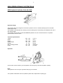
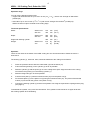
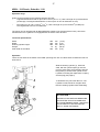
HSBL Hydraulic Cylinder, Order No. 2420
Operative Range
This cylinder has been designed to work with a pressure of max. 150 bar (2200 psi) and is used with
HSBL-Series tools.
The cylinder (1) is fastened with a bolt (2) to the tool being used. The bolts (2) are situated at the end of
the cylinder spars.
The cylinder can be driven by the NOVOPRESS hydraulic unit; we recommend the HA 1 hydraulic
system with an electric motor.
Technical specifications
Length
Width
Height
Stroke length
Weight
Max. working pressure
Power
620
140
365
120
21
150
150
mm
mm
mm
mm
kg
bar
kN
( 24.4")
(5.5")
(14.4")
(4.7")
(46 lb)
(2200 psi)
(15 tonf)
Operation
Connect the control conduit (1) of the hydraulic unit to the plug on the device (HSBL cylinder).
Note:
The hydraulic unit can only be operated if the plug is connected.
The cylinder is attached to the HA hydraulic system with a rapid-action coupling (S)
2
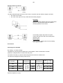
Rapid-action coupling
Coupling
Hold the coupling sleeve (KM) at the sliding
sleeve (SH) and slide onto the coupling plug (KS).
Uncoupling
Hold the coupling sleeve (KM) at the sliding
sleeve (SH) and pull off of the coupling plug (KS).
To deaerate the cylinder carry out a few idle strokes. The hydraulic unit must be on a higher level than
the cylinder during this procedure.
ATTENTION ! WHEN ATTACHING AND REMOVING THE SYSTEM TOOLS OR CARRYING
OUT MAINTENANCE WORK, UNCOUPLE THE HYDRAULIC UNIT OR DISCONNECT IT FROM THE MAINS!
Maintenance
ATTENTION !
UNCOUPLE THE HYDRAULIC UNIT OR DISCONNECT IT FROM THE MAINS BEFORE CARRYING
OUT MAINTENANCE WORK.
Every week:
– Clean and grease piston rod.
– Clean and grease fixing bolts.
Every month:
Check cylinder for leakage. If necessary, send in for repair.
3
HSBL CABLE CUTTERS, Order No. 1081
Operative range
Copper and aluminium cables of up to a diameter of 120 mm (4 3/4") can be cut with these cutters.
Technical specifications:
Width:
Length with working cylinder
Height
Weight
ATTENTION !
140
650
350
3
mm
mm
mm
kg
(5.5")
(25.6")
(13,8")
(6.6 lb)
BEFORE ATTACHING AND REMOVING THE SYSTEM TOOLS OR
CARRYING OUT MAINTENANCE WORK, UNCOUPLE THE HYDRAULIC
UNIT OR DISCONNECT IT FROM THE MAINS!
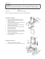
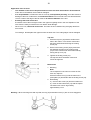
Attaching the Tools:
Place the HSBL cylinder (1) on the stand
(5). Slide the pressure plate (Order No.
1098) (11) on to the piston rod (3) and
tighten the fastening screw.
Slide the cutting edge (Order No. 1097)
(13) between the cylinder spars (4) and
fasten using the bolts (2).
Operation
The mouth can be opened by pulling out a
fixing bolt (2) and by tilting out the edge
(13). This makes it easier to put in longer
cable pieces.
The HA hydraulic unit is switched on and
off by using the foot switch on the unit.
Accessories
A specially ground edge is available for cutting reinforced cables (Order No. 4121)
Maintenance
ATTENTION !
UNCOUPLE THE HYDRAULIC UNIT OR DISCONNECT IT FROM THE MAINS BEFORE CARRYING
OUT MAINTENANCE WORK.
In case of wear or damage:
Replace or regrind cutting edge.
Regrinding
The cutting edge can be reground up to a max. of 4 mm. When the edge is reground,
care should be taken that the edge remains parallel to the edge’s back.
The cutting edge and the pressure piece of the cable cutters are subject to wear and
tear. When changing the cutting edge, the pressure piece should also be changed.
4
HSBL - 120 Cutting Tool, Order No. 2350
Operative range
You can cut the following with this tool:
– copper and aluminium rails of up to 120 x 10 mm (4 3/4" x 3/8" ) with a max. strength of 250 N/mm2
(36 250 psi).
– steel rails of up to 120 x 6 mm (4 3/4" x 1/4") with a max. strength of 370 N/mm2 (53 650 psi).
Waste consists of a piece as wide as the cutting edge.
Technical specifications
Width:
without vice
with vice
210
340
mm ( 8.3")
mm (13.4")
Depth:
without vice
with vice
200
225
mm (8")
mm (8.8")
785
mm (31")
12,0
3,0
kg
kg
Height with working cylinder
Weight:
without vice
vice
(26.4 lb)
(6.6 lb)
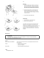
Operation
There are four holes in the bases of the HSBL cutting tool 120. Use these holes to fasten the tool to a
work bench.
The working cylinder (1), Order No. 2420, should be attached to the cutting tool as follows:
1.
Place the protective device with the cutter blade (10) into the stand (13).
2.
Pull out the fixing bolts (2) on the cylinder (1) as far as possible.
3.
Slide the cylinder (1) with the spars (4) on to the cutting tool’s spars. Align the holes on the cutting
tool with the fixing bolts (2) on the working cylinder (1).
4.
Slide the fixing bolts (2) in as far as possible.
5.
Push the base plate (11) with the knurled screws (12) onto the piston rod (3).
6.
Fix the base plate (11) to the piston rod (3) using the knurled screws (12). The points of the knurled
screws (12) must enter the groove in the piston rod (3).
7.
Connect the working cylinder (1) and the HA hydraulic unit using the rapid-action coupling and the plug
(see page 2).
To deaerate the cylinder, carry out a few idle strokes. The hydraulic unit should be on a higher level than
the working cylinder when deaerating.
5
Cutting:
1.
Lift the protective device (10).
2.
Place the rail into the cutting tool and align.
Note:
The distance between the outer edge of the cutting strip (14) and that of the cutting
edge (15) is 25 mm.
3.
Release the protective device (10).
4.
Press the foot switch on the hydraulic unit and keep pressed until cutting is completed.
ATTENTION !
BEFORE ATTACHING AND REMOVING THE SYSTEM TOOLS OR
CARRYING OUT MAINTENANCE WORK, UNCOUPLE THE HYDRAULIC
UNIT OR DISCONNECT IT FROM THE MAINS!
Accessories
Vice (100), Order No. 6950
The vice is fastened to the cutting tool with 2 screws.
It is used for holding and aligning the rail at right angles to
the cutting edge.
6
Maintenance
ATTENTION !
BEFORE ATTACHING AND REMOVING THE SYSTEM TOOLS OR CARRYING OUT MAINTENANCE WORK, UNCOUPLE THE HYDRAULIC UNIT OR DISCONNECT IT FROM THE MAINS !
After every 10 cutting operations:
Remove any shreds, chips etc. from the cutting edge (6) and cutting
strips (4).
Every week:
Clean complete cutting tool.
Any worn or damaged cutting edges or strips must be replaced immediately.
Changing the cutting edge
1.
Pull the cutting edge (6) together with the base
plate (7) and the protection device (8) out of the
stand (1) (see fig. 2).
2.
Unscrew the screws (8.9) from the protective device
(8) and remove items 8.2 and 8.3.
3.
Pull the base plate out of the protection device (8)
together with the cutting edge.
4.
Knock out the clamping sleeve (12) with a mandrel
with a diameter of 5 mm.
5.
Change the cutting edge.
6.
Assemble the base plate and the new cutting edge.
7.
Slip the protective device (8) over the base plate (7)
and onto the cutting edge (6).
8.
Use the screws (8.9) to attach items 8.2 and 8.3 to
the protective device.
Changing the cutting strips
1.
Dismantle the cutting edge (14) guides.
2.
Unscrew the bolts (10); change the cutting strips (4).
14
10
4
1
7
HSBL - 160 Cutting Tool, Order No. 7020
Operative range
You can cut the following with this tool:
–
–
copper and aluminium rails of up to 160 x 12 mm (6" x 1/2" )with a strength of max. 250 N/mm2
(36 250 psi).
steel rails of up to 160 x 6 mm (6" x 1/4 ") with a strength of max. 370 N/mm2 (53 650 psi).
Waste consists of a piece the width of the cutting edge.
Technical specifications:
Width:
without vice
with vice
Depth:
without length stop
with length stop
Height
with working cylinder
Weight
without vice
and length stop
255
375
mm (10")
mm (14.8")
310
1440
mm (12.2")
mm (56.7")
940
mm (37")
21.5
kg (47.3 lb)
vice
3,0
kg (6.6 lb)
length stop
6.0
kg (13.2 lb)
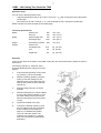
Operation
There are four holes in the bases of the HSBL cutting tool 160. Use these holes to fasten the tool to a
work bench.
The working cylinder (1), Order No. 2420,
should be attached to the cutting tool (10) as
follows:
1.
Pull out the fixing bolts (2) on the working cylinder (1) as far as possible.
2.
Slide the working cylinder (1) with the
spars (4) onto the cutting tool (10).
Align the holes on the cutting tool (10)
with the fixing bolts (2) at the working
cylinder (1).
3.
Slide the fixing bolts (2) in as far as
possible.
4.
Slide the base plate (11) onto the piston
rod (5) of the working cylinder (1). The
tip of the holding screw (12) must be
able to fit into the groove on the piston
rod (5).
5.
Tighten the holding screw (12).
6.
Connect the working cylinder (1) and
the HA hydraulic unit using the rapidaction coupling and the plug (see
page 2). To deaerate the cylinder,
carry out a few idle strokes. The
hydraulic unit should be on a higher
level than the working cylinder when
deaerating.
8
Cutting:
1.
Place the rail into the cutting tool and align.
2.
Press the foot switch on the hydraulic unit and keep pressed until cutting is completed.
Return Stroke Limitation:
The return stroke can be adjusted continuously.
Before setting the return stroke, the cutting edge must
have been lowered.
1.1
Lower the cutting edge and keep the foot
switch depressed.
1.2
Turn in the handwheel (14) of the return stroke
screw (15) against the stop in the direction of
the arrow.
1.3
Release the foot switch.
1.4
Turn out the handwheel (14) until the cutting
edge is in the desired position.
Attention!
The cutting edge must not be forced down
with the return stroke screw (15).
ATTENTION ! BEFORE ATTACHING AND REMOVING THE SYSTEM TOOLS OR CARRYING
OUT MAINTENANCE WORK, UNCOUPLE THE HYDRAULIC UNIT OR DISCONNECT IT FROM THE MAINS!
Accessories:
1). Vice (16), Order No. 7030
Description on page 5
2). Length stop (17), Order No. 6990
The length stop (17) is fastened to the
cutting tool by two screws.
Any sizes between 20 and 1600 mm
can be set with the slide (18).
9
Maintenance
ATTENTION !
BEFORE ATTACHING AND REMOVING THE SYSTEM TOOLS OR CARRYING
OUT MAINTENANCE WORK, UNCOUPLE THE HYDRAULIC UNIT OR DISCONNECT IT FROM THE MAINS !
After every 10 cutting operations:
Remove any shreds, chips etc. from the cutting edge (2) and cutting
strips (3).
Every week:
Clean complete cutting tool.
Any worn or damaged cutting edges or strips must be replaced immediately.
10
Changing the cutting edges
1. Remove the working cylinder.
2. Take out the guard plate (14).
3. Pull up the cutting edge holder with the edge
(29 and 2) and tilt out.
4. Unscrew the bolt (24) and change the edge (2).
Changing the cutting rails
1.
Unscrew the four bolts (21)
2.
Remove parts Nos. 5 and 6 also the complete protective device.
3.
Remove the cutting edge guides (8).
4.
Unscrew the bolts (23) and change the cutting strips (3).
Changing the protective window
1.
Unscrew the No. 21 bolts.
2.
Remove Nos. 5 and 6 and the complete protective device.
3.
Pull the guard plates (14) out of the protective device.
4.
Loosen the No. 25 bolts on one side.
5.
Change the window.
11
12
HSBL - Plying Iron and Angle Indicator, Order No. 1179
Operative range
This plying iron can bend:
copper and aluminium conductor rails of up to 120 x 10 mm (4 3/4" x 3/8") with a strength of up to 250
N/mm2 (36 250 psi). The maximum bending angle is 100° (degrees).
Technical specifications:
Width
Depth
Working cylinder length
Weight
210
200
625
4.4
mm (8.3")
mm (7.8")
mm (24.6")
kg (9.7 lb)
Smallest flange length (inside size) at a rail thickness of 10 mm (3/8):
At a 90° angle
At U, flange height
At Z at 90° flange height
40
80
80
mm (1.6")
mm (3.1")
mm (3.1")
Operation
1.
Connect the HSBL cylinder (1) to the hydraulic unit using the rapid-action coupling and the plug
(see page 2).
2.
Carry out a few idle strokes to deaerate it. The hydraulic unit should be on a higher level than the
working cylinder when deaerating.
Installing the tool
1.
Place the HSBL cylinder (1) on the stand (5). Put the U-shaped bottom tool (11) on to the piston rod
(3) and screw in the 2 holding screws (12) by hand.
2.
Place the angle indicator (13) with the fitting piece between the two cylinder spars (4) and slide in
as far as possible.
3.
Slide the top tool (14) between the cylinder spars (4) so that the chosen bending radius – 8 or
16 mm – faces towards the bottom tool.
4.
Fasten the top tool (14) with the fixing bolts (11).
5.
Push the angle indicator (13) back onto the top tool (14) as far as possible and tighten with the
screw (3.3).
13
6.
Aligning the bottom tool
A) At right angles to the angle indicator
Align the U-shaped bottom tool (11) at right
angles to the angle indicator (13) with the help
of a back square (20).
Screw the threaded pins (15 and 17) onto the
cylinder spars (4) so that they slide along the
whole length of the cylinder spars (4) without
any play. To test this, let the piston (3) run its
whole length backwards and forwards.
Counter the threaded pins (15 and 17) with the
nut (16).
Tighten the screws (12).
14
B) By running the machine with a piece of conductor rail, sized 120 x 10 (4 3/4" x 3/8)",
placed in it.
1.
Turn back the nuts (16) on the threaded
pins (15 and 17) by about 3 revolutions.
2.
Unsrew the threaded pins (15 and 17)
so that there is at least 2 mm of play between the cylinder spars (4) and the
threaded pins.
3.
Place a piece of conductor rail (21), e.g
120 x 10 – 200 (4 3/4" x 3/8" – 8") into the
plying iron.
4.
Bend until the safety valve in the basic
unit shuts the machine off.
Keep the foot switch pressed down and
tighten the screws (12).
Now switch off and let the piston (3)
return.
5.
Tighten the threaded pins (15 and 17) so
that they slide along the whole length of
the cylinder spars (4) without any play.
To test this let the piston (3) run its whole
length forwards and backwards.
Then counter the threaded pins (15 and
17) with the nuts (16).
Bending without the hydraulic stop
1.
Place the conductor rail on the angle indicator and hold straight.
2.
Activate the foot switch and keep pressed until the required angle has been reached.
Red scale
Black scale
for 8 mm (5/16") radius
for 16 mm (5/8") radius
3.
Release the foot switch and let the piston return.
4.
Check the angle on the angle indicator.
If the angle is not sufficient then bend further by tapping the switch lightly.
Note:
The top tool can be tilted out by removing one of the fixing bolts on the cylinder spar. This makes
removing long pieces of rail easier.
ATTENTION ! BEFORE ATTACHING AND REMOVING THE SYSTEM TOOLS OR CARRYIN
OUT MAINTENANCE WORK, UNCOUPLE THE HYDRAULIC UNIT OR DISCONNECT IT FROM THE MAINS!
15
Accessories
HAV-2 Hydraulic Stop, Order No. 1627
Operative range
A hydraulic stop (HAV-2) can be supplied as an accessory to the HSBL plying iron. The HAV-2 hydraulic
stop limits the forward and backward movements of the HSBL cylinder. The HAV-2 is of great use in
mass production. Once the angle has been set, it can be used over and over again.
Mounting the hydraulic stop
1.
The cylinder must be upright with the coupling plug facing upwards. Screw the coupling plug out of
the HSBL cylinder (2) (see page 1).
2.
Fix the valve’s body (20) to the cylinder with the banjo bolt (21).
3.
Screw the coupling plug (22) into the valve’s body (20).
4.
Remove a nut (16) from the threaded pin (17) (of the bottom tool).
Place the fastening square (24) onto the threaded pin (17) and replace the nut (16) and tighten.
5.
Loosen the banjo bolt (21) a little. Then align the valve’s body (20) so that the holes for the sliding
selector rod (25) in the fastening square (24) are in a line with those of the valve’s body (20).
Then tighten the banjo bolt (21) again.
Setting the forward movement limit
1.
Place the conductor rail on the angle indicator and hold straight.
2.
Screw the adjusting nut (23) to a distance of approximately 20 mm (3/4") from the shut-off valve.
Press the foot switch and keep pressed until the HAV-2 shuts off.
3.
Turn the adjusting nut (23) back a little and then activate the foot switch again. Keep pressed until
the HAV-2 shuts off. Then measure the angle on the bent rail. Repeat this procedure until the required angle has been achieved.
After this, counter the adjusting nut (23) with the star grip. (26)
Setting the backward movement limit
The backward movement is set by moving and tightening the control cam (27).
The movement should be set so that it is easy to remove the angled piece of material.
16
Maintenance
ATTENTION !
UNCOUPLE THE HYDRAULIC UNIT OR DISCONNECT IT FROM THE MAINS BEFORE
CARRYING OUT MAINTENANCE WORK.
After each use:
Remove any dirt, chips etc. from the HSBL plying iron and the HA2-V.
Every week:
Clean HSBL plying iron.
HA2-V
After every 3 months:
Grease thread of the HA2-V.
17
HSBL - 120 Punch, Order No. 1118
Operative range
Holes can be punched into the following with this puncher:
–
copper and aluminium rails of up to 120 x 13 mm (43/4" x 1/2") with a strength of up to 250 N/mm2
(36 250 psi). The largest hole diameter is 18 mm (at a 10 mm rail thickness 21 mm).
–
steel rails of up to 120 x 6 mm (4 3/4" x 1/4") with a strength of up to 370 N/mm2 (53 650 psi).
The largest hole size is 21 mm diameter.
The punch can be operated with all NOVOPRESS hydraulic units (except with the HA 2). We recommend that the HA 1 hydraulic unit equipped with an electric motor be used.
Technical specifications
Width
Depth:
Working cylinder height:
Weight:
Clear width of the stand:
260
200
860
15
200
mm
mm
mm
kg
mm
(10.2")
(7.8")
(33.8")
(33 lb)
(7.8")
Operation:
There are four holes in the bases of the HSBL punching tool 120. Use these holes to fasten the tool to a
work bench.
Slide the working cylinder (1), Order No.
2420, with the cylinder spars (4) onto the
punch’s press plate (10) and fasten with the
fixing bolts (2). Connect the cylinder to the
hydraulic unit using the rapid-action coupling
and the plug (see page 2).
To deaerate carry out a few idle runs. The
hydraulic unit should be on a higher level
than the working cylinder when deaerating.
ATTENTION !
BEFORE ATTACHING AND REMOVING
THE SYSTEM TOOLS OR CARRYING
OUT MAINTENANCE WORK, UNCOUPLE
THE HYDRAULIC UNIT OR DISCONNECT IT FROM THE MAINS!
18
Application rules for tools
–
The diameter of the hole to be punched must not be less than the thickness of the material.
If this rule is not followed, the tool will be damaged.
–
It is not permitted to increase the size of a hole by consequential punching, since this results in
damage of the tool. Furthermore, the minimum distance from one hole to the next and the distance from a hole to the edge of the bar must be at least the diameter of the tool.
–
Exchange the tools at due time.
Excessive wear of the tool might result in the upper tool getting stuck in the rail. Sepration of the
tools from the rail by excessive force can lead to tools damage.
–
When not in use, clean and oil the tools. The tools’ life is increased if they are lightly oiled from
time to time.
Tool storage: Do not place the upper tool into the lower tool. The cutting edges can be damaged.
Top tool
1. Place the top tool (15) with the shaft into the
hole in the column. The counter-sunk hole in
the tool’s shaft should be facing the locking
screw (16).
2. Screw in the locking screw (16) by hand and
test whether the point of the locking screw
(16) is in the counter-sunk hole of the shaft by
turning the top cool (15).
3. Tighten the locking screw (16).
The top tool has a fixed back center and
cannot be eground.
Bottom tool
1. Mounting
Note:
The receptacle for the lower tool must be free
from dirt, chips etc.
Place the bottom tool (17) into the hole on the
press plate (10) and fasten with the locking screw (18).
2. Dismantling
a) Unscrew the screw (18) from the bottom tool
b) Push out the bottom tool (17) with the ejector
The bottom tool can be reground by
approximately 2 mm.
Warning: When mounting tools with a profile, the top (15) and bottom tools (17) are not to be staggered.
19
Punching without a template
1.
Place the center-marked rail in the punch’s working area.
2.
Lift the rail and align the center mark with the back center of the top tool and hold.
3.
Straighten the rail so that it is parallel to the bottom tool’s surface. Activate the foot switch on the
hydraulic unit (punching).
4.
Release the foot switch immediately after the hole has been punched. This will prevent an
unnecessary heating of the hydraulic oil.
Holding down appliance-stripper
The punch is equipped with a holding down appliance. The holding down appliance pad also functions
as a stripper when flat bars of over 40 mm (15/8") width are being worked.
For flat bars with a width of less than 40 mm (15/8") and for lamellar copper, we offer auxiliary strippers
in addition to round tools.
Each upper tool has an auxiliary stripper of its own in a diameter range from 5 to 7,9 mm.
In a diameter range of 8 to 14 mm, (5/16" to 9/16") one auxiliary stripper is sufficient for all upper tools.
Auxiliary stripper
Order No.
ATTENTION !
Upper tool
,,D“ Order No.
Upper tool
+ stripper
Order No.
8478
8479
8399
5,0 mm
6,0 mm
6,6 mm
21990018
21990019
21990013
8481
8482
7861
8401
9,0 mm
11,0 mm
12,5 mm
14,0 mm
21990014
21990015
21990016
21990017
7862
7665
7863
7864
When subsequently ordering upper tools, it is absolutely necessary to state that
the upper tool is used in conjunction with the auxiliary stripper.
Intermediate sizes, e.g. D 5.2 mm, (3/16") on request.
Long upper tool (bare)
Key:
25 = holding down appliance
26 = auxiliary stripper
27 = cutting plate
28 = position of the workpiece after stripping
correct
wrong
The metallically bare upper tools may only be used in conjunction with the auxiliary strippers (26).
These upper tools are longer than the black standard upper tools. When using the bare upper tools
– without auxiliary strippers – the workpiece will stick to the upper tool - will not be stripped off R I S K
OF DIE BREAKAGE
Prior to punching, it is absolutely necessary to strip the material. The material thickness without
insulation may amount to max. 10 mm.
20
Standard upper tool (black)
correct
wrong
The black standard upper tools must not be used in conjuction with the auxiliary strippers, because:
— the center is not visible
— the collar of the upper tool may collide with the auxiliary stripper.7
Assembly
Place the auxiliary stripper (26) in the holding down
appliance (25) and push it firmly into position
manually (beware of the center)
The auxiliary stripper (26) must be in plane
contact with the lower side of the holding down
appliance (25).
correct
wrong
Disassembly
Pull the auxiliary stripper (26) out of the holding
down appliance (25).
Accessories
Punching with a template
No marking - no center-marking.
Templates for punching with the HSBL punch are available. These are attached to a holder
(Order No. 4109) that can be screwed onto the punch.
The width of the rails ("b") and the hole arrangement are listed in the table below.
The holes are arranged according to DIN 43 673.
Order No. of
LS Template
b - mm
Hole
arrangement
b - mm
Hole
arrangement
Sizes in
e1
e2
mm
e3
4026
40
80
20
40
40
4068
50
100
20
40
50
4070
60
120
20
40
60
Special templates on inquiry.
21
Mounting
1. Attach the holder (20), Order No. 4109, with
two cap screws (M10 x 16) (21) to the press
plate (10) in such a way that the top edges of
the holder (20) and press plate (10) are level.
2. While pressing down the catch button (22),
slide the template (23) into the holder (20)
until it reaches the bottom tooling (17) and let
it snap into place.
3. Let go of the catch button (22).
Dismantling
1. Press down the catch button (22).
2. Slide out the template (23).
The width of the rails and hole arrangement are
stated on every template. The rail (24) is to be
centered in the template as shown in pictures 1 to 4.
To get a certain hole arrangement the rail must
always be centered with the same "Y" side on the
template.
Maintenance
ATTENTION !
UNCOUPLE THE HYDRAULIC UNIT OR DISCONNECT IT FROM THE MAINS BEFORE
CARRYING OUT MAINTENANCE WORK.
Punch
Before each tool installation:
Clean the hole for the lower tool. The receptacle must be free from
dirt, shreds etc.
If dirty:
– Clean the seat for the rails.
– Clean the templates.
Every week:
– Clean and grease the HSBL punch.
Tools
See application rules.
22
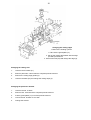
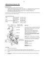
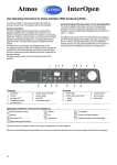
HSBL 160 Punch, Order No. 7050
Operative range
The following can be punched with this punching tool:
–
copper and aluminium rails of up to 160 x 13 mm (63/8" x 1/2") with a strength of up to 250 N/mm2
(36 250 psi). The largest hole diameter is 18 mm (at a 10 mm rail thickness 21 mm).
–
steel rails of up to 160 x 6 mm, with a strength of up to 370 N/mm2 (53 650 psi).
The maximum hole diameter is 21 mm.
The punch can be used with all NOVOPRESS hydraulic units, except with the HA2. We recommend that
the HA 1 with an electric motor be used.
Technical specifications
Width:
without stop device
with stop device
Depth:
without stop device
with stop device
Height of the working cylinder:
Weight:
without stop device
with stop devic e
440 mm
600 mm
300 mm
460 mm
900 mm
27.8 kg
38.2 kg
(17.3")
(23.6")
(11.8")
(18")
(35.4")
(61.2 lb)
(84 lb)
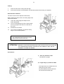
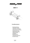
working cylinder
(Order No. 2420)
cylinder spar
fixing bolts
hand lever
stop device
accessory
punching tool
Order No. 7050)
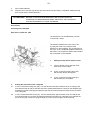
Operation
There are four holes in the bases of the HSBL
punching tool 120. Use these holes to fasten
the tool to a work bench.
Slide the 2420 working cylinder with the
cylinder spars on to the punch’s pressure
plate and fasten with the fixing bolts.
Connect the working cylinder to the hydraulic
unit using the rapid-action coupling and the
plug (see page 2).
To deaerate the cylinder carry out a few idle
runs.
The hydraulic unit should be on a higher level
than the working cylinder when deaerating.
Application rules for tools
see HSBL-120 Punch
Top tool
see HSBL-120 Punch
Bottom tool
see HSBL-120 Punch
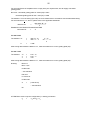
Punching
1.
WITHOUT STOP DEVICE.
1.1
Place the center-marked conductor rail in the working area of the punching tool.
1.2
Pull down the top tool with the hand lever and align the center mark with the punching tool’s backcenter.
1.3
Press the HA 1 hydraulic unit’s foot switch. Keep pressed until the punching process has been
completed.
23
2.
WITH STOP DEVICE
2.1
Slide the rail in onto the stop device and hold it there until punching is completed. Setting the stop
device (see section "STOP DEVICE")
ATTENTION ! BEFORE ATTACHING AND REMOVING THE SYSTEM TOOLS OR
CARRYING OUT MAINTENANCE WORK, UNCOUPLE THE HYDRAULIC
UNIT OR DISCONNECT IT FROM THE MAINS!
Accessories
Punching with a template
Stop device, Order No. 7190
The stop device can be adjusted by 150 mm
in the X and Y axses.
The distance between the holes can be set
by using the scale or by using the fixed
distances on the templates. The arrangement of
the holes in the completed template conforms to
DIN 43673. The respective width of the intended
bar is inscribed on the template.
1.
Setting the stop device with the scale
1.1
Turn the thumb screws (56) anti-clockwise as far as they will go.
1.2
X-axis. Loosen the locking lever (55).
Set the stop rail (30) and tighten.
1.3
Y-axis. Loosen the thumb screw (57).
Set the slide (31) and tighten.
2.
Setting the stop device with a template
2.1
X-axis. Loosen the locking lever (55). Turn the thumb screw (56) clockwise as far as it will go and
hold. Set the stop rail (30) so that the stop bolt is positioned between the holes on the template (32).
Release the thumb screw (56) and slide the stop rail (30) until the stop bolt clicks into the next hole
on the template.
2.2
Y-axis. Loosen the thumb screw (57). Turn the thumb screw (56) clockwise as far as it will go and
hold. Set the slide (31) so that it is positioned between the holes on the template (32). Release the
thumb screw (56). Continue moving the slide (31) until it clicks into place in the next hole.
24
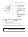
Changing the templates
1.
The templates are flat irons with holes fo
the corresponding hole arrangement.
2.
Move the slide (31) or the stop rail (30)
until it comes to rest against the stop.
3.
Lift the template (33, 34) and pull out.
4.
Take care, when inserting the template,
that the centering bolt clicks into the last
hole on the template
Mounting the stop device
1.
Move the slide (31) off the stop rail (30).
2.
Place the stop device onto the punch and fasten with the two supplied screws.
3.
Move the slide (31) onto the stop rail (30).
Maintenance
siehe HSBL-Lochwerkzeug 120
25
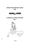
For the manufacture of templates which comply with your requirements, we will supply unmarked
guiding plates.
Ref.-Nos.: Unmarked guiding plate for X-axis (60) is 7681
Unmarked guiding plate for the Y-axis (61) is 7682
The distance "e" for the boring (D=.216") are to be determined in accordance with the attached drawing.
For the measures e1, e2, and e3, please refer to the applicable standards.
Bar width "B" - e3
---------------------2
EXAMPLE FOR TEMPLATE MANUFACTURE
Measure e4
=
Bar width "B"
=
4"
For the X-axis
The distance "X"
X
=
=
196 + B - e4
196 + 4" – 1"
=
3.196"
4" – 2"
e4= ------ = 1
2
After having determined the distance "X", mark the measures e3 on the guiding plate (62).
For the Y-axis
The distance
"Y"
Y
Y
=
=
=
5.51" - e1
5.51" - 1"
4.51"
After having determined the distance "Y", mark the measures e2 on the guiding plate (62).
Drawing:
Bmax. 6"
Bmin. 1,25"
62 DIA.236"
– 001 tolerance
DIA.216"
61 DIA.216"
62 DIA.236"
X
=
(.196"+B-e4)
– .003 tolerance
60
ATTENTION: Holes in square configuration (s. drawing) as follows:
e1
=
e4 and e2 = e3
Service
Scharnhorststraße 1
D-41460 Neuss
Postfach
101163
D-41411 Neuss
Tel.
02131 / 288-0
Federal Republic of Germany Telefax 02131 / 28855