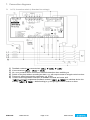
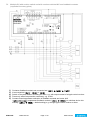
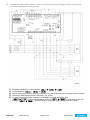
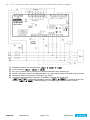
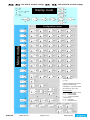
1
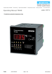
Temperature Relays and MINIKA®, Mains Monitoring, Digital Panelmeters MINIPAN®, Switching Relays and Controls Operating Instructions UFR1001E ZIEHL industrie – elektronik GmbH + Co KG Daimlerstraße 13, D – 74523 Schwäbisch Hall + 49 791 504-0, [email protected], www.ziehl.de updated: 121015 Fz from Firmware: 0-03 - NA-protection according to VDE-AR-N 4105, in-plant power generators on the low voltage grid - For use in in-plant power generators on the medium voltage grid according to BDEW - With selectable vector shift detection New, Firmware 0-03: - Standby mode - Optimized for generator operation - Automatic restarts on feedback error UFR1001E 12420-0701-01 Page 1 / 34 www.ziehl.de Table of contents 1. Application and brief description ........................................................................................................... 3 2. Summary of the functions ..................................................................................................................... 3 3. Display and controls .............................................................................................................................. 4 4. Detailed description ............................................................................................................................... 5 4.1 Description of the connections ...................................................................................................... 5 4.2 Functional characteristics .............................................................................................................. 5 5. Important information ............................................................................................................................ 6 6. Assembly ................................................................................................................................................ 7 7. Connection diagrams ............................................................................................................................. 8 8. 7.1 1x PV, 2x section switch (= Standard low voltage) ........................................................................ 8 7.2 Multiple PV with section switch and with a series-switched NC's as feedback contacts (expanded inventory plant).............................................................................................................................. 9 7.3 Multiple PV with section switch and with a parallel-switched closing contacts as feedback contacts (expanded inventory plant) ............................................................................................ 10 7.4 1x PV, 1x section switch with nc/normally closed contacts (medium voltage) .............................. 11 7.5 Generator operation, suppression of the feedback contacts (with external shut-down and mains synchronization) .......................................................................................................................... 12 Commissioning..................................................................................................................................... 13 8.1 Program setup............................................................................................................................. 13 8.2 Control chart ................................................................................................................................. 14 8.3 Description of the parameters....................................................................................................... 16 8.4 Display mode (last decimal point off) ........................................................................................... 16 8.5 Menu mode (last decimal point on) ................................................................................................. 17 8.6 Configuration mode (last decimal point flashes) .......................................................................... 17 8.7 Test mode (only activated and connected feedback contacts)..................................................... 17 8.8 Alarm counter .............................................................................................................................. 17 8.9 Cumulative alarm time (display in hours) ..................................................................................... 17 8.10 Alarm memory ............................................................................................................................. 18 8.11 Standby counter and standby time .............................................................................................. 18 8.12 Code lock ..................................................................................................................................... 19 8.13 Sealing ........................................................................................................................................ 19 8.14 Simulation ................................................................................................................................... 20 8.15 Possible indications in display ..................................................................................................... 21 9. Default settings and firmware version ................................................................................................ 22 10. Technical Data ...................................................................................................................................... 24 11. Maintenance and repair........................................................................................................................ 25 12. Troubleshooting and measures .......................................................................................................... 26 13. Construction form V6 .......................................................................................................................... 27 14. Verification of conformity ..................................................................................................................... 28 15. Adjustment values table VDE-AR-N 4105 ............................................................................................ 34 16. Adjustment values table BDEW June 2008, acc 3.2.3.3-1 ................................................................... 34 UFR1001E 12420-0701-01 Page 2 / 34 www.ziehl.de 1. Application and brief description The UFR1001E system-disconnection relay monitors voltage and frequency in three-phase current networks. In complies with the conditions for centralized NA-protection according to VDE-AR-N 4105 in inplant power generators >30kVA, for feeding into the low voltage grid and the BDEW Directive for feeding into the medium voltage grid. When using with generators, the evaluation of feedback contacts for the period of a shut-down and during the synchronization can be suppressed. The device has two channels which makes it more fail-safe. Input circuitry, evaluation and output relay are provided in duplicate. Two processors monitor each other mutually. Feedback contacts are used to monitor the functioning of both output relays and the section switch. During an alarm both channels shut down, the cause is displayed and it is reported through transistor outputs. 2. Summary of the functions Applications include monitoring the network in generating plants such as solar and wind turbine generator systems along with mains protection in combined heat and power plants, also with synchronous generators (Vector surge). The device complies with the requirements of the public utility power providers for conventional protection in low and medium voltage systems >30 kVA. Under and overvoltage monitoring 40…520 V Measurement against N and/or phase-phase Under and overfrequency monitoring 45…65 Hz Monitoring the voltage quality (10 minute average value) Vector-surge monitoring 2…20° connectible Fail-safe, with monitoring of the connected section switch (can be switched off), 2 automatic restarts on error Passive autonomous system detection in accordance with Chapter 6.5.3 and Appendix D2 Supports the mains synchronization when using generators Self-test Response time adjustable 0.05 … 130.0 s, individual setting for each limit Reset time adjustable 0 … 999 s, individual setting for each limit Reset time 5s at limit violation < 3s Presetting per VDE-AR-N 4105 Alarm counter for 100 alarms (with trip value, cause and rel. time stamp) Record of the cumulative time of alarms Standby input with counter and time memory Test button, simulation function, measurement of the shut-down times LEDs for alarm signals, measurement value allocation and relay status Sealing facility and code protection for settings, values can also be read in the sealed state Simple commissioning and programming through 4 basic programs with preset limits Message outputs for general alarm and for forwarding the cause of switching to the upstream controller (transistor, max. DC 27 V, 20 mA) Medium voltage: Per 2x2 limits for voltage and frequency: U<<, U<, U>, U>>, F<<, F<, F>, F>> Hysteresis, response and reset value individually adjustable Control voltage AC/DC 24-270 V Distributor housing V6, 6 TE 105 mm wide, front-to-back size 55 mm UFR1001E 12420-0701-01 Page 3 / 34 www.ziehl.de 3. Display and controls 1 Test button Press Output relays de-energize immediately. If Y1+Y2 are connected and the feedback signal briefly is activated, the tripping time is displayed until the next time a button is pressed 2 LEDs frequency / voltage limit value undercut / exceeded (red) 3 4 5 6 7 8 9 10 On, 8AL 8or 8AL M8 Limit value undercut / exceeded FLASHES, 8AL 8or 8AL M8 Reset delay 8dof 8 counting down LED vector surge (VSR, red) ON, 8AL 8 Threshold value for vector shift exceeded FLASHES, 8AL8 Reset delay 8dof 8 counting down LEDs relay status (yellow) OFF Relay is released ON Relay operating Digital display 4-digits (red) Depending on program, display of current voltage, frequency, vector shift, average value Displays the alarm signals, e.g. 8AL 8, 8aL M8 Displays the errors with error code e.g. 8Err98 LED Time (yellow) ON A time is displayed Last decimal point (red) OFF Display mode Illuminated Menu mode Flashes Configuration mode Set/Reset key (in display mode, normal state) Press briefly Display of next measured value / alarm counter Press for > 2 s Reset, quit error messages Displays the program, e.g. 8Pr 18 Press for > 4 s Displays the software version, e.g. 80-008 Press for > 10 s Up / Down key (in display mode, normal state) Change to the menu mode, display of alarm memory (Down) / cumulative time Press briefly of alarms, standby counter, standby time (Up), pushing Set button for ≥ 2 s resets the stored values Display of MAX (Up) / MIN (Down) - measured values, additional pushing of Set Press for > 2 s button for ≥ 2 s deletes the stored values LEDs measurement allocation (yellow) LEDs Measured value Lx and N ON Voltage value (L1 against N, L2 against N, L3 against N) Lx and Ly ON Voltage value (L1 against L2, L2 against L3, L1 against L3) Lx FLASHING quickly Vector surge (L1, L2, L3) L1 FLASHING Frequency UFR1001E 12420-0701-01 Page 4 / 34 www.ziehl.de 11 Sealable button + LED Press for > 2 s LED red LED green Lock / Unlock Settings and simulation mode are locked, While attempting to set, 8LOc 8 is displayed for 3s Setting and simulation enabled 4. Detailed description 4.1 Description of the connections Connection Description A1 and A2 Rated control supply voltage Us, see Technical Data 11, 12, 14; 21, 22, 24 Relay K1 and K2 Volt-free contact 8vsr .8 8 off.8 , no function 8vsr .8 8 on.8 , E1-E2 closed: Vector shift active but not evaluated, monitoring of feedback contacts off for use with generator (mains synchronization) E1 – E2 Enable – Input 8vsr .8 8stby.8 , E1-E2 closed: K1 and K2 off (standby), vector shift off 8vsr .8 8Y1Y2.8 , E1-E2 closed: Feedback contacts no evaluated, vector shift off, when using with generator (mains synchronization) Volt-free n/o or n/c contact, self-learning when switching on Y0, Y1, Y2 Inputs, feedback contacts Set value > turn-on time section switch under 8rel .8 8trel.8 / can switch-off if not connected or if external devices/switches can activate the section switch (8off .8) I1 Supply voltage for digital outputs, max. 27 V DC Q1…Q4 Digital output over-/undervoltage/-frequency Q5 Digital output error, in Pr 3-6 additionally the 2nd threshold value L1, L2, L3, N Phase L1, L2, L3 and neutral conductor 4.2 Functional characteristics Functional characteristics Explanation VSR display value The highest measured value is always displayed. The display value is reset to 0 by deleting the max. value and when resetting into the go (good) state. Delay Enable On time Reset time Reset Display mode 8Scn8 Runs down when starting the unit and after opening the enable input; during this time there is no evaluation of the vector shift When a reset time 8dof 8 is running, it is always counted down in the display (shortest one first) Use the Reset key or interrupt the control voltage for > 2 s (comply with reset delay) After the last measurement it switches into the scan mode; this is indicated by the display8scn 8. All measurements will now be displayed cyclically for the time set in 8dit8. MIN / MAX values All min and max values are saved zero-voltage maintained (non-volatile). Tripping time (only with feedback contacts connected) Connecting the feedback contacts enables measuring the shut-down time. After a tripping time with the test button it is displayed until a button is pressed again with a resolution of up to 1ms. Total shut-down time = Tripping time + Response time 8 dal.8 UFR1001E 12420-0701-01 Page 5 / 34 www.ziehl.de Alarm counter Cumulative alarm time 8tal .8 Standby mode 8vsr .8 8stby.8 Standby mode 8vsr .8 8y1y2.8 Automatic restart attempts After a shut-down in the simulation mode the total shut-down time is displayed until the button is pressed again) The longer time of both channels is always displayed. The unit saves max 100 alarms (cause, measurement value, at operating time). The LEDs indicate the cause; the tripping value that led to the alarm each stands in the 7-segment display. Alternately the time difference, current operating time – tripping operating time is displayed. (how long ago the alarm triggered) The cumulative alarm time TAL indicates how long the relay was switched off due to an alarm. It is recorded with a resolution of 1 minute and only when the control voltage is applied. Query: In the display mode button to 8ac .8 is displayed. 1x button = Cumulative alarm time8tal .8 If E1-E2 are closed (e.g., by ripple control receiver, timer, dimmer), Relays K1 and K2 are switched off. The number and duration of the shut-downs is recorded. Query: In the display mode button to 8ac .8 is displayed. 2x button = Standby counter 8stby.8 1x button = Standby time 8stby.8 If E1-E2 are closed, the evaluation of the feedback contacts is suppressed. That means when using generators, a section switch can be used for mains synchronization. If there is an error by the feedback contacts 8err78, 2 restart attempts are automatically performed in an interval of 10s. False triggering by undervoltage trips (e.g. during a thunderstorm) do not lead to permanent shut-down. 5. Important information ! A marked switch and a protective device must be provided in the supply line in the vicinity of the device (easily accessible) as a disconnecting element (rated current ≤ 6A). Flawless and safe operation of such a device requires proper transport and storage, professional instillation and later commissioning along with operation as intended. Only persons who are familiar with the installation, commissioning and operation of the device and who are correspondingly qualified for their job are permitted to work on the device. They must comply with the contents of the operating manual, the instructions attached to the device and the pertinent safety regulations for the erection and operation of electrical equipment. The devices are built and certified in accordance with EN 60255 and leave the factory in a safe and technically flawless condition. To maintain this condition they must comply with the safety regulations marked in the operating manual with the headline "Caution". Failure to follow the safety regulations can lead to death, bodily injury or property damage to the device itself and to other devices and equipment. If the information contained in the operating instructions/operating manual are not sufficient, please contact us directly or contact your responsible agency or representative. Instead of the industrial norms and stipulations stated in the operating manual and applicable in Europe you must comply with the valid and applicable regulations in the country of utilisation if the device is used outside of the area of application. WARNING Hazards electrical voltage! Can lead to an electric shock and burns. Disconnect and de-energize before working on the system and the device. UFR1001E 12420-0701-01 Page 6 / 34 www.ziehl.de 6. Assembly The device can be mounted: Distribution panel or control panel on 35 mm rail according to EN 60715 Comply with the maximum permissible temperature when installing in a switch cabinet. Ensure sufficient clearance to other devices or heat sources. If cooling is inhibited, e.g., through close proximity to devices with increased surface temperature or interference with the cooling-air current, the permissible ambient temperature is decreased. ! UFR1001E Caution! Before you apply mains voltage to the device, make sure that the permissible control voltage Us on the side rating plate matches the mains voltage connected to the device! 12420-0701-01 Page 7 / 34 www.ziehl.de 7. Connection diagrams 7.1 1x PV, 2x section switch (= Standard low voltage) 1) 2) 3) 4) 5) 6) Feedback contacts not connected set 8rel .8 8trel.8 8 off.8 N connected set 8Pr 18 , 8Pr 38 or 8Pr 58 Nc- or no-contacts can be connected, automatic detection when switching on Switch off the plant without recording an alarm, e.g. with output contact of a ripple control receiver Fuses only when line protection necessary, e.g. 3x16A Contact closed suppresses evaluation of feedback contacts and vector shift (8vsr .8 8 on.8 ) suppresses feedback contacts (8vsr .8 8y1y2.8 ) or switches device into standby (8vsr .8 8stby.8 = default setting) e.g. through ripple control receiver or timer UFR1001E 12420-0701-01 Page 8 / 34 www.ziehl.de 7.2 Multiple PV with section switch and with a series-switched NC's as feedback contacts (expanded inventory plant) 1) 2) 4) 5) 6) Contactor feedback contacts not connected set 8rel .8 8trel.8 8 off.8 N connected set 8Pr 18 , 8Pr 38 or 8Pr 58 Switch off the plant without recording an alarm, e.g. with output contact of a ripple control receiver Fuses only when line protection necessary, e.g. 3x16A Contact closed suppresses evaluation of feedback contacts and vector shift (8vsr .8 8 on.8 ) suppresses feedback contacts (8vsr .8 8y1y2.8 ) or switches device into standby (8vsr .8 8stby.8 = default setting) e.g. through ripple control receiver or timer UFR1001E 12420-0701-01 Page 9 / 34 www.ziehl.de 7.3 Multiple PV with section switch and with a parallel-switched closing contacts as feedback contacts (expanded inventory plant) 1) 2) 4) 5) 6) Feedback contacts not connected set 8rel .8 8trel.8 8 off.8 N connected set 8Pr 18 ,r 8Pr 38 or 8Pr 58 Switch off the plant without recording an alarm, e.g. with output contact of a ripple control receiver Fuses only when line protection necessary, e.g. 3x16A Contact closed suppresses evaluation of feedback contacts and vector shift (8vsr .8 8 on.8 ) suppresses feedback contacts (8vsr .8 8y1y2.8 ) or switches device into standby (8vsr .8 8stby.8 = default setting) e.g. through ripple control receiver or timer UFR1001E 12420-0701-01 Page 10 / 34 www.ziehl.de 7.4 1x PV, 1x section switch with nc/normally closed contacts (medium voltage) 1) 2) 3) 4) 5) 6) Feedback contacts not connected set 8rel .8 8trel.8 8 off.8 N connected set 8Pr 18 , 8Pr 38 or 8Pr 58 Nc- or no-contacts can be connected, automatic detection when switching on Switch off the plant without recording an alarm, e.g. with output contact of a ripple control receiver Fuses only when line protection necessary, e.g. 3x16A Contact closed suppresses evaluation of feedback contacts and vector shift (8vsr .8 8 on.8 ) suppresses feedback contacts (8vsr .8 8y1y2.8 ) or switches device into standby (8vsr .8 8stby.8 = default setting) e.g. through ripple control receiver or timer UFR1001E 12420-0701-01 Page 11 / 34 www.ziehl.de 7.5 Generator operation, suppression of the feedback contacts (with external shut-down and mains synchronization) 1) 2) 3) 4) 5) 6) Feedback contacts not connected set 8rel .8 8trel.8 8 off.8 N connected set 8Pr 18 , 8Pr 38 or 8Pr 58 Nc- or no-contacts can be connected, automatic detection when switching on Switch off the plant without recording an alarm, e.g. with output contact of a ripple control receiver Fuses only when line protection necessary, e.g. 3x16A Contact closed suppresses evaluation of feedback contacts and vector shift (8vsr .8 8 on.8 ) suppresses feedback contacts (8vsr .8 8y1y2.8 ) or switches device into standby (8vsr .8 8stby.8 = default setting) e.g. through ripple control receiver or timer UFR1001E 12420-0701-01 Page 12 / 34 www.ziehl.de 8. Commissioning 8.1 Program setup The suitable program must be set on the UFR1001E in accordance with the application. If the UFR1001E is sealed/locked (red LED illuminated), the sealing has to be deactivated first. Pr Connection *1 3 AC with N 2 3 AC without N 3 3 AC with N 4 3 AC without N 5 3 AC with N 6 3 AC without N * default setting Threshold values Low voltage 1x overvoltage, 1x undervoltage 1x overfrequency, 1x underfrequency 10 min average value, 1x vector shift Medium voltage 2x overvoltage, 2x undervoltage 2x overfrequency, 2x underfrequency 10min mean value, 1x vector shift Voltage 230 V 400 V 57.7 V 100 V 230 V 400 V Adjustment process: If present, remove seal (only authorised person) Apply control supply voltage at A1-A2 Slightly lift the key cover and turn 180° Actuate the small blue button by firmly pressing the button cover (LED starts flashing) until the green LED is illuminated. Sealing is deactivated Press button 1x display 8Info.8 Press button 5x display 8Pr 1.8 Set the program with the buttons Press Press button 1x display 8 no.8 button 1x display 8 yes.8 Press button Device resets and starts with the newly selected program Hint: When changing programs, all parameters of the selected program are reset to “default settings“ (see table „Default settings“). Only change the parameters after having selected the correct program. UFR1001E 12420-0701-01 Page 13 / 34 www.ziehl.de 8.2 Control chart 8Pr 18 3AC with N, acc. VDE-AR-N 4105 8Pr 28 3AC without N, acc. VDE-AR-N 4105 Display mode Menu mode Configuration mode 1) 3AC+N = 300V [ ] = Unit Up/Down simultaneously sets the value to the lowest value. Code-Reset = 2 s Set when mains are switched on. (Pin = 504) Error messages: Err4 = Tolerance Master Slave Err5 = Internal control Err6 = Communication Err7 = Contactor feedback contacts K1/K2 Err8 = Limit error Err9 = Parameter error UFR1001E 12420-0701-01 Page 14 / 34 www.ziehl.de 8Pr 38 , 8Pr 58 3AC with N, medium voltage 8Pr 48 , 8Pr 68 3AC without N, medium voltage Display mode Menu mode Configuration mode 1) 3AC+N = 300V [ ] = Unit Up/Down simultaneously sets the value to the lowest value. Code-Reset = 2 s Set when mains are switched on. (Pin = 504) Error messages: Err4 = Tolerance Master Slave Err5 = Internal control Err6 = Communication Err7 = Contactor feedback contacts K1/K2 Err8 = Limit error Err9 = Parameter error UFR1001E 12420-0701-01 Page 15 / 34 www.ziehl.de 8.3 Description of the parameters Parameters Limit value Limit value Display 8U,, 8 8U, 8 8u_ 8 8U__ 8 8Um 8 F,, , 8F, 8 , 8F_ 8 , 8F__ 8 Hysteresis 8H 8 Response time (delay Alarm) 8dAL 8 Turn-on time (delay Off) 8dOF 8 Enable time (delay On) 8dEon8 VSR 8 VSR8 delay Display 8ddi 8 Explanation Adjustment range Voltage limit value 8 15.08 … 8 3008 8 15.08 … 8 5208 Frequency limit value 845.008 … 865.008 253V (Limit) – 3V (Hysteresis) = 250V (Reset value) If the limit value is offset in Pr1 or Pr2 at 8F, 8, the hysteresis also has to be adapted so that the reset point lies at 50.05 Hz again. 8 1.08 … 8 99.08 8 0.058 … 810.008 An alarm is suppressed for the set time (seconds) 8 0.058 … 8130.08 Reset is delayed for the set time, also during voltage recovery, this time (seconds) is always counted down in the display There is no evaluation of the vector shift during this time; starts with the application of the control voltage and when opening the Enable input 81 Ph8: a vector surge on one phase leads to an alarm 83 Ph8: a vector surge on all phases simultaneously leads to an alarm 8 08 … 8 9998 8 28 … 8 208 81 Ph8 … 83 Ph8 Interval during which the display is updated in the display mode, 8 0.18 … 8 2.08 8.4 Display mode (last decimal point off) In the display mode, the UFR1001E is in its normal state; here, depending on the program, the actual voltage, the highest actual 10 minute mean value, the frequency or the vector surge is displayed. In addition, the alarm signals (e.g. 8aL 8 , 8aL m8 ) and error codes (e.g. 8err98 ) are displayed. Press briefly: Switches the measurement, alarm counter Function button Set / Reset Press for > 2 s: Resets after locked alarm (not possible if doF Reset delay is counting down) Press for > 4 s: Displays the program, e.g. 8Pr 18 Press for > 10 s: Displays the software version, e.g. 80-038 Function key Up / Down UFR1001E Press briefly: Change into the menu mode, Display alarm counter: Down = Query the memory Up = Query the cumulative alarm time Press for ≥ 2 s: Displays MAX and MIN measurements, additionally pressing the Set key for ≥ 2 s deletes the saved values 12420-0701-01 Page 16 / 34 www.ziehl.de 8.5 Menu mode (last decimal point on) The menu mode is used to select the menu items. If no key is pressed for 30 s, one automatically returns to the display mode. Press briefly: Change into the configuration mode Function button Set / Reset Press for ≥ 2 s: Returns to the display mode (the most recently set values are then applied) Function key Up / Down Press briefly: Select menu item; changes into the display mode 8.6 Configuration mode (last decimal point flashes) In the configuration mode you can set the value of a parameter. The display alternates between the parameter relation and the currently set value until one of the Up/Down buttons is pressed, which changes the value of the parameter. If no key is pressed for 2 s the display starts alternating again. If no key is pressed for 30 s (simulation mode 15 min) one automatically returns to the display mode (the most recently set value is applied during this) Press briefly: The settings are taken over; continue to next parameter. Changes into menu mode after the last parameter Function button Set / Reset Press for ≥ 2 s: Returns to the display mode (the most recently set values are then applied) Function key Press briefly/long: Value change of the parameter (slow/fast) Up / Down Hint: Simultaneously pressing the Up and Down keys resets the adjustable value to zero. If the Up or Down button is kept pressed while setting the value the change in the display is accelerated. 8.7 Test mode (only activated and connected feedback contacts) If feedback contacts of the section switch are connected to the UFR1001E and activated (value > set turnon time of section switch, e.g. 5.0s), the trip circuit can be tested by pressing the Test button. To do that, the measurement voltage has to be connected and no alarm is allowed to be present! After pressing the Test button the UFR1001E triggers. The tripping time of the internal relay + section switch are measured through the feedback contacts. After successful tripping, the tripping time of the slower switch remains shown in the display until any key is pressed. 8.8 Alarm counter The alarm counter 8ac 8 is increased by 1 with every shut-down. Up to 100 shut-downs are counted. That allows quick detection of how often the UFR1001E has shut down since the last delete of the alarm counter (see cumulative alarm time). Query the alarm counter: Change into the display mode Press the button several times until display 8acxx8 8.9 Cumulative alarm time (display in hours) The cumulative alarm time 8tal 8 indicates how long the relay was switched off due to an alarm. It is recorded with a resolution of 1 minute and only when the control voltage is applied. Query the cumulative alarm time: Change into the display mode Press the Press the button several times until display 8acxx8 button 1x display 8tal 8 / 8 x.xx8 Delete the alarm counter and cumulative alarm time (only together): Display alarm counter8acxx8 Press the Keep the UFR1001E button 1x display 8tal 8 / 8 x.xx8 button pressed for 2s until display 8tal 8 / 8 0.008 12420-0701-01 Page 17 / 34 www.ziehl.de 8.10 Alarm memory Independent of the alarm counter, the UFR1001E stores the most recent 100 shut-down causes (cause, measurement value, at operating time). Simulated alarms are also registered. The LEDs indicate the cause; the tripping value that led to the alarm each stands in the 7-segment display. Alternative to that the time is shown in hours which have passed since the last tripping (with applied control voltage). These values remain saved even after the power has been turned off. Query alarm memory: Change into the display mode Press the button several times display 8acxx8 Press the button 1x display 8 x.xx8 / 8 x.xx8 (tripping value or error no. / time that has passed in hours) Press the button 1x, go to next alarm The alarm memory is only deleted during a program change. 8.11 Standby counter and standby time The standby counter 8stby8, is increased by 1 with every standby shut-down. Up to 9999 shut-downs are counted. That lets the UFR1001E quickly detect how often, e.g., shut-down was performed through a ripple control receiver. Query the standby counter: Change into the display mode Press the button several times until display 8acxx8 Press the button 2x display 8stby8 / 8xxxx8 The standby time 8stby8 indicates how long the relay was switched off by the standby mode. It is recorded with a resolution of 1 minute and only when the control voltage is applied and if no alarm is present. Query the standby time: Change into the display mode Press the Press the button several times until display 8acxx8 button 3x display 8stby8 / 8 x.xx8 (Time LED is illuminated) Delete the standby counter and standby time (only together): Display alarm counter8acxx8 Press the Keep the UFR1001E button 2x display 8stby8 / 8xxxx8 button pressed for 2s until display 8stby8 / 8 12420-0701-01 Page 18 / 34 08 www.ziehl.de 8.12 Code lock You can protect the set parameters by enabling the code lock here. The device acknowledges an incorrect entry with 8err8 (flashes three times). Adjustment process: Select the menu item with the Press the buttons until display 8Code.8 button 1x display 8Pin 8 / 8 Set the saved pin code with the Press the 08 buttons (default setting is 8 5048 ) button 1x display 8Code8 / 8off 8 Use the buttons to set the desired code lock: o 8 off8 off, all parameters can be changed o 8 On8 on, no parameters can be changed Press the Use the button 1x display 8Pin 8 / 8 5048 buttons to set the new, desired pin code (caution: write down the pin code) Press the button 1x Code lock on, display 8 on8 flashes three times Code lock off, display 8 off 8 flashes three times Return to menu mode, menu item code lock If there are any problems with the code lock (pin forgotten), the lock can be switched off and the pin can be reset to 504 by keeping the Set key pressed while switching on the mains until 8Code8 / 8 off8 appears in the display. 8.13 Sealing All the settings and the simulation mode can be locked. If the LED is illuminated, the UFR1001E is locked. If an attempt is made to change a setting in the locked state, for 3s the display shows 8LOc 8. Adjustment procedure Sealing/Lock ON (OFF): If present, remove seal (only authorised person) Apply control supply voltage at A1-A2 Slightly lift the key cover and turn 180° Actuate the small blue button by pressing the button cover very firmly (LED starts flashing) until the green LED UFR1001E 12420-0701-01 is illuminated. Page 19 / 34 www.ziehl.de 8.14 Simulation Here, the voltage, frequency or a vector surge can be simulated and the setting can be tested. All 3 phases plus the 10 minute mean value are always simulated. All functions of the device operate as if this value is actually being measured. Alarm and error messages are only indicated with the LEDs and not in the display. The set values are simulated until the menu item si . is exited with the or button. If the UFR1001E is sealed/locked, simulation is not possible. If the section switch feedback contacts are connected to the UFR1001E and enabled, (set value > sectionswitch turn-on time under 8trel.8), after a shut-down, the tripping time (dAL + time of slowest section switch) is displayed. Adjustment process: Select the menu item with the Press the buttons until display 8si button 1x display 8si 8 / 8u .8 8 Use the buttons to set the measurement factor for simulation: o 8u 8 Voltage + 10min mean value (frequency = last simulated value) o 8f 8 Frequency (voltage = last simulated value) o 8vsr 8 Vector shift Press the Use the button 1x display 8 2308 (selected measurement factor is simulated) buttons to set the desired value After exiting the Simulation menu item with the buttons, the unit switches over to monitoring the limits. The unit automatically returns to the display mode if no button is pressed for 15 minutes. Hint: A limit value should be tested that is higher than the set 10min mean value. If the 10min mean value has to be temporarily switched off, set (8Um .8 8 off.8 since otherwise it will trip first. The same applies, for example, for U, , during a simulation of U,, in Pr3 and Pr4. (Medium voltage) UFR1001E 12420-0701-01 Page 20 / 34 www.ziehl.de 8.15 Possible indications in display Display mode 8 AL 8 , 8Am 8 Alarm , Alarm 10min mean value 8Err48 …8err98 Error messages (see 11. Error messages and measures) 8Ac Alarm counter, cumulative alarm time 8 , 8tal 8 8Scn 8 , 8 M 8 Scan mode, 10min mean value Menu mode / configuration mode U,, , 8U, 8 , Voltage limit value 8u__ 8 , 8U_ 8 UM 8 Limit value 10min mean value H,, , 8H, 8H__ 8 , 8H_ 8 , 8 , 8HM 8 Hysteresis (if a limit value is changed, the reset value also shifts; that means it might be necessary to adapt it) F,, , 8F, 8 , 8F__ 8 , 8F_ 8 Frequency limit value 8dal 8 Response time 8dof 8 Reset time; is always counted down in the display 8vsr 8 Vector surge 8stby8 Standby mode, standby-time, standby-counter 8y1y28 Evaluation of the feedback contacts is suppressed when E1-E2 are closed 8Deon8 Delay Enable On, suppression time when switching on and after opening the enable input 81 ph 8 , 83 ph 8 Single phase, three-phase vector shift evaluation 8rel 8 Relay ttrel8 Section switch turn-on time, 8 off8 no feedback contacts 8ddi 8 Delay display, to calm down the display Display duration scan mode (each measurement is displayed for this duration) Dit 8 8Si 8 Simulation F , 8U Code , 8Plo 8 , 8vsr8 8 8Pin 8 Frequency, voltage Code lock / sealing, vector shift Pin code (default 504) Info8 Device information, program change Fnr 8 , 8snr 8 Firmware version, serial number h Operating hours 8 Err 8 , 8del 8 8yes 8 , 8no Pr 8 8 8 Yes, no query for acknowledgement Program on8 , 8 oFF8 UFR1001E Error counter, delete error counter 12420-0701-01 On, Off Page 21 / 34 www.ziehl.de 9. Default settings and firmware version When changing programs, all parameters are reset to the default settings. Users data Default settings Menu item U,, U, U_ U__ F,, F, Medium voltage 3AC+N 3AC 3AC+N 57.7V 100 V 230V Pr3 Pr4 Pr5 on on on 3AC 400V Pr6 on u,, Alarm on/off u,, Overvoltage V - - 66.4 115 264 458 H,, Hysteresis V - - 1.0 1.0 3.0 3.0 dal Response time s - - 0.10 0.10 0.10 0.10 s - - 60 60 60 60 on on On on on on dof OFF-delay u, Alarm on/off u, Overvoltage V 264 458 62.3 108 249 430 H, V 5.0 5.0 1.0 1.0 3.0 3.0 s 0.10 0.10 60.00 60.00 60.00 60.00 s 60 60 60 60 60 60 on on Off Off off Off dal UM Low voltage 3AC+N 3AC 230V 400V Pr2 Pr1 * - Parameter / Unit Hysteresis Response time dof OFF-delay UM Alarm on/off UM Overvoltage V 253 438 253 438 253 438 HM Hysteresis V 3.0 3.0 3.0 3.0 3.0 3.0 dal Response time s 0.10 0.10 0.10 0.10 0.10 0.10 s 60 60 60 60 60 60 on on On On on on dof OFF-delay u_ Alarm on/off u_ Undervoltage V 184 318 46.2 80.0 184 318 H_ Hysteresis V 5.0 5.0 1.0 1.0 3.0 3.0 dal Response time s 0.10 0.10 2.70 2.70 2.70 2.70 s 60 60 60 60 60 60 - - Off Off off Off dof OFF-delay u__ Alarm on/off u__ Undervoltage V - - 26.0 45.0 104 180 H__ Hysteresis V - - 1.0 1.0 2.0 2.0 dal Response time s - - 0.30 0.30 0.30 0.30 s - - 60 60 60 60 - - off Off off Off dof OFF-delay F,, Alarm on/off F,, Overfrequency Hz - - 51.50 51.50 51.50 51.50 H,, Hysteresis Hz - - 1.45 1.45 1.45 1.45 dal Response time s - - 0.10 0.10 0.10 0.10 s - - 60 60 60 60 on on on on on on dof OFF-delay F, Alarm on/off F, Overfrequency Hz 51.50 51.50 51.50 51.50 51.50 51.50 H, Hysteresis Hz 1.45 1.45 1.45 1.45 1.45 1.45 dal Response time s 0.10 0.10 0.10 0.10 0.10 0.10 s 60 60 60 60 60 60 dof UFR1001E OFF-delay 12420-0701-01 Page 22 / 34 www.ziehl.de Default settings Low voltage Menu item F_ F__ vsr Parameter / Unit ddi Si CodE Info Pr1 * on 3AC 400V Pr2 3AC+N 3AC 57.7V 100 V Pr3 Pr4 3AC+ N 230V Pr5 3AC 400V Pr6 on on on on on 47.50 47.50 47.50 47.50 47.50 47.50 Hz 1.00 1.00 1.00 1.00 1.00 1.00 s 0.10 0.10 0.10 0.10 0.10 0.10 s 60 60 60 60 60 60 - - off off off off F_ Alarm on/off F_ Underfrequency Hz H_ Hysteresis dal Response time dof OFF-delay F__ Alarm on/off F__ Underfrequency Hz - - 47.50 47.50 47.50 47.50 H__ Hysteresis Hz - - 1.00 1.00 1.00 1.00 dal Response time s - - 0.10 0.10 0.10 0.10 s - - 60 60 60 60 stby stby stby stby stby stby dof OFF-delay vsr Alarm on/off vsr Vector shift ° 10.0 10.0 10.0 10.0 10.0 10.0 dof OFF-delay s 3 3 3 3 3 3 dEon Suppression time s 2 2 3 3 3 3 3ph 3ph 3ph 3ph 3ph 3ph s 5.0 5.0 off off off off s 0.5 0.5 0.5 0.5 0.5 0.5 vsr rEL 3AC+N 230V Medium voltage Number of phases trEL Response time Y1,Y2 ddi Display delay dit Display duration SCn s 3.5 3.5 3.5 3.5 3.5 3.5 U Voltage V 230 400 57.7 100 230 400 F Frequency Hz 50.00 50.00 50.00 50.00 50.00 50.00 vsr Vector shift ° 0.0 0.0 0.0 0.0 0.0 0.0 pin Pincode 504 504 504 504 504 504 fnr Firmware version 0-03 0-03 0-03 0-03 0-03 0-03 snr Serial number xxxxx xxxxx xxxxx xxxxx xxxxx xxxxx h Operating hours xxxxx xxxxx xxxxx xxxxx xxxxx xxxxx err Error counter xxx xxx xxx xxx xxx xxx Pr Program 1 2 3 4 5 6 h * default setting Display of the program: 8Info8 8Pr 8 or when switching on Display of the firmware version: 8Info8 8fnr 8 UFR1001E 12420-0701-01 Page 23 / 34 www.ziehl.de Users data 10. Technical Data Control voltage Us: Rated connection Output relay: Switching voltage Conventional thermal current Ith Inrush current (at 10 % ED) Nominal operating current Ie (AC 15) Recommended series fuse Contact service life, mech. Contact service life, electr. Voltage measurement: Measurement voltage phase – phase Adjustment range phase – phase Measurement voltage phase – N Adjustment range phase – N Measurement principle Hysteresis Measurement error (with N) Measurement error (without N) Display accuracy Measurement function Response time Reset time AC/DC 24-270 V, 0/40...70 Hz, < 5 VA DC: 20.4...297 V, AC: 20.4...297 V 2 x change-over contact Max. AC 440 V 6A 25 A max. 4 s / 50 A max. 1 s 6 A AC 250 V gG/gL 6 A 30 x 106 switching cycles 1 x 10⁶ operating cycles at AC 250 V / 6 A 2 x 10⁵ operating cycles at AC 250 V / 10 A cos φ 0.6 AC 15…530 V (< 5 V: 0 is displayed) AC 15…520 V AC 10…310 V (< 5 V: 0 is displayed) AC 15…300 V Real root mean square measurement both half waves Adjustable 1.0…99.9 V ± 0.6 % of the measurement value ± 0.8 % of the measurement value >100V: -1 digit (res. 1 V) <100V: -1 digit (res. 0.1V) 3-phase with/without N Adjustable 0.05 (±15ms)…130.0 s Adjustable 0(>200ms) … 999 s Frequency measurement Frequency range Adjustment range Hysteresis Measurement accuracy Response time Reset time 40…70 Hz 45.00…65.00 Hz 0.05…10.00 Hz ± 0.04Hz ± 1 digit Adjustable 0.05 (±15ms)…130.0 s Adjustable 0 (>200ms) … 999 s Vector surge Measurement range Adjustment range Response time Reset time Delay at Us on 0…45.0° 2.0…20.0° < 50 ms Adjustable 3…240 s Adjustable 2…20 s Digital outputs (galvanic isolated) Switching voltage I1 Current Q1…Q5 DC 4.5…27 V Max 20 mA / output Contactor feedback inputs Voltage Y0 – Y1/2 DC 15…35 V Contactor response time (section switch) Adjustable 0.5...99.0 s UFR1001E 12420-0701-01 Page 24 / 34 www.ziehl.de Test conditions EN 60255 Rated impulse withstand voltage 4000 V Surge category III Pollution level 2 Rated insulation voltage Ui 300 V Insulation group II Operating time 100 % Permissible ambient temperature -20 °C... +55 °C EN 60 068-2-1 dry heat EMC - noise immunity EN 61000-6-2 EMC - noise emission EN 61000-6-3 Housing: Construction form Front-to-back size Dimensions (W x H x D) Wiring connection single strand Finely stranded with wire end ferrule Protection class, housing Protection class, terminals Weight: V6 55 mm 90 x 105 x 69 mm each 1 x 4mm2 each 1 x 2.5mm2 IP 30 IP 20 Mounting snap-on fastening on 35 mm mounting rail acc EN 60 715 or with M4 screwed attachment (additional bar not included in the scope of delivery) approx. 250 g We reserve the right to make technical changes 11. Maintenance and repair The UFR1001E is maintenance-free. Periodically test for proper functioning. UFR1001E 12420-0701-01 Page 25 / 34 www.ziehl.de 12. Troubleshooting and measures Error Cause Remedy 8EEEE8 or 8-EEE8 appears in the display Measurement is above/below range Measured voltage, frequency or the vector surge is too large or too small; comply with measurement range 8Err48 appears in the display Tolerance error Internal measurement value deviation of both channels, do a reset interrupt control voltage for >5s 8Err58 appears in the display Error internal interface Reset interrupt control voltage for >5s 8Err68 appears in the display Communication error, internal interface Reset interrupt control voltage for >5s Feedback contacts not connected Set - 8rel .8 8trel.8 8 off8 Feedback contacts not connected - Check for correct connection - Set turn-on time of section switch under 8trel.8 - Do a reset interrupt control voltage for >5s Upper threshold value must be higher than the lower threshold value, check the threshold values 8Err78 also appears in the display after 2 automatic reconnection attempts, LED K1 and / or K2 illuminated Feedback contacts connected 8Err88 appears in the display Hysteresis error 8Err98 appears in the display Parameter error Reset to factory settings, see “Program setup” A time expires in the display Always when an OFF-delay time 8dof 8 is running, it is counted down in the display (shortest one first) Wait until the time has expired (depending on the setting, several times may elapse one after the other) Code lock / Sealing activated If there are any problems with the code lock (pin forgotten), the lock can be switched off and the pin can be reset to 504 by keeping the Set key pressed while switching on the mains until 8Code8 / 8 off8 appears in the display. Pr selected with N, but N not connected Select Pr without N or connect N Seal is active See Sealing Code lock is active See „Code lock“ Standby mode, E1-E2 closed Check parameter 8 vsr.8 Device cannot be configured / only the limits can be configured Implausible voltage values 8Loc 8 appears in the display 8Code8 appears in the display 8stby8 appears in the display UFR1001E 12420-0701-01 Page 26 / 34 www.ziehl.de 2 1 13. Construction form V6 3 Dimensions in mm 69 58 70 48 Option 16,5 116 98 (90) 45 61,8 5 4 3 1 6 2 3 7 105 1 2 3 4 5 6 7 UFR1001E Oberteil / cover Unterteil / base Riegel / bar for snap mounting Sealing max. Ø 1.8 mm Frontplatteneinsatz / front panel Kennzeichen für unten / position downward Bar for wall attachment with screws. Riegelbohrung Ø 4,2 mm / Bolt hole for fixing to wall with screws, Ø 4.2 mm. 12420-0701-01 Page 27 / 34 www.ziehl.de 14. Verification of conformity UFR1001E 12420-0701-01 Page 28 / 34 www.ziehl.de UFR1001E 12420-0701-01 Page 29 / 34 www.ziehl.de UFR1001E 12420-0701-01 Page 30 / 34 www.ziehl.de UFR1001E 12420-0701-01 Page 31 / 34 www.ziehl.de UFR1001E 12420-0701-01 Page 32 / 34 www.ziehl.de UFR1001E 12420-0701-01 Page 33 / 34 www.ziehl.de 15. Adjustment values table VDE-AR-N 4105 AR 4105 ZIEHL in * Un in % Un Adjustment value Tripping time dAL OFF-delay time doF Voltage decrease protection U< U_ 0.8 * Un 80 % Un 184 V 100 ms 60 s Voltage increase protection (10-minutes mean value) U> UM 1.1 * Un 110% Un 253V 100 ms 60 s Voltage increase protection U>> U, 1.15 * Un 115% Un 264V 100 ms 60 s Frequency decrease protection f< F_ 47.5Hz 100 ms 60 s Frequency increase protection f> F, 51.5Hz 100 ms 60 Protective function 16. Adjustment values table BDEW June 2008, acc 3.2.3.3-1 Function Adjustment range of the protective relay Default settings Voltage increase protection U>> 1.00 – 1.30 Un 1.15 Un 100 ms Voltage increase protection U> 1.00 – 1.30 Un 1.08 Un 60 s Voltage decrease protection U< 0.15 – 1.00 Un 0.80 Un 2.7 s Voltage decrease protection U<< * 0.15 – 1.00 Un 0.45 Un 300 ms Frequency increase protection f> 50.0 – 65.0 Hz 51.5Hz 100 ms Frequency decrease protection f< 45.0 – 50.0 Hz 47.5Hz 100 ms * Not enabled in as delivered condition UFR1001E 12420-0701-01 Page 34 / 34 www.ziehl.de