1
Please keep carefuly!
santos (F) 370 DC
Standard
Operating Instructions
Mechanical Ventilation Heat Recovery Unit
Status: 11.2012
Components
suitable for
Passive
House
Dr. Wolfgang Feist
santos 370 DC
Paul Wärmerückgewinnung GmbH
August-Horch-Straße 7
08141 Reinsdorf
Germany
Tel.: +49(0)375 - 303505 - 0
Fax: +49(0)375 - 303505 - 55
All rights reserved.
This operating manual has been produced with the greatest care and attention. Nevertheless, the publisher
accepts no liability for damage resulting from missing or incorrect information in this operating manual.
EN
Table of Contents
FOREWORD ........................................................................................................................................................... 1
1
INTRODUCTION ............................................................................................................................................. 1
1.1
CE Symbol ................................................................................................................ 1
1.2 Guarantee and Liability ................................................................................................ 1
1.2.1 General Information .................................................................................................................. 1
1.2.2 Guarantee Terms and Conditions ............................................................................................ 1
1.2.3 Liability ...................................................................................................................................... 1
1.3
2
Safety ................................................................................................................................................... 2
1.3.1 Safety Regulations ................................................................................................................... 2
1.3.2 Safety Provisions and Safety Measures .................................................................................. 2
1.3.3 Symbols Used........................................................................................................................... 2
INSTRUCTIONS FOR THE USER .................................................................................................................. 3
2.1
Definition of Terms .............................................................................................................................. 3
2.1.1 Balanced Ventilation (controlled residential ventilation) ......................................................... 3
2.1.2 Heat Recovery .......................................................................................................................... 3
2.1.3 Bypass for Free Cooling ........................................................................................................... 3
2.1.4 Frost Protection ........................................................................................................................ 3
2.1.5 Fireplace Control ...................................................................................................................... 3
2.1.6 Enthalpy Exchanger ................................................................................................................ 3
2.2
Available Operating Aids .................................................................................................................... 4
2.2.1 Display on Unit ......................................................................................................................... 4
2.2.2 3-Position Switch ..................................................................................................................... 4
2.2.3 Forced Ventilation with Bathroom Switch ............................................................................... 5
2.3
P Menus for the User .......................................................................................................................... 5
2.4.
Service by the User ........................................................................................................................... 7
2.4.1 Cleaning or Replacing Filters ................................................................................................... 7
2.4.2 Cleaning Valves (in the home) .................................................................................................. 7
2.5
Malfunctions ........................................................................................................................................ 7
2.5.1 What to Do in the Event of a Malfunction? ............................................................................. 8
2.6.
Disposal .............................................................................................................................................. 8
III
EN
3.
INFORMATION FOR THE INSTALLER ........................................................................................................... 9
3.1
Configuring the santos ....................................................................................................................... 9
3.2
Technical Specifications................................................................................................................... 10
3.3
Dimension Sketch ............................................................................................................................. 12
3.4
Conditions for Installation ................................................................................................................ 13
3.5
Installing the santos ....................................................................................................................... 13
3.5.1 Transport and Unpacking ....................................................................................................... 13
3.5.2 Checking the Scope of Supply .............................................................................................. 13
3.6
Mounting the santos ....................................................................................................................... 13
3.6.1 Wall mounting ......................................................................................................................... 13
3.6.2 Connecting the Air Ducts ....................................................................................................... 13
3.6.3 Connecting the Condensation Drain ..................................................................................... 14
3.7
Commissioning the santos .............................................................................................................. 15
3.7.1 Display on Unit ....................................................................................................................... 15
3.7.2 P Menus for the Installer ........................................................................................................ 17
3.8.
Setting Air Specifications ............................................................................................................... 19
3.9.
Maintenance Information for the Installer ...................................................................................... 20
3.9.1 Inspecting the Heat Exchanger and Fans ............................................................................. 20
3.10
Malfunctions ..................................................................................................................................... 22
3.10.1 Malfunction Messages Displayed .......................................................................................... 22
3.10.2 Overview of Malfunctions....................................................................................................... 23
3.10.3 Malfunctions (or Problems) not Displayed ............................................................................ 26
3.12
Wiring Diagram: santos 370 DC Basic – LEFT-HAND Version ...................................................... 27
3.13
Wiring Diagram: santos 370 DC Basic – RIGHT-HAND Version .................................................... 28
CE DECLARATION OF CONFORMITY ............................................................................................. 29
Part B Annexes .................................................................................................................................. 30
Checklist A Maintenance Work by the Owner/User ...................................................................... 31
Checklist B for Qualified Personnel ................................................................................................ 32
Air Volume Protocol .......................................................................................................................... 33
Annexes:
Appendix 1 Terminal connection plan santos (F) 370 DC left hand side
Appendix 2 Terminal connection plan santos (F) 370 DC right hand side
Technical data santos (F) 370 DC
Checklist A Maintenance work by the Owner / User
Checklist B for qualified personal
Air volume protocol
Checklist Commissioning and handover
CE Declaration of conformity santos 370 DC - Serie
EN
IV
Foreword
In addition to this general chapter, this operating
manual consists of:
• A section for the user,
• A section for the installer.
Please read this operating manual carefully
before using the unit.
- User
Chapters 1 and 2.
- Installer
Chapters 1 and 3.
This operating manual contains all the information
required to safely and properly install, operate and
maintain the santos 370 DC Basic. In addition, it
should serve you as a reference manual to enable
you to carry out service work safely and responsibly. Due to continuing further development of the
unit it is possible that your santos 370 DC Basic
may differ slightly from the unit described in this
manual.
This manual has been produced with the
greatestSFlb care and attention. However,
we do not accept legal liability for the contents. Furthermore, the company reserves
the right to change the contents of this
SFIboperating manual at any time without
prior SFlbnotification.
1
Introduction
CE Symbol
The unit carries the designation santos 370 DC Basic, hereafter referred to as santos.
The santos is a balanced ventilation system with
heat recovery functionality that provides healthy,
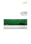
balanced and energy-saving ventilation in residential premises. The santos identification plate is depicted below.
Type
Voltage
Product code
1.2.1 General Information
The relevant terms and conditions of sales and
guarantee for metal, plastic and technical works
submitted to the District Court in Den Haag, Netherlands, on 19th October 1998 shall apply.
1.2.2 Guarantee Terms and Conditions
The manufacturer guarantees the santos for a period of 24 months following installation or up to a
maximum of 30 months following the date of manufacture of the santos. Claims under guarantee can
be asserted only for defective material and/or workmanship that become apparent during the period
of guarantee. In the event of a guarantee claim,
the santos must not be dismantled without the
prior written permission of the manufacturer. The
manufacturer guarantees spare parts only if these
have been replaced and installed by an installer approved by the manufacturer.
The guarantee will be null and void
if:
•
•
•
•
This chapter contains general information on the santos 370 DC Basic.
1.1
1.2. Guarantee and Liability
Hertz
The guarantee period has expired;
The unit is operated without filters;
Parts not supplied by the manufacturer are installed;
Unauthorised changes or modifications are
made to the unit.
1.2.3 Liability
The santos has been developed and manufactured
for use in so-called "balanced ventilation systems".
Any other use is considered 'improper use' that can
result in damage to the santos or personal injury for
which the manufacturer accepts no liability.
The manufacturer accepts no liability for damage or
injury resulting from the following:
•
Failure to observe the safety, operating and
maintenance instructions contained in this operating manual;
• Installation of spare parts not supplied or approved by the manufacturer.
Responsibility for the use of such spare parts
lies solely with the installer;
• Normal wear and tear.
Phase
Current
Power
Condensor
Protecion class
Insulation class
Serial number
1
EN
1.3
Safety
1.3.1 Safety Regulations
Observe the safety regulations given in this operating manual at all times. Failure to observe the safety
regulations, warnings, comments and instructions
can result in personal injury or damage to the santos.
•
•
•
•
•
•
•
•
EN
Unless clearly stated otherwise in this operating manual, the santos must be installed, connected, commissioned and maintained by an
authorised installer only;
The santos must be installed in compliance
with the general building, safety and installation
regulations that apply to the place of installation
issued by the respective local authority, water
and electricity utility and other official regulations and guidelines;
Observe the safety regulations, warnings, comments and instructions given in this operating
manual at all times;
Keep this operating manual with the santos
throughout its service life;
Closely observe the instructions regarding the
regular replacement of filters and cleaning of
supply and exhaust air valves;
The specifications stated in this document must
not be altered;
Do not make any modifications to the santos;
To ensure that the unit is inspected at regular intervals we recommend that the user concludes
a service contract. Your supplier can provide
you with the addresses of authorised installers
in your vicinity.
2
1.3.2 Safety Provisions and Safety Measures
•
•
The santos cannot be opened without the use
of tools.
It must not be possible to touch the fans with
your hand. For that reason air ducts must be
connected to the santos. The minimum duct
length is 900 mm.
1.3.3 Symbols Used
The following symbols are used in this operating
manual:
Caution!
Risk of:
- Damage to the unit;
- Operational reliability of the unit will be
adversely affected if the instructions are
not correctly observed.
Risk of physical injury to the user or the installer.
2 Instructions for the User
This chapter describes how you should use the santos.
Congratulations, you are now the owner of a santos 370 DC Basic,
a heat recovery unit built by Paul
Wärmerückgewinnung GmbH.
We wish you every comfort.
2.1
Definition of Terms
The santos unit offers the following functions:
• Balanced ventilation;
• Heat recovery;
• Bypass for free cooling;
• Frost protection;
• Chimney sweep control system;
• Enthalpy exchanger (optional).
These terms/properties are described briefly in
more detail in the following sections.
2.1.1 Balanced Ventilation (controlled
residential ventilation)
The santos unit has been designed to provide balanced ventilation. Balanced ventilation systems
extract stale air contaminated with smells from the
kitchen, bathroom, WC(s) and, if necessary, a utility room and introduce an equal volume of fresh air
to the living room, bedroom and children's room. A
gap below the doors guarantees a good and balanced air circulation in the home.
Ensure that these gaps are not blocked by,
for example, rubber draught excluders or
high-pile carpets. This would prevent the
system from operating at an optimum.
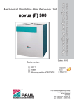
A balanced ventilation system generally consists of
the following elements:
• santos (A);
• Duct system for the intake of outside air (B)
and the discharge of indoor air (C);
• Air supply valves in the living rooms and bedrooms (D);
• Exhaust air valves in the kitchen, bathroom,
toilet and, if required, the utility room (E).
In addition to a well-balanced ratio between supply
and exhaust air volumes the santos unit also offers
the benefit of heat recovery. Heat recovery removes
the heat from stale exhaust air and transfers it to the
fresh, mostly cooler intake air.
2.1.3 Bypass for Free Cooling
The bypass is used most of all on warmer days in
the summer months to allow in the cool night air.
The bypass functions automatically. All that is required is to set the comfort temperature level.
2.1.4 Frost Protection
The santos is equipped with frost protection. Frost
protection is an automatic safeguard function that
drastically sinks (or even interrupts) the intake of
outside air in the santos when there is a risk of frost.
The risk of freezing exists in the winter months with
moderate to heavy frost.
2.1.5 Fireplace Control
A suitable safety device or integral system safeguard is required when jointly operating non roomsealed fireplaces and ventilation systems if there is
a risk that during operations a dangerous negative
pressure can be created in the room in which the
fireplace is located.
The santos is equipped with fireplace control; however, this must be activated by the installer.
Fireplace control does not replace a safety
device designed to monitor the difference
in pressure; it is a technical precondition for
operating the unit when fireplaces are being
used at the same time.
Once the fireplace control is activated the
supply air and exhaust air fans cannot be
deactivated manually.
2.1.6 Enthalpy Exchanger (optional)
C
B
2.1.2 Heat Recovery
The ventilation system can also optionally be
equipped with an enthalpy exchanger. An enthalpy
exchanger helps to regulate the humidity level in the
home. As well as recovering the heat the enthalpy
exchanger also recovers the moisture. The moisture
from the extracted air is transferred to the intake air
being introduced. Moreover, enthalpy exchangers
are less susceptible to frost.
A
D
D
E
D
E
D
E
3
EN
2.2
Available Operating Aids
These operating aids are described briefly in more
detail in the following sections.
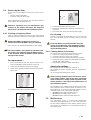
2.2.1 Display on Unit
Settings can be set via the digital display and operating panel on the santos unit.
▼(10 x or
hold down)
20
Select 20
6
OK
P22
Current value is 20
7
MENU
P2
5
The santos can be equipped with the following operating aids:
• Display on unit;
• 3-position switch;
• Bathroom switch (optional) to temporarily set
the highest ventilation level.
8
MENU
1
Fan steps
Settings can only be made in the P2 menus.
The other P menus (P1 and P9) are readonly menus.
End (read) menu
•
Press "MENU" (instead of "OK").
The display cannot be used to set the
santos ventilation levels. The arrow keys
can only be used to set the additional programmes.
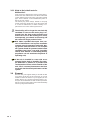
2.2.2 3-Position Switch
Call
MENU
up
A 3-position switch is used to set the ventilation
levels of the santos. One or more 3-position switches can be installed in a home (for example, in the
kitchen).
menu
Up
OK
OK
Down
Supply air off
(LED green)
Exhaust air and
supply air on
(LED green)
When several position switches are installed
in the home the santos operates according
to the highest ventilation level set, unless a
different level is set in the automatic software
control.
Comfort temperature
Setting the ventilation level with the
3-position switch
Display read-out:
A
No ventilation
1
The 3-position switch enables you to set three ventilation levels.
Ventilation level low
2
Ventilation level medium
3
Ventilation level high
X X
Menu display
X X
Malfunction code (flashes)
•
Bypass
Accessing the menus
Sequence
Operating
keys
Display
Description
1
MENU
P2
Time delay values
2
▲
P9
Status display
3
▲
P1
Status display
Sequence
Operating
keys
Display
Description
1
MENU
P2
Time delay values
2
OK
P21
Activation delay value
3
▲
P22
Select 22
4
OK
30
Current setting
4
Position 1 J
•
Position 2 J
•
Position 3 J
Low.SFlb- Use for low ventilation requirements.
Normal.SFlb- Use for normal
ventilation requirements.
High.
- Use this level when cooking,
showering and when high-level
ventilation is desired.
1
Settings example
Deactivation delay bathroom setting
EN
•
2
3
2.2.3 Forced Ventilation with Bathroom
Switch
A bathroom switch can be used to temporarily set
the highest ventilation level of the santos. To allow
excess moisture to be discharged as quickly as
possible after showering this switch is generally installed in the bathroom. As the bathroom switches
can have very different designs, no switch is illustrated here.
If desired, the user may enter activation and deactivation time delays for the bathroom switch via the
digital control panel.
Activation delay value
Activation delay ensures the santos does not activate the bathroom switch immediately, but activates
the highest ventilation level once the set activation
delay time has elapsed.
If the bathroom switch is deactivated during the set activation delay time the santos
maintains the current ventilation level and
the highest ventilation level is not activated.
Activation delay is not available to all types
of bathroom switches (such as a pulse
switch). In this case leave the activation delay time at 0.
Deactivation delay
Deactivation delay ensures the santos does not
deactivate the bathroom switch immediately, but
switches back to the normal (or the originally set)
ventilation level once the set deactivation delay time
has elapsed.
The deactivation delay function is inactive if
the bathroom switch is turned off during the
set deactivation time.
Light switch
It is possible to integrate bathroom switch functionality into a light switch.
2.3 P Menus for the User
Menu P1 Status of function settings
Status
Submenu
Description
Activated
P11
Menu 21 currently active?
Yes (1) / No (0)
P12
Menu 22 currently active?
Yes (1) / No (0)
P13
Menu 23 currently active?
Yes (1) / No (0)
P14
Menu 24 currently active?
Yes (1) / No (0)
P15
Menu 25 currently active?
Yes (1) / No (0)
P16
Menu 26 currently active?
Yes (1) / No (0)
5
EN
Menu P2 Setting time delays
Time delay values
Sub-menu
Description
Minimum
Maximum
Standard
N/A
0 Min.
180 Min.
0 Min.
0 Min.
15 Min.
0 Min.
- Low voltage input
Deactivation delay for the bathroom
switch (to switch to the normal
level).
• the santos switches to the NORMAL
LEVEL 'n' minutes after operating
the bathroom switch.
0 Min.
120 Min.
30 Min.
Deactivation delay for ventilation
level 3.
• If ventilation level 3 (the highest
Note: Only for systems with
level) is activated for a short pea wired switch.
riod (< 3 seconds) the santos will
maintain ventilation level 3 for the
time set in this menu.
0 Min.
120 Min.
0 Min.
10 weeks 26 weeks
16
weeks
P20
P21
(Optional)
- Low voltage input
Activation delay for the bathroom
switch (to switch to the highest
Note:
level).
Applies only to systems with • the santos switches to the HIGHEST
LEVEL 'n' minutes after operating
wired switch and only if your
the bathroom switch.
system is equipped with a
second switch in the bathroom.
P22
(Optional)
Note: Applies only to systems with wired switch
and only if your system is
equipped with a second
switch in the bathroom.
P23
(Optional)
If the position switch is operated
during the run-down time the santos
immediately switches to the set ventilation level.
P24
Filter warning
• This option allows the user to
determine when the "FILTER DIRTY"
warning is displayed.
P25
N/A
1 Min.
20 Min.
10 Min.
P26
N/A
1 Min.
120 Min.
30 Min.
P27
N/A
0 Min.
120 Min.
30 Min.
Menu P9 Status of function settings (from menu P5 additional function settings)
Status
Sub-menu
EN
Description
Activated
P90
Fireplace control active?
Yes (1) / No (0)
P91
Bypass open (=yes) / closed (=no)?
Yes (1) / No (0)
P94
N/A
Yes (1) / No (0)
P95
Frost protection active?
Yes (1) / No (0)
P96
N/A
Yes (1) / No (0)
P97
Enthalpy exchanger active?
Yes (1) / No (0)
6
2.4
Service by the User
As the user you are obliged to service your santos as follows:
• Clean or replace the filters;
• Clean the valves (in the home).
These maintenance procedures are described briefly in
more detail in the following sections.
Failure to (regularly) carry out maintenance procedures on the santos will impair the long-term
performance of the balanced ventilation system.
5. Insert the new filters into the santos.
6. Ensure the handles (B) of the filter cartridges lock
into place.
7. Reconnect the unit to the mains power supply.
2.4.1 Cleaning or Replacing Filters
For cleaning ...
Clean or replace the filters as soon as the corresponding
warning message is displayed on the digital control panel.
Instead of replacing the used filters (C) for new ones you
can clean the filters (when necessary) using a vacuum
cleaner.
Replace the filters (at least) once every six
months and clean the filters every 2-3 months.
Clean the filters (and valves) before using the
santos for the first time. The ventilation system
may have become soiled with building dust during the building phase.
"FiL" and "tEr" are indicated alternately on the display.
The internal filters are supplied as standard with
the santos. The (optional) external filters belong
to the ductwork of the ventilation system and are
not part of the santos.
2.4.2 Cleaning Valves (in the home)
The valves must be cleaned (at least) twice a year.
1 Remove the valve from the wall or ceiling;
2 Clean the valve in a warm soap solution;
3 Rinse the valve thoroughly before drying carefully;
4 Return the valve to EXACTLY THE SAME POSITION
(and IN THE SAME HOLE);
5 Repeat this procedure for the other valves.
For replacement ...
1. Press and hold down the "OK" key for at least 4 seconds until the filter warning indicator goes out.
About valve settings ...
2. Isolate the unit from the mains power supply.
The installer has set the valves to ensure that
the ventilation system provides optimum performance.
Therefore,
do not change the setting of the valves.
3. Lift the front panel (A) upwards and remove from the
santos unit.
After cleaning, ALWAYS return all valves in exactly the same position (and in the same ventilation
holes in the wall or ceiling). Returning them to different positions could impair the performance of
the ventilation system.
The ventilation air is admitted and discharged via valves.
Gaps under the doors ensure that the air is able to circulate in the home. To ensure that the right volumes of air are
available to the rooms, observe the following:
• Do not block the gaps below the doors;
• Do not alter the setting of the valves;
• Do not swap the valves and their positions.
4. Pull the handles (B) of the filter cartridges.
2.5
4. Pull the used filters (C) out of the santos.
Malfunctions
If a malfunction occurs, a corresponding malfunction
message is displayed. Either an 'A' or 'E' code and a number are always displayed on the display. Please refer to
the overview of malfunctions for the meaning of the corresponding code.
7
EN
2.5.1 What to Do in the Event of a
Malfunction?
In the event of a malfunction, please contact the installer. Note the malfunction code that is indicated
on the display. Please also note your santos model
type. This is marked on the identification plate on
the top of your santos.
The mains plug must always remain in the plug
socket unless the santos has to be shut down due
to a serious malfunction, for filter cleaning or replacement or for some other urgent reason.
The dwelling will no longer be mechanically
ventilated as soon as the mains plug is removed from the plug socket. Moisture and
mould can occur in the dwelling as a result.
Consequently, you should avoid turning off
the santos for longer periods of time.
DIN 1946-6 specifies that apart from reasons of maintenance and repairs ventilation
systems must be operated continually. During periods when the home is not occupied
the system should be operated at the lowest
ventilation level (level 1 set with 3-position
switch, level "Absent" or intermitting holiday
programme set via membrane keyboard of
operating unit).
If the unit is installed in a room with an on
average higher level of humidity (for example bathroom or kitchen) it is possible that
condensation will form on the outside of the
unit. This is a normal phenomenon and does
not impair the functional performance of the
system.
2.6
EN
8
Disposal
Discuss with your supplier what you should do with
your santos at the end of its service life. If you are
unable to return the santos to your supplier, do not
simply dispose of it via the household waste; contact your local authorities to find out about possibilities of re-using components or the environmentally
safe recycling of the materials.
3 Instructions for the Installer
Observe the instructions contained in this chapter when installing the santos.
3.1
Configuring the santos
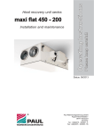
The standard version of the santos consists of the following components:
• Outer casing (A) made of coated sheet steel;
• Inner lining (B) made of high-quality expanded polypropylene (E)PP;
• Connections (C) for the air ducts;
• 2 filters (D) for air filtration. Filter rating: Outside air G4, exhaust air G4;
• 2 energy-saving DC motors (E) with high-speed impeller.
• Highly efficient counter flow heat exchanger (F) or membrane moisture heat exchanger (optional);
• Control PCB (H) with connections for the fans, bypass, temperature sensors (T1 to T4), 3-position switch
with or without the (optional) malfunction and filter display and the (optional) bathroom switch;
• Identification plate (I) with santos data (not visible);
• Condensation drain (J) for discharging condensation from the warm exhaust air;
• Sticker (K) depicting air connections (not visible);
• 230 VAC connection cable and plug with earthing contact (L);
• Display (M) to view data and make settings.
9
EN
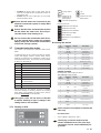
3.2
Technical Specifications
santos 370 DC Basic nL (normal air volume)
Level
Ventilation rate
Power
LOW LEVEL
120 m3/h at 30 Pa
21 W
MEDIUM LEVEL
180 m3/h at 65 Pa
44 W
HIGH LEVEL
260 m3/h at 140 Pa
105 W
MAXIMUM
350 m3/h at 240 Pa
243 W
Level
Ventilation rate
Current
LOW LEVEL
120 m3/h at 30 Pa
0.17 A
MEDIUM LEVEL
180 m3/h at 65 Pa
0.35 A
HIGH LEVEL
260 m3/h at 140 Pa
0.81 A
MAXIMUM
350 m3/h at 240 Pa
1.77 A
Power supply
Supply voltage
230/50 V/Hz
Cos.phi
0.50 - 0.60
Noise level supply air fan (at 0 m)
Level
Ventilation rate
Noise level
LOW LEVEL
120 m3/h at 30 Pa
50 dB (A)
MEDIUM LEVEL
180 m3/h at 65 Pa
59 dB (A)
HIGH LEVEL
260 m3/h at 140 Pa
68 dB (A)
MAXIMUM
350 m3/h at 240 Pa
75 dB (A)
Noise level exhaust air fan (at 0 m)
EN
10
Level
Ventilation rate
Noise level
LOW LEVEL
120 m3/h at 30 Pa
43 dB (A)
MEDIUM LEVEL
180 m3/h at 65 Pa
48 dB (A)
HIGH LEVEL
260 m3/h at 140 Pa
55 dB (A)
MAXIMUM
350 m3/h at 240 Pa
61 dB (A)
santos 370 DC Basic HL (high air volume)
Level
Ventilation rate
Power
LOW LEVEL
140 m3/h at 40 Pa
27 W
MEDIUM LEVEL
180 m3/h at 65 Pa
104 W
HIGH LEVEL
325 m3/h at 215 Pa
196 W
MAXIMUM
350 m3/h at 240 Pa
243 W
Level
Ventilation rate
Current
LOW LEVEL
140 m3/h at 40 Pa
0.21 A
MEDIUM LEVEL
180 m3/h at 65 Pa
0.81 A
HIGH LEVEL
325 m3/h at 215 Pa
1.42 A
MAXIMUM
350 m3/h at 240 Pa
1.77 A
Power supply
Supply voltage
230/50 V/Hz
Cos.phi
0.50 - 0.60
Noise level supply air fan (at 0 m)
Level
Ventilation rate
Noise level
LOW LEVEL
140 m3/h at 40 Pa
54 dB (A)
MEDIUM LEVEL
180 m3/h at 65 Pa
68 dB (A)
HIGH LEVEL
325 m3/h at 215 Pa
74 dB (A)
MAXIMUM
350 m3/h at 240 Pa
75 dB (A)
Noise level exhaust air fan (at 0 m)
Level
Ventilation rate
Noise level
LOW LEVEL
140 m3/h at 40 Pa
45 dB (A)
MEDIUM LEVEL
180 m3/h at 65 Pa
55 dB (A)
HIGH LEVEL
325 m3/h at 215 Pa
59 dB (A)
MAXIMUM
350 m3/h at 240 Pa
61 dB (A)
General specifications
Material of enthalpy exchanger
Material of counter flow heat exchanger
Cellulose
Polystyrene
Material of inner lining
(E)PP / PA / PC
Heating capacity
95%
Weight
39 kg
11
EN
Condensation Drain
Right-Hand Version
Condensation Drain
Left-Hand Version
Condensation
drain 1¼"
(male thread)
Mains Plug
3.3
EN
Dimension Sketch
12
3.4
Preconditions for Installation
You must observe the following points to be able
to assess whether the santos can be installed in a
particular room:
• In addition to observing the instructions contained in this manual you must comply with local safety and installation regulations specified
by, amongst others, public utility companies
when installing the santos.
• When selecting the place of installation ensure
there is sufficient space around the santos for
air connections, supply and exhaust air ducts
as well as for carrying out maintenance work.
• The following installations must be available in
the room:
- Air duct connections.
- 230 V mains power supply.
- Connection for the condensation drain.
• Install the santos in a frost-protected room.
Ensure the condensation water is discharged
frost-free with a downward gradient and using
a siphon.
3.6
Mounting the santos
3.6.1 Wall mounting
We recommend you do not install the unit in
a room with an on average higher level of humidity.
To ensure a good and draught-free ventilation of the dwelling, 10 mm gaps must be left
purposely under the doors inside the dwelling. If these gaps are blocked, for example
with door seals or high-pile carpets, the circulation of air inside the dwelling will stagnate. This would prevent the system from
operating optimally.
3.5
Installing the santos
3.5.1 Transport and Unpacking
Work with due care and attention when transporting
and unpacking the santos.
Remove the unit from the packaging only
immediately prior to mounting the unit.
To protect against the ingress of
3.5.2 Checking the Scope of Supply
Should you discover any damage or missing parts
of the supply product, please contact your supplier
without delay. The scope of supply includes:
• Santos 370 DC Basic;
Check the identification plate to ensure it is the
correct type.
• Mounting brackets;
• Operating Manual
Mount the santos on a wall with a mass of at least
200 kg/m2.
With other walls we recommend the use of a mounting frame to install on the floor (optional). This helps
to avoid the transmission of structure-borne noise
as much as possible.
• Fasten the supplied mounting bracket to the
wall horizontally.
• Connect the condensation drain (not included
in the scope of supply) to the underside of the
santos. The given dimension of 235 mm is intended as a guideline. This value depends on
the type of siphon selected.
• Ensure that at least 1 metre of space is left in
front of the santos to allow future maintenance
work.
3.6.2 Connecting the Air Ducts
Observe the following specifications when fitting air
ducts:
• Install silencers of at least 1 meter in length to
the supply and exhaust air connections of the
unit. For relevant advice, please contact Paul
Wärmerückgewinnung GmbH.
• Fit the air ducts to be connected (minimum
ø160 mm), ensuring they are sealed airtight and
offer as little resistance to the flow of air as possible.
• To guarantee the basic functionality of the balanced ventilation system when utilising flexible
ducting, use only air ducting material from Paul
Wärmerückgewinnung GmbH.
• Ensure the insulation of the intake air and
discharge air ductwork is vapour tight. This
prevents the formation of condensation on the
outside of the ducts.
• If it is not possible to avoid creating a low point
when installing the discharge air ducting from
the discharge air connections on the unit to
the wall opening, then a further condensate
13
EN
•
•
•
drainage line must be connected at the
low point; the reason being discharged air
is saturated with water vapour when confronted with cold outside temperatures and
that causes droplets to deposit on the inside of the ductwork.
If it is planned to install a silencer at the
discharge air connection, then this must
be routed upwards by a bend to protect
it against being soaked by condensation
flowing back out of the discharge air ductwork. When mounting the unit ensure the
condensate can be drained with a good
downward gradient along a longer distance.
When routed across a roof the exhaust air
duct must have a double-walled or insulated roof opening. This prevents the formation of condensation between the layers of
the roof.
To prevent unnecessary temperature losses in both summer and winter we recommend you insulate the supply and exhaust
air ductwork with thermal, vapour-tight insulation.
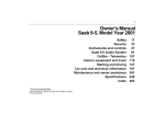
3.6.3 Connecting the condensation drain
santos 370 DC - RIGHT
Exhaust air
Supply air
Discharged air
Outside air
santos - LEFT
Outside air
Discharged air
Supply air
Exhaust air
santos - RIGHT
santos 370 DC - LEFT
The warm exhaust air is cooled by the intake
air in the heat exchanger. As a result, moisture
contained in the inside air condenses in the
heat exchanger. The condensation water that
forms in the heat exchanger is directed towards the siphon.
The connection for the condensation drain has
an outside diameter of 32 mm. This is located
on the underside of the santos.
• Connect the condensation drain with a
pipe or hose to the water seal of the domestic wastewater system.
EN
14
•
•
Position the upper edge of the water seal at
least 40 mm below the condensation drain of
the santos unit.
Ensure that the end of the pipe or hose ends
below the water level.
MENU
OK
OK
Down
Supply air off
supply air on
(LED green)
Exhaust air and
(LED green)
Display read-out:
Ensure that the hose end terminates at least
60 mm below the water level. This will prevent the santos from drawing in air.
3.7
Up
Comfort temperature
Ensure that the water seal connected to the
domestic wastewater system is always filled
with water.
Do not connect the condensate drain directly to the sewage drain system (for example
flowing freely into funnel with condensation
drain at the sewage system)
Call up menu
A
Ventilation level absent
1
Ventilation level low
2
Ventilation level medium
3
Ventilation level high
X X
Menu display
X X
Malfunction code (flashes)
Bypass
•
Accessing the menus
Commissioning the santos
The santos can be put into operation after installation.
Commissioning can be carried out via the P menus
on the unit display. These P menus allow various
settings (in particular for ventilation control) to be
selected for the santos. An overview of the available
P menus is given below:
Sequence
Operating
keys
Display
Description
1
MENU
P2
Time delay values
2
▲+▼
(3 seconds)
P3
Press keys
simultaneously
3
▲
P4
Temperatures
4
▲
P5
Control settings
5
▲
P6
Control settings
6
▲
P7
Malfunction / reset /
Self-test
Menu
Possibilities
P1
View status (from menu P2)
7
▲
P8
0 - 10 V inputs
P2
Set time delay values
8
▲
P9
Status display
P3
Set ventilation levels
P4
View temperatures
P5
Set additional control functions
P6
Set additional control functions
P7
Read and reset malfunctions (and system information)
P8
Set 0 - 10 V inputs
P9
View status (from menu P5)
Settings example
Set the power of the supply air fan at
THE MEDIUM LEVEL to 40%
The P menus P1, P2 and P9 are user accessible
and serve mainly for viewing statuses and setting
time delays. The remaining P menus P3 to P8 are
reserved exclusively for the installer.
The bypass valve will not move in the first
4 minutes following a drop in voltage, if the
setting mode is not activated.
Sequence
Operating
keys
Display
Description
1
MENU
P2
Time delay values
2
▲+▼
(3 seconds)
P3
Press keys
simultaneously
3
OK
P30
Exhaust air fan
Level A
4
▲ (6x)
P36
Select P36
5
OK
50
Current setting
6
▼(10 x or
hold down)
40
Select 40
7
OK
P35
Current value is 40
8
MENU
P3
9
3.7.1 Display on Unit
MENU
1
Fan steps
Some P menus (for example P1 and P9) are
view only.
End (read) menu
•
Press "MENU" (instead of "OK").
The display cannot be used to set the
santos ventilation levels. The arrow keys
can only be used to set the additional programmes.
15
EN
Menu P3 Set ventilation controls
Values for ventilation controls
Sub-menu
Description
Minimum
Maximum
Standard
P30
N/A
0% or 15%
97%
Normal / High
15% / 15%
P31
The power (in %) of the exhaust air
fan FOR THE LEVEL "LOW".
16%
98%
Normal / High
35% / 40%
P32
The power (in %) of the exhaust air
fan FOR THE LEVEL "MEDIUM".
17%
99%
Normal / High
50% / 70%
P33
The power (in %) of the exhaust air
fan FOR THE LEVEL "HIGH".
18%
100%
Normal / High
70% / 90%
P34
N/A
0% or 15%
97%
Normal / High
15% / 15%
The power (in %) of the supply air fan 16%
"LOW".
98%
Normal / High
35% / 40%
The power (in %) of the supply air fan 17%
"MEDIUM".
99%
Normal / High
50% / 70%
P35
FOR THE LEVEL
P36
FOR THE LEVEL
P37
The power (in %) of the supplyf air
fan FOR THE LEVEL "HIGH".
18%
100%
Normal / High
70% / 90%
P38
Current power (in %) of the
exhaust air fan.
-
-
Current %
P39
Current power (in %) of the
supply air fan.
-
-
Current %
Menu P4 View temperatures
Temperature values
Sub-menu
EN
Description
Minimum
Maximum
Standard
P41
Comfort temperature
12 C
28 C
20 oC
P45
Current value of T1
(= temperature of outside air)
-
-
Current oC
P46
Current value of T2
(= temperature of supply air)
-
-
Current oC
P47
Current value of T3
(= temperature of exhaust air)
-
-
Current oC
P48
Current value of T4
(= temperature of discharged air)
-
-
Current oC
16
o
o
3.7.2 P Menus for the Installer
Menu P5 Setting additional control functions
Values for additional control functions
Sub-menu
Description
Minimum
Maximum
Standard
P50
Activating the
fireplace control.
0 (= No)
1 (= Yes)
0
P51
n/a
0 (= No)
1 (= Yes)
0
P52
n/a
0
3
2
P54
Indicate presence of a bypass
0 (= No)
1 (= Yes)
1
Note:
The santos is fitted with a bypass valve as standard equipment. Therefore, the value
can be left at '1'.
P56
Setting the requisite
volume of air for the dwelling.
• nL: "Normal air volume".
• HL: "High air volume".
nL
HL
HL
Note:
The setting undertaken in P56 for the air volume ("nL" or "HL") forms the basis for
setting the air specifications and hence for setting the fans.
P57
Santos setting.
• Li = "Left-hand version"
• Re = "Right-hand version".
Li
Re
Li
Note:
The santos unit is correctly set ex works.
• Refer also to the identification plate for this data.
P58
Enter the priority for the control set- 0
ting.
• 0; Priority for high level INCLUDING
analogue input.
• 1; Priority for high level EXCLUDING analogue input.
1
0
P59
Indicate the presence of the enthalpy exchanger.
2 (= Yes)
0
0 (= No)
• 0; No enthalpy exchanger installed
• 1; Enthalpy exchanger with RH
sensor installed
• 2; Enthalpy exchanger without RH
sensor installed
Note:
It is not possible to connect an RH sensor to the santos unit. Consequently, select
Option 2, if an enthalpy exchanger is installed.
Menu P6 Setting additional control functions
Values for additional control functions
Sub-menu
P60
Description
N/A
Minimum
0 (= No)
Maximum
3 (= Yes)
Standard
0
Note:
Keep this setting to standard.
17
EN
Menu P7 View and reset malfunctions (and system information)
Values (malfunction) information
Sub-menu
Description
Minimum
Maximum
Standard
P70
Current software version
Software version number (without "v")
P71
Last malfunction.
Code compliant alarm and malfunction messages
P72
Last malfunction but one
Code compliant alarm and malfunction messages
P73
Last malfunction but two
Code compliant alarm and malfunction messages
P74
Reset a malfunction on the santos
0
P75
Restore factory settings
1
0
0
1
0
• Press and hold down the "OK" key
on the digital control panel to restore
factory settings.
This action will restore the original
factory settings.
Note:
After a complete reset, the santos prompts you to
re-enter “nL / HL” (see P56) and “Li / Re” (see P57)
selection.
After a complete reset, all settings in menus P2 and
P3 and the existing controls P5 and P6 have to be
set again.
P76
Santos self-test
0
1
0
Note:
The santos switches to the highest level immediately after the selftest is activated. In addition, the bypass valve also opens and closes
immediately after the self-test is activated.
P77
Reset counter filter soiled
0
1
0
Note:
This control command resets the counter that the filter warning indicator evokes. This allows the filter to be cleaned or replaced before
the filter warning is indicated.
Menu P8 Analogue control settings
Values (malfunction) information
Sub-menu
EN
Description
Minimum
Maximum
Standard
850
N/A
0
1
0
851
N/A
0
1
0
852
N/A
0
100
50
853
N/A
0
99
0
854
N/A
0
100
100
855
N/A
0
1
0
856
N/A
0
100
-
18
3.8
Setting the Air Specifications
Settings must be made to the santos unit following installation.
These can be undertaken using the air specifications of the santos shown above.
19
EN
The standard settings for the santos, nL, are as follows:
Level LOW
35%
Level MEDIUM
50%
much:
– Adjust the valves further.
10. Check the whole system again after adjusting
all of the valve levels.
11. Switch on the santos unit (again) and set it to
ventilation level 2.
– Display: Simultaneously press the keys "
70%
Level HIGH
The standard settings for the santos, HL, are as follows:
Level LOW
40%
Level MEDIUM
70%
Level HIGH
90%
To set the santos (following installation) proceed as
follows:
1. Set the santos to the programming mode.
- Display: Simultaneously press the keys
"
" and "
" for at least 3 seconds
until "InR" is displayed.
When in the setting mode the damper of the
bypass valve are always closed. The santos
automatically switches off the setting mode
after 30 minutes.
2. Close all windows and outside doors.
3. Then close all inside doors.
4. Check the presence of air circulation systems in
the building (at least 12 cm2 per l/s).
The air circulation systems in the building
must achieve at least 12 cm2 per l/s.
" and "
" for at least 3 seconds until
"InR" is no longer displayed.
3.9
Service by the Installer
As the installer you are obliged to service your santos as follows:
• Inspect the heat exchangers and fans.
These maintenance procedures are described briefly in more detail in the following sections.
Failure to (regularly) carry out maintenance
procedures on the santos will impair the
long-term performance of the balanced ventilation system.
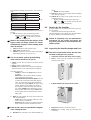
3.9.1 Inspecting the Heat Exchanger and Fans
Check the condensation drain, the fans and
the heat exchanger every 2 years.
1. Isolate the unit from the mains power supply
2. Lift the front panel (A) upwards and remove
from the santos unit.
5. Check, if both fans function in the three speed
ranges.
6. Set the santos to high speed.
7. Install all the valves and set them as detailed in
the instructions or as in the reference dwelling.
If no data is known:
– Install the valves and open them as far as
possible.
– Measure the air volumes, first the supply
air and then the exhaust air.
– If the measured air volumes differ from the
nominal air volumes by more than approx.
10%, and if the majority of the deviations
are in the plus range, adjust the fan so that
all the deviations are in the plus range. If
the majority of the deviations are in the minus range, adapt all the deviations so that
they are all in the minus range. Ensure also
that a supply and an exhaust valve remain
fully open.
8
Alter the fan settings in the P menus P30 and
P37 via the display.
– Select the lowest possible setting to minimise energy consumption.
– Ensure that the ratio of air volumes between
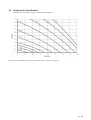
high, medium and low remains the same.
Refer to the santos air specification diagram
when setting the fans.
9. Should the air volumes set to date still differ too
EN
20
3. Pull the handles (B) away from the santos.
4. Remove the filters (C) from the santos.
5. Remove the sealing plate by removing the
screws (E).
the coloured side surfaces and shake out all
the water.
Cleaning the enthalpy exchanger:
– Follow the instructions for cleaning displayedon the frontside of the enthalpy exchanger.
Do not use aggressive or solvent-based
cleaning agents.
When installing the sealing plate, its underside must first be inserted behind
the raised edge to ensure a good seal is
achieved.
santos – Left-hand version
6. Pull the strap (F) to remove the heat exchanger
(G) and the drain plate (H).
7. Remove the bypass duct (I) from the left-hand
version of the santos.
Do not install the heat exchanger yet; proceed as follows to remove, inspect and, if
necessary, clean the fans.
10. Remove the plastic panel (I) located in front of
the PCB by loosening the two screws.
11. Disconnect the connectors (J) and the earth wire
from the PCB, and completely remove the cables
as well as both grommets (K).
12. Remove the complete volute fan casing (L) by
pressing in the click-fasteners (M).
13. Remove the inlet cone (N) by pressing in the
click-fasteners around the volute fan casing.
14. Clean the fans (O).
santos – Right-hand version
6. Remove the bypass duct (I) from the right-hand
version of the santos.
7. Pull the strap (F) to remove the heat exchanger
(G) and the drain plate (H).
Use a soft brush to clean the fan impellers.
Remove dust using a vacuum cleaner.
Take care not to damage the fan impellers.
Take care not to damage the temperature
sensor.
15. Install all the parts again in the
reverse order.
16. Reconnect the unit to the mains power supply.
17. Initiate the self-test in line with menu
P76.
8. Remove the heat exchanger (G) from the drain
plate (H).
There may still be water in the heat exchanger!
9. Clean the heat exchanger, if necessary.
– To clean immerse the heat exchanger in
warm water (max. 40 °C).
– Rinse the heat exchanger thoroughly with
warm tap water (max. 40° C).
– Hold the heat exchanger with both hands on
Refit the drain plate (H) again correctly below
the heat exchanger. The holes in the drain
plate must be on the side of the condensation drain.
Tighten the screws to a maximum torque of
1.5 Nm. This corresponds roughly to level 2
of a normal cordless drill.
21
EN
3.10 Malfunctions
In the event of a malfunction in the santos
a warning message is generally displayed on the
display of the digital control panel.
However, not all malfunction messages are displayed on the display of the digital control panel,
even if there is a malfunction (or problem). Both
types of malfunction (or problem) are described
briefly in the following sections.
3.10.1 Malfunction messages displayed
Below is an overview of the malfunction messages
that are shown on the display of the digital control
panel.
Code
Description
A1
NTC sensor T1 defective.
(= temperature of outside air)
A2
NTC sensor T2 defective.
(= temperature of supply air)
A3
NTC sensor T3 defective.
(= temperature of exhaust air)
A4
NTC sensor T4 defective.
(= temperature of discharged air)
A5
Bypass motor malfunction.
A6
n/a
A7
n/a
‚Fil‘ ‚tEr‘ Display replace filter
E1
Exhaust air fan not working.
E2
Supply air fan not working.
EA2
No communication with
enthalpy sensor.
Ensure that the electrical connections do
not come into contact with moisture.
EN
22
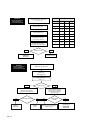
3.10.2 Overview of Malfunctions
The graphic below offers an overview of the above messages that can be viewed on the display of the control
panel in the event of a malfunction.
’FiL‘ ’tEr’ on the display
and/or FilterI
on the keypad display
Press OK
OK
or
until no longer displayed
Isolate from
mains supply
Clean
or
replace filters
Reinsert
the filters
Reconnect
mains supply
E1 / E2
WARNING!
Exhaust air/supply
air fan malfunction
Danger of death from
live components –
do not touch the PCB!
Remove filters,
plastic front and sealing plate
Yes
230 VAC
applied to fan
connection on PCB?
Isolate from mains supply!
Replace PCB
ATTENTION:
Reset unit
Activate self-test
(P76 to 1)
Yes
Control voltage
(1.5–10 VDC)
applied to fan?
Isolate from mains supply!
Remove the heat exchanger and
foam part of bypass and replace the fan
ATTENTION:
Turn on the unit again
No
No
Isolate from mains supply!
Replace PCB
ATTENTION:
Turn on the unit again
Left-hand or right-hand version of santos ?
Refer to label on electronics carriage beside PCB
VDQWRV/HIWKDQGHGH[KDXVWIDQRQULJKW
VDQWRV5LJKWKDQGHGH[KDXVWIDQRQOHIW
23
EN
A1 / A2 / A3 / A4
7HPSHUDWXUHVHQVRUPDOIXQFWLRQ
7 7 7 7
ATTENTION!
WARNING!
Risk
of electrocution:
Danger
of death from
dolive
notcomponents
touch the PCB,
–
the
pre-heater
element
do not
touch the
PCB!
or the afterheater
5HVLVWDQFH>.ȍ@
Temperature
>&@
MIN.
MID.
MAX.
5HPRYHWKH
PDOIXQFWLRQLQJVHQVRU
V
FRQQHFWRUIURPWKH3&%
&KHFNWKHUHVLVWDQFHRI
WKHPDOIXQFWLRQLQJVHQVRU
DFFRUGLQJWRWKHDGMDFHQWWDEOH
'LVFRQQHFWWKHSRZHU
5HPRYHILOWHUV
IURQWDQGPHWDOFRYHU
5HVLVWDQFHRND\"
<HV
1R
5HSODFH3&%
ATTENTION:
Reset unit!
5HSODFH
WHPSHUDWXUHVHQVRU
A5
WARNING!
Danger of death from
live components –
do not touch the PCB!
Malfunction bypass motor
Remove filters,
plastic front
and sealing plate
Activate self-test
(P76 to 1)
Motor running?
Yes
Isolate from mains supply
Remove motor and the
gearwheel with plastic part
Yes
Replace
gearwheel
EN
24
Gearwheel defective?
No
Check connection on PCB;
12 VDC must be applied
if the motor is to operate
(see menu P76)
No
Replace
motor
Yes
Power applied
to PCB?
Isolate from mains supply!
Replace motor
No
Isolate from mains supply!
Replace PCB
ATTENTION:
Reset unit
EA2
Malfunction
Set P59 correctly
Reset the unit
(P74 on 1)
A6
Malfunction
Set P51 on "0"
Reset the unit
(P74 on 1)
A7
Malfunction
Set P51 on "0" and
P57 to the correct value.
(see rating plate)
Reset the unit
(P74 on 1)
25
EN
3.10.3 Malfunctions (or Problems) not Displayed
This section gives an overview of the malfunctions (or problems) that are not displayed.
Problem / Malfunction
Cause
Check / Remedy
All OFF
Supply voltage
Check the fuse on the controller PCB.
• If the fuse is OK the PCB is defective.
No supply voltage
Mains power supply has failed.
High air delivery
Bypass remains closed
temperature in sum- The santos is still in winter mode.
mer
Lower the comfort temperature.
Low supply air temperature in winter
Bypass remains open
Increase the comfort temperature.
No or too little supply air; shower remains wet
Filter clogged
Replace the filters.
Valves clogged
Clean the valves.
Heat exchanger clogged with
dirt
Clean the heat exchanger.
Heat exchanger frozen
Thaw the heat exchanger.
Fan dirty
Clean the fan.
Ventilation ducts clogged
Clean the ventilation ducts.
santos is set to frost mode
Wait until warm-up phase occurs
Fan bearings defective
Replace the fan bearings.
Unusual
noises
Leaking condensation
Wired 3-position
switch does not
function
EN
26
Wait until the santos switches to summer mode.
Fan settings
Change the ventilation control settings.
Scraping noise
• Siphon is empty
• Siphon does not seal
Install the siphon again.
Whistling noise
• Air leak somewhere in the system
Seal the air leak.
Air flow noises
• Valves do not seal against duct
• Valves not open sufficiently
Install the valves again.
Reset the valves.
Condensation drain clogged
Clean the condensation drain.
Condensation from the exhaust air
Check whether the connections
duct does not flow into the condensa- are properly joined.
tion tray
Wiring not correct
Switch is defective
Check the circuit of the
3-position switch by measuring
the voltage:
• Voltage
only between N and L3:
[The fans operate at level 1].
• Voltage
only between N and L3 and N and
L2:
[The fans operate at level 2].
• Voltage
only between N and L3 and N and
L1 or between N and L3, N and
L2, N and L1:
[The fans operate at level 3].
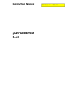
Supply air
T2
T3
Brown
TRI
1
Blue
FIL
Brown
VENT.
Blue
T2/T4
VENT.
BYP/PIE T1/T3
+
-
Black
Red
White
Brown
White
Brown
Blue (-)
Yellow (0-10V)
White (
)
M
Green/ Yellow
Bypass flap
M
(N) Blue
(L3) Brown
VENT.
T2/T4
VENT.
BS
Red
Black
White
Brown
White
Brown
White (
)
Yellow (0-10V)
Blue (-)
Boost ventilation switch
(bathroom switch)
T4
T1
Preheater flap
Green/ Yellow
RJ11
RS232
M
Green/ Yellow
BYP/PIE T1/T3
M
Extract air
J1
GND
GND
12V
RX
TX
GND
12V
B
A
A2
RS232
RS485
RS485
Enthalpy Hybalans KFB
GND
12V
B
A
12V
A1
0-10V
0-10V
RS232
PC
Plastic film keybord
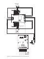
Appendix 1 Terminal connection plan santos (F) 370 DC left hand side
Extract air
T4
T1
Brown
TRI
1
Blue
FIL
Brown
VENT.
Blue
T2/T4
VENT.
BYP/PIE T1/T3
+
-
Blue
Red
White
Brown
White
Brown
Blue (-)
Yellow (0-10V)
White (
)
M
Green/ Yellow
Preheater flap
M
(N) Blue
(L3) Brown
VENT.
BYP/PIE T1/T3
T2/T4
VENT.
BS
M
Supply air
J1
GND
GND
12V
RX
TX
GND
12V
B
A
A2
RS232
RS485
RS485
Enthalpy Hybalans KFB
GND
12V
B
A
0-10V
0-10V
RS232
PC
12V
A1
Green/ Yellow
Red
Black
White
Brown
White
Brown
White (
)
Yellow (0-10V)
Blue (-)
T2
T3
Bypass flap
Boost ventilation switch
(bathroom switch)
M
Green/ Yellow
RJ11
RS232
Plastic film keybord
Appendix 2 Terminal connection plan santos (F) 370 DC right hand side
Date: 14/11/12
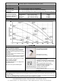
Technical Data
We reserve the right to make
changes favouring technical
progress.
Mechanical Ventilation Heat Recovery Unit
santos (F) 370 DC
View:
Versions:
Right hand side version
(Left hand side version)
santos 370 DC - with standard heat exchanger
santos F 370 DC - with option moisture heat exchanger
santos 370 DC
Dimensional sketch:
Technical Specification:
Heat exchanger:
*depending on outside air and
extract air condition
Fans:
Filters:
Housing:
Front cover:
Duct connections:
Condensate drain:
Bypass:
Weight
Electrical connection:
Power input:
Protection type:
Protection class:
Application limits:
Material:
Frost limit:*
Plastics (standard heat exchanger, PAUL patented – the santos 370)
< 0 °C
Polymer membrane (enthalpy - the santos F 370)
< -8 °C
EC radial fans with integrated electronics
G4 (intake and extract air), Option: pollen filter F7 (intake air)
Galvanised steel sheet, light grey RAL 7035, powder coated, thermal bridge free, inner
lining made of expanding polypropylene (E) PP for heat and sound insulation
Plastic, aquamarine RAL 5021, varnished
DN 160, a vertical and/or horizontal connection possibility for every air type
1¼“ outer thread
Motorised summer bypass, sensor controlled
39 kg
230 Vac, 50 Hz, ready for connection
250 W
IP 22 (as per DIN 40050)
Ι (as per EN 60 335)
-20 to 50 °C (relates WRG integrated electronic assemblies)
© Paul Wärmerückgewinnung GmbH • August-Horch-Straße 7 • 08141 Reinsdorf • Germany
Tel: +49(0)375-303505-0 • Fax: +49(0)375-303505-55 • E-Mail: [email protected] • Internet: www.paul-lueftung.de
Installation position:
• Wall mounted, horizontal (Lower edge at least 235 mm above finished floor level)
• vertically upright on an adjustable assembly frame (option)
Operating Data:
Efficiency criterion:
Air flow:
Heat recovery rate:
Heat recovery rate
enthalpically:
Sound pressure level:
as per DIN EN ISO 3743-1
Inspection room parameter:
Reverberation chamber 25 m³
Reverberation time 0,5 s
Distance 1,5 m
0,29 Wh/m³ at 233 m³/h, 100 Pa
40 m³/h to 400 m³/h
92,7 % at 150 m³/h (santos 370 DC acc. NEN-EN 308)
84 % at 143 m³/h (santos 370 DC acc. passive house-certificate)
114 % at 233 m³/h (Enthalpy of the supply air at humidy of the intake air acc. DIN 4719)
Level
unoccupied level
low level
medium level
high level
Sound pressure level
(20 %, 50 m³/h, 10 Pa)
(35 %, 100 m³/h, 45 Pa)
(70 %, 225 m³/h,195 Pa)
(90 %, 275 m³/h, 315 Pa)
19 db(A)
31 dB(A)
52 dB(A)
58 dB(A)
Characteristic curve:
Control unit:
Automatic frost protection
Comfort temperature regulation
Filter change announcement (time-based)
Balance reconciliation between extract air
and supply air fan for each level in 1%-steps
adjustable
• Connection type for boost ventilation switch
(bathroom switch)
• Fault history of the last three error messages
• Simultaneous fireplace operation possible
•
•
•
•
•
• Control functions with external 0-10 V input
(CO2, humidity, air quality)*
• Time program per week*
• Separated switching on / off supply air fan
and extract air fan *
* only with control panel Sealed keypad
Control panels:
3-Position-Switch (version Basic)
• 3 fan speeds are possible
• Surface or flush mounted
Cable connection for control:
YSLY-JZ5x0,5, by the customer
Sealed keypad Concealed or wall mounted
• 4 fan speeds are possible
• Operating mode selection: Supply air and
extraction air, only supply air, only extraction
air
• A free programmable weekday timer
• Additional ventilation regulations (CO2,
humidity, air quality) adjustable
• Surface or flush mounted
Cable connection for control:
protected Twisted-Pair-Cable 4x0,34; max. 10 m; by
the customer
Please note:
• Installation must be in a frost free place, if possible >10 °C.
• The cables for sensors should not be laid out parallel to 230/400 VAC lines (20 cm minimum interval) and should not be
laid out in loops.
• There is an additional module for monitoring low pressure for simultaneous operation with fireplaces with a switching off
function for the ventilation device and/or exhaust hood with escaping air connection.
© Paul Wärmerückgewinnung GmbH • August-Horch-Straße 7 • 08141 Reinsdorf • Germany
Tel: +49(0)375-303505-0 • Fax: +49(0)375-303505-55 • E-Mail: [email protected] • Internet: www.paul-lueftung.de
Date: 22/08/12
Checklist A
Maintenance by customer
Subject to change
in the interest of technical
progress.
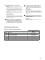
Maintenance Work
Enter date in the quarter
1. Change both filters in the MVHR unit (change every 90 days)
Quarter
Year
I
II
III
IV
201...
201...
201...
201...
201...
201...
201...
201...
201...
201...
2. Clean extract air prefilter / filter in extract air valves (change approx. every 2 months)
Quarter
Year
I
II
III
IV
201...
201...
201...
201...
201...
201...
201...
201...
201...
201...
3. Change prefilter in fresh air line (outdoor air intake - also at ground heat exchanger) – all 6-12 months
Quarter
Year
I
II
III
IV
201...
201...
201...
201...
201...
201...
201...
201...
201...
201...
Simplified formula for determining the local heat recovery rate η
η=
tSup − t Int
tExt − t Int
Legend: tInt - intake air temperature
tExt - extract air temperature
tSup- supply air temperature
Note:
Air temperatures are to be measured in
nominal ventilation mode with volume
flow balance and sensor arrangement
acc. to DIN EN 308!
© Paul Wärmerückgewinnung GmbH • August-Horch-Straße 7 • 08141 Reinsdorf • Germany
Tel: +49(0)375-303505-0 • Fax: +49(0)375-303505-55 • E-Mail: [email protected] • Internet: www.paul-lueftung.de
Date: 23/08/12
Subject to change
in the interest of technical
progress.
Checklist B
Maintenance by skilled personnel
Maintenance
Inspection of MVHR unit acc. to DIN 1946-6 appendix E (normative) and appendix F (informatory)
Hygiene check acc. to VDI 6022, item 5 and table 6
Informal report for comments on MVHR unit's condition
− Use additional sheet of paper for adding reports of subsequent years
No.
Components
Action / Interval (in months) 1)
Result
201... 201... 201...
Components cleaned?
(Heat exchangers, condensate
6
yes / no
pan, siphon, post heater, unit housing)
1)
3
yes / no
Filter test, filter replacement
3-62)
Frost protection device functional?
6
yes / no
1
Fan / MVHR unit
Structure-borne-noise transmis122)
yes / no
sion, fixings are avoided?
Preheater / vaporizer / heat ex6
yes / no
changer are not contaminated?
Preheater / vaporizer / heat ex6
yes / no
changer are cleaned?
2)
Status indicators are working?
12
yes / no
Working?
3
yes / no
Condensate
2
drain and siphon Condensate disposal OK?
3
yes / no
Cable connections and clamp
2)
yes / no
12
Electronic confixing secure?
3
trols
2)
Control units working?
12
yes / no
Inner duct surface tested for con12
yes / no
tamination
Cleaning done (if required)?
yes / no
Air ducts / heat
Heat insulation and vapor barrier
2)
4
12
yes / no
insulation
OK?
Flexible connections between
2)
yes / no
MVHR and air ducts OK?
12
Air ducts OK?
2)
yes / no
Changeover working?
12
Outdoor air intake free?
12
yes / no
Condition of prefilter OK?
12
yes / no
Ground to air
1)
5
heat exchanger
12
Filter changed?
yes / no
2)
(if available)
6
Condensate drain OK?
3
yes / no
Corrosion OK?
3
yes / no
Fan / MVHR unit
and fireplace
Safety device with firing installation
6
122)
yes / no
operating mode
working?
(if available)
Filters of correct filter class in122)
yes / no
Other filters, filter stalled?
7
condition
1)
Filter changed?
3-12
yes / no
2)
yes / no
Fit and lock OK?
12
Extract air / sup- Filters of correct filter class in2)
12
8
yes / no
stalled?
ply air outlet
2)
Filter, filter condition OK?
6
yes / no
2)
yes / no
Free cross-section?
12
Overflow air
9
No structure-borne / airborne noise
2)
ducts
12
yes / no
transmission?
Enter result
−
−
−
1)
2)
201...
Figures: Measure interval in months acc. VDI 6022
Action / interval in months – indication acc. Paul Wärmerückgewinnung GmbH
© Paul Wärmerückgewinnung GmbH • August-Horch-Straße 7 • 08141 Reinsdorf • Germany
Tel: +49(0)375-303505-0 • Fax: +49(0)375-303505-55 • E-Mail: [email protected] • Internet: www.paul-lueftung.de
201...
Date: 23/08/2012
Air Flow Report
Subject to change
in the interest of technical
progress.
Operating condition, functional check1),
instruction
Customer data
Surname:
First name:
Tel:
Street:
ZIP:
Town:
Serial-No.:
Built:
Construction project:
MVHR-type:
Measured data
Measuring equipment used:
Fault descriptions during
measurement:
Indoor temperature2)
Outdoor temperature2)
Weather2)
Filter condition on calibration
clean
used for approx. ... days
very dirty
Supply
Extract air
Building moisture Fan speed ratio
Extract air / Supply air
condition:
..… % RH without
ventilation mode ...........................
Supply air
No.
Room description
m³/h
Extract air
No.
Room description
m³/h
Project data
Project data
m³/s
Ventilation step:
%
Measured data
m³/h
m³/s
m³/s
Ventilation step:
%
Measured data
m³/h
m³/s
Pel =
W (2 fans)
1)
The volumetric air flow is measured during normal MVHR operation 3) as agreed.
2)
acc. to DIN EN 14134, Item 7.3.1.5.
3)
acc. to DIN EN 14134, Item 7.4.1. b) end
4)
acc. to DIN 1946-6 MVHR unit has to run continuously, except for times of maintenance or repair. Use lowest
ventilation step or intermittent unoccopied program in times of absence.
The user has been instructed on the hygienic requirements 4) for the operation of the MVHR unit
Customer has been advised that winter and summer operation influence the interior air humidity If too dry air (<30%
RH in winter) can create a moist heat exchanger transferring remedy - this can be supplied in many PAUL
devices.
No parts other than genuine PAUL parts (e.g. filters) shall be used, otherwise the warranty will be void
The warranty period starts with delivery ex works
Date: ...............................
Signatures: ...................................................................................................................
Startup personnel / Plumber
User
© Paul Wärmerückgewinnung GmbH • August-Horch-Straße 7 • 08141 Reinsdorf • Germany
Tel: +49(0)375-303505-0 • Fax: +49(0)375-303505-55 • E-Mail: [email protected] • Internet: www.paul-lueftung.de
Commissioning and handover
certificate
Date: 23/08/12
Subject to change in the
interest of technical progress.
Completeness and performance
verifications acc. to DIN 1946-6
Customer data
Surname:
First name:
Tel:
Street:
ZIP:
Town:
Serial-No.:
Built:
Construction project:
MVHR-type:
Completeness
No.
1
Device
Supply air duct
2
Supply air outlets
3
Overflow air outlets
Ausführung
Result
- Version as planned
- Cleaning possible
- Configuration as planned
- Version as planned
- Cleaning possible
- sufficient distance from the
yes / no
yes / no
- Configuration as planned
- Version as planned
- Configuration as planned
- Version as planned
- Cleaning possible
- Pre-filter provided as planned?
- Cleaning possible
- Cleaning possible
- working?
yes / no
yes / no
yes / no
yes / no
yes / no
yes / no
yes / no
yes / no
yes / no
yes / no
yes / no
yes / no
yes / no
4
Extract air outlets
5
6
7
Extract air duct
Extract air fan
Control unit
8
Filters, optional
- Possibility to change
- or clean
yes / no
9
Heat exchanger for heat recovery
- Cleaning possible
yes / no
10
11
12
13
14
15
Extract air heat pump, optional
Condensate drain, optional
Ground to air heat exchanger, optional
Duct heater, optional
Solar panel
Documentation / manual
- Cleaning possible
- working?
- Cleaning possible
- Cleaning possible
- Cleaning possible
- available
yes / no
yes / no
yes / no
yes / no
yes / no
yes / no
Function
1
Ready to use in standard mode (nominal
ventilation), as planned
Result OK
further steps necessary
yes / no
yes / no
2
Different modes possible, as planned
Result OK
further steps necessary
yes / no
yes / no
3
Power consumption
Result OK
further steps necessary
yes / no
yes / no
Confirmation
Date: ................................... Signature/Stamp:.......................................................................................
Startup personnel / Plumber
© Paul Wärmerückgewinnung GmbH • August-Horch-Straße 7 • 08141 Reinsdorf • Germany
Tel: +49(0)375-303505-0 • Fax: +49(0)375-303505-55 • E-Mail: [email protected] • Internet: www.paul-lueftung.de
Paul Wärmerückgewinnung GmbH
August-Horch-Straße 7
08141 Reinsdorf
Germany
Tel.: +49(0)375 - 303505 - 0
Fax: +49(0)375 - 303505 - 55
CE DECLARATION OF CONFORMITY
Product description: Mechanical ventilation heat recovery (MVHR) unit
santos 370 DC - range
Complies the Directives:
Directive 2004/108/EC of the European Parliament and of the Council of 15 December 2004 on the
approximation of the laws of the Member States relating to electromagnetic compatibility and repealing
Directive 89/336/EEC
Applied standards:
EN 61000-6-1 Electromagnetic compatibility (EMC) - Part 6-1: Generic standards - Immunity for residential, commercial
and light-industrial environments
EN 61000-6-3 Electromagnetic compatibility (EMC) - Part 6-3: Generic standards - Emission standard for residential,
commercial and light-industrial environments
EN 55011 Industrial, scientific and medical equipment - Radio-frequency disturbance characteristics - Limits and
methods of measurement
DIRECTIVE 2006/42/EC of the European Parliament and of the Council of 17 May 2006 on machinery,
and amending Directive 95/16/EC (recast)
Applied standards:
EN ISO 12100-1 Safety of machinery - Basic concepts, general principles for design - Part 1: Basic terminology,
methodology
EN ISO 3744 Acoustics - Determination of sound power levels and sound energy levels of noise sources using sound
pressure - Engineering methods for an essentially free field over a reflecting plane
EN ISO 5136 Acoustics - Determination of sound power radiated into a duct by fans and other air-moving devices - Induct method
DIRECTIVE 2006/42/EC of the European Parliament and of the Council of 12 December 2006 on the
harmonisation of the laws of Member States relating to electrical equipment designed for use within
certain voltage limits
Applied standards:
EN 60730-1 Automatic electrical controls for household and similar use - Part 1: General requirements
EN 60730-2-15 Automatic electrical controls for household and similar use - Part 2-15: Particular requirements for
automatic electrical air flow, water flow and water level sensing controls
Reinsdorf, 27th of August 2012
Paul Wärmerückgewinnung GmbH
Michael Pitsch
CEO
849050689-0811-EN