1
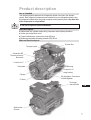
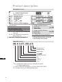
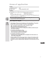
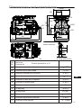
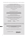
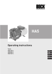
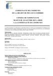
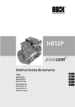
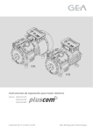
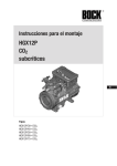
HG12P
Operating instructions
Types:
D
HG12P/75-4
HG12P/90-4
HG12P/110-4
GB
F
E
HG12P/60-4S
HG12P/75-4S
HG12P/90-4S
HG12P/110-4S
I
Foreword
Dear Customer,
Bock compressors are top-quality, reliable, service-friendly quality products. Please comply with the
following operating and maintenance instructions so that you can benefit from all advantages to the
full and use your refrigerating system throughout its entire service life. If you have any questions about
installation, operation and accessories, please contact our technical service or your refrigerating system wholesale dealer or our representative. The Bock service team is available by phone under +49
7022 9454-0, by e-mail under [email protected] or on the internet under www.bock.de. In addition, for
German speaking countries we have set up a toll-free hotline under 00 800 / 800 000 88 from Monday
to Saturday between 8 a.m. and 9 p.m. Any suggestions you may have regarding the on-going development of our compressor, equipment and parts programme are welcome at any time.
Please read the information summarised for you in this manual before starting work.
It contains important instructions for safety, installation, initial commisioning and handling. In
Please readspare
the information
summarised for you in this
addition you will find information on maintenance,
parts and accessories.
manual before starting work.
Some instructions are identified by special symbols with the following meaning:
It contains important instructions for safety, installation, initial
WARNING! This symbol is used to indicate that inaccurate compliance or total
commissioning and handling. In addition you will find informafailure to comply with the instructions could cause injury to persons or damage
tion on maintenance, spare parts and accessories.
to the comperssor or refrigerating machine.
Some instructions are identified by special symbols with the
DANGER! This symbol refers
to instructions
following
meaning: for avoiding direct serve dangers to
persons.
WARNING! This symbol is used to indicate
that inaccurate compliance or total failure to
DANGER! This symbol refers to instrucion
for avoiding
direct serve
dangers
comply with
the instructions
could
cause to
injury
persons or plant by electrical current.
to persons or damage to the compressor or
refrigerating machine
This symbol indicates important additional
should
DANGER!instructions
This symbolwhich
refersyou
to instructions
for
observe during your work.
avoiding direct severe dangers to persons.
The high quality standart of Bock compressors is guaranteed also by on-going furtherdevelopment
DANGER! This symbol refers to instructions for
of machine, features and accessories. This could possible results in non conformities between this
avoiding direct severe dangers to persons or
present manual and your compressor. Please understand tha it is not possible for any claims to be
plant by electrical current.
derived from the details, illstrations and descriptions.
This symbol indicates important additional
instructions which you should observe during
Your team at
your work.
- Subject to modification Bock Kältemaschinen GmbH
The high quality standard of Bock compressors is guaranteed
also by on-going further development of machine, features
Bock Kältemaschinen GmbH
and accessories. This could possibly result in nonconformities
Postfach 11 61
between this present manual and your compressor. Please
D-72632 Frickenhausen
understand that it is not possible for any claims to be derived
Benzstr. 7
from the details, illustrations and descriptions.
D-72636 Frickenhausen
Your team at
Fon: +49 7022 9454-0
Bock Kältemaschinen GmbH
Fax: +49 7022 9454-137
[email protected]
www.bock.de
- Subject to modifications -
D
GB
F
E
I
Contents
Safety instructions
Product description
Use as intended
Short description
Main and functional parts
Name plate
Type code
Areas of application
Coolant
Oil filling
Limits of application diagrams
Installation
Setting up
Pipe connections
Pipes
Shut-off valves
Electrical systems
Electrical connection
Connection of the driving motor
Wiring diagram for direct start 230 V ∆ / 400 V Y
Electronic trigger MP 10
Connection of the electronic trigger MP 10
Functional test of the electronic trigger MP 10
Recommendation for contactor selection
Start-up
Preparations for start-up
Pressure strength test
Tightness test
Evacuation
Filling with coolant
Start-up
Liquid sluggings
Connection of the oil level regulator
Maintenance
Safety instructions
Spare part recommendation
Accessories
Screwed unions
Lubricants
Decommissioning
Technical data Dimensions and connections
Conformity and manufacturer‘s declaration
Page
4
5
7
9
12
16
18
D
GB
F
20
21
22
E
I
Safety instructions
The Bock refrigerating compressors named in the title are intended for installation
in machines (within the EU according to EU directive 98/37/EC Machinery Directive,
97/23/EC Pressure Equipment Directive and 73/23/EC Low Voltage Directive). Initial
commissioning is only allowed when the compressor has been installed according to
these instructions and the whole machine in which it is integrated has been tested and
accepted according to the statutory regulations.
Bock refrigerating compressors have been designed to state-of-the-art engineering.
Safety for the user is given particular priority during the design stage. However, it is
always possible for the refrigerating machine and operation thereof to pose unavoidable
residual risks. This is why these instructions must be observed carefully by every
person working at the compressor.
Work on the compressor may only be carried out by persons whose technical training, skills and experience together with their knowledge of pertinent regulations and
documentation means that they are capable of assessing the work to be carried out and
detecting any possible dangers.
Safety instructions
Safety
instructions
Any handling of the compressor is permissible only by skilled personnel!
Observe national safety regulations, accident prevention regulations,
generally recognized technical rules as well as specific regulations (EN 378,
EN 60204, EN 60335 etc.).
Carry compressors only with hoists with sufficient lifting power.
Operate compressors only in refrigeration plants with approved refrigerants.
Do not exceed permissible operating pressure – even for testing purposes.
Caution! Compressors are filled with protective gas ex works (approx. 3 bar
nitrogen). Avoid possible injuries to skin and eyes! Wear goggles! Relieve
pressure of compressors before connection to the refrigeration system!
Before start-up check compressor for transport damage.
Before start-up check that all components mounted by the user are installed
correctly and connected pressure-tight with the compressor (pipes, plugs,
union nuts, replaced components etc.).
Before start-up evacuate the refrigeration plant with compressor carefully and
then charge with refrigerant.
Open discharge and suction shutoff valves before starting the compressor.
Do not start the compressor in vacuum! Operate only with refrigerants charge.
Corresponding to the conditions of use, surface temperatures of more than
100 °C on the discharge side and below 0 °C on the suction side can be reached.
D
GB
F
E
I
Product description
Use as intended
This
This operating
operating manual
manual describes
describes the
the compressor
compressornamed
namedininthe
thetitle
titleininthe
thestandart
standard
version.
Bock
refrigerant
compressors
are
intended
for
use
in
refrigeration
version. Bock refrigerant compressors are intended for use in refrigerationplants
plantsusing
using
the
refrigerants
stated
below
and
under
compliance
with
operating
limits.
Any
use
the refrigerants stated below and under compliance with the operating limits. other
Any other
of the
is notispermitted!
use
ofcompressor
the compressor
not permitted!
Do not use in explosion-risk environments!
Short description
● Half-hermetic
reciprocating
oiloil
pump
lubrication.
Half-hermetictwo-cylinder
four-cylinder
reciprocatingcompressor
compressorwith
with
pump
lubrication
two● Suction
gas
cooled
drive
motor.
Suction gas cooled drive motor.
● Compact
Compactdimensions,
dimensions,quiet
quietrunning,
running,high
highefficiency.
efficiency.
● Maximum permissible operating pressure (HD) 28 bar.
Main and functional parts
Transport eyelet
Terminal Box
Connection HP,
Thermal protection
thermostat
Connection LP
Valve plate
Oilpump
Oil drain
Oil filler plug
Connection oil
sump heating
Oil sight glass / Connection
oil level regulator
D
Discharge
shut-off valve
GB
F
E
I
Suction shutoff valve
Product description
Nameplate
(example)
Name plate
(example)
1
2
3
4
5
1
2
3
4
5
9,4
10,6/6,1A
26A
45A
Type designation
Machine number
Maximum operating current
Start-up current (rotor blocked)
ND (LP): max. admissible stop period pressure
intake side
HD (HP): max. admissible working pressure
high pressure side
limitsofofapplication
application
diagramms!
Notelimits
note
diagrams!
11,3
6
7
8
9
10
11
12
13
Voltage, switching, frequency
Rated speed
0 Hz
Swept volume
volume
Voltage, switching, frequency
Rated speed
0 Hz
Swept volume
Oil grade filled by the manufacturer
Protection terminal box
Electrical accessories can change
the IP safety class system!
Type code (example)
HG X 1 2 P / 110 - 4 S
Stronger motor 3)
Number of poles
Swept volume
Number of cylinders
D
Size
GB
Oil filling 2)
F
Series 1)
E
HG = H
ermetic-Gas-cooled (suction gas cooled) for the normal- /
air conditioning applications.
2) X = Ester oil filling (HFC refrigerant), e.g. R134a, R404A, R507, R407C.
3) S = Stronger motor e.g. air conditioning applications
1)
I
6
7
8
9
10
11
12
13
Areas of application
Coolant
(H)FCKW / (H)CFC:
HFKW / HFC:
R22
R134a, R404A/R507, R407C
Oil filling
The compressors are filled with the following oil grades in the factory:
for R22: Anschluss
FUCHS Reniso SP 46;
Elektrischer
for R134a, R404A, R407C, R507:
FUCHS Reniso Triton SE 55.
Starkstrom!
Arbeiten
nuroilbei
spannungslosem
Anlage
Compressors
with ester
filling
(FUCHS Reniso Zustand
Triton SEder
55) elektrischen
are marked with
an X
vornehmen!
12P 110
in the type designation (e.g. HGX34P/
315-4)
Anschluss
des Verdichtermotors
gemäß
Schaltplan
(s. Innenseite
Klemmenkasten)
We recommended
recommend
using
the the
above
oil
grades
for refi
lling.
Alternatives:
see excerpt
● We
using
above
oilSicherheitsbestimmungen
grades
for
refilling.
Alternatives:
see from
vornehmen.
Beim Anschließen
örtliche
für Elektroarbeiten
the
Bock
lubricant
table
page
18.
excerpt
the
Bock
lubricant
table
page
19.
und die Sicherheitsnormen EN 60204, EN 60335 einhalten.
Limits
of application diagrams
Für Kabeldurchführung
am Klemmenkasten passende Kabelverschraubungen in
Limits
of application
diagrams Typschild) verwenden. Zugentlastung einsetzen.
richtiger
Schutzartausführung
Operation
of the compressor is(s.possible
within the limits shown in the diagrams. The
●limits
It is possible
toanoperate
the
compressor
the operating
limits shown
Scheuerstellen
KabelnThe
vermeiden.
must be observed.
max.
dischargewithin
end temperature
of 140°C
must not
in the
Please
note
the
significance
ofthe
thecompressor
shadedund
areas.
Thresholds
Bei
derdiagrams.
Dimensionierung
derrange,
Motorschütze,
Sicherungen
be
exceeded.
In the
extended
operation ofZuleitungen
is
possible
with
should not
be
selected
as design
continuous
operating
points.
maximalen
Betriebsstrom
zugrunde
legen (s.
Typschild).
reduced
suction
gas temperature
or or
additional
cooling.
Additional
fans (accessories)
- Max.
end temperature
the compressor:
SpannungsFrequenzangaben
mitofDaten
des Stromnetzes
can
be permissible
used und
for additional
cooling. Recommended
for use140°C
withvergleichen.
additional cooling:
- Use
Max.ofnur
permissible
switching
frequency:
8x /h
bei Übereinstimmung
anschließen.
-Motor
a heat
protection
thermostat
(accessory)
A minimum
running
timestable
of 3 min.
steady-state
(continuous opera
-- Use
only thermally
highly
oils (see
lubricant condition
table)
tion) must
be achieved.
- Avoid
continuous
operation in the limiting area.
When
using power
●-For
operation
with controllers
additional reduce
cooling:suction gas overheating under certain
individual
settingthermally
required.stable
-circumstances,
Use only oils that
are highly
--Observe
in operationoperation
with frequency
converters:
Avoid continuous
near the
limits The operating limits are restricted
due to reaching the maximum permissible current consumption of the drive motor
● For operation with frequency converter
Max. permissible ON/OFF switching frequency of the drive motor: 8 switching cycles/
- Achieving the max. permissible power consumption of the drive motor can
h, equilibrium (constant operating conditions) must be reached in the whole plant. Do
restrict the operating limits.
not go below the minimum running time of 3 min.
● During
operation
in vacuum
the vacuum
range,
is a danger
of aironentering
on the
In operation
in the
range
therethere
is a risk
of air entry
the suction
suction
side.
canchemical
cause chemical
reactions,
pressure
in the conden
side. This
canThis
cause
reactions,
pressure
rise in rise
the condenser
and
ser
and an excessive
temperature.
Avoid absolutely
any entry
an excessive
pressurecompressed-gas
gas temperature
as well as shifting
of the refrigerant
of
air. limit into the critical range. Avoid absolutely entry of air!
ignition
D
GB
Key
F
Unrestricted area of application
E
Additional cooling or reduced
suction gas temperature
I
Motor variant - S (stronger motor)
to
tc
∆toh
toh
- temperatura di evaporazione (°C)
- temperatura di liquefazione (°C)
- surriscaldamento del gas di aspirazione (K)
- temperatura del gas di aspirazione (°C)
Maximum allowed operating
pressure (HP): 28 bar
Unrestricted area
of application
D
Additional cooling or reduced
suction gas temperature
GB
F
Additional cooling and reduced
suction gas temperature
E
Motor variant - S
(stronger motor)
I
evaporation temperature (°C)
condensing temperature (°C)
suction gas overheating (K)
suction gas temperature (°C)
Design for other
areas on request
Installation
Compressors are filled with protective gas ex works (approx. 3 bar nitrogen!
● Leave protective gas filling in the compressor up to evacuation.
● Do not open shutoff valves up to evacuation.
● Absolutely avoid entry of air!
Pipe
connections
Erection
The pressure and suction shutoff valves have graduated
inside diameters, so that pipes in the customary millimeter
Useinch
transport
eyelet.can be used. The pipe will be
and
dimensions
Do not lift more
manually.
immersed
or less deeply according to dimension.
Useconnection
lifting gear.diameters of the shutoff valves are designed
The
for the maximum compressor output. The actually required
pipe cross-section must be adapted to the actually
Fig.: schematic
refrigeration capacity. The same applies for non-return
Erect on a flat surface or frame with sufficient load-bearing
valves.
ability. Only erect on a slant in consultation with the manuCaution when soldering!
facturer
Remove screw connections from the valve for soldering.
Single compressor preferably on vibration damper.
Do not overheat the valve.
Duplex and compound
compound connection
connection basically
basicallyrigid.
rigid.
Cool the valve body during and after soldering.
Ensure there is sufficient space for maintenance work.
Ensure there is sufficient ventilation in the machine room.
Do not operate in a corrosive atmosphere, dust, vapour or
flammable environment.
Compressors are filled with protective gas ex works (approx. 3 bar nitrogen!
● Leave protective gas filling in the compressor up to evacuation.
● Do not open shutoff valves up to evacuation.
● Absolutely avoid entry of air!
D
GB
Pipe connections
The pressure and suction shutoff valves have graduated
inside diameters, so that pipes in the customary millimeter
and inch dimensions can be used. The pipe will be
immersed more or less deeply according to dimension.
Elektrischer Anschluss The connection diameters of the shutoff valves are designed
for the maximum compressor output. The actually required
Starkstrom! Arbeiten nurpipe
bei spannungslosem
Zustand
der elektrischen
Anlage
cross-section must
be adapted
to the actually
Fig.: schematic
vornehmen!
refrigeration capacity. The same applies for non-return
desdiameters
Verdichtermotors
gemäß
Schaltplan
(s. Innenseite
Klemmenkasten)
TheAnschluss
connection
ofvalves.
the shutoff
valves
are designed
for the maximum
compresvornehmen.
Beim
Anschließen
örtliche
Sicherheitsbestimmungen
für Elektroarbeiten
Caution
when
sor output.
The soldering!
actually required pipe cross-section must be adapted
to the actually
und
die Sicherheitsnormen
EN
60204,
EN
einhalten.
Remove
screw
connections
from
the valve
for
soldering.
refrigeration
capacity.
The same
applies
for60335
non-return
valves.
Für
Kabeldurchführung
am Klemmenkasten passende Kabelverschraubungen in
Do not
overheat the valve.
richtiger
Typschild)
verwenden. Zugentlastung einsetzen.
Cool the Schutzartausführung
valve body during and(s.after
soldering.
Scheuerstellen an Kabeln vermeiden.
Bei der Dimensionierung der Motorschütze, Zuleitungen und Sicherungen
F
E
I
immersed more or less deeply according to dimension.
The connection diameters of the shutoff valves are designed
for the maximum compressor output. The actually required
pipe cross-section must be adapted to the actually
refrigeration capacity. The same applies for non-return
valves.
Fig.: schematic
Installation
Caution when soldering!
Remove screw connections from the valve for soldering.
Do not overheat the valve.
Cool the valve body during and after soldering.
Pipes
Pipes and system components must be clean and dry inside and free of scales, metal
chippings, and coats of rust and phosphate. Only use hermetically sealed parts.
Lay pipes correctly. Avoid strong vibrations because of the risk of cracks and breaks.
Provide suitable fixed points and/or vibration compensators as required.
Guarantee a correct oil return.
Keep pressure losses to an absolute minimum.
A proper run of the suction and discharge line immediately after the compressor is of great importance for the system´s smooth running and freedom from
vibration.
Improperly installed pipes can cause cracks and tears, which results in refrigerant loss.
A rule of thumb:
Always lay the first pipe section starting from the compressor downward and
parallel to the drive shaft.
D
As short as
possible
GB
F
E
I
10
Stable
fixed point
Installation
Shut- off valves
Comply with the safety instructions on page 9!
Before opening or closing the shut-off valve, turn the valve spindle seal approx. ¼ of a
turn counter-clockwise. After activating the shut-off valve, tighten the valve spindle seal
again clockwise.
Valve spindle seal
loosen
lösen
tighten
anziehen
loosen
Valve spindle seal
tighten
Fig.: schematic
Fig.: schematic
Mode of operation of the screw-down service connections
Opening the shutoff
valve:
Turn the spindle to the
left (counterclockwise)
up to the stop.
Shutoff valve fully
opened, service connection closed.
Service connection
closed
Pipe connection
Connection
closed
Compressor
Opening the service
connection:
Turn spindle ½ – 1 turn
to the right.
Service connection
opened, shutoff valve
opened.
Service connection
opened
D
GB
F
Pipe connection
E
I
Connection
opened
Compressor
Fig.: schematic
11
Electrical system
Electrical connection
High voltage! Perform work only with the electrical installation
disconnected from the power supply!
Make connection of the compressor motor according to the circuit diagram (see
inside of terminal box). Comply with local safety regulations for electrical work and
the safety standards EN 60204, EN 60335 when connecting.
For cable lead-through at the terminal box use suitable cable screw connections in
correct protective version (see name plate). Use strain relief. Avoid abrasion points on
cables.
Motor contactors, feed lines and fuses are to be rated according to the maximum operating current (see compressor nameplate).
Compare the details for voltage and frequency on the nameplate with the details for
the electricity mains supply. The motor may only be connected up when these
details correspond.
Connection of the driving motor
The compressor is implemented with an engine for star-delta connection.
Recognition characteristics:
∆
Niedere Spannung
Low voltage
Bas voltage
∆/Y
Star-delta starting is only possible in ∆ - voltage-range.
Example:
D
Elektrischer Anschluss
Electrical connection
Raccordement électrique
230 V ∆
direct start
star delta start
L3 L1
GB
L2
L1 L2
L1 L2
L3
∆/Y
Y
Hohe Spannun
High voltage
Haut voltage
12
L3
Y
I
L1 L2
L3
96027-11.06-DGbF
∆/Y
∆
E
L1400L2V Y L3
only direct start
Hohe Spannung
High voltage
Haut voltage
Niedere Spannung
Low voltage
Bas voltage
F
Electrical connection
Raccordement électrique
Designation on the yellow label on the
terminal box
Designation on the nameplate
Electrical system
Wiring diagram for direct start 230 V ∆ / 400 V Y
1-2 Connections for PTC sensor
R1 PTC sensor motor winding
R2 Heat protection thermostat (PTC sensor)
F1 Safety device load stabilisation circuit
F2 Fuse control power circuit
F3 Safety chain (high/low pressure monitoring)
B1 Enable switch (thermostat)
Q1 Main switch
S1 Switch control voltage
M1 Compressor motor
(only HA 12 P)
M.1 Fan HA (only HA12P)
K1 Mains contactor
A1 Electronic trigger MP10
E Oil sump heater
X3 Terminal strip in the terminal box
D
GB
F
E
I
13
Electrical system
Electronic trigger MP 10
The compressor motor is equipped with posistor temperature sensors (PTC) which are
wired to the electronic trigger MP 10 in the terminal box. The stand-by mode is indicated
by the light diode H3 (green) when mains voltage is applied. In the event of overtemperature in the motor winding, the device switches the compressor off and signal lamp H1
lights up red.
In addition, the hot gas side of the compressor can be protected from overheating by a
heat protection thermostat (accessories). The signal lamp H2 (red) is intended for this
function.
When the device has triggered, this indicates an overload or intolerable operating conditions. Ascertain and eliminate the cause.
The device has a reclosure preventing feature. After eliminating the fault, the
device is quit by interrupting the mains power with the external alarm reset
switch S1 (see main-line wiring diagram). The reclosure preventing feature is
unlocked and LEDs H1 or H2 go off again.
Connection of the electronic trigger MP 10
The electrical connection of MP 10 is to be completed according to the circuit diagram.
The trigger is to be protected with a fuse (F) of max. 4 A, slow-acting. To guarantee
the protection function, the electronic trigger is mounted as first element in the control
power circuit.
Connections temperature monitoring:
motor winding:
terminals 1 - 2
hot gas side:
terminals 3 - 4
Terminals 1 - 6 on the electronic trigger MP 10 and terminals PTC 1 and PTC 2 on
the compressor terminal board may not come into contact with mains voltage.
This would destroy the electronic trigger and the PTC sensors.
D
GB
F
E
Terminal board
I
Fig.: schematic
14
Electrical system
Function test of the electronic trigger MP 10
Before starting up and after any faults or changes to the control power circuit of the
machine, check the electronic trigger to ensure that it functions properly:
LED H1 LED H2 LED H3
Pos Procedure
red
red
green
1
● Interrupt the power supply (L1 or S1)
● Disconnect the motor temperature sensor connection
(terminal 1 or 2)
● Disconnect the hot gas temperature sensor (if installed)
(terminal 3 or 4)
OFF
2
● Switch the power supply on again (L1 or S1).
● Function check motor temperature sensor: stand-by
● Function check hot gas temperature sensor: stand-by
3
● Interrupt mains voltage again (L1 or S1)
● Connect terminals 1 or 2 respectively 3 or 4 again
4
● Switch the power supply on again (L1 or S1):
OFF
OFF
ON
● MP 10 in stand-by mode
The compressor and the motor protection unit MP10 are ready for use if the LED control
lamps signal perfect operating functions.
ON
OFF
OFF
OFF
ON
ON
OFF
OFF
Information
contactor
and motor contactor selection
Hinweise
fürfor
Schaltund Schutzeinrichtungen
All protection
equipementmSchaltswitching
monitoring devices must
local
Alle
Schutzeinrichtungen,
undand
Überwachungsgeräte
sind comply
gemäß with
denthe
örtlichen
safety regulations and established
specifications
(e.g. VDE)
regulations
as well as
Sicherheitsbestimmungen
und gängigen
Vorschriften
(z.B.and
VDE)
und Bestimmungen
the manufacturer‘s
Use motor
protector
switch! Motor contactors,
sowie
gemäß den specifications.
Herstellerangaben
auszuführen.
Motorschutzschalter
sind feed
erforlines and Bei
fusesder
areDimensionierung
to be rated according
the maximm operating
current
(see name und
derlich!
der to
Motorschütze,
Zuleitungen,
Sicherungen
plate). A max. 7 times the
operating
current according
to thezu
compressor
Motorschutzschaltern
istpermissible
der maximale
Betriebsstrom
zugrunde
legen (siehe
name plate Als
is setKurzschlussauslösestrom
as short circuit triggering ist
current.
Typschild).
der max. 7-fache zulässige Betriebsstrom
laut Verdichter-Typschild einzustellen.
D
GB
F
E
I
15
Start-up
Vorbereitungen
Inbetriebnahme
Preparations
forzur
start-up
The
compressoristhas
undergone
trials in theund
factory
and all functions
havegeprüft
been tested.
Der Verdichter
im Werk
probegelaufen
auf sämtliche
Funktionen
worden.
There
are therefore
no special running-in
instructions.
Besondere
Einlaufvorschriften
müssen daher
nicht beachtet werden.
Check
the compressor
for any signs
of transport damage!
Vor
Inbetriebnahme
Verdichter
auf Transportschäden
kontrollieren!
To
the compressor
from intolerable
operating conditions,
high- andsind
lowUmprotect
den Verdichter
vor unzulässigen
Betriebsbedingungen
zu schützen,
pressure
pressostats.
Hoch- und
Niederdruck-Pressostate zwingend erforderlich. UnfallverhütungsComply
with the
accident prevention regulations!
vorschriften
beachten!
Druckfestigkeitsprüfung
Pressure strength test
The
compressorwurde
was tested
in the
for pressure
strength.
If the
entire plant
Der Verdichter
im Werk
auf factory
Druckfestigkeit
geprüft.
Sofern
zusätzlich
die should
be
subjected
in addition
to a pressure strength test,
then observe
thesoll,
following:
gesamte
Anlage
einer Druckfestigkeitsprüfung
unterzogen
werden
ist zu beachten:
● Test
the cold circuit
according
to EN
378-2
a correspondingSicherheitsnorm)
safety standard).prüfen.
Kältekreislauf
gemäß
EN 378-2
(oder
einer(orentsprechenden
● Perform
the
pressure
strength
test
preferably
with
dry
nitrogen.
Druckfestigkeitsprüfung vorzugsweise mit trockenem Stickstoff (N2) durchführen.
● Do
notPrüfmedium
mix any refrigerant
the testing
medium, since
otherwise
shifting the ignition
Dem
(N2) keinwith
Kältemittel
beimischen,
da sonst
die Verschiebung
der
limit
into the critical
is possible.
Zündgrenze
in den range
kritischen
Bereich möglich ist.
darf keinesfalls
oder
anderen
Under
no circumstances
press offmit
theSauerstoff
compressor
with
air. technischen
Der Verdichter
Gasen abgepresst
werden!
Danger!
The maximum
permissible operating pressure of the compressor may not
Während
desduring
gesamten
Prüfvorgangs
darf der
maximal
zulässige
Betriebsbe
exceeded
the entire
testing process
(see
name plate
information)!
druck des Verdichters nicht überschritten werden (siehe Typschildangabe)!
Dichtheitsprüfung
Tightness test
● PDichtheitsprüfung
erforme the tightness
test of the refrigeration
to entsprechenden
EN 378-2 (or a
der Kälteanlage
gemäß EN plant
378-2according
(oder einer
corresponding
safety
standard)
without
inclusion of(vorzugsweise
the compressor
Sicherheitsnorm)
ohne
Einbezug
des Verdichters
mit(preferably
N2 getrocknet)
dried
with N2).
durchführen.
● DDem
o notPrüfmedium
add any refrigerant
to the testing
mediumdaince
otherwise
shifting the der
ignition
kein Kältemittel
beimischen,
sonst
die Verschiebung
Zündlimit
intointhe
critical
rangeBereich
is possible.
grenze
den
kritischen
möglich ist.
Evacuation
Evakuieren
● Firstly
the plant, then
the compressor
in the evacuation
process.
Zuerstevacuate
Anlage evakuieren,
danninclude
Verdichter
in den Evakuiervorgang
einbeziehen:
- Pressure
the compressor.
Verdichterrelieve
druckentlasten
- Open
and pressure shutoff
valve.
Saug-suction
und Druckabsperrventil
öffnen.
- Evacuate
with the vacuum
theHochdruckseite
suction and high
pressure side.
Mit der Vakuumpumpe
auf pump
Saug-on
und
evakuieren.
- Vacuum
shutoff pump.Pumpe.
Vakuum < 1,5 mbar with
bei abgesperrter
- Repeat
serveral
times if necessary.
Vorgangthe
ggf.process
mehrfach
wiederholen.
D
GB
F
Verdichter nicht
Vakuum
starten. Keine
Spannung
anlegen
auch -nicht
WARNING!
Do notimstart
the compressor
in vacuum.
Apply
no voltage
also zu
not for
Prüfzwecken
(darfbe
nuroperated
mit Kältemittel
betrieben
werden).
test
purpose (may
only with
refrigerant).
In
vacuum
the spark-over
creepage current
distances of the terminal
board
Imthe
Vakuum
verkürzen
sich dieand
Überschlagsund Kriechstromstrecken
der Klemmconnection
bolts shorten,dies
thiskann
can lead
to winding und
and Klemmbrettschäden
terminal board damage.
brett-Anschlussbolzen,
zu Wicklungsführen.
E
I
16
Start-up
Kältemittelfüllung
Filling
with coolant
Persönliche Schutzausrüstung tragen!
Kältemittelfüllung
Wear
personal
safety
gear! und tragen!
Persönliche
Schutzausrüstung
Vergewissern,
dass SaugDruck-Absperrventile geöffnet sind.
Persönliche
Schutzausrüstung
tragen!
Einfüllen des Kältemittels (Vakuum
brechen) bei abgeschaltetem Verdichter - flüssig
● Check
that
the
compressor
suction
and discharge shutt-off
valves
are open.
Vergewissern,
dass
Saugund
Druck-Absperrventile
geöffnet
sind.
direkt in den Verflüssiger bzw. Sammler.
● With
compressor
switched
off, fillbrechen)
thewerdende
liquidbei
coolant
directly intoVerdichter
the condenser
or
Einfüllen
des
Kältemittels
(Vakuum
abgeschaltetem
flüssig
Eine the
nach
Inbetriebnahme
erforderlich
Kältemittelergänzung
kann- entwereceiver,
breaking
theSaugseite
vacuum.
direkt
in den
Verfl
üssiger
bzw. Sammler.
der gasförmig
in die
oder - unter entsprechenden Vorsichtsmaßnahmen ● IfEine
the nach
coolant
needs
toppingerforderlich
up after starting
thewerden.
compressor,
it can be topped
in
werdende
Kältemittelergänzung
kann up
entweauch
flüssigInbetriebnahme
am
Verdampfereingang
eingefüllt
vapour
from oninthe
suction
side,oder
or, taking
suitable
precautions,
also in liquid from atder
gasförmig
die
Saugseite
unter
entsprechenden
Vorsichtsmaßnahmen
● Überfüllung der Anlage mit Kältemittel vermeiden!
the
to the
auchinlet
flüssig
amevaporator.
Verdampfereingang eingefüllt werden.
● Um Konzentrationsverschiebungen zu vermeiden, dürfen zeotrope Kältemit● Überfüllung
der
Anlage mit
Kältemittel vermeiden!
telgemische
(z.B.
grundsätzlich
● Avoid
overfilling
theR407C)
machine
with coolant.nur flüssig in die Kälteanlage befüllt
●
Um
Konzentrationsverschiebungen
zu vermeiden,
dürfen(e.g.
zeotrope
werden.
● To
avoid shifts in concentration, zeotropic
coolant blends
R407C)Kältemitmust
telgemische
(z.B.
R407C)
grundsätzlich
nur
fl
üssig
in
die
Kälteanlage
befüllt
filled
into
the refrigerantingam
system
in liquid
form.
● always
Nicht flonly
üssigbeüber
das
Saugabsperrventil
Verdichter
befüllen.
werden.
●● Do
not fill liquid
in the
suction
shut-off
valve on the
Beimischen
voncoolant
Additiven
in das
Öl und
das Kältemittel
istcompressor.
nicht zulässig.
Nicht
üssig
über das
Saugabsperrventil
am Verdichter befüllen.
●● Do
notflmix
additives
with
the oil and coolant.
● Beimischen von Additiven in das Öl und das Kältemittel ist nicht zulässig.
Start-up
Inbetriebsetzung
Both
valves - the
suction
the discharge shut-off
valve
be
Beideshut-off
Absperrventile
- Saug
und and
Druckabsperrventil
- müssen
vor- must
dem Start
opened
before starting
thewerden!
compressor!
des Verdichters
geöffnet
● Check
that theund
safety
and protection devices
(pressure switch,
motor elektrische
protection,
SicherheitsSchutzeinrichtungen
(Druckschalter,
Motorschutz,
electrical
contact protection measures
tec.)
are all functioning.
Berührungsschutzmaßnahmen
u.a.) auf
einwandfreie
Funktion kontrollieren.
● Switch
the compressor
Verdichter
einschalten.on.
● Check
the
oil
level inÖlstand
the compressor.
It should besichtbar
visible sein.
in the sight glass.
Ölstandskontrolle:
muß im Schauglas
IfWenn
largergrößere
quantities
of oil have
to be topped
up, there
is a risk
of oilGefahr
liquid von
shocks.
Ölmengen
nachgefüllt
werden
müssen,
besteht
InÖlschlägen.
this case, the
oil returnFalle
has Ölrückführung
to be checked. überprüfen!
In diesem
● On
reaching
equilibrium
(constant operating(kontinuierliche
conditions), check
that the system Anlage
Nach
Erreichen
des Beharrungszustands
Betriebsbedingung)
maintains
the permitted
operating
conditions.
auf Einhaltung
der zulässigen
Betriebsbedingungen
prüfen.
● When
the whole system
running
wewir
recommend
drawing up a mit
finalallen
Bei einwandfreiem
Lauf isder
Anlageperfectley,
empfehlen
ein Abschlussprotokoll
protocol
important
data and
measured values.
wichtigenstating
Datenallund
Messwerten
zu erstellen.
Liquid
sluggings
Vermeidung
von Flüssigkeitsschlägen
D
Flüssigkeitsschläge
können
zu Schäden
am Verdichter
führen
sowie
KältemitLiquid
slugging can cause
damage
to the compressor
and
leakage
of coolant.
telaustritt verursachen.
To
liquid slugging,
the following points
be observed:
Zuravoid
Vermeidung
von Flüssigkeitsschlägen
istshould
zu beachten:
● The
whole
plant
must
be
properly
designed.
Die komplette Kälteanlagenauslegung muß fachgerecht ausgeführt sein.
● AAlle
ll components
mustmüssen
be rated
to be compatible
with eachabgestimmt
other with regard
to output
Komponenten
leistungsmäßig
aufeinander
sein (insbeson(particulary
evaporator
and expansion valve).
dere Verdampfer
und Expansionsventil).
● SDie
uction
gas overheating atam
theVerdichtereingang
compressor entrance
7 - 10 K (check
Sauggasüberhitzung
soll should
min. 7 be
- 10min.
K betragen.
(Einstelsetting
of
the
expansion
valve).
lung des Expansionsventils prüfen).
● The
machine
reach a state oferreichen.
equilibrium.
Anlage
mussmust
Beharrungszustand
● PBesonders
articulary inbeicritical
systems
(e.g. serveral
evaporator
points), measures
recomkritischen
Anlagen
(z.B. mehrere
Verdampferstellen)
sindare
Maßnahmen
mended
such
as
replacement
of
liquid
traps,
solenoid
in
the
liquid
line
etc.
wie Einsatz von Flüssigkeitsfallen, Magnetventil in der Flüssigkeitsleitung u.a. empCoolant
should
move in the
machine is
a standstill.
fehlenswert.
Die not
Verlagerung
voncompressor
Kältemittelwhen
in denthe
Verdichter
beiatAnlagenstill-
GB
stand ist zu vermeiden.
F
E
I
17
Startup
Start-up
connection ”O”
”O” isis provided
providedfor
forinstalling
installingan
anoil
oillevel
levelregulator.
regulator.AAcorresponding
corresponding
The connection
ust ebeo obtained
tained from
fro the
the trade.
trade.
adapter must
Maintenance
Safety instructions
Before starting any work on the compressor:
● Switch the machine off an secure it against being switched back on.
● Relieve machine from the system pressure.
After maintenance has been performed:
● Connect safety switch.
● Evacuate compressor.
● Cancel
switch-on aufheben.
blockage.
Einschaltsperre
Lufteintritt
vermeiden!
Avoid
entry of in
airdie
intoAnlage
the plant!
Esteröl
verhält very
sich strongly
stark hygroskopisch.
DieThe
im Öl
gebundene
Feuchtigkeit
Ester
oil behaves
hygroscopically.
humidity
bonded
in the oil
lässtbe
sich
durch den
nicht ausreichend
entfernen.
Daher
ist
cannot
removed
suffiEvakuiervorgang
ciently by the evacuation
process. Therefore
very
careful
sehr sorgfältiger
Umgang erforderlich!
handling
is requiered!
The
compressor
is Betriebssicherheit
to be kept in a clean,
orderly
condition des
by suitable
care.zu
In order
to
Um eine
optimale
und
Lebensdauer
Verdichters
gewährleisguarantee
optimum
safety
life ofethe
compressor,
ten empfehlen
i roperating
in regelmä
igenand
eit service
abständen
r iceund ber we
pr recommend
ungsar beiten
that
you carry out the following servicing and checks at regular intervals:
o rzunehmen
Öl
● Oil echse
changel including cleaning the oil intake filter:
-- not
bei mandatory
abri mä ig in
hergestellten
e rienanlagen
zwingend
series machines
produced innicht
the factory
bei field
eldinst
allationen
oder Betrieb
im application
n wendungsgrenzbereich
erstmals
-- for
installation
or operation
in the
limit range, first oil
changenach
after
bis
triebsstunden
danach
cathen
alle approx.
ahre bz
w 3 years-or 10,000Betriebsstunapprox.Be100
- 200 operating
hours,
every
- 12,000
den
l t l ohours.
rschri tsmä ig entsorgen nationale Vorschri ten beachten
operating
gelmä ofige
o ntrollen
theit with
Lau geräusche
r c e e mperaturen u n -eDispose
used
oil properly,ichcomply
national regulations.
tion der checks:
u satzeinrichtungen
wie l sump
r uc
schalter ährfunction
lich ationale
● Regular
Tightness, running
noise,heizung
pressures,
temperatures,
of the
Vorschri ten
beachten
additional
equipment
such as oil sump heating, pressure switches: annually. Observe
national regulations.
Spare part recommendation
D
GB
F
60-4 S, 75-4 (S)
90-4 (S), 110-4 (S)
Designation
Art.-No.
Art.-No.
Valve plate kit
80352
80353
HG12P / ...
E
I
Seal kit
80339
Oil pump kit
Oil sump heater kit,
110 - 240 V
08324
Only use original Bock spare parts!
18
08028
Maintenance
Accessories
Information to available accessories finds you in our product catalog as well as under
www.bock.de.
Screwed unions
Various installation, maintenance and servicing work entails intervention in the compressor. All work must therefore be performed with complianse with the given safety
instructions. The screw starting torques are to be considered!
Current table under www.bock.de.
Excerpt from the lubricant table
Lubricants
Excerpt
fromfilled
theas
lubricant
The oil grade
standard table
in the factory is noted on the name plate. This oil
The oil
grade
as
inin the
factory
on
the
name
This
grade
grade
be used
preferably.
to this
the following
The
oil should
grade filled
filled
as standard
standard
theAlternatives
factoryisisnoted
noted
onare
thelisted
nameinplate.
plate.
Thisoil
oilexcerpt
from our
lubricant
table. preferably. Alternatives to this are listed in the following excerpt
grade
should
be used
Schmierstoffe
Lubricants
from
our
lubricant
table.
Lubricants
Bock
oil grade
Recommended
o k standard
erien lsorte
m f o lene l alternatives
ternati en
Lubricants
Bock series oil grades
Recommended alternatives
ür HFCKWs
Ws
Bock
series (e.g.
oil grades
Recommended alternatives
For HCFCs
S e iso SR22)
uniso
FUCHS
Reniso
46
MOBIL
SHC
SUNOIL Suniso
For
HCFCs
(e.g. SP
R22)
la
us425
D
a ella W4GS
SHELL
Clavus
SD
22-12
TEXACO
Capella4GS
WF 46
FUCHS Reniso SP 46
MOBIL
SHC
425
SUNOIL
Suniso
uniso
For
HFCs
(e.g.
R
134a,
R404A,
R407C)
SHELL
Clavus
SD
22-12
TEXACO
Capella
WF
46
ür HFKWs
Ws (z.B.R404A,
a R407C)
For
HFCsReniso
(e.g. RTriton
134a, SE
R404A,
R407C) SEZ 32
FUCHS
55 FUCHS
MOBIL Arctic AL 46
S e iso r ito S
r ti
ICI Emkarate
RL 46 S
SHELL Arctic
ClavusAL
R
FUCHS Reniso Triton SE 55 FUCHS
SEZ 32
MOBIL
mkarate
la
us 46
ICIoils
Emkarate
RL 46 S
SHELL Clavus R 46
about
further
suitable
on request.
Information
on
further
suitable
oils
on
request.
Information
on
further
suitable
oils
on
request.
uskun ft ü er eitere geeignete Öle sind den o k
mierst offta ellen u entne men
Information about further suitable oils on request.
Decommissioning
Decommissioning
Auserbetriebnahme
Decommissioning
Auserbetriebnahme
Formajor
majorrepairs
repairsor
orduring
duringshutdown:
shutdown:Observe
Observesafety
safetyinstructions,
instructions p.
For
For
major
repairs
or
during
shutdown:
Observe
safety
instructions,
p. 18
18
Close
Close shut-off
shut-off valves
valves at
at the
the compressor.
compressor. Suction
Suction off
off refrigerant
refrigerant (do
(do not
not blow
blow off!)
off!) and
and
dispose
of
it
according
to
regulations.
Open
screw
connections
or
fl
anges
on
dispose of it according to regulations. Open screw connections or fl anges on the
the comcompressor
pressor valves
valves and
and remove
remove compressor,
compressor, ifif necessary
necessary with
with lifting
lifting gear.
gear. IfIf the
the compressor
compressor
is
be
the
oil
and
available
for
Observe
oil
correctly.
regulations
and
consider!
is to
todispose
be scrapped,
scrapped,
theEnvironmental
oil must
must be
be drained
drained
and made
made
availableregulations
for recycling.
recycling.
Observe
oil
dispose
correctly.
Environmental
regulations
and national
national
regulations
consider!
environmental
and
national
regulations!
environmental and national regulations!
D
GB
F
E
I
19
F
E
I
20
9,40 / 11,30
9,40 / 11,30
HG12P/110-4
HG12P/110-4 S
1
Voltage
kW
2,2
A
6,8 / 3,9
10,6 / 6,1
9,2 / 5,3
8,8 / 5,1
8,5 / 4,9
8,0 / 4,6
3,6
3,1
2,9
2,8
2,6
2,3
2
7,1 / 4,1
Max. power consumption
Max.
working
current
2
∆/Y
Electrical Data 3
1 Tolerance (± 10 %) applied to the average of the tension range.
Other voltages and current on request.
2 Take account of the max. operating current / max. power consumption
when designing contactors, leads and fuses. Switch: Service category AC3.
3 All data are based on the mean value of the voltage range.
4 For soldering joint.
8,00 / 9,60
HG12P/90-4 S
8,00 / 9,60
6,70 / 8,10
HG12P/75-4 S
2
6,70 / 8,10
HG12P/75-4
HG12P/90-4
5,40 / 6,40
m3/h
HG12P/60-4 S
Cylinders
Swept volume
50 / 60 Hz
(1450 / 1740
1/min)
GB
Type
Technical Data
D
220-240 V ∆ / 380-420 V Y - 3 - 50 Hz
265-290 V ∆ / 440-480 V Y - 3 - 60 Hz
49
49
49
49
49
48
48
kg
Weight
12 (1/2)
mm (inch)
Discharge
valve
DV
16 (5/8)
mm (inch)
Suction
valve
SV
0,9
l
Oil
filling
60 / 59 / 58
60 / 59 / 58
59,5 / 59 / 58
59,5 / 59 / 58
59 / 58,5 / 58
59 / 58,5 / 58
58,5 / 58 / 57
dB(A)
L/M/H 5
Sound
pressure
level
5 L = settore temperatura bassa (-35 / 40°C), M = settore raffreddamento
normale (-10 / 45°C), H = settore condizionamento d‘aria.
Valeirs misurate in una sala di misura àfaible riflessione. Le indicazioni
costituiscono valori medi e si riferiscono ad una distanza di misura di 1m,
il compressore funzionamento a 50 Hz (1450tr/mn). Valori misurati con
réfrigérant R404A. Le indicazioni sono medie, tolleranza ±2dB (A).
45 / 26
43 / 25
45 / 26
43 / 25
43 / 25
40 / 23
40 / 23
A
∆/ Y
bloccato)
(rotore
Starting
current
Connections 4
5
5
6
6
7
7
4
4
Dimensions and connections
Vibration absorbers
Amortisseurs de vibration
M8
M830
A1
66
8
66
DV
A
A
H,D1
H,D1
K,O
K,O
F
F
4x
208
318
208
ca.415 7
318
ca.415
Maße Zubehör
Maße Zubehör
B,L
B,L
E
E
98 98
SV
1)
SV
A1
ca.280
ca.280
244 244
30
J
J
ca.220
76
ca.220
DV76
B1
B1
30 30
Schwingungsdämpfer
Vibration absorbers
Amortisseurs de vibration
Schwingungsdämpfer
4x
6
Anschlüsse
SV Saugabsperrventil, Rohr
c
c
10
162
10
192
162
192
5
Connections
Suction line valve, tube
(L)*
Discharge line valve, tube
(L)*
Connections
Connection suction side, not lockable
Suction line valve, tube
(L)*
Connection suction side, lockable
Discharge line valve, tube
(L)*
B Anschluß Druckseite, nicht absperrbar
Connection discharge side, not lockable
A Anschluß Saugseite, nicht absperrbar
Connection suction side, not lockable
B1 Anschluß Druckseite, absperrbar
Connection discharge side, lockable
A1 Anschluß Saugseite, absperrbar
Connection suction side, lockable
D1 Anschluß Ölrückführung vom Ölabscheider Connection oil return from oil separator
B Anschluß Druckseite, nicht absperrbar
Connection discharge side, not lockable
E Anschluß Öldruckmanometer
Connection oil pressure gauge
B1 Anschluß Druckseite, absperrbar
Connection discharge side, lockable
F Ölablaß
Oil drain
D1 Anschluß Ölrückführung vom Ölabscheider Connection oil return from oil separator
H Stopfen Ölfüllung
Oil charge plug
E Anschluß Öldruckmanometer
Connection oil pressure gauge
J Ölsumpfheizung
Oil sump heater
F Ölablaß
Oil drain
K Schauglas
Sight glass
H Stopfen Ölfüllung
Oil charge plug
L Anschluß Wärmeschutzthermostat
Connection thermal protection thermostat
J Ölsumpfheizung
Oil sump heater
O Anschluß Ölspiegelregulator
Connection oil level regulator
K Schauglas
Sight glass
(L)* = Lötanschluß
(L)* = Brazing connection
L Anschluß Wärmeschutzthermostat
Connection thermal protection thermostat
O Anschluß Ölspiegelregulator
Connection oil level regulator
(L)* = Lötanschluß
(L)* = Brazing connection
(L)*
Schwingungsdämpfer
DV Druckabsperrventil, Rohr
Anschlüsse
Vibration
absorbers (L)*
Vibration
absorbers
A Anschluß Saugseite, nicht absperrbar
(L)*
SV Saugabsperrventil, Rohr
A1 Anschluß Saugseite, absperrbar
Amortisseurs
de vibration
DV Druckabsperrventil,
Rohr
(L)*
30
Revisionsdurchlauf:
1
Revisionsdurchlauf:
1
i
Dimensions in mm - Subject to change without notice
SV 90° rotatable
B,L
A
Connection suction
A1
Connection suction side, lockable
B
Connection discharge side, not lockable
B1
Connection discharge side, lockable
D1
Connection oil return from oil
J seperator
E
Connection 66
oil pressure gauge
F
Oil drain
H
Oil filling bung
J
Oil sump heater
ca.280
244
Suction line
Discharge line
Typ
Teile
Nr. TypHG / Semi-hermetic
Teile Nr. Typ
Nr. Typ semi-hermétiq
Te
Halbhermetischer
Verdichter
HG / Teile
Compresseur
Technical
specifications,
p. 20S 14549 compressor
14544 HGX12P/90-4
14
HG12P/60-4
S 14541
HGX12P/60-4
HG12P/90-4
Typ
Teile
Teile
Te
HG12P/75-4
14542Nr. Typ
HGX12P/75-4
14550Nr. Typ
HG12P/90-4 S Teile
14545Nr. Typ
HGX12P/90-4 S
14
HG12P/75-4 S
S 14541
14543 HGX12P/60-4
HGX12P/75-4 S 14549
14551 HG12P/90-4
HG12P/110-4
14546 HGX12P/90-4
HGX12P/110-4
14
14544
14
HG12P/60-4
1/ S“ NPTF
HG12P/110-4S
14547
HGX12P/110-4
S
14
HG12P/75-4
14542 HGX12P/75-4
14550 HG12P/90-4
14545
HGX12P/90-4
S
14
side,
not lockable
8
HG12P/75-4 S 14543 HGX12P/75-4 S 14551 HG12P/110-4
14546 HGX12P/110-4
14
7 S 14547 HGX12P/110-4 S 14
HG12P/110-4
SV
98
208
318
ca.415
K
Sight glass
L
6
7Connection heat protection thermostat
7Connection oil level regulator6
E
/A1
16“ UNF
Gußtoleranzen:
1/ “ NPTF
8
Gewicht: (kg)
D
Gußtoleranzen:
F
-7/ “ UNF
Tol.-Ang.
DIN
ISO
2768-mK
Gewicht:
(kg)
16
GB
-über 0.5
6
30 120
1/ “ NPTF
120 400
bis
6 DIN30
Tol.-Ang.
ISO 2768-mK
F
4
6 ±0.3
30 ±0.5
120
über±0.1
0.5 ±0.2
30
120 400
bis
6
1/ “ NPTF
Unbemaßte Radien:
E8
±0.1 ±0.2 ±0.3 ±0.5
M8
I
Unbemaßte Radien: -
1/ “ NPTF
4
Ø 15 mm
-
h Div. Änderungen (Betrifft Bl. 2+3)
i
nur Blatt 2
Zust. Betrifft
Änderungsbeschreibung
h Div. Änderungen (Betrifft Bl. 2+3)
Zone
-
Zust. Änderungsbeschreibung
Zone
O
Chauffage d
Raccord rég
Voyant
(L)* = Racco
Raccord de t
Raccord régu
(L)* = Racco
Halbhermetischer Verdichter HG / Semi-hermetic compressor HG / Compresseur semi-hermétiq
SV
DV
Betrifft nur Blatt 2
Vanne d’arrê
Vanne d’arrê
Raccords
Raccord côt
Vanne d’arrê
Raccord côt
Vanne d’arrê
Raccord côt
Raccord côté
Raccord côt
Raccord côté
Raccord reto
Raccord côté
Raccord du
Raccord côté
Vidange d’h
Raccord reto
Bouchon de
Raccord du m
Chauffage d
Vidange d’hu
Voyant
Bouchon de
Raccord de
B1
M8
30
1)
Änderu
Subjec
Sous ré
Änderun
Subject
Sous ré
Raccords
7266, 7283
Layh
Layh
21.11.07
Bau
02.04.08 Büttner Layh
7266, 7283
Bearb. Gepr.
Änderungs-Nr. Datum
7022,7090,7176,7181 21.11.07
Layh
Bau
7022,7090,7176,7181
5
5
Änderungs-Nr.
Datum
Anschlüsse
SV Saugabsperrventil, Roh
DV Druckabsperrventil, Ro
A Anschluß Saugseite, ni
Maß
Passung
A1 Anschluß Saugseite, ab
B Anschluß Druckseite, n
Maß
Passung
B1 Anschluß Druckseite, a
D1 Anschluß Ölrückführun
E Anschluß Öldruckmano
F Ölablaß
H Stopfen Ölfüllung
1 1/8“- 18 UNEF
1/ “ NPTF
8
4
Bearb. Gepr.
1
1 /8“- 18 UNEF
4
02.04.08 Büttner
21
J Ölsumpfheizung
Conformity and manufacturer‘s declaration
DECLARATION OF CONFORMITY CE 96
for use of the compressors within the European Union
(as per EU low voltage directive 73/23/EEC, in the version 93/68/EEC)
We herewith declare that the hermetic refrigerating compressors named in the title
comply with the low voltage directive 73/23/EEC in the version 93/68/EEC.
Applied harmonised standard
EN 60335-2-34
When installing our products in a machine,
the following manufacturer declaration must be taken into consideration.
MANUFACTURER DECLARATION
for use of the compressors within the European Union
(refering to the EU machinery directive 98/37/EEC, annex II B)
We herewith declare that the hermetic refrigerating compressors named in the title
in the version supplied by us are intended for installation in a machine
which complies with the machinery directive 98/37/EEC.
Applied harmonised standards
EN ISO 12100-1
EN ISO 12100-2
EN 349
EN 60204-1
EN 60529
It is however not permitted to start up our products before the machine in which they are integrated
has been tested according to the corresponding statutory regulations and declared to be conforming
in all points.
D
GB
PED CLASSIFICATION
F
(as per EU Pressure Equipment Directive 97/23/EEC)
E
I
The compressor is not subject to the EU Pressure Equipment Directive.
Frickenhausen, 07.05.2004
22
Dr. Harald Kaiser
Technical director
D
GB
F
E
I
23
www.bock.de
Bock Kältemaschinen GmbH
Benzstraße 7
D-72636 Frickenhausen
Telefon +49 7022 9454-0
Telefax +49 7022 9454-137
[email protected]
D
GB
F
E
I
Art. Nr. 09652-11.08-DGbFEI
Subject to change without notice
24