1
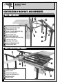
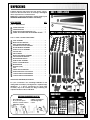
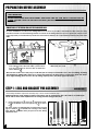
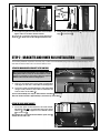
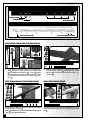
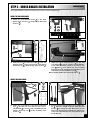
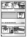
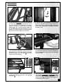
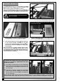
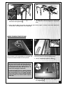
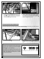
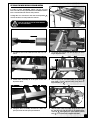
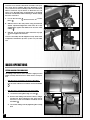
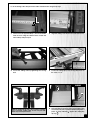
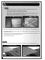
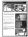
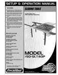
SETUP & OPERATION MANUAL
FEATURES
The table rides on 14 sealed, steel ball
bearing rollers and is supported by architectural grade heavy-duty steel tubing.
Easy to adjust, extruded aluminum miter
fence for accurate miters from 0° to 45°.
Adaptable to virtually all 10-14” table
saws.
SLIDING TABLE
SLIDING TABLE ONLY TABLE SAW SOLD SEPARATELY
New design sliding quick mount bracket
for added cutting capacity. Cut up to 72”*
with the crosscut fence positioned at the
rear. Crosscut or miter up to 49”* with the
fence at the front of the table.
Quick connect mounting bracket allows
for easy removal of the sliding table from
the saw for users with space/storage limitations.
Positive stop rail and locator pin quickly
sets fence for commonly used miter
angles.
SPECIFICATIONS
WORKING FLOOR SPACE
(FRONT TO REAR)
105” (2667 mm)
WORKING FLOOR SPACE
(TO LEFT OR RIGHT OF SAW)
40” (1016 mm)
WIDTH OF SLIDING TABLE
31” (787 mm)
LENGTH OF SLIDING TABLE
30 1/2” (775 mm)
DISTANCE IN FRONT OF BLADE
TO CUT AT 90°*
36” (914 mm)
DISTANCE FROM REAR OF BLADE
TO CUT AT 90°*
62” (1575 mm)
LENGTH OF FENCE
64” (1626 mm)
MODEL
#50-SLT60P
LENGTH OF FENCE WITH EXTENSION STOP
101” (2566 mm)
WEIGHT
140 LBS (64 kg)
* Depending on the positioning of the
mounting bracket on your saw.
VERSION 1_REVISION 1 - November 27/08
© Copyright General® International 11/2008
GENERAL® INTERNATIONAL
8360 Champ-d’Eau, Montreal (Quebec) Canada H1P 1Y3
Telephone (514) 326-1161 • Fax (514) 326-5555 • www.general.ca
THANK YOU
for choosing this Excalibur by General® International model
50-SLT60P Sliding Table. This sliding table has been carefully tested and inspected before shipment and if properly used and maintained, will provide you with years of reliable service. To
ensure optimum performance and trouble-free operation, and to get the most from your investment, please take the time to read this manual before assembling, installing and operating the unit.
The manual’s purpose is to familiarize you with the safe operation, basic function, and features
of this sliding table as well as the set-up, maintenance and identification of its parts and components. This manual is not intended as a substitute for formal woodworking instruction, nor to
offer the user instruction in the craft of woodworking. If you are not sure about the safety of performing a certain operation or procedure, do not proceed until you can confirm, from knowledgeable and qualified sources, that it is safe to do so.
Once you’ve read through these instructions, keep this manual handy for future reference.
Disclaimer: The information and specifications in this
manual pertain to the unit as it was supplied from the
factory at the time of printing. Because we are committed to making constant improvements, General® International reserves the right to make changes to components, parts or features of this unit as deemed necessary,
without prior notice and without obligation to install any
such changes on previously delivered units. Reasonable
care is taken at the factory to ensure that the specifications and information in this manual corresponds with
that of the unit with which it was supplied. However, special orders and “after factory” modifications may render
some or all information in this manual inapplicable to
your machine. Further, as several generations of this
model of sliding table and several versions of this manual may be in circulation, if you own an earlier or later
version of this unit, this manual may not depict your unit
exactly. If you have any doubts or questions contact
your retailer or our support line with the model and serial number of your unit for clarification.
GENERAL® MFG & GENERAL® INTERNATIONAL WARRANTY
All component parts of General® MFG, General® International and Excalibur by General
International ® products are carefully inspected during all stages of production and each unit
is thoroughly inspected upon completion of assembly.
Limited Lifetime Warranty
Because of our commitment to quality and customer satisfaction, General® MFG and
General® International agree to repair or replace any part or component which upon examination, proves to be defective in either workmanship or material to the original purchaser
for the life of the tool. However, the Limited Lifetime Warranty does not cover any product used
for professionnal or commercial production purposes nor for industrial or educational applications. Such cases are covered by our Standard 2-year Limited Warranty only. The Limited
Lifetime Warranty is also subject to the “Conditions and Exceptions” as listed below.
Standard 2-Year Limited Warranty
All products not covered by our lifetime warranty including products used in commercial,
industrial and educational applications are warranted for a period of 2 years (24 months) from
the date of purchase. General® MFG and General® International agree to repair or replace
any part or component which upon examination, proves to be defective in either workmanship or material to the original purchaser during this 2-year warranty period, subject to the
“conditions and exceptions” as listed below.
To file a Claim
To file a claim under our Standard 2-year Limited Warranty or under our Limited Lifetime
Warranty, all defective parts, components or machinery must be returned freight or postage
prepaid to General® International, or to a nearby distributor, repair center or other location
designated by General® International. For further details call our service department at 1-888949-1161 or your local distributor for assistance when filing your claim.
Along with the return of the product being claimed for warranty, a copy of the original proof
of purchase and a “letter of claim” must be included (a warranty claim form can also be used
and can be obtained, upon request, from General® International or an authorized distributor)
clearly stating the model and serial number of the unit (if applicable) and including an explanation of the complaint or presumed defect in material or workmanship.
CONDITIONS AND EXCEPTIONS:
This coverage is extended to the original purchaser only. Prior warranty registration is not
required but documented proof of purchase i.e. a copy of original sales invoice or receipt
showing the date and location of the purchase as well as the purchase price paid, must be
provided at the time of claim.
Warranty does not include failures, breakage or defects deemed after inspection by General®
MFG or General® International to have been directly or indirectly caused by or resulting from;
improper use, or lack of or improper maintenance, misuse or abuse, negligence, accidents,
damage in handling or transport, or normal wear and tear of any generally considered consumable parts or components.
Repairs made without the written consent of General® Internationallwill void all warranty.
TABLE OF CONTENTS
SAFETY RULES . . . . . . . . . . . . . . . . . . . . . . .5
IDENTIFICATION OF MAIN PARTS AND
COMPONENTS . . . . . . . . . . . . . . . . . . . . . . .6
UNPACKING . . . . . . . . . . . . . . . . . . . . . . . .7
List of contents . . . . . . . . . . . . . . . . . . . . . . . . . . . . . .7
Additional requirements for set up . . . . . . . . . . . . .7
FINE TUNING ADJUSTMENTS . . . . . . . . . . . . .17
Leveling the sliding table with the saw table . . . .17
Install the rear outer leg mount . . . . . . . . . . . . . . .17
Setting the sliding table tracking . . . . . . . . . . . . . .18
Squaring the cross cut fence to the blade . . . . .19
Set the 90º stop with the fence in the front
position . . . . . . . . . . . . . . . . . . . . . . . . . . . . . . . . . . .20
Set the 90º stop with the fence in the rear
position . . . . . . . . . . . . . . . . . . . . . . . . . . . . . . . . . . .21
BASIC OPERATIONS . . . . . . . . . . . . . . . . . . .22
PREPARATION BEFORE ASSEMBLY . . . . . . . . . .8
STEP 1 - LEGS AND BRACKET PRE-ASSEMBLY . . .8
STEP 2 - BRACKETS AND INNER RAIL
INSTALLATION . . . . . . . . . . . . . . . . . . . . . . .9
Attach the main mounting bracket to the saw
table . . . . . . . . . . . . . . . . . . . . . . . . . . . . . . . . . . . . . .9
Attach the quick mount bracket . . . . . . . . . . . . . . .9
Attach the rear inner leg mount to the inner
guide rail . . . . . . . . . . . . . . . . . . . . . . . . . . . . . . . . . .10
Attach the inner guide rail to the quick
mount bracket . . . . . . . . . . . . . . . . . . . . . . . . . . . . .10
Install the switch mount bracket . . . . . . . . . . . . . .10
STEP 3 - CROSS BRACES INSTALLATION . . . . .11
Install the rear cross brace . . . . . . . . . . . . . . . . . . .11
Install the cross braces . . . . . . . . . . . . . . . . . . . . . .11
STEP 4 - TABLE AND FENCE INSTALLATION . . . .12
Install the sliding table . . . . . . . . . . . . . . . . . . . . . .12
Bearing adjustments . . . . . . . . . . . . . . . . . . . . . . . .13
Install the angle adjustment rail . . . . . . . . . . . . . .14
Cross cut fence assembly . . . . . . . . . . . . . . . . . . .15
Setting and using the sliding scale . . . . . . . . . . . .22
Check points . . . . . . . . . . . . . . . . . . . . . . . . . . . . . .24
Panel cutting . . . . . . . . . . . . . . . . . . . . . . . . . . . . . .24
Miter cuts . . . . . . . . . . . . . . . . . . . . . . . . . . . . . . . . . .26
USAGE TIPS . . . . . . . . . . . . . . . . . . . . . . . .26
RECOMMENDED OPTIONAL ACCESSORIES . . . .27
PARTS LIST AND DIAGRAMS . . . . . . . . . .28 - 32
CONTACT INFORMATION . . . . . . . . . . . . . . . .34
Rules for Safe Operation
To help ensure safe operation, please take a moment to learn the machine’s applications and limitations,
as well as potential hazards. General International disclaims any real or implied warranty and hold itself
harmless for any injury that may result from the improper use of it’s equipment.
1. Do not operate the saw when tired, distracted, or
under the effects of drugs, alcohol or any medication that impairs reflexes or alertness.
2. The working area should be well lit, clean and free
of debris.
3. Keep children and visitors at a safe distance when
the saw is in operation; do not permit them to
operate the saw.
4. Childproof and tamper proof your shop and all
machinery with locks, master electrical switches
and switch keys, to prevent unauthorized or unsupervised use.
5. Stay alert! Give your work your undivided atten
tion. Even a momentary distraction can lead to serious injury.
6. Fine particulate dust is a carcinogen that can be
hazardous to health. Work in a well-ventilated area
and whenever possible use a dust collector and
wear eye, ear and respiratory protection devices.
7. Do not wear loose clothing, gloves, bracelets, necklaces or other jewelry while the saw is in operation.
Wear protective hair covering to contain long hair
and wear non-slip footwear.
8. Be sure that adjusting wrenches, tools, drinks and
other clutter are removed from the machine and/or
the feed table surface before operating.
9. Keep hands well away from the blade and all moving parts. Use a brush, not hands, to clear away
chips and dust.
10. Be sure that the blade is securely installed and in
proper cutting direction before operation.
11. Be sure the blade has gained full operating speed
before beginning to cut.
12. Always use a clean, properly sharpened blade.
Dirty or dull blades are unsafe and can lead to
accidents.
13. If using a power feeder, stop the feeder before stopping the table saw.
15. Use suitable support when cutting stock that does
not have a flat surface. Always hold stock firmly
against the fence when ripping, or against the miter
gauge when cross-cutting.
16. To minimize risk of injury in the event of workpiece
kickback, never stand directly in-line with the blade
or in the potential kickback path of the work piece.
17. Avoid working from awkward or off balance positions. Do not overreach while cutting; keep both
feet on floor. Never lean over or reach over the
blade and never pull the work piece over the blade
from behind. Use out feed support or have an assistant help when ripping long material.
18. Keep blade guards in place and in working order.
If a guard must be removed for maintenance or
cleaning, be sure it is properly reattached before
using the tool again.
19. Never leave the machine running with the power
on when not in operation.
20. Use of parts and accessories NOT recommended
by GENERAL® INTERNATIONAL may result in equipment malfunction or risk of injury.
21. Never stand on machinery. Serious injury could
result if the tool is tipped over or if the blade is unintentionally contacted.
22. Always disconnect tool from power before servicing
or changing accessories such as blades, or before
performing any maintenance, cleaning or adjustments, or if the machine will be left unattended.
23. Make sure that switch is in "OFF" position before
plugging in the power cord.
24. Make sure the tool is properly grounded. If equipped with a 3-prong plug it should be used with a
three-pole receptacle. Never remove the third
prong.
25. Do not use this sliding table for other than its intended use. If used for other purposes, GENERAL® INTERNATIONAL disclaims any real implied warranty and
holds itself harmless for any injury, which may result
from that use.
14. Do not push or force stock into the blade. The saw
will perform better and more safely when working
at the rate for which it was designed.
5
SLIDING TABLE
50-SLT60P
IDENTIFICATION OF MAIN PARTS AND COMPONENTS
RAIL & BRACE ASSEMBLY
MAIN MOUNTING BRACKET
QUICK MOUNT BRACKET
CROSS BRACE (3X)
FRONT OUTSIDE BRACKET (2X)
REAR CROSS BRACE
INNER GUIDE RAIL
REAR INSIDE BRACKET
FENCE STORAGE BRACKET (2X)
SUPPORT LEG (4X)
LEVELING FOOT (4X)
REAR OUTSIDE BRACKET
OUTER GUIDE RAIL
TABLE & CROSS CUT FENCE ASSEMBLY
CROSS CUT FENCE
MITER CLAMP
SLIDING FLIP-UP STOP
ANGLE ADJUSTMENT RAIL
RETURN HANDLE
SLIDING TABLE
6
UNPACKING
Carefully unpack and remove the unit and its components from the box and check for missing or damaged
items as per the list of contents below.
BOX 1 - FENCE & RAILS
NOTE: Please report any damaged or missing items to your
GENERAL® INTERNATIONAL distributor immediately.
LIST OF CONTENTS
QTY
BOX 1 - FENCE & RAILS
OUTER GUIDE RAIL . . . . . . . . . . . . . . . . . . . . . . . . . . . .1
INNER GUIDE RAIL . . . . . . . . . . . . . . . . . . . . . . . . . . . .1
FENCE WITH FENCE EXTENSION POST . . . . . . . . . . . .1
ANGLE ADJUSTMENT RAIL WITH RETURN HANDLE . . .1
BOX 2 - TABLE & OTHER COMPONENTS
BOX 2 - TABLE & OTHER COMPONENTS
TABLE ASSEMBLY . . . . . . . . . . . . . . . . . . . . . . . . . . . . .1
QUICK MOUNT BRACKET . . . . . . . . . . . . . . . . . . . . . .1
MAIN MOUNTING BRACKET . . . . . . . . . . . . . . . . . . . .1
SLIDING FLIP-UP STOP ASSEMBLY . . . . . . . . . . . . . . . .1
ROLLER BEARING ASSEMBLY . . . . . . . . . . . . . . . . . . . .2
FENCE PIVOT PIN ASSEMBLY . . . . . . . . . . . . . . . . . . . .1
SUPPORT LEG . . . . . . . . . . . . . . . . . . . . . . . . . . . . . . . .4
CROSS BRACE . . . . . . . . . . . . . . . . . . . . . . . . . . . . . . .3
REAR CROSS BRACE ASSEMBLY . . . . . . . . . . . . . . . . .1
SAW MOUNTING BRACKET . . . . . . . . . . . . . . . . . . . . .1
REAR BRACKET MOUNT . . . . . . . . . . . . . . . . . . . . . . . .1
MITER CLAMP ASSEMBLY . . . . . . . . . . . . . . . . . . . . . . .1
FRONT OUTSIDE BRACKET . . . . . . . . . . . . . . . . . . . . . .2
REAR BRACKET . . . . . . . . . . . . . . . . . . . . . . . . . . . . . . .2
RATCHET LEVER . . . . . . . . . . . . . . . . . . . . . . . . . . . . . .1
T-NUT . . . . . . . . . . . . . . . . . . . . . . . . . . . . . . . . . . . . . . .1
SWITCH MOUNT BRACKET . . . . . . . . . . . . . . . . . . . . . .1
FENCE EXTENSION STOP MOUNT . . . . . . . . . . . . . . . .1
5 MM T-HANDLE ALLEN WRENCH . . . . . . . . . . . . . . . .1
6 MM T-HANDLE ALLEN WRENCH . . . . . . . . . . . . . . . .1
MOUNTING HARDWARE/FASTENER KIT
For your convenience, the mounting hardware for the
sliding table assembly is packaged into 4 separate bags
identified 1, 2, 3 and 4, respectively. For each main
assembly step in this manual, the bag containing the
required hardware will be indicated.
HARDWARE
ADDITIONAL REQUIREMENTS FOR SET UP
• Drill & drill bits
• 10/13/14 mm open
end & or socket wrench
• Machinist square
BAG 1
BAG 2
BAG 3
BAG 4
• Phillips Screwdriver
• Measuring tape
• Level
7
PREPARATION BEFORE ASSEMBLY
VERY IMPORTANT!
BEFORE PROCEEDING WITH THE ASSEMBLY STEPS MAKE SURE THE SAW TABLE IS LEVELED WITH THE
FLOOR, PLACING A LEVEL ON THE TABLE. USE SHIMS (OR LEVELING FEET IF APPLICABLE) FOR LEVELING
IF NEEDED.
REMOVE TABLE LEFT EXTENSION WING, RIP FENCE AND GUIDE RAILS
For most installations, in order for the sliding table to be as close as possible to the blade the table extension wing
must be removed. To avoid interfering with the movement of the sliding table, the rip fence guide rails will also need
to be temporarily removed and may need to be shortened so that they do not protrude beyond the end of the main
table.
1. Make a reference mark on the rip fence guide rails
even with the end of the main table (not the extension wing
and then remove and set aside the
fence and rails .
2. Remove the left extension wing
table and set it aside.
from the main
Note: Do not cut the fence rails just yet - wait until you are ready to re-install the fence after assembling, installing
and aligning the sliding table. Some fence systems may allow you to simply slide or re-mount the guide rails further
to the right, allowing you to increase the rip cutting capacity of the saw to the right of the blade.
STEP 1 - LEGS AND BRACKET PRE-ASSEMBLY
HARDWARE BAG 1*
*All mounting hardware required for Assembly Step 1 can be found in hardware bag 1.
NOTE: Adjustments made during the initial set-up phase may be approximate. Once the table is assembled you
will be able to make minor adjustments for leveling and fine tuning at that time.
1. Install a leveling foot , a hex nut , and a flat washer
to the bottom of all four support legs , as shown
in .
Tip: Leave a space of approximately 1" between the feet and
legs as shown in
to facilitate the leveling of the sliding
table with the saw table when you proceed to fine tuning
adjustments later.
1”
8
CLOSE UP
2. Fit a support leg into the four brackets as shown then
tighten with two hex bolts and flat washers.
3. Install a fence storage bracket
legs
as shown in .
onto the two front
Tip: Select the second hole from the top of the bracket as
shown in
to allow room for fine tuning adjustments later.
STEP 2 - BRACKETS AND INNER RAIL INSTALLATION
HARDWARE BAG 2*
*All mounting hardware required for Assembly Step 2 can be found in hardware bag 2. After having completed Step 2, six hex
bolts and six washers will be left over. Put them aside for now.
ATTACH THE MAIN MOUNTING BRACKET TO THE SAW TABLE
Note: Four hex bolts and flat washers are supplied with your
Sliding Table. However, if they do not thread into the mounting holes on your table, use the fasteners that were supplied
with the saw to hold the extension wing in place.
1. Check to see which holes on the main mounting bracket aligns on the saw’s main table mounting holes.
1/8”
2. Secure the main mounting bracket to the main table
using as many fasteners as possible, at minimum, the
rear two holes of the table .
Tip: For added stability, holes may be drilled into the saw table
if necessary.
Note: The bracket should be approximately 1/8” from the top of the table
.
ATTACH THE QUICK MOUNT BRACKET
1. Secure the quick mount bracket to the main mounting bracket with ALL 4 socket head cap screws and 4
washers , using the supplied 6 mm t-handle wrench
, as shown in .
Note: Position the quick mount bracket with the square holes
towards the rear of the saw.
9
INNER RAIL UNDERSIDE VIEW - THREADED HOLES
REAR INNER LEG MOUNT
QUICK MOUNT BRACKET
SWITCH MOUNT BRACKET
REAR BRACKET MOUNT
INNER RAIL SIDE VIEW - ACCESS HOLES
FASTENER ACCESS HOLES (X6)
SLIDING TABLE BEARING ACCESS HOLES
ATTACH THE REAR INNER LEG MOUNT TO THE INNER GUIDE RAIL
INNER REAR LEG MOUNT
1. Using the quick mount bracket as a height gauge , adjust the height of the rear inner leg mount
by finding the hole that comes closest
and/or
by adjusting the leveling foot , until the top of the
rear inner bracket is even with the quick mount bracket .
2. Attach the rear leg mount to the inner rail using 2
hex bolts and 2 washers , aligning the leg mount
with the back two threaded holes in the rail , as
shown in .
ATTACH THE INNER GUIDE RAIL TO THE QUICK MOUNT BRACKET
INSTALL THE SWITCH MOUNT BRACKET
RAIL UNDERSIDE VIEW
QUICK MOUNT BRACKET
Attach the inner rail to the quick mount bracket using 4
hex bolts and 4 washers .
Note: Verify that the inner rail is somewhat parallel with the saw
table
before tightening the bolts.
10
Final installation shown for clarity only
SWITCH MOUNT BRACKET
Install the switch mount bracket on the front end of the
inner rail as shown in , using 2 hex bolts and 2 washers .
STEP 3 - CROSS BRACES INSTALLATION
HARDWARE BAG 3*
All mounting hardware required for Assembly Step 3 can be found in hardware bag 3.
INSTALL THE REAR CROSS BRACE
1. Attach the rear bracket mount
to the inner
guide rail as shown in , using two hex bolts and
washers .
REAR BRACKET MOUNT
2. Attach the rear cross brace assembly
to the rear
bracket mount , using one hex bolt, 2 flat washers
and a lock nut
in the assembly order shown in .
3. Attach the saw mounting bracket
to the rear
cross brace
as shown, using the same hardware,
in the same assembly order as in previous step
(see
and
), then attach the saw mounting
bracket to the saw, using the same hardware as for
rear bracket mount installation (see ).
Note: If needed, drill two holes in your saw cabinet
.
INSTALL THE CROSS BRACES
4. Attach two cross braces to the quick mount bracket
and the last cross brace to the rear inside bracket
as shown, using 6 shoulder bolts, flat
washers and cap nuts
in the assembly order
shown in .
5. Using the quick mount bracket as a height gauge
, adjust the height of the two front outer leg
mounts
by finding the hole that comes closest
and/or by adjusting their leveling foot, until the top
of the front outer brackets are even with the quick
mount bracket.
11
Final installation shown for clarity only
7. Attach the two front outside leg mounts
to the
cross braces as shown, using 6 shoulder bolts, flat
washers and cap nuts .
8. Attach the outer rail to the leg mounts (with the
wide polished surface
closest to the table saw)
as shown, using 4 hex bolts and washers
from
hardware bag 2.
Note: The rear outer leg mount
will be installed later, once the sliding table has
been leveled with the saw table in the section “FINE TUNING ADJUSTMENTS”.
The 2 hex bolts and washers remaining from hardware bag 2 will be used for this
later.
STEP 4 - TABLE AND FENCE INSTALLATION
HARDWARE BAG 4*
*All mounting hardware required for Assembly Step 4 can be found in hardware bag 4.
INSTALL THE SLIDING TABLE
FRONT VIEW
1. Carefully slide the table onto the rails
with the
bearings/scrapers in the bearing guide channel as
shown in .
12
2. Screw the table stops
into the threaded holes at
each end of the outer guide rail as show in .
BEARING ADJUSTMENTS
CLOSE UP
PULL BACK TO
LOCK
3. To eliminate the lateral play between the table and
the outer rail, release the locking bolts on the
eccentric adjusters from underside of the table.
Using a 3/4” socket or wrench turn the eccentric
adjusters
to pre - load the bearings against the
rail. DO NOT OVER LOAD the bearings to the rail.
Tighten the eccentric adjusters locking bolts making sure the eccentric adjusters do not move.
4. The brake lever is also mounted on an eccentric
adjuster. If needed, turn the eccentric adjuster so
that the brake lever prevents the table from sliding
when in the locked position. Pull back towards the
operator to lock.
5. To set and maintain even spacing between the
inner rail and the sliding table, insert wood or cardboard shims (1/8”- 3/16” thick) between the inner
rail and the edge of the saw table
at the front
and the rear of the table .
6. While leaning against the outside of the table to pinch
the shims in place tighten the outer rail mounting bolts
on the outer brackets using a 12 mm socket and then
remove the shims.
TOP VIEW
7. Using the slotted holes on the outer horizontal face
of the sliding table
install the 2 roller bearing
assemblies .
8. Adjust the positioning of the bearing brackets, in or
out, along the slotted holes
in the table to bring
the bracket as close to the outside edge of the rail,
without touching . Then tighten the nuts
to lock
the bearing brackets in place.
13
9. Adjust the height of the bearings in the slotted
hole
in their bracket so that each bearing touches the bottom edge of the guide rail, then tighten the nuts
to lock the bearings in place.
10. To eliminate the vertical play between the table and
the inner rail, using the 6 mm "T" handle wrench supplied , locate and release the locking bolts on the eccentric adjusters (access through holes in inner rail
). Using a 3/4” socket or wrench , turn the eccentric adjusters to pre-load the bearings against the
inner rail. DO NOT OVER LOAD the bearings to the rail.
Tighten the eccentric adjuster locking bolts making
sure the eccentric adjusters do not move.
11. Loosen the nut
on the switch mount bracket bearing then adjust the height of the bearing in its slotted hole
until it just touches the underside of the
sliding table, then tighten the nut to lock the bearing in place.
INSTALL THE ANGLE ADJUSTMENT RAIL
1. Attach the angle adjustment rail to the outside
edge of the sliding table
by sliding the t-nuts
into the T-slot in the adjustment rail
and roughly
center the rail (equal distance front to back) on the
table .
14
2. With a square or a straightedge, verify that the angle adjustment rail is leveled with the table
at
both ends of the rail. Then tighten the two t-nut /hex
head bolt assemblies
to secure the rail to the
table.
RAIL UNDERSIDE VIEW
3. Thread a t-nut
on to one of the ratchet levers .
Then slide the t-nut into the t-track
, and locate
the hole in the underside of the angle adjustment
rail .
4. Thread a ratchet lever
onto the fence pivot
brackets
at each end of the table.
Note: This ratchet lever is used to secure the return handle.
CROSS CUT FENCE ASSEMBLY
1. Sit the cross cut fence face down on the front* of
the sliding table
with holes
facing upward.
2. Insert the plastic washer on the fence pivot post
.
*For directional clarity "front" is used to refer to the operators side of the saw.
3. Insert the t-nut into the t-slot on the right end of the
fence (closest to the saw) , then slide the pivot post
approximately 12" onto the fence , and secure it
with the ratchet lever .
12”
15
4. Side the t-nut
on the miter clamp
into the t-slot
approximately 2' from the opposite end of the
fence
.
5. Fit the pivot post into the pivot post bracket
.
Note: The pivot post should protrude an equal distance
from the top and bottom of its mounting bracket
.
Flush here
6. Slide the mitre clamp assembly along the fence
until the t-nut lines up with the t-slot on the angle
adjustment rail . If needed, adjust the height of
the mitre clamp post
so it is flush with the bottom
of the mitre clamp bracket
.
7. Remove the fence extension post from the end of
the fence . Slide the fence extension stop mount
on to the post and re-install the post in the same
end of the fence .
8. Install the two thumbscrews
into the holes in the
front face of the cross cut fence.
The cross cut fence may be stored on the fence storage
brackets as shown above.
Note: The thumbscrew is used to lock the fence extension
post in place.
16
FINE TUNING ADJUSTMENTS
To ensure the ability to make square and accurate repeat cuts the following fine tuning adjustment procedures
should be performed after completing the assembly steps.
VERY IMPORTANT!
THE FOLLOWING ADJUSTMENTS WILL PROVIDE ACCURACY ONLY IF YOUR SAW TABLE IS LEVELED WITH THE
FLOOR. USE SHIMS (OR LEVELING FEET IF IT HAS SOME) FOR LEVELING IF NEEDED.
LEVELING THE SLIDING TABLE WITH THE SAW TABLE
1. Using a level, verify that the sliding table is leveled
with the saw table .
2. If needed adjust the leveling feet on the support
legs
. The height of the main mounting bracket
may also need to be adjusted .
Once the sliding table has been leveled with the saw table, you can proceed to rear outer leg mount installation
as follows.
INSTALL THE REAR OUTER LEG MOUNT
RAIL UNDERSIDE VIEW
1. Place the rear outside leg mount
next to the
outside guide rail. The top of the bracket should be
at the same height as the bottom of the guide rail.
If not, find the hole that comes closest and, if needed, fine tune with the leveling foot.
2. Attach the rear outside leg mount under the outside
guide rail as shown in
using the two remaing
hex bolts and washers from hardware bag 2 .
17
SETTING THE SLIDING TABLE TRACKING
The sliding table must be set to run parallel to the blade
(and not the mitre slot ) .Verify and, if needed, set the
table tracking parallel to the blade as follows:
Note: For the following step you will need a straightedge (a
minimum of 30" long and preferably as long as possible). If
you don’t own one, you can always use your saw rip fence.
TURN OFF AND UNPLUG THE SAW BEFORE PERFORMING ANY ADJUSTMENTS.
Note: For the following step, the cross cut fence must be
set at the front of the table.
1/4”
1. Raise the table saws blade to its maximum and place
the straightedge (or rip fence) against the blade.
2. Bring the sliding tape measure slide to approximately
1/4" from your straightedge
3. Slowly slide the table front to back
while observing
for any distance/parallel variations from the tape
measure slide to the straightedge (or rip fence) , taking care not to bump or dislodge the straightedge
from the blade.
Note: If you observe no parallel variations from the tape
measure slide to the straightedge, then the table is in fact
already tracking parallel to the blade and will require no further adjustment. Proceed to the next adjustment: “Squaring
the Cross Cut Fence to the Blade”.
To eliminate the variation and set the table tracking
parallel to the straightedge, adjustments to the outer
rail will be required.
> 1/4”
< 1/4”
If the table is tracking away from the straightedge
(front to back) then the trailing end of the outer rail
will need to be moved slightly in towards the saw
(see next step).
If the table is tracking in towards the straightedge
(front to back) then the leading end of the outer
rail will need to be moved slightly in towards the
saw (see next step).
Note: As you move either end of the outer rail in towards the saw make sure to maintain a minimum 1/16" gap between
the table and the outside edge of the inner rail (see shims reference – step #5 of “Install the sliding table”, on page 13.
18
RAIL UNDERSIDE VIEW
4. To adjust the outer rail, loosen the 2 bolts
and center outer leg bracket .
on the front
5. Manually adjust either the front or rear end of the outer
rail towards the saw then retighten the leg bracket
bolts.
6. Slowly slide the table front to back and verify the table tracking again. If needed, make further adjustments
until the table is tracking parallel to the straightedge.
SQUARING THE CROSS CUT FENCE TO THE BLADE
FENCE IN FRONT POSITION-
90°
In order to make repeatable square cuts the crosscut
fence must be set 90° perpendicular to the blade with
the fence mounted in both front & rear positions.
Verify and, if needed, adjust the alignment of the cross
cut fence as follows for front mounted position.
1. Place a straightedge against the blade
.
Note: The accuracy of this adjustment will only be
as good as the accuracy of the squaring tool used.
A typical construction style “framing square”
is
not considered a precision tool and is not adequate for fine tuning type adjustments.
If you do not already own one, consider contacting
your local woodworking or machinist supply distributor and investing in a set of quality machinist
squares that can be used for fine tuning and adjustments for virtually every machine found in a typical
wood shop.
2. Place one edge of a machinists square
the straightedge .
flush to
19
CLOSE UP
3. Loosen the miter clamp
and adjust the cross cut
fence
to the perpendicular face of your machinists square . Then secure the cross cut fence in
position by tightening the miter clamp.
4. Adjust the sliding angle indicator (degree scale) by
loosening the lock bolt
and manually aligning
it to “0” with the front face of the cross cut fence
and then re-tighten the lock bolt.
SET THE 90º STOP WITH THE FENCE IN THE FRONT POSITION
The 90° stop can now be set to allow the cross cut fence to be brought back perpendicular to the blade whenever
needed and without having to further realign the fence each time. To do this:
1. Loosen the 3 hex bolts
.
Once the 90º stop has been set, the positive stop pin
can be used to locate the other holes in the positive
stop rail, which corresponds to the other commonly
used angles: 15º, 22.5º, 30º and 45º.
To manually set an angle, first loosen the miter clamp
locking levers, then slide the left end of the cross-cut
fence along the angle indicator rail to the desired
angle, then retighten the locking levers to securely
lock the fence in position.
20
2. Slide the positive stop rail
until the positive stop
pin
locates the 90° hole
, then retighten the
bolts.
45°
30° 22.5° 15°
90°
SET THE 90º STOP WITH THE FENCE IN THE REAR POSITION
In order to make repeatable square cuts the crosscut
fence must be set 90° perpendicular to the blade with the
fence mounted in both front & rear positions.
To align the cross cut fence in the rear mount position
reverse the fence to rear position as follows.
,
TURN OFF AND UNPLUG THE SAW BEFORE PERFORMING ANY ADJUSTMENTS.
1. If installed, remove the extension from the cross-cut
fence.
2. Loosen the miter clamp and slide the fence off of the
angle adjustment rail.
12”
3. Lift the fence assembly off of the pivot mount and
lay it face down.
4. Slide the pivot post out of the T-track on the fence
and install it on the opposite side of the fence to
approximately 12”, .
VIEW FROM REAR
5. Swing the fence assembly around 180° and fit the
pivot post into the rear pivot post bracket.
6. Slide the miter clamp assembly along the fence until
the t-nut lines up with the t-slot on the angle adjustment rail
, then tighten the pivot bracket ratchet
lever
to secure the fence against the table.
21
Once the cross cut fence has been reversed to rear position, verify and, if needed, adjust the alignment of the
cross cut fence for rear mounted position. You will then be
able to set the 90° stop as follows, to allow the cross cut
fence to be brought back perpendicular to the blade
whenever needed and without having to further realign
the fence each time.
1. Loosen the hex bolt
block
.
and remove the 90° locator
2. With the fence in the rear position, using a machinists
square, repeat the alignment of the fence 90° to the
straightedge against the blade, then lock the miter
clamp
.
3. Slide the 90° locator block until it meets the stop pin
, then re-tighten the hex bolt.
Once the assembly and all alignment steps have been
completed, reinstall the rip fence system on your table
saw.
BASIC OPERATIONS
SETTING AND USING THE SLIDING SCALE
The sliding scale can be set to read left to right (from the
blade onward) with the fence in either front or rear position.
•
With the fence mounted to the front of the table:
Use the scale with the low numbers next to the blade
;
•
With the fence mounted to the rear of the table:
1. Loosen the locking bolt using a 10 mm
.
2. Remove the sliding scale from the fence, swing it
around 180° then re-install it in the same end of
the fence so the low numbers will still be next to
the blade
.
3. Secure the sliding scale by tightening the locking
bolt.
22
CLOSE UP
To set the sliding scale and permit accurate measurements using the flip stop:
1/4”
1. Set the fence to approximately 1/4" from the blade
and secure it using the ratchet levers of both the
miter clamp and pivot post.
2. Align the sliding scale flush to the end of the fence.
10”
3. Secure the sliding scale by tightening the locking
bolt.
4. Position the sliding flip-up stop at any dimension on
the scale, i.e. 10”.
CLOSE UP
NOTE: The sliding flip-up stop is also reversible, allowing
you to orient the leading edge to best suit your work
habits or personal preferences.
5. Draw the table to the front of the saw, providing space between the fence and the blade and place a
piece of scrap material
against the sliding flipup stop .
23
VERIFY ALL FOLLOWING CHECK POINTS BEFORE TURNING ON THE SAW. FAILURE TO COMPLY CAN RESULT IN SERIOUS INJURIES.
CHECK POINTS
•
Make sure that the arbor nut is secure and that the blade is firmly tightened snug on the arbor.
•
Check that the blade angle and height lock knobs are tight.
•
While using the saw, be sure to wear safety glasses at all times.
•
Make sure that the blade guard/splitter assembly is properly installed and aligned with the
blade, and that the anti-kickback pawls are functioning.
•
Slide table front to back to make sure the fence completely clears the blade without touching.
DO
DO NOT
6. Turn on the saw and process the cut ensuring that the workpiece is held tight to the fence and against the stop.
7. To obtain an accurate dimension from the flip stop to the blade, measure the cut workpiece with a separate
tape measure or scale.
8. Transfer this accurate dimension to the sliding scale. To do this, flip up the stop and adjust the sliding scale, aligning the dimension to the leading edge of the flip stop.
9. Lock the sliding scale in place.
PANEL CUTTING
With the cross-cut fence mounted on the rear of the table (rear position), you can cut a maximum cross cut of :
53"* while clearing the blade
* Depending on the positioning of the quick mount bracket on your saw.
24
or up to 62"* without clearing the blade
DO NOT USE RIP FENCE AS A GUIDE OR WORKPIECE STOP WHEN OPERATING THE SLIDING TABLE. TO AVOID POTENTIAL OF
WORKPIECE BINDING WHICH WILL CAUSE KICKBACK, REMOVE THE RIP FENCE FROM THE SAW COMPLETELY.
FENCE IN REAR POSITION
1. Set the cross-cut fence to the rear of the sliding
table (Maximum capacity position).
2. Loosen the two ratchet levers
.
3. Slide the cross-cut fence to within 1/4" of the blade
, then tighten the ratchet levers to secure the
cross-cut fence so it does not move during the cut.
4. Draw the sliding table fully to the front of the saw.
1/4”
5. Load the panel onto the sliding table.
6. Adjust the sliding extension and/or flip stop if needed.
7. With the panel flush to the cross-cut fence, align the
cut line
on the panel with the blade.
Note: For repeat cuts, set the flip stop against the opposite
end of the panel and lock it in place.
8. Turn on the saw.
9.
Keeping a firm forward pressure against the panel
to hold it flush to the fence, walk the panel
through the cut.
Tip: The table return handle
can be used to help maintain pressure on the workpiece against the fence as your
push it through the cut.
25
MITER CUTS
FENCE IN FRONT POSITION
With the cross-cut fence positioned at the front of the
table (front position), you can cut a maximum of 36"*
and make miter cuts from 0° to 45°.
* Depending on the positioning of the quick mount bracket
on your saw.
NOTE: To reposition cutting capacity, slide the quick
mount bracket towards the front of the saw. See the
explanatory note at the bottom of this page.
Loosen the miter clamp locking levers , then slide the
left end of the cross-cut fence along the angle indicator rail to the desired angle
and retighten the locking levers to securely lock the fence in position.
To set commonly used angles: 15º, 22.5º, 30º, 45º
and 90º, loosen the miter clamp locking levers and
position the fence in the vicinity of the desired angle. Compress the stop pin
until it seats in the hole
then tighten the miter clamp locking levers.
USAGE TIPS
The two slots in the quick mount bracket
tioning the cut capacities of this unit.
are for reposi-
For maximum stability, use all four socket head cap screws.
26
The sliding table can be detached from the saw and put
aside
,simply by unscrewing the 4 cap screws which
secure the quick mount bracket to the main mounting
bracket
and by detaching the rear cross brace from
the saw mounting bracket
.
RECOMMENDED OPTIONAL ACCESSORIES
Here are some of the optional accessories available from your local General International dealer.
For more information about our products, please visit our website at www.general.ca
SLIDING FLIP-UP WORKSTOP
#50-EXSTOP
HOLD DOWN CLAMP
#50-EXHDC
Sliding flip stop for cross cut
fence on Excalibur sliding tables. Fits in the t-slot of the cross
cut fence on your Excalibur sliding table. For applications
where multiple repeat cuts are
required, use several stops positioned where needed and flip
up out of the way when not
required.
Hold down clamp for
Excalibur sliding tables.
Holds the workpiece
down for consistent cuts
and improved accuracy with your Excalibur
sliding table.
Notes
27
28
76
71
40
40
71
67
40
71
55
71
68
69
71
40
51
52
52
54
53
51
53
76
71
40
40
71
67
40
71
55
71
68
69
71
40
49
67
71
40
40
71
14
40
71
73
10
17
18
71
45
56
40
71
70
68
69
71
40
46
57
47
81
10
48
9
77
77
52
51
53
77
72
74
71
92
54
71
77
60
71
78
93
71
40
79
54
59
49
100
75
40
71
40
92
71
93
71
52
51
53
101
68
69
71
67
71
40
40
71
SUPPORT SYSTEM
1
2
10
11
5
7
6
13
10
17
18
6
26
11
15
12
10
9
97
20
9
11
97
25
10
18
9
10
8
13
17
19
97
6
13
13
10
21
16
18
10
11
4
3
7
22
10
9
M
13
98
10
23
15
8
9
19
99
19
25
18
8
26
10
12
17
18
8
13
19
96
10
9
10
10
18
18
17
24
17
10
18
9
90
19
17
10
10
8
96
17
18
58
10
7
19
23
10
22
TABLE ASSEMBLY
29
30
35
85
91
89
32
84
83
82
33
94
102
88
31
80
95
38
27
6
7
6
28
30
41
32
39
34
29
86
62
M
50
33
36
61
37
63
38
87
6
6
65
13
63
66
64
29
44
43
42
CROSS CUT FENCE
PARTS LIST 50-SLT60P
REF. N0.
PART N0.
DESCRIPTION
SPECIFICATION
QTY
1
2
3
4
5
6
7
8
9
10
11
12
13
14
15
16
17
18
19
20
21
22
23
24
25
26
27
28
29
30
31
32
33
34
35
36
37
38
39
40
41
42
43
44
45
46
47
48
49
50
51
50SLT60-01
50SLT60-02
50SLT60-03
50SLT60-04
50SLT60P-05
50SLT60-06
50SLT60P-07
50SLT60-08
50SLT60-09
50SLT60P-10
50SLT60-11
50SLT60P-12
50SLT60-13
50SLT60P-14
50SLT60P-15
50SLT60-16
50SLT60-17
50SLT60-18
50SLT60-19
50SLT60-20
50SLT60-21
50SLT60-22
50SLT60-23
50SLT60P-24
50SLT60P-25
50SLT60P-26
50SLT60-27
50SLT60-28
50SLT60-29
50SLT60P-30
50SLT60P-31
50SLT60-32
50SLT60P-33
50SLT60P-34
50SLT60-35
50SLT60-36
50SLT60-37
50SLT60-38
50SLT60-39
50SLT60P-40
50SLT60-41
50SLT60-42L
50SLT60-43
50SLT60-44
50SLT60-45
50SLT60-46
50SLT60-47
50SLT60-48
50SLT60P-49
50SLT60-50
50SLT60-51
PLUG
RETURN HANDLE
SLIDING ANGLE INDICATOR
ANGLE ADJUSTMENT RAIL
POSITIVE STOP RAIL
T-NUT
RATCHET LEVER
ECCENTRIC NUT
LOCK NUT
M6 X 1.0P (10B X 7H)
FLAT WASHER
6.4 X 16X 1.6T
HEX. BOLT
M6 X 1.0P X 16
BRUSH
HEX. BOLT
M6 X 1.0P X 25
HEX. BOLT
M6 X 1.0P X 30
GUIDE BEARING ASSEMBLY
WAVE WASHER
WW-10
BEARING
62002NK
BUSHING
CAP SCREW
M6 X 1.0P X 25
BEARING BRACKET
BRAKE LEVER
PAN HEAD SCREW
M6 X 1.0P X 16
PIVOT POST BRACKET
TABLE
CAP SCREW
M5 X 0.8P X 8
FLAT WASHER
5.2 X 10 X 1.0T
FENCE EXTENSION POST
25.5 X 25.5
FENCE EXTENSION STOP MOUNT
THUMB SCREW
MITER CLAMP ASSEMBLY
SLEEVE
SCREW
M6 X 1.0P X 16
SLIDING BRACKET
FENCE PIVOT PIN ASSEMBLY
SHOULDER BOLT
M6 X P1.0 X 100L
WASHER
Ø28 X Ø19 X 2T
SLIDE PLATE
30 X 52 X 2T
SPRING PIN
6 X 20
PIVOT POST
Ø19 X 85
BOLT
M8 X 1.25P X 16L
EXTENSION BUSHING
Ø12 X Ø6.5 X 25
SCALE
SLIDING SCALE PLATE
14 X 63.5" X 5T
FENCE
49 X 64 X 64"L
OUTER GUIDE RAIL
80 X 40 X 93.5"
STOP RING
Ø13.5 X Ø4.5 X 5T
FLAT WASHER
4.3 X 12 X 1.0T
CAP SCREW
M4 X 0.7P X 12
BRACKET
TAPE
3M VHB F-9473 PC T= 0.25MM
FLAT WASHER
8.5 X 16 X 2.0T
1
1
1
1
1
7
4
6
8
28
7
2
11
1
2
1
14
15
6
2
1
4
2
1
4
4
1
1
2
1
1
2
2
1
1
1
1
4
1
1
1
1
1
1
1
2
2
2
2
1
12
31
PARTS LIST 50-SLT60P
32
REF. N0.
PART N0.
DESCRIPTION
SPECIFICATION
QTY
52
53
54
55
56
57
58
59
60
61
62
63
64
65
66
67
68
69
70
71
72
73
74
75
76
77
78
79
80
81
82
83
84
85
86
87
88
89
90
91
92
93
94
95
96
97
98
99
100
101
102
50SLT60-52
50SLT60-53
50SLT60P-54
50SLT60P-55
50SLT60-56
50SLT60P-57
50SLT60P-58
50SLT60P-59
50SLT60P-60
50SLT60-61
50SLT60-62
50SLT60-63
50-EXSTOP
50SLT60-65
50SLT60-66
50SLT60P-67
50SLT60-68
50SLT60-69
50SLT60P-70
50SLT60P-71
50SLT60P-72
50SLT60P-73
50SLT60P-74
50SLT60P-75
50SLT60P-76
50SLT60P-77
50SLT60P-78
50SLT60P-79
50SLT60P-80
50SLT60P-81
50SLT60P-82
50SLT60P-83
50SLT60P-84
50SLT60P-85
50SLT60P-86
50SLT60P-87
50SLT60P-88
50SLT60P-89
50SLT60P-90
50SLT60P-91
50SLT60P-92
50SLT60P-93
50SLT60P-94
50SLT60P-95
50SLT60P-96
50SLT60P-97
50SLT60P-98
50SLT60P-99
50SLT60P-100
50SLT60P-101
50SLT60P-102
CAP NUT
M8 X 1.25P
CARRIAGE BOLT
5/8 X 1.25P X 16
CROSS BRACE
BRACKET
HEX. BOLT
M8X 1.25P X 20
FLAT WASHER
8.2 X 22 X 3.0T
T-HANDLE ALLEN WRENCH
6 MM
INNER GUIDE RAIL
80 X 40 X 76"
FLAT WASHER
6.3 X 1.3 X 2.0
SHOULDER BOLT
M8 X 1.25P X 65
FLIP STOP
NYLON WASHER
10 X 16 X 1.0T
FLIP STOP ASSEMBLY
SLIDE BLOCK
LOCK NUT
M8 X 1.25P(13B X 9H)
SUPPORT LEG
LEVELING FOOT
M6 X P1.0 X 25
HEX. NUT
M8 X 1.25P(13B X 6.5H)
QUICK MOUNT BRACKET
FLAT WASHER
8.5 X 19 X 2.0T
BEARING GUIDE CHANNEL
SWITCH MOUNT BRACKET
SAW MOUNTING BRACKET
REAR BRACKET MOUNT
STORAGE HOOK
CAP SCREW
M8 X 1.25P X 12
OUTER REAR BRACE
CAP SCREW
M6 X 1.0P X 8L
RATCHET LEVER
MAIN MOUNTING BRACKET
BUTTON
INDEX PIN
SPRING
T-NUT
RATCHET LEVER
RATCHET LEVER
INDEX PIN SEAT
“S” CLIP
STW-6
T-HANDLE ALLEN WRENCH
5 MM
RATCHET LEVER
HEX. BOLT
M8 X 1.25P X 50
LOCK NUT
M8 X 12.5 X 50
TAPE
3M VHB F-9473 PC T= 0.25MM
SLIDE PLATE
CAP SCREW
M8 X 1.25P
FLAT WASHER
6.6 X 13 X 1.0T
90º LOCATOR BLOCK
SCRAPER
REAR BRACE
SHOULDER BOLT
PLASTIC WASHER
P14
12
12
3
2
4
4
1
1
6
1
1
2
1
1
1
4
4
4
1
39
1
1
1
1
2
4
1
6
1
1
1
1
1
1
1
1
1
1
1
1
2
3
1
1
2
6
1
2
1
1
1
NOTES
33
MODEL 50-SLT60P
8360 Champ-d’Eau, Montreal (Quebec) Canada H1P 1Y3
Fax: (514) 326-5565 -
Tel.: (514) 326-1161
Fax: (514) 326-5555 -
Parts & Service /
Order Desk
[email protected]
www.general.ca
IMPORTANT
When ordering replacement parts, always give the model number, serial number of the machine and
part number. Also a brief description of each item and quantity desired.