1
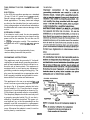
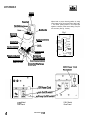
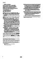
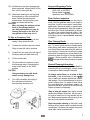
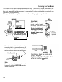
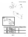
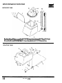
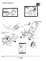
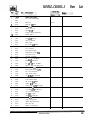
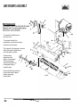
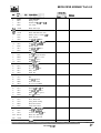
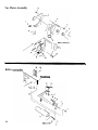
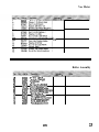
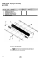
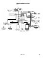
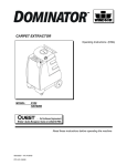
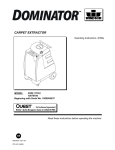
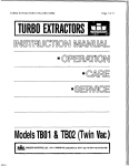
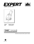
IMPORTANT SAFETY INSTRUCTIONS
When using an electrical appliance, basic precaution must
always be followed, including the following:
READ ALL INSTRUCTIONS BEFORE USING THIS MACHINE.
This machine is for commercial use.
1.
Use only as described in this manual. Use only manufacturer’s recommended attachments.
2.
Use indoors only. Do not use outdoors and do not expose to rain.
3.
Machine can cause a fire when operating near flammable vapors or materials. Do not operate this
machine near flammable fluids, dust or vapors.
4.
Do not pick up flammable fluids, dust or vapors.
5.
Do not vacuum anything that is burning or smoking, such as cigarettes, matches, or hot ashes.
6.
Do not handle the plug or machine with wet hands.
7.
Do not leave the machine unattended. Unplug machine from outlet when in use and before servicing.
8.
Do not unplug machine by pulling on cord. To unplug, grasp the plug, not the cord.
9.
Do not use with damaged cord or plug. Follow all instructions in this manual concerning grounding the
machine.
10. If the machine is not working properly, has been dropped, damaged, left outdoors, or cropped into
water, return it to an Authorized service center.
11. Do not pull or carry by cord, use cord as a handle, close a door on cord, or pull cord around
sharp edges or corners.
12. Do not pull/run machine over cord. Keep cord away from heated surfaces.
13. Do not allow to be used as a toy. Close attention is necessary when used by or near children.
14. Do not operate machine with any openings blocked. Keep openings free of debris that may reduce
airflow.
15. Keep hair, loose clothing, fingers, and all parts of the body away from openings and moving
parts.
16. Use extra caution when cleaning on stairs.
17. Do not use machine as a step.
18. Connect to a properly grounded outlet. See Grounding Instructions.
19. Maintenance and repairs must be done by qualified personnel.
20. “Warning of Potential Injury” . This product contains moving parts. To reduce the risk of injury
unplug machine before servicing.
SAVE THESE INSTRUCTIONS
2
98353 7/l/98
THIS PRODUCT IS FOR COMMERCIAL USE
ONLY.
ELECTRICAL:
In the USA this machine operates on a standard
15 amp 115 volt A.C. power circuit (12OV nominal).
Special voltage models are available for international applications. The amp, hertz and voltage
are listed on the data label found on each machine.
Using voltages above or below those indicated on
the data label will cause serious damage to the
motors.
EXTENSION CORDS:
If an extension cord is used, the wire size must be
the same type and at least one size larger than the
power cord on the machine. Do not use over 50
ft. (15m) of extension cord(s). The machine is
equipped with a 50 ft. (15m) 14/3 SJTW/-A power
cord.
NOTE:
If connected to a circuit protected by fuses,
use time-delay fuses with this proctuct.
WARNING:
ADVERTISSEMENT:
GROUNDING INSTRUCTIONS:
This appliance must be grounded. If it should
malfunction or break down, grounding provides a
path of least resistance for electric current to reduce the risk of electric shock. This appliance is
equipped with a cord having an equipmentgrounding conductor and grounding plug. The
plug must be inserted into an appropriate outlet
that is properly installed and grounded in accordance with all local codes and ordinances.
This appliance is for use on a nominal 120-volt
circuit, and has a grounded plug that looks like
the plug in Fig. A. A temporary adaptor that looks
like the adaptor in Fig. C may be used to connect
this plug to a 2-pole receptacle as shown in Fig.
B if a properly grounded outlet is not available.
The temporary adaptor should be used only until
a properly grounded outlet (Fig. A) can be installed by a qualified electrician. The green colored rigid ear, lug, or the like extending from the
adaptor must be connected to a permanent
ground such as a properly grounded outlet box
cover. Whenever the adaptor is used, it must be
held in place by a metal screw.
98353
PROPER GROUNDING
GROUNDING CONNECTION
Fig. C
3
CONTROLS
Solution
Power Cord
Vat intake Filter/Screen\
Main Handle
Adjust brush to proper cleaning position by using
lever located on the front of the frame. Start at No.
1 “new brush” (black) position. If more carpet pile
agitation is desired, lower brush setting one position at a time. (See fig. 1 below)
Fig. 1
4
Removable
Recoverv \
/
f-
Switches (see below)
Solution Tank , /
>
-HIGH
Accessorv Tool
Water Control Switch
Manifold/Jets
Brush Release Knob
Brush Adiustment
Solution Tank Filter/Screen
(inside Tank)
230V Model
Rear Panel
115V Model
Rear Panel
4
SPD 98353 7/l/98
Preparing the SPIRIT DUAL:
Filling Solution Tank:
For Hard Floor:
1.) Install the optional kit : Vac Shoe Squeegee (p/n
02285). Raise the SPD vac shoe and place the squeegee
assembly over the vac shoe intake. Center the squeegee
on the vac shoe and secure by tightening the two retaining knobs.
1.)
Set dome and recovery tank to the side.
2.)
Use a clean bucket to fill the solution tank
with hot water.
CAUTION: Make sure that the machine is unplugged, switches are turned off and both solution
tanks are empty before beginning brush removal or
replacement.
Now install the hard floor brush. Tilt the machine
2.)
back far enough to grasp the brush. If the carpet brush
is already installed, proceed with step 3 to remove it.
If no brush is installed, proceed with step 4.
3.) To remove brush, pull the brush release knob
back until the brush can be swung out from the housing
and pull the brush off of the drive end.
4.) To replace, align the pulley drive pins on the knob
driver in the housing with the slots in the brush and
slide over the knob driver.
5.) Pull the brush release knob back, align the flat
sides of the brush stub axle in the housing and swing
the brush into place. Then release the knob, returning
to the locked position. Refer to page 17 for parts
outlined in these steps.
6.) Set the water control switch on the front of the
machine to “LOW”. NOTE: If water does not spray
after 5 seconds when the switch is in the “LOW”
position it may be necessary to place it in the
“HIGH” position to start the flow, then return it to
the “LOW” position for hard floor use.
For Carpet:
1.) Remove squeegee from vac shoe by loosening
3.) If necessary add a cleaning concentrate for
use in hot water extractors. Closely follow manufacturer’s instructions found on container. Read
ingredients listed on the container to ensure comCAUTION: Use only the suitable chemicals
listed below. Using incompatible chemicals will
damage the machine. Damages of this type are
not covered under warranty. Carefully read
ingredients on manufacturer’s label before using any product in this machine.
SUITABLE INCOMPATIBLE
CHEMICALSCHEMICALS
Alkalis
Clorox II Bleach*
Defoaming Agents
Detergents
Hydroxides
Oxygen Bleaches
Soaps
Sta-Puf Fabric Softener*
Vinegar
White Monday Bleach*
l
Registered Trademark
Aldehydes
Aromatic Hydrocarbons
Butyls
Carbon Tetrachloride
Clorox*
Chlorinated Bleaches
Chlorinated Hydrocarbons
D-Limonene
Lysol*
Methyls (MEK)
Perchlorethylene(perc)
Phenols
Trichlorethylene
the two retaining knobs.
2.)
Install carpet brush as described above.
3.)
Set the water control switch on the front of the
machine to “HIGH”.
4.)
Place the recovery tank onto the solution tank.
5.)
Set the dome in place on the recovery tank.
Dome must be seated correctly to ensure
proper vacuum seal.
98353
5
SPIRIT
14. When solution tank empties the machine will start
streaking and won’t completely clean the floor.
Turn both switches off, empty the recovery tank,
and refill the solution tank. Use the clear drain
hose on the rear of the solution tank as a sight
gage to determine amount of fluid in tank.
15. Ventilate the room when cleaning has been
completed. Keep all traffic off the floor until it
is thoroughly dry.
1. Fill the solution tank.
2. Move machine to the cleaning area.
3. Lower the brush housing to the floor.
4. Adjust the brush to the desired height.
5. Plug machine into electrical outlet.
6. Release handle by pressing bar with foot.
Push handle forward to lock.
To release handle:
A. Press down with foot.
6. Pull back on handle.
16. When done cleaning for the day bring the machine
to a utility sink and loor drain. Perform the daily
/regular maintenance. Set the recovery tank
aside so solution tank will dry.
7. Press Vac/Pump switch with foot to turn on.
8. Tilt the machine back on rear wheels until brush
is off the floor. Press brush switch with foot to
turn on.
NOTE: Starting the machine with dry brush resting on floor may trip the brush motor circuit
breaker.
9. Squeeze the solution control lever to dispense
cleaning solution.
10. Pull the machine backwards at a steady pace.
Different carpet conditions will determine the
speed required, approximately 25 to 30 feet per
minute (8-9 m). Do not press down on the handle
while cleaning, this will cause the brush housing
to raise slightly and reduce efficiency.
11. Release the solution lever about 12” inches (150
cm) before the end of each pass to ensure all
solution is picked up.
12. Allow each cleaning pass to overlap the previous
pass about 2” inches
13.) cleaning check for foam build-up in recovery tank. hen excessive foam begins to
build up, add a defoaming compound to the
recovery tank according to the Instructions on
the manufacturer’s package. Foam build-up
depends on the type of cleaning concentrate, and
residue remaining carpet.
An overflow of foam from in the recovery tank
into the vacuum intake can damage the vacuummotor. Always be aware of the waste water level
and foam in the recovery tank, es ecially when
using an accessory tool. BEFORE foam or solution is pulled into vac intake empty the recovery
tank.
When not using the machine put the brush in
the storage position. (see daily maintenance on
page 8) Leaving the brush on the floor for long periods of time may ruin It.
Never put defoaming compound in the solution
tank. Damage to pump will result.
NOTE:The vac motor is protected by a circuit
breaker which will only trip under conditions of
abuse, such as an overflow of foam into the
dome. When an overflow does occur the vac
motor must be allowed to dry thoroughly before
continuing work.
1. Remove source of overflow.
2. Run motor to dry.
6
98353
Approved Accessory Tools:
15.) Ventilate the room when cleaning has
been completed. Keep all traffic off the
floor until it is thoroughly dry.
Standard Floor Wands
(SFW, SW, or SW-PRO)
Deluxe Hand Tool (DHT)
Upholstery Hand Tool (UPH3)
16.) When done cleaning for the day bring
the machine to a utility sink and floor
drain. Perform the daily/regular
maintenance. Set the recovery tank
aside so solution tank will dry.
CAUTION:
When not using the machine put the
brush in the storage position.
(see daily maintenance on page 8)
Leaving the brush on the floor for
long periods of time may ruin it.
Floor Surface Inspection:
Determine precisely what areas you are going to
clean. Note the problem areas in the carpet or
hard floor. Look for loose carpet, heavily damaged areas, discolored stains or grease spots
that will require prespotting. Note the carpet or
hard floor type. Check the availability of hot water, drains, and suitable electrical outlets. If the
carpet is loose or worn or there is hard floor surface flaking, have it repaired before attempting
to clean it.
To Use an Accessory Tool:
1.)
Turn the machine completely off and
unplug it from electrical outlet.
2.)
Connect the solution hose to the brass
fitting on lower left side of machine.
3.)
Connect the vac hose to the left side of
the dome (side with white hose cuff).
4.)
Fill the solution tank.
Plan Cleaning Route:
Work from the most remote area towards the
exit. Try not to travel over the cleaned areas
when getting fresh water or dumping old. Furniture should be moved away from the walls before cleaning. If furniture is moved back in place
before floor is completely dry, place plastic or foil
protectors under the legs to prevent possible
staining. When possible use a Windblower
(WB3) and open all windows and doors to speed
drying.
5.)
Plug the machine in and turn on only
the vac/pump switch. Also place the
water control switch in the “HIGH”
position.
CAUTION:
Using accessory tool with brush
switch on may damage floor.
6.)
General Cleaning Information:
Vacuum carpet or sweep hard floor first! Always take the time to thoroughly vacuum carpet
or sweep floor before using the extractor.
On heavily soiled floors, or on areas of high
foot traffic, it may be necessary to use a prespray or traffic lane cleaner applied with a separate sprayer. Do not add presprays to the machine’s solution tank. If a spotter is used, follow
the manufacturer’s instructions exactly as
printed on the label. Spotter left on the floor may
bleach or brown it permanently.
Turn off the machine and unplug it
from electrical outlet before
disconnecting accessory tool.
Shag or deep pile carpets may require several
passes from different directions, but the operator must be careful not to over saturate the carpet. Make several passes without spray to extract as much moisture as possible.
Rinse carpet after cleaning so that sticky soap
build-up will not cause carpet to quickly become
soiled again. Go back over carpet using only
clean warm water in solution tank.
98353
7
Dailv Maintenance:
WARNING OF
POTENTIAL INJURY
These procedures are followed at the end of
each work period to extend the life of the machine.
This product contains moving parts.
To reduce the risk of injury; unplug the
machine before servicing.
1.)
Empty unused cleaning solution by
disconnecting clear hose on back of
machine and pouring into floor drain.
2.)
Inspect and clean solution filter screen
inside tank and vac intake screen
inside dome.
3.)
Flush the system. Fill solution tank
with 1 or 2 gallons (4 - 8 liters) of clean
hot water. With machine over floor
drain turn on vac/pump switch until
solution tank is empty.
4.)
Inspect spray pattern of jets.
Remove jets and rinse if clogged.
5.)
After each use, rinse recovery tank with
fresh water. Periodically inspect the
recovery tank and decontaminate if
necessary, using a Hospital Grade
Virucide or a l-l 0 bleach to water
solution. Waste water should be disposed
of properly.
6.)
Remove any lint or debris from brush.
7.)
Inspect power cord. Remember, this
cord will lay on a damp surface.
Maintenance and repairs must be done
by qualified personnel ONLY.
CAUTION:
Using non-Windsor parts to repair this
machine will void the 6-3-1 warranty.
Warranty information is located on the
back of this manual.
Suggested Service Parts List
DESCRIPTION
PART NUMBER
Belt
Brush Bearing
115V Cord Assembly (USA/Japan)
230V Cord Assembly (Europe)
Dome Assembly
Dome Gasket
Hose Cuff. Short Blue
Hose Cuff. Longer Blue
Hose Cuff, White
Jet Assembly
Jet
Jet Seal
Jet Body w/Seal
Manifold Assembly (No Jets)
Pump Service Kit
Screen/Filter, Dome
Screen/Filter, Solution Tank
Solution Release Cable
Solution Release Lever
115V Switch
230V Switch
Valve
8
11031
09019
23572
23178
28034
35060
27508
27354
27079
44055
44061
44051
44052
54094
47176
34140
73250
27665
51200
72074
72121
84134
Warning:
IMMEDIATELY REPLACE WORN OR
FRAYED POWER CORDS.
8.)
Inspect hoses. Worn or cracked
hoses may cause loss of vac pressure.
9.)
Place the brush in the storage
position. Press back slightly on the
main handle, and place the brush
adjustment lever in the “STORE”position.
For infrequent use or long periods of storage, flush the system with a neutralizing solution
of 1 quart (1 liter) white vinegar mixed with 2 gallons (8 liters) hot water. Flush the system with
clean hot water after neutralizing.
98353
Periodic Maintenance:
These procedures are performed by a
trained service technician. The regularity of
these procedures may depend on the machine's use.
1.)
Flush the system with a special
solution to reduce scaling (alkaline
build-up).
Use acetic acid (white vinegar) or an
anti-browning solution. Mix one quart
acetic acid with 2 gallons (I:8 liters) of
hot water in the solution tank (if an
anti-browning solution is used follow
manufacturer’s instructions). Turn on
the vac/pump switch and allow the
machine to run over a floor drain until
the solution tank is empty
(approximately once a month).
2.)
Inspect hoses and cords, replace as
needed.
3.)
Inspect filter screens, clean or replace
as needed.
4.)
Inspect spray pattern of jets, replace or
clean as needed.
5.)
Check the tension of the solution valve
cable, tighten if necessary.
6.)
Inspect the vac motor, remove any lint
build-up at cooling intake, service
carbon vac motor brushes
(Approximately every 750
operation hours).
7.)
With the machine running, the brush
should rotate freely without rattling or
grinding. Replace bearings if
necessary.
98353
CAUTION:
Do not allow this machine to remain in a
vehicle or area where the temperature
will be below 40°F (4°C). Allowing this
machine to freeze will cause damage not
covered by the 6-3-1 warranty.
CAUTION:
Protect this machine from freezing if it
becomes necessary to store it at temperatures below 40°F (4°C).
Use a methyl hydrate window washer type
anti-freeze; mix a gallon or two (4-8 liters) of
anti-freeze solution, following the manufacturer’s instructions. Add the anti-freeze
solution to the solution tank. With the hoses
in place run the machine until the anti-freeze
begins spraying out (don't empty solution
tank). Vacuum out the remaining antifreeze solution in the solution tank. Disconnect the hoses and empty the recovery bucket. Always allow the unit to return to room
temperature before filling with hot water or
operating.
CAUTION:
Do not use Ethylene Glycol or any
cooling system anti-freezes.
Troubleshooting- Chart
Condition
Corrective Action
No Power To Machine:
Dead electrical circuit breaker in fuse box
Check building circuit breaker.
Faulty power cord
Replace
Power switch failure
Test switch for continuity/Replace if necessary.
Faulty circuit breaker
Test circuit breaker for continuity/Replace if necessary.
Internal wiring problem
With the machine unplugged, check for, and correct, any loose wire
connections inside the machine at the switches and terminal block.
Electrical Shock:
Equipment not grounding
Follow grounding instructions exactly.
Receptacle not grounded
Have an electrician inspect the building’s wiring.
Internal electrical problem
Ensure that the machine’s wiring matches the appropriate wiring diagram.
Check for and correct any loose wire connections. Replace any wires
or components which are short circuiting.
Nuisance Tripping of Circuit Breaker:
Brush “buried” More than 3/8” (1 cm)
Brush is adjusted too low, adjust position using the adjustment control
at the front of machine. Best cleaning results are achieved with a minimal
brush/surface contact of less than 3/8” (1cm).
Dry brush
Turn brush motor and pump switches on with machine tilted rearward
(brush off floor). Lower machine back to carpet slowly.
Faulty circuit breaker
Test circuit breaker for continuity/Replace if necessary.
Mechanical problem
Higher amp draws may indicate a mechanical problem. Find parts which
are not moving freely and repair or replace.
Vacuum Motor Speed Varies or Doesn’t Run:
Worn motor brushes
Replace
Motor worn out
Replace
Faulty switch
Replace
Faulty circuit breaker
Replace
Internal wiring problem
Check for and correct any loose wire connections,
Loss Of Vacuum:
Loose vac dome
Center dome over tank.
Crack in dome or poor joint
Replace or repair using acrylic plastic cement only.
Loosecuffsonvacuum hose
Tighten cuffs (turn counter clockwise).
Damaged Dome Gasket
Replace gasket.
Lint or dirt clogging vacuum intake screen
With power off clean vac intake screen found in dome.
Accessory tool clogged
Clean out tool, ensure free airflow.
Vac hose damaged
Replace
Internal electrical problem
Have a trained service technician inspect and repair the machine.
98353 7/1/97
10
Troubleshooting Chart
Condition
Corrective Action
Accessory Tool Fitting Difficult to Connect:
Corrosion on fitting
Clean with steel wool.
Remove and soak in acetic acid (white vinegar).
Lubricate lightly with silicone base lubricant.
Floor Not Getting Clean:
Severe soil conditions
Make several passes at right angles to each other.
Use a prespray.
Floor Too Wet:
Worn spray jet(s)
Replace spray jets which are producing more than a fine mist.
Floor Not Getting Wet:
Solution filter screen clogged
Clean solution filter screen located inside lower tank near the front.
Spray jet(s) clogged
Clean or replace jets.
Do not use a wire to clean jet.
Damaged jets will cause over-saturation.
Pump not running
Check for and correct any loose wires
Faulty pump
Repair or replace
Solution valve adjustment
Adjust solution valve cable until valve operates when handle is pulled.
Brush Not Turning:
Belt broken
Remove belt cover on right side of machine. Inspect belt.
Replace if necessary.
Faulty switch
Replace.
Faulty circuit breaker
Replace.
Faulty brush motor
If the belt, circuit breaker, and switch have been tested and found to be
in good working order, the brush motor may need to be replaced.
Worn Bearings:
Squeeling or grinding sound in brush housing
Replace bearings.
98353 7/1/97
Servicing the Vac Motor
To access the vac motor first remove the solution tank. There are (2) screws which attach the
vac motor mounting bracket to the chassis. Loosen the clamp to remove the hose. To replace
the motor assembly it will be necessary to remove the (3) screws which attach the motor to the
vac motor mounting bracket.
See page 18 for the complete vac motor and mounting equipment parts list.
Wire
Important:
These brushes wear
quicker as the length
shortens due to increased heat.
FINING:
1
The green ground wire
must attach the motor to
the power cord for safe
operation.
I
See wiring diagram.
I
Spring inside brush
housing will damage
motor if brushes are
allowed to wear away
completely.
If armature commutator is not concentric,
extremely pitted, or grooved the motor will
need to be replaced or sent to a qualified
service center to restore vac performance.
Wire Terminal -
Note:
When replacing carbon vac motor brushes
loosen wire terminal BEFORE removing
screws on bracket.
12
(actual size)
Periodically check the length of the
carbon brushes.
Replace both carbon brushes when
either is less than 3/8” long.
6
Vac Shoe Assembly
Assembly
Reverse
10
11
57047
87074
05016
73181
70190
70057
89061
87008
87016
70088
Nut, l/4-20 Nylock
Washer, 3/8 ID x .OlO Wave
Arm, Vac Shoe Parallel
Spacer, .259 ID x .38x .25
Scr, l/4-20 x 1/2 BHCS
Scr, l/4-20 x 1 .O PHMS
Weight, Vat shoe
Washer. l/4 ID x 1 l/4 OD
Washer: #10 star
Scr, lo-32 x l/2 PHMS
96353 7/l/97
13
RECOVERY & SOLUTION TANKS
RECOVERY TANK
Each tank has a filter screen which protects the machine’s internal parts from damage.
Ensure that these screens are in place and clean before operating the machine.
SOLUTION TANK
14
SPD 98353 8/10/98
RECOVERY & TANK ASSEMBLY Parts List
RECOVERY TANK PARTS LIST;
2
3
4
5
6
7
8
9
10
11
12
13
14
87013
73280
38088
75078
14042
39343
39411
27079
27508
27354
28033
50775
50776
Washer, l/4 Flat
Spacer, 1/4 ID x 3/8 Nylon
Handle, Recovery Tank
Tank, Recovery
Bushing, 1.63 ID Snap
Hose, 1.5 x 34” Vac
Hose, 1.5 x 52” Vac
Cuff, White 1.5 Hose
Cuff, Short Blue Hose
Hose cuff, blue
Dome Asm
Label, Warning Explosion Vert
Label, Warning For Safety
SOLUTION TANK PARTS LIST:
2
3
4
5
6
7
8
9
IO
11
12
13
14
15
16
17
18
19
20
39241
40068
39278
57105
70251
672 12
70189
40027
73864
75249
-
Open
Hose, l/2 Wire Bound x 10”
Open
Hosebarb, 3/8 NPT X l/2 Tee
Hose, 1/2” ID x .09 W
Open
Nut, I/4-20 w/Star Washer
Set Scr, l/4-20 x 1 .O
Open
Reatiner, Hose
Scr, l/4-20 x 5/16 PHMS
Hosebarb, 90x 3/8 MPT x 1/2
Strainer, 3/8 NPT 60 Mesh
Open
Open
Open
Tank, SPR Solution1 15VA 1 OV
Open
Open
22
23
50710
50630
Label, 115V Wiring
Label, Warning
SPD 98353 8/10/98
602449
602449
602449
15
Pump...Manifold...VaIve
Spray Jets
Rinse in hot water or use compressed air to
clean. Nozzles can also be soaked in an acetic
acid solution (white vinegar).
CAUTION:
Do not use
pins or wires to clean
or unclog jets.
Using wires or
pins to unclog
jets may ruin
spray pattern.
6
‘23
24
26
Replace jets that no longer produce a fine
mist spray or over saturate carpet.
16
96353 7/l/97
Pump...Manifold...VaIve
04008
56023
78156
56014
65154
12
13
14
15
16
17
18
19
20
24
25
26
27
28
29
31
32
33
70253
57081
40033
27665
70088
84134
31016
40038
20042
39452
70114
14523
39330
44061
44052
54094
66095
57018
73426
87025
70085
39364
57104
87016
56048
Adaptor, .1/4 MPT x l/4 FPT
Nipple, l/4 MPT x 1.5
Tee, l/4 FPT
Nipple, l/4 Close
Pump, 115V 50 PSI
OPEN
Screw, 10-32 x 1.25 PHMS
Nut, 10-32 Captive J
Hosebarb, l/4 MPT x 3/8 90”
Cable, Solution SPD
Scr, 10-32 x l/2 PHMS
Valve, Solution
Elbow, l/4 NPT Street
Hosebarb, 45 deg 1/4MPT x 3,
Clamp. Hose
Hose: 3/8 x 6” Nylobraid
Scr, #1 0 x 3/4 Polyfast
Bracket, Manifold
Hose, 3/4 vinyl x 5-l/2”
Jet, 11003 Mini-Quick
Jet Body w/Seal, Mini-Quick
Manifold
Plug, l/8 MPT
Nut, 10-24 nvlock
Spring, 2.5 x .43 x .047 Ext
Washer, l/4 Star
Scr, l/4-20 x l/2 PHMS
Hose. l/2 ID Clear x 10”
Nut, 10-32 w/Star Washer
Washer, #10 Star
Nipple, l/4 x 1.75
98353
HANDLE...CHASSIS...SWITCHES
Ground
Arrangement
Vac, Brush & Pump
motor ground wires
See page 4 for panel
configuration
18
SPD 98353 9/18/98
HANDLE,..CHASSIS...SWITCHES
2
3
4
5
6
7
8
9
10
11
12
13
14
15
16
17
18
19
20
21
22
23
24
25
26
27
28
29
30
31
32
33
34
35
36
37
38
39
40
41
42
43
44
45
46
57104
Open
89114
41236
70249
73636
73596
51193
38269
41302
57047
36123
41144
70361
57238
51251
27561
27699
27371
57113
70105
87030
70272
50498
72147
62322
57028
27376
70406
73169
50638
70066
87016
27711
70434
23572
70537
57234
57138
99817
50182
35229
62755
35198
35228
Nut, 10-32 w/Star Washer
Wheel, 10”
Hub Cap, Y8” Shaft
Scr, l/4-20 x 1.25 HHMS
Spacer, 5/16 x 1.2”
Spacer, 5/16 x 1”
Linkage, Handle Adjustment
Handle, SPD II
Housing, Solution Lever
Nut, l/4-20 Nylock
Grip, 9.5” Handle
Hook, Cord
Scr, 10-32 X l/2 PHTR
Nut, 10-24 Joint Connector
Lever, Solution
Clip, Solution Cable
Cable,.06X41.3.0707. SS
Clip, Power Cord
Nut, 5/l6- 18 Nylock
Scr, l/4-20 x 1.75 HHMS
Washer, 318 Nylon Flat
Scr, 3/8 x 3/8 5/l6- 18 SHSB
Label, 15 Amp Time Delay Fuse
Switch, 250V 16(4) rckr SPST
Panel, Electrical Panel 115V
Nut, 10-24 Tinnerman
Clip, Switch retainer
Scr, #lO x l/2 sht metal blk
Strain Relief
Label, Handle Adjust
Scr, 10-32 x 3/4 PHMS
Washer, #lO Ext. Star
Control Asm, 115V SPD (pump)
Scr, 6-32 x 3/8 PHTF
Cord Asm, 115V SJTWI-A 50
Scr, 10-24 truss head pltd
Nut, 3/8- 16 square
Nut, 5/16- 18 jam pltd
Tape, l/32 x 1.0 25A
Label, ETL approval
Gasket, Right Frame Top
Plate, Tray Top
Gasket, 8” Clamp Seal
Gasket, Left Frame Top
SPD 98353 9/18/98
602252
Parts
List
BRUSH DRIVE ASSEMBLY
To access the belt remove
the belt cover.
To replace the belt it is
necessary to loosen the motor
and remove the brush.
The “preset” belt tension is correct
when the motor and belt are
securely back in place.
Check pulley
alignment and
correct if necessary.
The brush pulley
and motor pulley can
be aligned using a
straight edge.
Ensure that both protective
covers are back in place
before operating
the machine.
SPD 98353 7/l/97
BRUSH DRIVE ASSEMBLY Parts List
2
3
4
09019
70078
03089
5A
140080
5B
140081
5c
140156
6
87146
36166
7
8
70190
73181
9
70201
10
11
41296
12
70011
87025
13
14
70020
15
67005
66094
16
17
57123
19A 53093
19B
53173
20
87018
21
70074
22
6407 1
23
36044
24
70363
25
11031
26
57047
27
36050
28
70434
29
36043
30
87013
31
70015
32
64088
33
67094
34
70497
35
29157
36
73767
37
48063
38
27666
39
70562
40
57016
41
70118
42A 140174
42B
140086
42C
140157
Bearing, Brush
Shoulder bolt, 5/16 OD x 3/8 L
Axle, Pulley
Brush, SPD Carpet
Brush, SPD Hard Floor
Brush, SPD Hard Floor (Grit)
Washer, 1/2 ID x 1.0 OD x .06 nyl
Guard, Thread
Scr, l/4-20 x l/2 BHCS
Spacer, .259 ID x .38 x .25
Scr, l/4-20 x 3/4 PHMS
Housing, Brush
Scr, l/4-20 x 5/8 HHCS
Washer, l/4 Star
Scr, l/4-20 x 1/2 HHCS
Rivet, l/8 OD pop wht alum
Pin, Roll l/4 OD x 1.375 L
Nut, l/4-20 Captive
Motor, 115V Brush
Motor, 1OOV l/3 HP W/O TO
Washer, #lO Flat
Scr, 10-32 x l/4 KCP
Pulley, Motor
Guard, belt
Scr, 10-32 x 3/8 PHTR
Belt
Nut, l/4-32 Nylock
Gusset, Belt Guard
Scr, 6-32 x 3/8 PPHTP
Guard, Brush Pulley
Washer, l/4 ID x 5/8 OD
Scr, l/4-20 x 3/4 HHCS
Pulley, 2 l/8 OD 7 groove
Ring, l/2 ext. snap
Scr, 1O-24 x 112 SHCS
Driver, Brush SPD
Spring, Brush retaining
Knob, Brush release
Cable, Brush release
Scr, l/4-20 x 5/8 PHCS pltd.
Nut, 7/8 Dia pushlock
Set Screw, 8-32 x 5/16 KCP
Brush Asm, SPD Carpet
Brush Asm, Hard Floor
Brush Asm, Hard Floor (Grit)
SPD 98353 7/l/97
Vac Motor Assemblv
Roller
Front of frame
22
Vac Motor
Roller Assembly
1
2
3
4
5
6
7
8
9
10
11
12
13
14
15
57022
57085
03027
67082
70018
73178
140077
87030
87013
57047
66073
51247
73040
70363
62397
Nut. 3/8-16 lock
Nut; 3/8- 16 hex jam
Axle, Roller
Roller
Scr, 1/4-20x 1 HHMS
Spacer, Roller bracket
Bracket asm, SPD roller
Washer, 3/8 ID x 3/4 OD nylon
Washer, l/4 ID x 5/8 OD
Nut, l/4-20 lock
Pin, l/l6 x 3/4 cotter
Lever asm, Roller adjustment
Spring, Roller adjustment
Scr, 10-32 x 3/8 PHTF
Plate, Roller adjustment
98353
23
SPIRIT DUAL Squeegee Assembly
To attach to the SPIRIT DUAL...
Raise the SPD vac shoe and install squeegee assembly over
the vac shoe intake. Center the squeegee on the vac shoe and secure by tightening the two retaining knobs.
24
98353
115V SPR WIRING DIAGRAM
98353 7/1/97
25
LIMITED WARRANTY
Windsor Industries, Inc. warrants new machines against defects in material and workmanship
under normal use and service to the original purchaser. The warranty period is subject to the
conditions stated below.
3 YEARS FOR PARTS AND I YEAR FOR SERVICE LABOR
Exceptions: Rotationally molded polyethylene tanks carry a 6 year parts and 1 year service
labor warranty. VERSAMATK models carry a 3 year warranty on brush motors, vacuum
motors, and belts, and a 1 year service labor warranty. SENSOR” models carry a 2 year
warranty on vacuum motors and belts, and a 1 year service labor warranty. Extractor brush
motors, pump motors, pc boards and electronics, vat motors (other than VERSAMATIC” and
SENSOR”), pumps, and FLEXSOLTM diaphragms, all RADIIUSTM, all AXCESSTM and
TITANTM1 carry a 1 year parts and service labor warranty. Propane equipment has a 1 year
parts and service warranty. The Onan” engines have a 3 year manufacturers’ warranty. The
Honda@ engines have a 2 year manufacturers’ warranty. The engine warranty is administered
through the engine manufacturer and must be repaired at an authorized service center.
Normal wear items including, but not limited to, belts, brushes, capacitors, carbon brushes,
casters, clutches, cords, filters, finishes, gaskets, hoses, light bulbs, rectifiers, switches, squeegees, bearings, pulleys, relays, actwating cables, tires and wheels will be warranted for
manufacturing defects for 90 days from the purchase date.
The warranty commences on the purchase date by the original end user from an authorized
Windsor Agent, subject to proof of purchase. The Machine Registration Card must be
completed and returned immediately at the time of purchase. If proof of purchase cannot be
identified, the warranty start date is 90 days after date of sale to an authorized Windsor
distributor. Parts replaced or repaired under warranty are guaranteed for the remainder of the
original warranty period.
90 DAY WARRANTY EXTENSION AVAILABLE
Upon receipt of the Machine Registration Card, Windsor will extend the warranty period an
additional 90 days from the purchase date. Does not include items warranted 90 days for
manufacturing defects.
STATED WARRANTIES ARE IN LIEU OF ALL OTHER WARRANTIES,
EXPRESSED OR IMPLIED.
Any statutory implied warranties, including any warranty of merchantability or fitness for a
particular purpose, are expressly limited to the duration of this written warranty. Windsor will not
be liable for any other damages, including but not limited to indirect or special consequential
damages arising out of or in connection with the furnishing; performance, use or inability to use
the machine. This remedy shall be the exclusive remedy of the buyer.
This warranty shall not apply to: 1 .damage in transit; 2.misuse or abuse(including the use of
incompatible or corrosive chemicals or overloading of capacity): 3. failure due to lack of proper
maintenance and care (including cleaning); 4.any design alterations performed by an
organization not authorized or specified by Windsor; 5batteries and chargers. 6. high pressure
washing. 7.electrical components exposed to moisture.
If difficulty develops during the warranty period, contact the authorized Windsor Agent from
whom the product was purchased. Windsor, Inc. may elect to require the return of components
to validate a claim. Any defective part to be returned must be shipped freight pre-paid to an
authorized Windsor Distributor/Service Center or to the Windsor factory.
USE OF PARTS NOT APPROVED BY WINDSOR, INC.
WILL VOID ALL WARRANTIES.
This warranty is valid only for all products sold after July 1, 1995. A product sold before that
date shall be covered by the limited Warranty in effect at the date of sale to the original
purchaser.