1
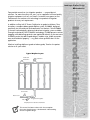
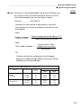
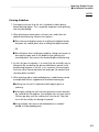
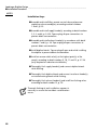
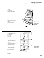
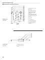
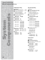
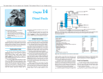
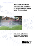
Landscape
Dripline
Design
Landscape Dripline Design_____________________________________________________________
■ Table of Contents
Table of Contents
Introduction . . . . . . . . . . . . . . . . . . . . . . . . . . . . . . . . . . . . . . . . . . . . . . . . . . . . . . . . . . . . .1
i
Terminology . . . . . . . . . . . . . . . . . . . . . . . . . . . . . . . . . . . . . . . . . . . . . . . . . . . . . . . . . . . .2-3
General Design Parameters . . . . . . . . . . . . . . . . . . . . . . . . . . . . . . . . . . . . . . . . . . . . . . . .4-8
Product Selection . . . . . . . . . . . . . . . . . . . . . . . . . . . . . . . . . . . . . . . . . . . . . . . . . . . . . . . .4
Water Availability and Quality . . . . . . . . . . . . . . . . . . . . . . . . . . . . . . . . . . . . . . . . . . . . . . .4
Soil Types and Preparation . . . . . . . . . . . . . . . . . . . . . . . . . . . . . . . . . . . . . . . . . . . . . . . . .5
Plant Material Classification and Planting Layouts . . . . . . . . . . . . . . . . . . . . . . . . . . . . . . . .5
Emitter and Dripline Selection . . . . . . . . . . . . . . . . . . . . . . . . . . . . . . . . . . . . . . . . . . . . . .6
Spacing Guidelines . . . . . . . . . . . . . . . . . . . . . . . . . . . . . . . . . . . . . . . . . . . . . . . . . . . . . . .7
Dripline Placement From Edges . . . . . . . . . . . . . . . . . . . . . . . . . . . . . . . . . . . . . . . . . . . . .7
Designing for Wind . . . . . . . . . . . . . . . . . . . . . . . . . . . . . . . . . . . . . . . . . . . . . . . . . . . . . .7
Designing for Slopes . . . . . . . . . . . . . . . . . . . . . . . . . . . . . . . . . . . . . . . . . . . . . . . . . . . . .8
Designing for Elevation Differences . . . . . . . . . . . . . . . . . . . . . . . . . . . . . . . . . . . . . . . . . .8
Typical Design Procedures . . . . . . . . . . . . . . . . . . . . . . . . . . . . . . . . . . . . . . . . . . . . . . .9-17
Designing a Subsurface System . . . . . . . . . . . . . . . . . . . . . . . . . . . . . . . . . . . . . . . . . . . . . .9
Design Worksheet . . . . . . . . . . . . . . . . . . . . . . . . . . . . . . . . . . . . . . . . . . . . . . . . . . . . . . .10
Typical Design Steps . . . . . . . . . . . . . . . . . . . . . . . . . . . . . . . . . . . . . . . . . . . . . . . . . .10-17
Irrigation Scheduling . . . . . . . . . . . . . . . . . . . . . . . . . . . . . . . . . . . . . . . . . . . . . . . . . . .18-19
Application Rate Formula . . . . . . . . . . . . . . . . . . . . . . . . . . . . . . . . . . . . . . . . . . . . . . . . .18
Water Application Rate Table (In Inches Per Hour) . . . . . . . . . . . . . . . . . . . . . . . . . . . . . .18
Zone Run Time Scheduling Worksheet . . . . . . . . . . . . . . . . . . . . . . . . . . . . . . . . . . . . . . .19
Installation Procedures . . . . . . . . . . . . . . . . . . . . . . . . . . . . . . . . . . . . . . . . . . . . . . . . .20-34
Installation Guidelines . . . . . . . . . . . . . . . . . . . . . . . . . . . . . . . . . . . . . . . . . . . . . . . . . . .20
Planting Guidelines . . . . . . . . . . . . . . . . . . . . . . . . . . . . . . . . . . . . . . . . . . . . . . . . . . . . . .21
Installation Steps . . . . . . . . . . . . . . . . . . . . . . . . . . . . . . . . . . . . . . . . . . . . . . . . . . . . . . . .22
Installation Details . . . . . . . . . . . . . . . . . . . . . . . . . . . . . . . . . . . . . . . . . . . . . . . . . . . .23-34
Routine Preventative Maintenance . . . . . . . . . . . . . . . . . . . . . . . . . . . . . . . . . . . . . . . .35-36
System Inspection . . . . . . . . . . . . . . . . . . . . . . . . . . . . . . . . . . . . . . . . . . . . . . . . . . . . . . .35
Routine Inspection Checklist . . . . . . . . . . . . . . . . . . . . . . . . . . . . . . . . . . . . . . . . . . . . . . .36
Component Maintenance Checklists . . . . . . . . . . . . . . . . . . . . . . . . . . . . . . . . . . . . . . .36-38
Remote Control Valves . . . . . . . . . . . . . . . . . . . . . . . . . . . . . . . . . . . . . . . . . . . . . . . . .36
Filters . . . . . . . . . . . . . . . . . . . . . . . . . . . . . . . . . . . . . . . . . . . . . . . . . . . . . . . . . . . . . .37
Pressure Regulators . . . . . . . . . . . . . . . . . . . . . . . . . . . . . . . . . . . . . . . . . . . . . . . . . . . .37
Dripline . . . . . . . . . . . . . . . . . . . . . . . . . . . . . . . . . . . . . . . . . . . . . . . . . . . . . . . . . . . .37
Flush Caps . . . . . . . . . . . . . . . . . . . . . . . . . . . . . . . . . . . . . . . . . . . . . . . . . . . . . . . . . .38
Troubleshooting Checklists . . . . . . . . . . . . . . . . . . . . . . . . . . . . . . . . . . . . . . . . . . . . . . . .39
Excessively Wet Soil Areas . . . . . . . . . . . . . . . . . . . . . . . . . . . . . . . . . . . . . . . . . . . . . . .39
Excessively Dry Soils . . . . . . . . . . . . . . . . . . . . . . . . . . . . . . . . . . . . . . . . . . . . . . . . . . .39
System Components and Specifications . . . . . . . . . . . . . . . . . . . . . . . . . . . . . . . . . . . .40-43
Drip Tubing . . . . . . . . . . . . . . . . . . . . . . . . . . . . . . . . . . . . . . . . . . . . . . . . . . . . . . . . . . .40
Blank Tubing . . . . . . . . . . . . . . . . . . . . . . . . . . . . . . . . . . . . . . . . . . . . . . . . . . . . . . . . . .40
Filters . . . . . . . . . . . . . . . . . . . . . . . . . . . . . . . . . . . . . . . . . . . . . . . . . . . . . . . . . . . . . . . .40
Check Valve . . . . . . . . . . . . . . . . . . . . . . . . . . . . . . . . . . . . . . . . . . . . . . . . . . . . . . . . . . .40
Flushing Cap . . . . . . . . . . . . . . . . . . . . . . . . . . . . . . . . . . . . . . . . . . . . . . . . . . . . . . . . . .41
Pressure Regulators . . . . . . . . . . . . . . . . . . . . . . . . . . . . . . . . . . . . . . . . . . . . . . . . . . . . . .41
Air Vent/Vacuum Relief Valve . . . . . . . . . . . . . . . . . . . . . . . . . . . . . . . . . . . . . . . . . . . . . .41
Compression Fittings and Adapters . . . . . . . . . . . . . . . . . . . . . . . . . . . . . . . . . . . . . . . . . .41
Coupling . . . . . . . . . . . . . . . . . . . . . . . . . . . . . . . . . . . . . . . . . . . . . . . . . . . . . . . . . . . . .42
Micro Tubing . . . . . . . . . . . . . . . . . . . . . . . . . . . . . . . . . . . . . . . . . . . . . . . . . . . . . . . . . .42
Micro Fittings . . . . . . . . . . . . . . . . . . . . . . . . . . . . . . . . . . . . . . . . . . . . . . . . . . . . . . . . . .42
Micro Fitting Swivel Adapters . . . . . . . . . . . . . . . . . . . . . . . . . . . . . . . . . . . . . . . . . . . . . .42
Dual Goof Plug . . . . . . . . . . . . . . . . . . . . . . . . . . . . . . . . . . . . . . . . . . . . . . . . . . . . . . . .42
Micro Valve . . . . . . . . . . . . . . . . . . . . . . . . . . . . . . . . . . . . . . . . . . . . . . . . . . . . . . . . . . .42
Optional Components . . . . . . . . . . . . . . . . . . . . . . . . . . . . . . . . . . . . . . . . . . . . . . . . . . . .43
Irrigation Controller . . . . . . . . . . . . . . . . . . . . . . . . . . . . . . . . . . . . . . . . . . . . . . . . . . . .43
Fertilizer Injector . . . . . . . . . . . . . . . . . . . . . . . . . . . . . . . . . . . . . . . . . . . . . . . . . . . . . .43
Water Meter . . . . . . . . . . . . . . . . . . . . . . . . . . . . . . . . . . . . . . . . . . . . . . . . . . . . . . . . .43
Soil Moisture Sensor . . . . . . . . . . . . . . . . . . . . . . . . . . . . . . . . . . . . . . . . . . . . . . . . . . .43
_____________________________________________________________Landscape Dripline Design
■ Introduction
Toro provides more than just irrigation products — we provide turf
solutions. For more than forty-five years, we’ve supplied a full line of quality
irrigation equipment to fit any turf need. Customers have grown to trust
Toro because we translate new technology into productive irrigation
products for every turf requirement.
Whether installing dripline at-grade or below-grade, Toro has the perfect
solution to fit your needs.
Typical Dripline Layout
Air/Vacuum
Relief Valve*
Flush Valve
Dripline
Emitter
Control Valve
Introduction
In addition to Drip In® PC Brown Dripline for at-grade installations, Toro
also offers a complete below-grade dripline system, DL2000®, designed
specifically for the residential and commercial turf markets. Toro DL2000®
is the most technologically advanced subsurface irrigation system available.
Through revolutionary ROOTGUARD® technology, DL2000 prevents emitter
clogging while delivering optimal water application directly to the root zone.
DL2000 is perfect for odd-shaped designs, median strips, public recreation
areas and residential property — any place where sprinklers don’t fit the
application.
Water Source
Filter
Pressure Regulator
*Only Required on Subsurface Installations
This manual has been written with the assumption
that users already possess a fundamental understanding
of basic irrigation design.
1
Terminology
Landscape Dripline Design _____________________________________________________________
■ Terminology
2
Application Rate — the rate at which a subsurface grid applies water to a
specific zone, over a given period of time, measured in inches per hour.
Backflow Prevention Device — the device, required by law, on an irrigation
system that prevents water from re-entering the potable water lines once it
flows into the irrigation pipes.
Blackwater — wastewater from toilet, latrine, and agua privy flushing and sinks
used for food preparation or disposal of chemical or chemical-biological
ingredients.
BOD— the abbreviation for “Biochemical Oxygen Demand;” a measure or the
amount of oxygen required to neutralize organic wastes.
Controller — the device that sends timing commands to remote control valves
for actuation.
Design Operating Pressure — the pressure a designer uses to determine spacing
distances and flow for driplines. The design operating pressure is determined
by subtracting estimated friction losses from the static water pressure.
Dynamic Pressure — the pressure reading in a pipeline system with water
flowing.
Effluent Water — any substance, particularly a liquid, that enters the
environment from a point source. Generally refers to wastewater from a
sewage treatment or industrial plant.
Emitter — a device used to control the rate at which water is applied to a
specific area. Emitters are usually injection molded out of chemical-resistant
plastics and come in both inline and online configurations. Toro dripline is
manufactured with factory-installed, inline emitters.
Evapotranspiration — the combined rate at which water evaporates into the
atmosphere and/or is consumed by plants.
Flow — the movement of water through the irrigation piping system.
Flush Cap — a device used to automatically flush sediment and debris from
driplines within a grid. Flushing occurs at the beginning of each irrigation
cycle and ends as soon as the system operation pressure reaches 10 PSI.
Flush Manifold — the end line or pipe in a subsurface grid that connects to all
the driplines. A flush valve and/or cap is installed in the manifold to flush
debris and sediment from the grid during each irrigation cycle.
FPS — the abbreviation for “feet per second;” refers to the velocity of water
in pipes.
Friction Loss — the loss of pressure (force) as water flows through the
piping system.
GPH — the abbreviation for “gallons per hour;” unit of measure for water flow.
GPM — the abbreviation for “gallons per minute;” unit of measure for
water flow.
Greywater —wastewater from washing machines, showers, bathtubs, lavatories
and sinks that are not used for disposal of chemical or chemical-biological
ingredients.
I.D. — the abbreviation for “inside diameter.”
Lateral — the pipe in an irrigation system located downstream from the remote
control valve. Lateral pipes carry water directly to a zone.
Main Line — the pipe in an irrigation system that delivers water from the
backflow prevention device to the remote control valves. This is usually the
largest pipe on the irrigation system, generally under constant pressure and
located upstream from the remote control valves.
_____________________________________________________________Landscape Dripline Design
■ Terminology
NOTES:
Manifold — a group of control valves located together in the same area.
O.D. — the abbreviation for “outside diameter.”
PSI — the abbreviation for “pounds per square inch;” unit of measure for
water pressure.
PVC Pipe — Poly Vinyl Chloride pipe; the most common pipe used in irrigation
systems.
P.O.C. — abbreviation for “point of connection.” This is the location on the
irrigation system where a tap is made for connection of a backflow prevention
device or water meter.
Potable Water — water used for drinking purposes.
Reclaimed Water — domestic wastewater that has been treated to a quality
suitable for a beneficial use and is under the direct control of a
treatment plant.
Remote Control Valve — the component in the irrigation system that regulates
the on/off of water from the main line to the driplines; activated by the
controller.
Service Line — the pipe supplying water from the city water main to the
water meter.
Spacing — the distance between the emitters or the driplines.
Static Water Pressure — the pressure that exists in a piping system when there is
no flow; measured in pounds per square inch (PSI).
Subsurface Grid — a group of parallel, inline driplines that are connected to
supply manifolds and flush manifolds.
Supply Manifold — the pipe connected to the remote control valves that
supplies water to the driplines within a subsurface grid.
Surge — the build-up of water pressure in a piping system due to certain
characteristics of the pipe, valves and flow.
TDS — the abbreviation for “total dissolved solids.” The sum of all inorganic
and organic particulate material within a given amount of water. TDS is an
indicator test used for wastewater analysis and is also a measure of the mineral
content of bottled water and groundwater.
TSS — the abbreviation for “total suspended solids.” The sum of all nondissolved inorganic and organic material within a given amount of water. The
other component of Total Solids (TS) in water are Total Dissolved Solids, so
generally TSS + TDS = TS.
Velocity — the speed at which water flows through the piping system; measured
in feet per second (FPS).
Wastewater — water containing waste including grey water, black water or
water contaminated by waste contact, including process-generated and
contaminated rainfall runoff.
Water Main — the city water pipe located in the street or right-of-way.
Water Pressure — the force of water that exists in a piping system; measured in
pounds per square inch (PSI).
Working Pressure — the remaining pressure in the irrigation system when all
friction losses are subtracted from the static pressure.
Zone — a subsurface grid or area of dripline that is controlled by the same
remote control valve.
3
Design Parameters
Landscape Dripline Design _____________________________________________________________
■ General Design Parameters
4
Design Parameters
Toro dripline is designed for use in applications using the
grid concept, with supply and flush manifolds at each end to create a
closed-loop system. The result of the grid design is a completely
subsurface-wetted area that is ideal for plant growth and root
development. Toro dripline can also be installed on both sides of tree
and shrub rows when the grid installation is not justified.
Product Selection
Pressure-compensating dripline is available in two nominal
emitter flow rates, 0.5 GPH and1.0 GPH with emitters spaced at 12” and
18” intervals. Please consult performance charts for actual flows. Product
choice is dependent on site conditions and soil types. The choice of
dripper spacing, dripline lateral spacing and depth is dependent on the
types of soil and plants used.
Water Availability and Quality
The allowable water flow (75% of available flow) and pressure are the
determining factors for the maximum allowable zone flow. This is
determined by the capacity at the point of connection and supply
restrictions beyond the point of connection. Available flow and pressure
can be obtained from the following sources:
• Physical pressure and volume tests (most reliable)
• Your local water district office
• Engineered calculations based on the size of the point of connection,
meter and static pressure
Always make these determinations during the time of day at which the
water pressure is at its lowest point.
Water quality determines the type of filter used, any necessary treatment
and, in the case of reclaimed or effluent water, which drip emitter product to use. Water quality varies significantly according to the source
which can be classified generally as:
• Potable water
• Irrigation district water
• Greywater or industrial recycled water
• Effluent water
• Recycled water
• Well water
_____________________________________________________________Landscape Dripline Design
■ General Design Parameters
Potable water, the most common type of water used in landscape
applications, has relatively little debris and chemical contamination.
Therefore, it only needs to be filtered with a screen or disk filter. With
other water sources, it is advisable to obtain a water analysis prior to
designing and installing the system. Some of the important parameters
are:
NOTES:
• Total dissolved solids (tds)
• Iron content
• Calcium, magnesium, sulfates, bicarbonates and hardness
• Chemical compounds present, bod and tss (grey water, industrial
treated water and recycled water)
• The types and amount of sediment present (irrigation district water
and well water)
Soil Types and Preparation
For design purposes, soil classifications of clay (heavy), loam (medium)
and sand (light) are used in conjunction with plant types to determine
the emitter and lateral spacings necessary to provide a uniform subsurface soil moisture regime for the plant material.
As with all types of landscape irrigation systems, properly prepared soil is
necessary to provide a homogenous bed for proper plant establishment,
plant growth and uniform water distribution. Heavily compacted and
layered soils should be ripped and tilled at a uniform eight- to twelveinch depth to improve the consistency and tilth of the soil.
Soil and water analyses are recommended when the soil texture, soil Ph
and water quality are in doubt. This is necessary in order to recommend
soil amendments and water treatment when required. If possible,
pre-irrigate the installation site when the soil is too dry to till and trench.
Plant Material Classification and Planting Layouts
Emitter and lateral spacings are determined by soil and plant material
classifications. For design purposes, two general plant classifications are
used: 1) trees, shrubs and ground cover, and 2) turf. Turf plantings have
a much more intense and compact root structure, thus requiring a closer
emitter and lateral spacing to efficiently irrigate these areas.
Planting layouts determine the size and type of irrigation design
necessary to provide uniform moisture distribution. Individual or isolated
planting areas separated by large expanses of unplanted areas or
hardscapes require individual grids that provide moisture within the
foliage canopy of the landscaped area.
5
Landscape Dripline Design _____________________________________________________________
■ General Design Parameters
NOTES:
Narrow, linear tree and shrub plantings require narrow, linear subsurface grids consisting of two to four laterals. More intense plantings that provide a complete foliage canopy at maturity require a
grid design that applies uniform moisture levels within the foliage
canopy (turf, groundcover, and dense shrub and tree plantings).
Use the Spacing Guidelines Table (Table 1.2) to determine the
proper emitter and lateral spacing.
Emitter and Dripline Selection
Toro offers the following types of dripline products:
Installation Type
Dripline
Tubing
Dia.
Flow
Rate
Pressure
Comp.
Emitter
Spacing
ROOTGUARD®
Protected
DL2000®
5⁄8”
0.5 &
1.0 GPH
Yes
12”, 18”
Yes
Drip In®
5⁄8”
0.5 &
1.0 GPH
Yes
12”, 18”
No
Microline
1⁄4”
0.5 GPH
No
6”, 12”
Yes
Soakerline™
1⁄4”
0.5 GPH
No
6”, 12”
No
BelowGrade
At-Grade/
Mulched
Over
X
X
X
X
X
X
TABLE 1.1
6
_____________________________________________________________Landscape Dripline Design
■ General Design Parameters
NOTES:
Using 1/4” dripline
Toro’s two 1/4” dripline offerings, Microline and Soakerline, are
ideal for small, tight areas because of their flexibility. They can
also be used to loop around trees and bushes. They’re often used
to retrofit sprinkler risers and bubblers to subsurface drip because
they easily attach to a multi-outlet manifold.
Spacing Guidelines
Emitter
Spacing
Row
Spacing
Emitter
Flow
Burial
Depth*
Medium Sand
• Trees/Shrubs/Groundcover
• Turf*
12”
12”
18”
12”
1.0 GPH
1.0 GPH
4”
4”
Loam
• Trees/Shrubs/Groundcover
• Turf*
18”
12”
18”
18”
1.0 GPH
1.0 GPH
6”
4”
Clay
• Trees/Shrubs/Groundcover
• Turf*
18”
18”
24”
18”
0.5 GPH
0.5 GPH
6”
4”
Soil Type
* For Subsurface Only
TABLE 1.2
Dripline Placement From Edges
Consideration of dripline location is necessary when laying out
zone edges. Hardscape materials act as heat collectors and cause
landscape edges to dry out before the center of the landscape,
making it essential to compensate by placing the first driplines no
more than two to four inches from the landscape edge. In uncontained landscape areas, start the first dripline two to four inches
outside of the planted area. In subsurface applications specifically
watering turf, add dripline over the supply and flush manifolds to
ensure that these edges have adequate moisture coverage.
Wind
As with all total-coverage irrigation systems, attention must be given to windward turf edges in high-wind areas to prevent browning. Place the first dripline no more than two to four inches from
the edge of hardscaped areas or two to four inches outside the
turf edge in uncontained landscape areas. Add an extra dripline six
inches from the first line between the first and second lateral lines
on the windward lateral edge.
7
Landscape Dripline Design _____________________________________________________________
■ General Design Parameters
NOTES:
Slopes
Driplines should be located parallel to the contour of slopes
whenever possible. Since dripline runoff occurs on areas with a
slope of greater than 3%, consideration must be given to dripline
density from the top to the bottom of the slope. The dripline on the
top two-thirds of the slope should be placed at the recommended
spacings for the soil type and plant material in use. On the lower
one-third, the driplines should be spaced 25% wider. The last dripline can be eliminated on slopes exceeding 5%. For areas exceeding
ten feet in elevation change, zone the lower one-third of the slope
separately from the upper two-thirds to help control drainage.
Elevation Differences
When utilizing non-pressure-compensating dripline, elevation differences of five feet or more require separate zones or individual
pressure regulators for each six-foot difference on uniform slopes
(see detail number 17, p. 31).
When working with rolling landscapes with elevation differences of
five feet or more within a zone, it is best to use pressure-compensating dripline to equalize pressure differentials created by the elevation differences.
Though vacuum relief valves aren’t necessary when installing Toro
dripline at-grade - even when mulching over - all subsurface irrigation zones must have a vacuum relief valve at the highest point in
order to eliminate the vacuum created by low-line drainage, which
causes soil ingestion. This is especially crucial when the dripline
laterals are placed perpendicular to the contour of the slope as in
street medians. All subsurface dripline laterals within the elevated
area must be connected with an air relief lateral (see detail number
12, p. 28).
In-line spring-check or swing-check valves should be used on slopes
where low-line drainage could cause wet areas in the lowest areas of
an irrigation zone (see detail number 23, p. 34).
8
_____________________________________________________________Landscape Dripline Design
■ Typical Design Procedures
Design a typical dripline installation for zone #1
where the width is 5’ and the length is 50’.
Flat, Sandy Soil Area
Is In Constant Shade
50’
1
P.O.C
2
3
Flat, Sandy Soil
Property
Line
Shady,
Sandy Soil,
Sandy
Sunny,
Flat,
Sandy
F35% Slope,
Clay Soil
Exposed When
Contractor Cut
Into Hill To
Place The House
Sunny,
Clay Soil,
Grass
Property
Line
Point Of
Connection
Allowable Water Supply = 15 GPM
Dynamic Pressure = 45 PSI
Regulated Dynamic Pressure = 25 PSI
Fig. 1
Design Procedures
Designing a System
Try designing your own dripline system using the diagram shown
below and the tables and information provided in the remainder of
this section. When you have finished the design worksheet, check
your answers on page 17 at the end of this section.
9
Landscape Dripline Design _____________________________________________________________
■ Typical Design Procedures
NOTES:
Design Worksheet
Use this worksheet to determine the type and quantity of product
required for the system.
DW1 Allowable Water Supply ____________ GPM
DW2 Dynamic Pressure ____________ PSI
Zones*
1
2
3
4
5
6
DW3
Soil Texture
DW4
Plant Type
DW5
Slope %
DW6
Dripline Product
DW7
Emitter Spacing
DW8
Max. Dripline Lateral
Spacing
DW9
Nominal Flow Rate
DW10
Actual Flow Rate
DW11
Max. Run Length
DW12
Exact Lateral Spacing
DW13
Zone Flow (GPM)
* The number of zones may vary depending on the specific needs of each installation.
TABLE 2.1
Typical Design Steps
Step 1: Obtain or draw a scaled plan of the area to be irrigated.
Step 2: Locate the point of connection on the scaled plan.
■ Determine the water meter size and/or allowable volume
of the water source: ______ GPM (DW1)
■ Verify the regulated dynamic water pressure: ______ PSI (DW2)
At this point in a typical installation, it would be
necessary to select a pressure regulating device to
establish/control the pressure in the system. Since there’s
a number of factors that can apply to a design (slope, length
of run, dripline type — pressure-compensating vs.
non-pressure-compensating), a regulated dynamic pressure of
25 PSI has been chosen for this example.
10
_____________________________________________________________Landscape Dripline Design
■ Typical Design Procedures
Step 3: Note the site and environmental parameters.
■ Soil texture (clay, loam or sand): ____________ (DW3)
■ Plant material(s) (trees, shrubs, ground cover or turf):
____________ (DW4)
■ Direction and degree of slope: ______________% (DW5)
NOTES:
Step 4: Lay out the laterals.
■ Use Table 2.2 below to determine the type of dripline
product necessary to fit the irrigation needs of the site
(i.e., pressure-compensating or non-pressure-compensating;
microline or dripline).
Dripline product: _______________ (DW6)
Installation Type
Dripline
Tubing
Dia.
Flow
Rate
Pressure
Comp.
Emitter
Spacing
ROOTGUARD®
Protected
DL2000®
5⁄8”
0.5 &
1.0 GPH
Yes
12”, 18”
Yes
Drip In®
5⁄8”
0.5 &
1.0 GPH
Yes
12”, 18”
No
Microline
1⁄4”
0.5 GPH
No
6”, 12”
Yes
Soakerline™
1⁄4”
0.5 GPH
No
6”, 12”
No
BelowGrade
At-Grade/
Mulched
Over
X
X
X
X
X
X
TABLE 2.2
Use non-pressure-compensating dripline in
applications with less than 20 PSI pressure
in flat areas.
■ Using the Spacing Guidelines Table below, determine the
maximum recommended spacing between drippers and
spacing between driplines based on plant material and
soil types.
Emitter
Spacing
Row
Spacing
Emitter
Flow
Burial
Depth*
Medium Sand
• Trees/Shrubs/Groundcover
• Turf*
12”
12”
18”
12”
1.0 GPH
1.0 GPH
4”
4”
Loam
• Trees/Shrubs/Groundcover
• Turf*
18”
12”
18”
18”
1.0 GPH
1.0 GPH
6”
4”
Clay
• Trees/Shrubs/Groundcover
• Turf*
18”
18”
24”
18”
0.5 GPH
0.5 GPH
6”
4”
Soil Type
* For Subsurface Only
TABLE 2.3
Emitter spacing: ________ inches (DW7)
Maximum dripline lateral spacing: ________ inches (DW8)
11
Landscape Dripline Design _____________________________________________________________
■ Typical Design Procedures
NOTES:
Step 4: Lay out the laterals: (cont.)
■ Using the Spacing Guidelines Table, determine the
nominal emitter flow rate.
Nominal emitter flow rate: __________ GPH (DW9)*
* Actual flow is a function of pressure. Use the Flow
vs. Pressure Table (Table 2.4) to determine actual flow
per emitter: __________ GPH (DW10)
EMITTER FLOW (IN GPH) VS. PRESSURE
Tube
Dia.
DL2000®
and Drip In®
Microline
and Soakerline™
Nominal
Flow
Actual Flow
15 PSI 20 PSI 25 PSI 30 PSI 35 PSI 40 PSI
5⁄8”
0.5 GPH
0.53
0.53
0.53
0.53
0.53
0.53
5⁄8”
1.0 GPH
1.02
1.02
1.02
1.02
1.02
1.02
1⁄4”
0.5 GPH
0.50
0.60
0.70
n/a
n/a
n/a
TABLE 2.4
■ Determine the maximum recommended run length from
Table 2.5 below for the selected product and pressure.
Maximum length of run: _________ feet (DW11)
MAXIMUM RECOMMENDED LENGTH OF RUN @ 0% SLOPE
DL2000®
and Drip In®
Microline
and Soakerline™
Tube
Dia.
Nominal
Flow
Initial
Pressure
5⁄8”
0.5 GPH
15 PSI
Spacing Between Emitters
6”
12”
18”
n/a
250’
350’
5⁄8”
1.0 GPH
15 PSI
n/a
160’
240’
5⁄8”
0.5 GPH
25 PSI
n/a
360’
515’
5⁄8”
1.0 GPH
25 PSI
n/a
240’
340’
5⁄8”
0.5 GPH
35 PSI
n/a
400’
565’
5⁄8”
1.0 GPH
35 PSI
n/a
260’
375’
5⁄8”
0.5 GPH
40 PSI
n/a
460’
650’
5⁄8”
1.0 GPH
40 PSI
n/a
300’
430’
1⁄4”
0.5 GPH
20 PSI
19’
33’
n/a
TABLE 2.5
12
_____________________________________________________________Landscape Dripline Design
■ Typical Design Procedures
NOTES:
Step 4: Lay out the laterals: (cont.)
■ Calculate the exact lateral spacing based on the
dimensions of the area to be irrigated with
subsurface drip.
Perimeter
Perimeter Spacing 2”-4”
Widest
Width
Dripline Lateral
Lateral Spacing
Lateral
Area
Perimeter Spacing 2”-4”
Perimeter
TABLE 2.6
A. Measure, in inches, the subsurface drip area at its widest
width.
Width: ________ inches
B. The first and last lateral perimeter spacings can be no
further than two to four inches from the confining
hardscape or two to four inches outside of unconfined
landscapes. For this example we will use 4” spacing.
C. Subtract the sum of the perimeter spacings from the
width to determine the lateral area to be covered by
subsurface driplines.
Width (in inches) – perimeter spacings (in inches)
= Lateral area: ______ inches
13
Landscape Dripline Design _____________________________________________________________
■ Typical Design Procedures
NOTES:
■ Step 4: Lay out the laterals: (cont.)
D. Divide the lateral area (as determined in Step C above) by
the recommended lateral spacing (DW8) to obtain the
total number of spaces between laterals. Round off to the
nearest whole number to determine the exact number of
spaces necessary to cover the drip area.
Lateral area
= _______ spaces between driplines
Dripline lateral spacing
E. Add 1 to the number of spaces between driplines (from
Step D above) to determine the total number of driplines
across the widest part of the zone.
1 + Number of spaces between driplines = Total lengths of
dripline: ________
■ Step 5: For applications exceeding a 3% slope, place the laterals parallel
to the slope contour. Increase the calculated lateral spacing by
25% on the lower one-third of the slope to avoid excessive
drainage.
For areas exceeding 10 feet in elevation change, zone the lower
one-third of the slope separately from the upper two-thirds to
help control drainage.
■ Step 6: Determine the total estimated dripline footage required for each
zone. There will always be some waste with each installation.
Therefore, you should plan for additional footage by applying
an appropriate factor for each dripline footage calculation
(10%-25% should suffice).
A. Total dripline footage required: _________ = length of runs x
number of laterals
B. Total dripline footage required x 1.10 (10%) = _________ total
estimated dripline
footage required
(round off to nearest whole number)
14
_____________________________________________________________Landscape Dripline Design
■ Typical Design Procedures
NOTES:
■ Step 7: Calculate the total estimated gallons per minute (GPM) per zone
by using one of the two following methods. Be sure to use the
total estimated dripline per zone (see Step 6-A above).
Zone flow: _________ GPM (DW13)
- Determine the total number of drip emitters in each zone,
then calculate the flow per zone based on the total flow rate
of all drippers.
Step A:
Number of drippers = Dripline footage required (6A above) x 12”
(within the zone)
Dripline emitter spacing (inches)
Step B:
Flow per zone in GPM
x dripper flow rate (GPH)
60 (minutes)
Total number of drippers =
OR
- Calculate zone flow by multiplying the total footage of
dripline in hundreds (footage/100) by the flow per 100 feet
obtained from the following table.
FLOW RATE PER 100 LINEAR FEET (@ 20 PSI)
Product
DL2000®
and Drip In®
Microline
and Soakerline™
Actual Flow/100 ft.
Nominal Flow
Emitter
Spacing
GPH
GPM
0.5 GPH
0.5 GPH
1.0 GPH
1.0 GPH
12”
18”
12”
18”
53.00
35.33
102.00
67.99
0.88
0.59
1.70
1.13
0.5 GPH
0.5 GPH
6”
12”
124.00
62.00
2.06
1.03
TABLE 2.7
15
Landscape Dripline Design _____________________________________________________________
■ Typical Design Procedures
NOTES:
■ Step 8: Locate and size both the supply and flush manifolds in each
zone. Both manifolds should be sized to accommodate the
entire flow of the zone in GPM. (For details, refer to the Toro
Technical Data Book, Form No. 490-1737).
■ Step 9: Determine the number and location of the flush caps for
each zone at a minimum of 10 PSI. One flush cap is required
for each 15 gallons per minute of zone flow. Place the flush
caps at the hydraulic center of the flush manifold(s) (see
details 15 and 16, p. 30).
■ Step 10: (Subsurface installations only) Calculate the total number of
air/vacuum relief valves from the following table.
1⁄2” AIR VACUUM RELIEF VALVE (Item No. T-YD-500-34)
Dripline
Nominal Flow
12” Emitter Spacing
18” Emitter Spacing
DL2000
0.5 GPH
750’
1,125’
DL2000
1.0 GPH
390’
585’
TABLE 2.8
One air vacuum relief valve is required per footage
length indicated in the chart above. For example, two
air vacuum relief valves are needed for 1,500’ of
dripline with 0.5 GPH flow and 12” emitter spacing.
Place air vacuum relief valve(s) at the highest point(s) of each
zone. Using an air vacuum relief lateral, connect the air
vacuum relief valve to all dripline laterals within the elevated
area (see details 15 and 16, p. 30). If the supply and flush
manifolds are at the same depth as the dripline, and are at
the highest point in the zone, they can be used as the air
relief lateral.
16
_____________________________________________________________Landscape Dripline Design
■ Typical Design Procedures
NOTES:
■ Step 11: Size pressure regulators based on the total zone flow using
the table below.
PRESSURE REGULATORS
Product
Flow Range
(GPM)
Pre-Set Operating
Pressure (PSI)
Inlet Size
(NPT)
Outlet Size
(NPT)
T-PMR-15 LF
1⁄10 - 8 GPM
15 PSI
3⁄4” FNPT
3⁄4” FNPT
T-PMR-25 LF
1⁄10 - 8 GPM
25 PSI
3⁄4” FNPT
3⁄4” FNPT
T-PMR-25 MF
2 - 20 GPM
25 PSI
3⁄4” FNPT
3⁄4” FNPT
T-PMR-25 HF
10 - 32 GPM
25 PSI
1” FNPT
1” FNPT
T-PMR-40 MF
2 - 20 GPM
40 PSI
3⁄4” FNPT
3⁄4” FNPT
TABLE 2.9
■ Step 12: Size the zone filter according to the total zone flow
(see DW13) using the Filter Sizing Table below. To
eliminate the chance of debris contamination in the event
of a main or sub-main break, use one filter per zone close
to the dripline
FILTERS
Item Number
Size (MIPT)
Flow (GPM)
Maximum
Pressure
Element Type
Mesh Size
T-ALFS7150-L
3⁄4”
25 GPM
142 PSI
Stainless
Screen
150
T-ALFS10150-L
1”
35 GPM
142 PSI
Stainless
Screen
150
TABLE 2.10
ANSWERS FOR ZONE 1, TABLE 2.1, PAGE 10
DW1: 15 GPM
DW2: 25 PSI
DW3: SAND
DW4: GRASS
DW5: 0%
DW6: PC
DW7: 12”
DW8: 12”
DW9: 1.0
DW10: 1.02
DW11: 234’
DW12: 13”
DW13: 4.25 GPM
17
Irrigation
Scheduling
Landscape Dripline Design _____________________________________________________________
■ Irrigation Scheduling
Irrigation scheduling with dripline uses the same methods of
calculation as with sprinklers. The dripline grid system is designed to
wet the irrigated area completely by methods similar to those used
with sprinklers, supplying water in inches per hour. For efficient water
application, it is necessary to apply water rates equal to or less than the
rate at which the plants use water (evapotranspiration rate; ET). The ET
rate is expressed in inches per unit of time, thus our application rates
are expressed in inches per hour. (For regional ET data, refer to the
Toro Rainfall and Evapotranspiration Data Book, Form No. 490-1358.)
The following formula is used to determine application rates for
subsurface drip irrigation.
Application rate (inches per hour) = 231.1 x Emitter flow (GPH)
Dripper spacing x Dripline spacing (in inches)
For example: Dripline row spacing = 12”
Dripline emitter spacing = 12”
Emitter flow rate = .53 GPH
231.1 x .53 GPH = .85 inches per hour
12 (inches) x 12 (inches)
Or, use the Water Application Rate Table below to determine
application rates.
DL2000®
and Drip In®
Microline
and Soakerline™
Emitter
Spacing
Flow Rate
12”
18”
Dripline Spacing
12”
18”
24”
0.5 GPH
0.85
0.57
0.43
0.5 GPH
0.57
0.38
0.28
12”
1.0 GPH
1.64
1.09
0.82
18”
1.0 GPH
1.09
0.73
0.55
Emitter
Spacing
Flow Rate
6”
12”
18”
6”
0.5 GPH
3.98
1.99
1.33
12”
0.5 GPH
1.99
1.00
0.66
Dripline Spacing
TABLE 3.1
18
_____________________________________________________________Landscape Dripline Design
■ Irrigation Scheduling
NOTES:
Zone Run Time Scheduling Worksheet
To determine zone run times, obtain the following information:
■ monthly evapotranspiration value for the location
■ irrigation application rate
(For regional ET data, refer to the Toro Rainfall and Evapotranspiration
Data Book, Form No. 490-1358.)
The following formulae can be used to determine run times.
Run time per week =
Weekly evapotranspiration rate
Application rate
Run time per day =
Run time per week
Days per week
MONTH:
ZONES
DAY
1
2
3
4
5
6
Sun.
Mon.
Tues.
Wed.
Thurs.
Fri.
Sat.
* The number of zones may vary depending on the specific needs of each installation.
TABLE 3.2
19
Landscape Dripline Design _____________________________________________________________
■ Installation Procedures
Special Considerations for Subsurface Installations
Installation
Procedures
1. The typical recommended pipe depth for dripline is 4” below
finished grade.
2. For turf areas where aerification is part of normal maintenance
operations, tubing must be buried below the reach of aerification
equipment.
3. Use 710 Series compression fittings for all dripline connections to
ensure the integrity of the connection. Use ¼-inch barbed
fittings for microline connections.
4. It is imperative that DL2000 dripline is installed at a uniform depth
and width according to specifications.
Dripline can be installed using one of the following methods:
INSERTION METHOD
ADVANTAGES
DISADVANTAGES
Hand trenching or backfilling – Handles severe slopes and
confined areas
– Uniform depth
– Slow
– Labor intensive
– Disrupts existing turf and
ground
Oscillating or vibrating plow
(cable or pipe pulling type)
– Fast in small-to-medium
installations
– Minimal ground
disturbance
– No need to backfill the
trench
– Depth must be monitored
closely
– Cannot use on steeper
slopes (20%)
– Requires practice to set and
operate adequately
– Tends to “stretch” pipe
Trenching machine
– Faster than hand trenching
– May use 1” blade for most
installations
– Uniform depth
– Slower, requires labor
– Disrupts surface of existing
turf
– Backfill required
Tractor-mounted 3-point
hitch insertion implement
– Fastest method, up to four
plow attachments with reels
– Packer roller compacts soil
over pipe
– Only suitable for areas large
enough to maneuver a
small tractor
5. When possible, pressure test the system before covering trenches or,
when plowing, pre-test for leaks prior to planting.
20
_____________________________________________________________Landscape Dripline Design
■ Installation Procedures
NOTES:
Planting Guidelines
1. Pre-irrigate to ensure that the soil is hydrated to field capacity
before planting begins. This is especially important when planting
sod or hydroseeding.
2. When planting container plants with pot sizes wider than the
dripline lateral spacing, there are two options:
■ Plant the oversized plants prior to installing the dripline laterals
and plant the smaller plants after installing the dripline laterals.
OR
■ Plant all plants after installing the dripline, taking care to pre-cut
and tape the open ends of the dripline when planting the
oversized plants. Re-connect the severed dripline after planting.
3. As with all types of irrigation, it is critical that the root balls are not
allowed to dry out during the plant-establishment period. Initial
postplanting irrigation is critical, so it is necessary to over-irrigate
to ensure water transfer between the landscape soil medium and
container plant root balls.
4. When planting sod or hydroseeded grasses, establishment can be
accomplished without supplemental overhead watering by:
■ making sure the soil is hydrated to field capacity prior to
planting.
■ thoroughly rolling the sod to ensure optimum contact between
the sod and the soil medium. Use multiple-start run times (up to
10 times per day) until the sod has knit into the soil. Take care
not to let the sod dry out during this period.
■ using multiple start times as described above to establish
seeded or hydroseeded grasses.
21
Landscape Dripline Design _____________________________________________________________
■ Installation Procedures
NOTES:
Installation Steps
■ Assemble and install filter, remote control valve and pressureregulating valve assembly(ies) according to detail numbers
1 and 2, p. 23.
■ Assemble and install supply header(s) according to detail numbers
3, 5, 4 and 6, p. 24-25. Tape or plug all open connections to
prevent debris contamination.
■ Assemble and install exhaust header(s) in accordance with detail
numbers 7 and 8, p. 26. Tape or plug all open connections to
prevent debris contamination.
■ Install dripline laterals. Tape or plug all open ends while installing
the dripline to prevent debris contamination.
■ Install air vacuum relief valve(s) at the highest point(s) of the
zone(s) according to detail numbers 9, 10, 11 and 12, p. 27-28.
(only required on subsurface installations)
■ Thoroughly flush supply header(s) and connect dripline laterals
while flushing.
■ Thoroughly flush dripline laterals and connect to exhaust header(s)
or interconnecting laterals while flushing.
■ Thoroughly flush exhaust header(s) and install line flushing valves
according to detail number 13, p. 29.
Thorough flushing of each installation segment is
necessary to ensure that no debris contamination
occurs.
22
_____________________________________________________________Landscape Dripline Design
■ Recommended Installation Instructions
DZK-EZF-075-LF
9. TORO EZF-26-04 INLINE VALVE.(*)
2. CONTROL WIRES WITH 36” SERVICE COIL
AND WATERPROOF WIRE CONNECTIONS,
DBY OR EQUAL.
10. TORO 150 MESH Y-FILTER.(*)
3. RECTANGULAR PLASTIC VALVE BOX. HEAT
BRAND STATION NUMBER ON LID IN 2”
HIGH CHARACTERS.
4. PVC MAINLINE PER SPECIFICATIONS
(LENGTH AS REQUIRED).
11. TORO 25 PSI LOW-FLOW PRESSURE
REGULATOR.(*)
12. SCH 40 PVC MALE ADAPTER.
13. SCH 40 PVC BALL VALVE.(*)
14. SCH 80 PVC CLOSE NIPPLE.(*)
5. SCH 40 PVC ELBOW (SxS).
15. PEA GRAVEL SUMP, MINIMUM 6” DEEP.
6. NATIVE SOIL PER SPECIFICATIONS.
16. BRICK SUPPORTS (4 COMMON BRICKS
REQUIRED).
7. CONTROL WIRES TO CONTROLLER.
8. PVC MAINLINE FITTING.
17. LATERAL LINE TO DRIP SYSTEM.
*PARTS IN DRIP ZONE KIT
1. CONTROL WIRES WITH 12” SERVICE
COIL AND WATER PROOF WIRE
CONNECTIONS, DBY OR EQUAL.
9. PVC MAINLINE PER SPECIFICATIONS.
Detail No.2
2. TORO EZF-29-03 ANTI-SIPHON VALVE (*).
11. NATIVE SOIL PER SPECIFICIATIONS.
DZK-EZF-075-MF
3. TORO 150 MESH Y-FILTER (*).
12. PVC LATERAL LINE PER SPECIFICATIONS.
4. TORO 25 PSI MEDIUM FLOW PRESSURE
REGULATOR (*).
13. FINISH GRADE.
5. SCH 80 PVC CLOSE NIPPLE (*).
6. SCH 40 PVC BALL VALVE (*).
Installation
Detail No.1
1. FINISH GRADE.
10. PVC MAINLINE FITTING.
14. PVC SCH 40 ELBOW (SxS).
15. LATERAL LINE TO DRIP SYSTEM.
7. SCH 40 PVC MALE ADAPTER.
16. HEIGHT ABOVE GRADE PER LOCAL
CODES (8” MINIMUM).
8. CONTROL WIRES TO CONTROLLER.
(*) PARTS IN DRIP ZONE KIT.
23
Landscape Dripline Design _____________________________________________________________
■ Recommended Installation Instructions
Detail No.3
Center-Feed
Sub-Manifold
1. FINISH GRADE.
6. PVC TEE (SxSxS).
2. DEPTH OF TUBING PER SPECIFICATIONS.
7. DRIPLINE LATERAL.
3. DEPTH OF PVC SUPPLY MANIFOLD PER
SPECIFICATIONS.
8. PVC SUB-MANIFOLD.
4. PVC CROSS (SxSxSxS).
5. TORO COMPRESSION ADAPTER (T-CA-710).
9. PVC TEE (SxSxS).
10. PVC SUPPLY MANIFOLD FROM DRIP ZONE KIT.
Detail No.4
Center-Feed
Supply-Manifold
1. FINISH GRADE.
2. DEPTH OF TUBING PER SPECIFICATIONS.
3. DEPTH OF PVC SUPPLY MANIFOLD PER
SPECIFICATIONS.
4. TORO LOC-EZE TEE (T-FTT16).
5. DRIPLINE LATERAL.
24
6. TORO BLUE STRIPE POLY TUBING
(T-EHD1645-XXX) LENGTH AS NECESSARY.
7. TORO LOC-EZE X 1/2” MTP ADAPTER (T-FAM16).
8. PVC TEE (SxSxS).
9. PVC SUPPLY MANIFOLD FROM DRIP ZONE KIT.
_____________________________________________________________Landscape Dripline Design
■ Recommended Installation Instructions
Detail No.5
1. FINISH GRADE.
6. PVC TEE (SxSxS).
2. DEPTH OF TUBING PER SPECIFICATIONS.
7. DRIPLINE LATERAL.
3. DEPTH OF PVC SUPPLY MANIFOLD PER
SPECIFICATIONS.
8. PVC SUB-MANIFOLD.
4. PVC TEE (SxSxT).
5. TORO LOC-EZE X 1/2” MPT ADAPTER
(T-FAM16).
End-Feed Supply
Sub-Manifold
9. PVC TEE (SxSxS).
10. PVC SUPPLY MANIFOLD FROM DRIP ZONE KIT.
Detail No.6
End-Feed
Supply-Manifold
1. FINISH GRADE.
2. DEPTH OF TUBING PER SPECIFICATIONS.
3. DEPTH OF PVC SUPPLY MANIFOLD PER
SPECIFICATIONS.
4. TORO LOC-EZE ELBOW (T-FEE16).
6. TORO BLUE STRIPE POLY TUBING
(T-EHD1645-XXX) LENGTH AS NECESSARY.
7. TORO LOC-EZE X 1/2” MTP ADAPTER (T-FAM16).
8. PVC TEE (SxSxT) WITH 1/2” FPT OUTLET.
9. PVC SUPPLY MANIFOLD FROM DRIP ZONE KIT.
5. DRIPLINE LATERAL.
25
Landscape Dripline Design _____________________________________________________________
■ Recommended Installation Instructions
Detail No.7
Center-Feed
Layout
1. TORO AUTOMATIC FLUSH VALVE
(T-FCH-H-FIPT) PLUMBED TO FLUSH
MANIFOLD AT LOW POINT.
2. PVC FLUSH MANIFOLD.
3. TORO MANIFOLD-TO-ELBOW
CONNECTION (TYP).
DIRECTION
OF FLOW
HIGH POINT
ON SLOPE
1
2
3
Detail No.8
4
End-Feed
Layout
1. DRIPLINE LATERAL.
2. AREA PERIMETER.
3. DL2000 OPERATION INDICATOR (T-DL-MP9),
OPTIONAL.*
4. TORO AUTOMATIC FLUSH VALVE
(T-FCH-H-FIPT) PLUMBED TO FLUSH
MANIFOLD AT LOW POINT.
*SUBSURFACE INSTALLATIONS ONLY
26
_____________________________________________________________Landscape Dripline Design
■ Recommended Installation Instructions
Detail No.9
1. 1” ABOVE FINISH GRADE.
2. NATIVE SOIL PER SPECIFICATIONS.
3. FINISH GRADE.
4. TORO AIR/VACUUM RELIEF VALVE
(T-YD-500-34).
5. 1/2” PVC COUPLING (TxT).
6. 6” ROUND PLASTIC VALVE BOX. HEAT BRAND
“AR” ON LID IN 1” HIGH CHARACTERS.
8. BRICK SUPPORTS (2 COMMON BRICKS
REQUIRED).
9. PEA GRAVEL SUMP (6” DEEP).
1/2” Air/Vacuum
Relief Valve
(Plumbed to PVC Tee)
10. PVC TEE (SxSxT) WITH 1/2” THREADED
OUTLET.
11. PVC PIPING.
USE ONE AIR/RELIEF VALVE FOR EVERY 7 GPM PER
ZONE. LOCATE AT HIGH POINTS.
7. 1/2” SCH 80 PVC NIPPLE
(LENGTH AS REQUIRED).
Detail No.10
1. 1” ABOVE FINISH GRADE.
2. NATIVE SOIL PER SPECIFICATIONS.
3. FINISH GRADE.
4. TORO AIR/VACUUM RELIEF VALVE
(T-YD-500-34).
5. 1/2” PVC COUPLING (TxT).
6. 6” ROUND PLASTIC VALVE BOX. HEAT BRAND
“AR” ON LID IN 1” HIGH CHARACTERS.
7. 1/2” SCH 80 PVC NIPPLE
(LENGTH AS REQUIRED).
8. BRICK SUPPORTS (2 COMMON BRICKS
REQUIRED).
9. PEA GRAVEL SUMP (6” DEEP).
1/2” Air/Vacuum
Relief Valve
(Plumbed to PVC
elbow)
10. PVC ELBOW (SxT) WITH 1/2” THREADED
OUTLET.
11. PVC PIPING.
USE ONE AIR/RELIEF VALVE FOR EVERY 7 GPM PER
ZONE. LOCATE AT HIGH POINTS.
27
Landscape Dripline Design_____________________________________________________________
■ Recommended Installation Instructions
Detail No.11
1/2” Air/Vacuum
Relief Valve
(Plumbed to tubing)
1. 1” ABOVE FINISH GRADE.
2. FINISH GRADE.
3. 6” ROUND PLASTIC VALVE BOX. HEAT BRAND
“AR” ON LID IN 1” HIGH CHARACTERS.
4. TORO AIR/VACUUM RELIEF VALVE
(T-YD-500-34).
6. TORO DRIPLINE OR BLUE STRIPE POLY TUBING
(T-EHD1645-XXX) AIR RELIEF LATERAL.
7. PEA GRAVEL SUMP (6” DEEP).
8. BRICK SUPPORTS (2 COMMON BRICKS
REQUIRED).
9. NATIVE SOIL PER SPECIFICATIONS.
5. TORO LOC-EZE X 1/2” FPT TEE (T-FTF16).
USE ONE AIR/RELIEF VALVE FOR EVERY 7 GPM PER
ZONE. LOCATE AT HIGH POINTS.
1. FINISH GRADE.
6. AIR/VACUUM RELIEF LATERAL, TORO BLUE STRIPE
PLY TUBING (T-EHD1645-XXX) CENTERED ON
MOUND OR BERM.
Detail No.12
Air/Vacuum Relief
lateral
2. DEPTH OF TUBING PER SPECIFICATIONS.
3. PVC CROSS (SxSxSxS).
4. TORO COMPRESSION ADAPTER (T-CA-710).
5. DRIPLINE LATERAL.
28
7. TORO AIR/VACUUM RELIEF VALVE (T-YD-500-34)
AT HIGH POINT. REFER TO AIR/VACUUM RELIEF
VALVE DETAILS.
_____________________________________________________________Landscape Dripline Design
■ Recommended Installation Instructions
Detail No.13
1. 1” ABOVE FINISH GRADE.
2. FINISH GRADE.
3. TORO FLUSH VALVE (T-FCH-H-FHT).
4. TORO LOC-EZE X 3/4” MHT ADAPTER
(T-FJA16).
5. TORO BLUE STRIPE POLY TUBING
(T-EHD1645-XXX).
6. TORO DRIPLINE OR BLUE STRIPE POLY
TUBING (T-EHD1645-XXX).
7. 6” ROUND PLASTIC VALVE BOX. HEAT BRAND
“AR” ON LID IN 1” HIGH CHARACTERS.
Automatic Flush Valve
8. TORO LOC-EZE ELBOW (T-FEE16).
9. BRICK SUPPORTS (2 COMMON BRICKS
REQUIRED).
10. NATIVE SOIL PER SPECIFICATIONS.
11. PEA GRAVEL SUMP (6” DEEP).
USE ONE FLUSH VALVE FOR EVERY 7 GPM PER
ZONE. LOCATE AT LOW POINTS. FLUSH RATE IS
0.8 GPM. FLUSH PRESSURE IS 2 PSI.
Detail No.14
Automatic Flush Valve
1. 1” ABOVE FINISH GRADE.
2. NATIVE SOIL PER SPECIFICATIONS.
3. FINISH GRADE.
7. BRICK SUPPORTS (2 COMMON BRICKS
REQUIRED).
8. PEA GRAVEL SUMP (6” DEEP).
4. TORO FLUSH VALVE (T-FCH-H-FIPT).
9. PVC ELBOW (SxT) WITH 3/4” THREADED
OUTLET.
5. 6” ROUND PLASTIC VALVE BOX. HEAT BRAND
“AR” ON LID IN 1” HIGH CHARACTERS.
10. PVC PIPING.
6. 3/4” SCH 80 PVC NIPPLE
(LENGTH AS REQUIRED).
USE ONE FLUSH VALVE FOR EVERY 7 GPM PER
ZONE. LOCATE AT LOW POINTS. FLUSH RATE IS
0.8 GPM. FLUSH PRESSURE IS 2 PSI.
29
Landscape Dripline Design _____________________________________________________________
■ Recommended Installation Instructions
1. PVC LATERAL LINE FROM DRIP ZONE KIT.
2. PVC SUPPLY MANIFOLD.
3. MANIFOLD-TO-ELBOW CONNECTION (TYP).
4. DRIPLINE LATERAL.
5. AIR/VACUUM RELIEF VALVE (T-YD-500-34)
PLUMBED TO TORO BLUE STRIPE POLY
TUBING (T-EHD1645-XXX) AT EACH
HIGH POINT.*
6. AIR/VACUUM RELIEF LATERAL, TORO BLUE
STRIPE POLY TUBING (T-EHD1645-XXX)
CENTERED ON MOUND OR BERM.*
7. PVC FLUSH MANIFOLD.
8. PERIMETER LATERALS 2” TO 4” FROM EDGE.
9. AREA PERIMETER.
Detail No.15
End-Feed Layout
10. DL2000 OPERATION INDICATOR
(T-DL-MP9), OPTIONAL.*
11. AUTOMATIC FLUSH VALVE (T-FCH-H-FIPT)
PLUMBED TO FLUSH MANIFOLD AT
LOW POINT.
* ONLY REQUIRED ON SUBSURFACE
INSTALLATIONS
1. AUTOMATIC FLUSH VALVE (T-FCH-H-FIPT)
PLUMBED TO FLUSH MANIFOLD AT
LOW POINT.
2. PVC FLUSH MANIFOLD.
3. MANIFOLD-TO-ELBOW CONNECTION (TYP).
4. PVC LATERAL LINE FROM DRIP ZONE KIT.
5. PVC SUPPLY MANIFOLD.
6. MANIFOLD-TO-TEE CONNECTION.
7. DRIPLINE LATERAL.
8. AIR/VACUUM RELIEF LATERAL, TORO BLUE
STRIPE POLY TUBING (T-EHD1645-XXX)
CENTERED ON MOUND OR BERM.*
Detail No.16
Center-Feed Layout
9. AIR/VACUUM RELIEF VALVE (T-YD-500-34)
PLUMBED TO TORO BLUE STRIPE POLY
TUBING (T-EHD1645-XXX) AT EACH
HIGH POINT.*
10. PERIMETER LATERALS 2” TO 4” FROM EDGE.
11. AREA PERIMETER.
12. DL2000 OPERATION INDICATOR
(T-DL-MP9), OPTIONAL.*
* ONLY REQUIRED ON SUBSURFACE
INSTALLATIONS
30
_____________________________________________________________Landscape Dripline Design
■ Recommended Installation Instructions
1. PVC LATERAL LINE FROM DRIP ZONE KIT.
2. AIR/VACUUM RELIEF VALVE (T-YD-500-34)
PLUMBED TO TORO BLUE STRIPE POLY
TUBING (T-EHD1645-XXX) AT EACH
HIGH POINT.*
3. PVC FLUSH MANIFOLD.
4. INLINE SPRING CHECK VALVE (JVO500-S2)
TO HELP CONTROL LOW-HEAD DRAINAGE
(TYP).
5. AIR/VACUUM RELIEF VALVE (T-YD-500-34)
PLUMBED TO PVC FLUSH MANIFOLD JUST
BELOW EACH CHECK VALVE.*
6. DRIPLINE LATERAL.
7. PVC SUPPLY MANIFOLD
8. MANIFOLD-TO-ELBOW CONNECTION (TYP).
9. PERIMETER LATERALS 2” TO 4” FROM EDGE.
10. AREA PERIMETER.
11. DL2000 OPERATION INDICATOR
(T-DL-MP9), OPTIONAL.*
Detail No.17
Slope Layout
12. AUTOMATIC FLUSH VALVE (T-FCH-H-FIPT)
PLUMBED TO FLUSH MANIFOLD AT
LOW POINT.
* ONLY REQUIRED ON SUBSURFACE
INSTALLATIONS
31
Landscape Dripline Design _____________________________________________________________
■ Recommended Installation Instructions
1. PVC LATERAL LINE FROM DRIP ZONE KIT.
2. PVC SUPPLY MANIFOLD.
3. TORO MANIFOLD-TO-ELBOW
CONNECTION (TYP).
4. AIR/VACUUM RELIEF LATERAL, TORO BLUE
STRIPE POLY TUBING (T-EHD1645-XXX)
CENTERD ON MOUND OR BERM.
5. TORO AIR/VACUUM RELIEF VALVE
(T-YD-500-34) PLUMBED TO TORO BLUE
STRIPE POLY TUBING (T-EHD1645-XXX) AT
EACH HIGH POINT.
6. BERM (TYP).
7. EDGE OF PLANTER.
8. PERIMETER LATERALS 2” TO 4” FROM EDGE.
9. TORO LOC-EZE TEE (T-FTT16).
Detail No.18
Mound Layout Using
Subsurface Dripline
10. TORO DL2000 OPERATION INDICATOR
(T-DL-MP9). OPTIONAL.
11. TORO AUTOMATIC FLUSH VALVE
(T-FCH-H-FIPT) PLUMBED TO FLUSH
MANIFOLD AT LOW POINT.
12. PVC FLUSH MANIFOLD.
13. DRIPLINE LATERAL.
14. FINISHED GRADE.
1. AUTOMATIC FLUSH VALVE (T-FCH-H-FIPT)
PLUMBED TO FLUSH MANIFOLD AT
LOW POINT.
2. DL2000 OPERATION INDICATOR
(T-DL-MP9), OPTIONAL.*
3. PVC FLUSH MANIFOLD
4. MANIFOLD-TO-ELBOW CONNECTION (TYP).
5. TORO LOC-EZE TEE (T-FTT16)
6. PERIMETER LATERALS 2” TO 4” FROM EDGE.
7. DRIPLINE LATERAL
8. AREA PERIMETER.
9. PVC LATERAL LINE FROM DRIP ZONE KIT.
10. PVC SUPPLY MANIFOLD.
Detail No.19
Irregular Layout
11. MANIFOLD-TO-ELBOW CONNECTION.
12. AIR/VACUUM RELIEF VALVE (T-YD-500-34)
PLUMBED TO TORO BLUE STRIPE POLY
TUBING (T-EHD1645-XXX) AT EACH
HIGH POINT.*
* ONLY REQUIRED ON SUBSURFACE
INSTALLATIONS
32
_____________________________________________________________Landscape Dripline Design
■ Recommended Installation Instructions
1. AUTOMATIC FLUSH VALVE (T-FCH-H-FIPT)
PLUMBED TO FLUSH MANIFOLD AT
LOW POINT.
2. PVC FLUSH MANIFOLD.
3. TORO DL2000 OPERATION INDICATOR
(T-DL-MP9), OPTIONAL.*
4.MANIFOLD-TO-ELBOW CONNECTION (TYP).
5. TORO DRIPLINE LATERAL.
6. AREA PERIMETER.
7. PERIMETER LATERALS 2” TO 4” FROM EDGE.
8. PVC LATERAL LINE FROM DRIP ZONE KIT.
9. TORO LOC-EZE TEE (T-FTT16).
10. PVC SUPPLY MANIFOLD.
11. AIR/VACUUM RELIEF VALVE (T-YD-500-34)
PLUMBED TO SUPPLY MANIFOLD AT
HIGH POINT.*
*ONLY REQUIRED ON SUBSURFACE
INSTALLATIONS
Detail No.20
Island Layout
End Feed
1. PVC LATERAL LINE FROM DRIP ZONE KIT.
2. PVC SUPPLY MANIFOLD.
3. PVC TEE (SxSxS).
4. PVC ELBOW (SxS).
5. TORO LOC-EZE ELBOW (T-FEE16).
6. TORO LOC-EZE TEE (T-FTT16).
7. TORO BLUE STRIPE POLY TUBING
(T-EHD1645-XXX) AT SUPPLY AND FLUSH
END OF EACH ISLAND
8. TORO LOC-EZE TEE X 1/2” SLIP ADAPTER
(T-FTV16).
9. AIR/VACUUM RELIEF VALVE (T-YD-500-34)
PLUMBED TO TORO BLUE STRIPE POLY
TUBING (T-EHD1645-XXX) AT EACH
HIGH POINT.*
10. DRIPLINE LATERAL
Detail No.21
11. AUTOMATIC FLUSH VALVE (T-FCH-H-FIPT)
PLUMBED TO FLUSH MANIFOLD AT
LOW POINT.
Island Layout
12. DL2000 OPERATION INDICATOR
(T-DL-MP9), OPTIONAL.*
13. ISLAND PERIMETER.
14. PERIMETER LATERALS 2” TO 4” FROM EDGE.
* ONLY REQUIRED ON SUBSURFACE
INSTALLATIONS
33
Landscape Dripline Design_____________________________________________________________
■ Recommended Installation Instructions
1. PVC LATERAL LINE FROM DRIP ZONE KIT.
2. PVC SUPPLY LINE.
3. MANIFOLD-TO-ELBOW CONNECTION.
4. AIR/VACUUM RELIEF VALVE (T-YD-500-34)
PLUMBED TO TORO BLUE STRIPE POLY
TUBING (T-EHD1645-XXX) AT EACH
HIGH POINT.*
5. AUTOMATIC FLUSH VALVE (T-FCH-H-FIPT)
PLUMBED TO TUBING AT END OF EACH LINE.
6. DL2000 OPERATION INDICATOR (T-DL-MP9),
OPTIONAL.*
7. DRIPLINE LATERAL.
8. TREE ROOTBALL.
Detail No.22
9. TORO LOC-EZE TEE (T-FTT16).
Tree Layout
10. ESTIMATED DRIP LINE OF MATURE TREE.
11. PVC SUPPLY LINE TO OTHER TREES.
* ONLY REQUIRED ON SUBSURFACE
INSTALLATIONS
1
2
3
Detail No.23
1. INLINE CHECK VALVE (JVO500-S2).
Check Valve
2. COMPRESSION ADAPTER (T-CA-710).
3. DRIPLINE
34
_____________________________________________________________Landscape Dripline Design
■ Routine Preventative Maintenance
System Inspection
Physical inspections are necessary in the following circumstances:
Physically inspect system components (remote control valves, filters,
automatic flush caps and flush-end pressure checks) on a routine basis
as determined by historical experience.
Base zone-flow readings, supply manifold pressures and flush-end
pressure readings should be recorded with all system components
operating at their optimum capacity. Baseline readings after
installation should be determined during the final system inspection
upon initial startup. However, they can be determined at any time as
long as all system components are operating properly. Record this data
on the System Data Record below as a permanent reference record.
System Data Record
■ Station Number: ______
■ Dripline Model Number: ___________________
■ Emitter Spacing: _______ inches
■ Emitter Flow:_______ GPH
■ Dripline Spacing: ________ inches
■ Initial Supply Manifold Pressure: __________ PSI
■ Initial Flush Valve Pressure: _________ PSI
■ Application Rate: ________ inches per hour
■ Evapotranspiration Rate (inches per week):
Preventative
Maintenance
■ At the beginning of each irrigation season
■ After any landscape planting operation or renovation
■ For subsurface dripline installations, after any maintenance
function requiring digging at or below the dripline depth
Jan. __________ May ____________ Sept. ___________
Feb. __________ June ____________ Oct. ____________
Mar. __________ July_____________ Nov. ___________
Apr. __________ Aug. ____________ Dec.____________
35
Landscape Dripline Design _____________________________________________________________
■ Routine Preventative Maintenance
NOTES:
Routine Inspections Checklist
■ Turn on each zone for five to 10 minutes and walk the area, looking
for excessively wet areas that might indicate leaks.
■ Inspect air/vacuum relief valves (subsurface installations only) and
automatic flush caps for proper operation.
■ Check pressures at the supply manifold and flush ends of each zone,
and compare them with the base information on the System Data
Record. For proper flushing, the flush-end pressure should be at least
10 PSI.
■ Check the operational flow of each zone and compare it with the
design flows or the flows on the System Data Record. High flows
could indicate leaks or malfunctioning automatic flush caps. Flows
lower than expected could indicate clogged drippers, drippers with
excessive salt build-up, kinked dripline or a clogged filter. Low flows
might also indicate that the capacity of the installed remote control
valves, filters or pressure regulators are too low, thus restricting the
flow to the zone.
Component Maintenance Checklists
Remote Control Valves
■ Upon initial inspection, check to see if the valve is properly sized for
the zone flow. Refer to the manufacturer’s specification. Oversized
valves may not close properly and undersized valves will restrict flow
and cause excessive pressure loss.
■ Follow the manufacturer’s recommended procedures for repair and
general maintenance.
■ Inspect for proper operation when opening or closing. A weeping
valve can cause excessively wet areas at low points in the zone.
36
_____________________________________________________________Landscape Dripline Design
■ Routine Preventative Maintenance
NOTES:
Filters
■ Filters must be inspected and cleaned periodically. The frequency
of inspection is dependent on the water source. Municipal potable
water may require less frequent cleaning than irrigation district
water, pond water or well water. The frequency is determined by
historical experience as new systems are operated.
■ Commercial installations should include pressure gauges, or
facilities to connect pressure gauges, immediately upstream and
downstream of each filter. Filters should be cleaned when the
pressure drop across the filter is 8 PSI or greater, or when the
downstream pressure falls below the designed working pressure
of the system.
■ Filters without pressure gauges should be inspected monthly until
the necessary frequency is determined.
■ Filters should always be inspected when any system break occurs
ahead of the filter.
■ If filters are plugging too frequently, a larger filter (two times the
highest zone flow) may need to be installed upstream of the zone
filters to pre-filter the water supply.
Pressure Regulators
■ Annually check the pressure output just downstream of the
regulators to ensure that the valve is operating at designed
pressures.
Dripline
■ Inspect driplines at the air vent (subsurface installations only)
and/or flush cap locations for salt build-up after the first year of
operation. If necessary, inject commercially available cleansing
solutions through the system at the recommended rates and
continue with annual treatment. Consult with local fertilizer
distributors for recommended materials and rates.
■ Prior to digging in planted areas with subsurface dripline present,
turn on the system long enough to create wet areas on the surface
to locate the driplines.
■ After cultivation or maintenance activities, turn on the system for
five to 10 minutes to inspect for leaks that might have been
caused by these operation
37
Landscape Dripline Design _____________________________________________________________
■ Routine Preventative Maintenance
NOTES:
Flush Caps
■ Automatic flush caps operate by automatically flushing a small
amount of water each time the system is activated. Observe the
flush operation annually to ensure that flushing is occurring
properly.
■ The system must be flushed thoroughly after repairs or alterations
are made to the irrigation components. Automatic flush caps do
not allow enough water to pass through excessive debris and,
therefore, must be removed in order to effect a manual flush.
■ Manual flush caps should be flushed three times each irrigation
season for a period of 30 to 60 seconds or until the flush water is
visibly clean. More frequent flushing may be required under
extremely dirty water conditions. Flushing is also necessary any
time the system is repaired.
38
_____________________________________________________________Landscape Dripline Design
■ Routine Preventative Maintenance
Troubleshooting Checklists
NOTES:
Excessively Wet Soil Areas
■ Determine if the wet area is caused by damaged dripline. Carefully
dig up the area and expose the dripline. Make a clean cut when
cutting through the damaged area. If the system is a subsurface
grid system, water will flow from both sides of the cut,
automatically flushing any debris that may have worked its way
into the dripline. While the water is running, flush both sides of
the cut and repair it with the appropriate coupling.
■ If the wet area is at the low side of a slope or mound and a leak is
not found, the wet area is probably caused by subsurface runoff.
To remedy the problem, expose the lowest line in the area. Cut
the line and plug it off at both the inlet and flush manifolds.
■ Localized wet areas are sometimes caused by differences in soil
depth or uneven dripline depths. If uneven dripline depth is the
problem, the line must be excavated and re-installed at a uniform
depth. If it is caused by shallow soil conditions, it will be necessary
to correct the shallow condition or wrap some of the dripper
outlets in the area with electrical tape to cut off flow.
■ Localized wet areas also can be caused by leaky fittings. If this is
the case, the fittings are either the incorrect size or not properly
secured.
■ Area-wide wet areas are probably due to improper scheduling. Set
the controller to apply water at rates that correspond to local
evapotranspiration data. Use the Application Rate Table and the
Scheduling Form provided in this manual.
Excessively Dry Soils
■ Check system flows and pressures to determine if the system is
operating at designed pressures. If excessively low pressures are
detected, follow the standard procedures for determining the
cause of a pressure drop (i.e., a clogged filter).
■ Localized dry soil conditions are sometimes caused by kinked or
pinched dripline, or upstream leaks. Dig up the dry area and
correct the situation.
■ Massive dry areas can be caused by improper scheduling. Set the
controller to provide the application rate that corresponds to the
local evapotranspiration data. Use the Application Rate Table and
Scheduling Form provided in this manual.
39
System
Components
Landscape Dripline Design _____________________________________________________________
■ System Components Specifications
40
DL2000® Drip Tubing
Drip In® Drip Tubing
Specifications
Specifications
■ Minimum operating pressure: 15 PSI
■ Maximum operating pressure: 60 PSI
■ Coefficient of variance (Cv):
• pressure compensating: < .05
• non-pressure compensating: .03
■ Emitter outlet: Dual/opposing
■ Emitter flow @ 20 PSI:
• T-PCB1853-XX-XXX 0.53 GPH
• T-PCB1810-XX-XXX 1.02 GPH
■ Emitter spacing:
• T-PCB18XX-12-XXX 12”
• T-PCB18XX-18-XXX 18”
■ Maximum length of run:
• T-PCB1853-12-XXX 360’ @ 25 PSI
460’ @ 40 PSI
• T-PCB1810-12-XXX 240’ @ 25 PSI
300’ @ 40 PSI
• T-PCB1853-18-XXX 515’ @ 25 PSI
650’ @ 40 PSI
• T-PCB1810-18-XXX 340’ @ 25 PSI
430’ @ 40 PSI
■ Dimensions (L x I.D x O.D.):
• T-PCB18XX-XX-100
100’ x .620” x .710”
• T-PCB18XX-XX-250
250’ x .620” x .710”
• T-PCB18XX-XX-500
500’ x .620” x .710”
■ Weight:
• T-PCB18XX-XX-100 4 lbs.
• T-PCB18XX-XX-250 9 lbs.
• T-PCB18XX-XX-500 20 lbs.
■ Minimum operating pressure:
15 PSI
■ Maximum operating pressure: 60 PSI
■ Coefficient of variance (Cv):
• pressure compensating:
< .05
• non-pressure compensating: .03
■ Emitter outlet: Dual/opposing
■ Emitter flow @ 20 PSI:
• RGP-2XX-XX 0.53 GPH
• RGP-4XX-XX 1.02 GPH
■ Emitter spacing:
• RGX-X12-XX 12”
• RGX-X18-XX 18”
■ Maximum length of run:
• RGP-212-XX 360’ @ 25 PSI
460’ @ 40 PSI
• RGP-412-XX 240’ @ 25 PSI
300’ @ 40 PSI
• RGP-218-XX 515’ @ 25 PSI
650’ @ 40 PSI
• RGP-418-XX 340’ @ 25 PSI
430’ @ 40 PSI
■ Dimensions (L x I.D x O.D.):
• RGP-XXX-01
100’ x .620” x .710”
• RGP-XXX-05 500’ x .620” x .710”
• RGP-XXX-10 1000’ x .620” x .710”
■ Weight:
• RGP-XXX-01 4 lbs.
• RGP-XXX-05 20 lbs.
• RGP-XXX-10
45 lbs.
Plastic Y-Filters
Specifications
■ Screen mesh size: 150 mesh
■ Screen material: Stainless steel
■ Maximum pressure: All models 142 PSI
■ Maximum flow rate:
• T-ALFS75150-L
25 GPM
• T-ALFS10150-L
35 GPM
■ Body dimensions (L x W x D):
• T-ALFS75150-L:
9” x 7.32” x 4.29”
• T-ALFS10150-L:
9” x 7.32” x 4.29”
■ Inlet/outlet size:
• T-ALFS75150-L
3⁄4” MIPT
• T-ALFS10150-L
1” MIPT
_____________________________________________________________Landscape Dripline Design
■ System Components Specifications
NOTES:
DL2000® Flushing Cap
Specifications
■ Part Number: T-CEFCH-H
■ Sealing pressure: 2 PSI
■ Flush rate: 0.8 GPM
■ Maximum operating pressure: 50 PSI
■ Outlet size: .710” O.D. compression
■ Body dimensions (L x W x D):
3.425” x 1.340” x 1.340
■ Weight: 0.8 oz.
DL2000 Pressure Regulators
Specifications
■ Flow rate:
• T-PMR15-LF
1⁄10 - 8 GPM
(6 - 480 GPH)
• T-PMR25-LF 1⁄10 - 8 GPM
(6 - 480 GPH)
• T-PMR25-MF 2 - 20 GPM
(120 - 1200 GPH)
• T-PR25-HF
10 - 32 GPM
(600 - 1920 GPH)
• T-PMR40-MF 2 - 20 GPM
(120 - 1200 GPH)
■ Pressure regulation:
• T-PMR15-XX 15 PSI +/- 6%
• T-PMR25-XX 25 PSI +/- 6%
• T-PMR40-XX 40 PSI +/- 6%
■ Maximum pressure:
• T-PMRXX-XX 150 PSI
• T-PR25-HF
95 PSI
■ Body dimensions (L x W x D):
• T-PMR15-LF 4.60” x 2.16” x 2.16”
• T-PMR25-LF 4.60” x 2.16” x 2.16”
• T-PMR25-MF 5.15” x 2.50” x 2.50”
• T-PR25-HF
5.54” x 2.92” x 2.92”
• T-PMR40-MF 5.15” x 2.50” x 2.50”
■ Inlet/outlet size:
• T-PMR15-LF 3⁄4” FIPT
• T-PMR25-LF 3⁄4” FIPT
• T-PMR25-MF 3⁄4” FIPT
• T-PR25-HF
1” FIPT
• T-PMR40-MF 3⁄4” FIPT
■ Weight:
• T-PMR15-LF
4.85 oz.
• T-PMR25-LF
4.85 oz.
• T-PMR25-MF 6.70 oz.
• T-PR25-HF
9.35 oz.
• T-PMR40-MF 6.70 oz.
DL2000 Air Vent/Vacuum
Relief Valve
Specifications
■ Part Number: T-YD-500-34
■ Vent closing pressure: 4 PSI
■ Vacuum relief pressure: 4 PSI
■ Maximum operating pressure: 100 PSI
■ Inlet thread size: 1⁄2” MIPT
■ Body dimensions (L x W x D):
1.460” x .980” x .980”
■ Weight: .25 oz.
Compression Adapter
■ Part Number: T-CA-710
■ Minimum operating pressure: 5 PSI
■ Maximum operating pressure: 50 PSI
■ Inlet size: .850” O.D. (solvent-welds to
1⁄2” female slip fitting)
■ Outlet connection size: Accepts .710”
O.D. tubing
■ Body dimensions (L x W x D):
.560” x .970” x .970
■ Weight: .05 oz.
41
Landscape Dripline Design _____________________________________________________________
■ System Components Specifications
NOTES:
Loc-Eze Coupling
1/4” Barbed Fittings
Specifications
Specifications
■ Part Number: T-FCC16
■ Minimum operating pressure: 5 PSI
■ Maximum operating pressure: 50 PSI
■ Connection size:
Accepts .620” I.D. tubing
■ Body dimensions (L x W x D):
2.100” x .720” x .720”
■ Weight: .25 oz.
1/4” Dripline
Specifications
■ Configurations/Part Numbers:
DL2000 Microline
• 6”: T-MCRG-206
• 12”: T-MCRG-212
Soakerline
• 6”: T-SDB252-6-100
• 12”: T-SDB252-12-100
■ Emitter flow: .53 GPH
■ Emitter spacing: 6” and 12”
■ Emitter outlet: Dual/opposing
■ Coefficient of variance (Cv): .07
■ Minimum operating pressure: 15 PSI
■ Maximum operating pressure: 60 PSI
■ Maximum length of run: 19’ and 33’
■ Dimensions (L x I.D x O.D.):
100’ x .170” x .250”
■ Weight: .75 lbs.
42
■ Configurations/Part Numbers:
• Tee: T-FTT0400
• Elbow: T-FEE0400
• Coupling: T-FCC0400
■ Maximum operating pressure: 60 PSI
■ Connection size:
Accepts .170” I.D. tubing
■ Body dimensions (L x W x D):
• T-FTT0400
1.410” x .835” x .250”
• T-FEE0400
.825” x .825” x .250”
• T-FCC0400
.730” x .435” x .435”
■ Weight:
• T-FTT0400
.9 gram
• T-FEE0400
.6 gram
• T-FCC0400
.4 gram
Dual Goof Plug
■ Part Number: T-FPG02
■ Maximum operating pressure: 60 PSI
■ Connection size: Plugs .170” and/or
.250”diameter holes
■ Body dimensions (L x W x D):
.735” x .360” x .360
■ Weight: .5 gram
Micro Valve
■ Part Number: T-FCV-BB
■ Maximum operating pressure: 60 PSI
■ Flow rate @ 15 PSI: 0 - .47 GPM
(0 - 28.2 GPH)
■ Inlet/outlet connection size:
.170” I.D. tubing
■ Body dimensions (L x W x D):
1.450” x 1.070” x .290”
■ Weight: 2 grams
_____________________________________________________________Landscape Dripline Design
■ System Components Specifications
NOTES:
Optional Components
Irrigation Controller
To maximize the efficiency of your subsurface drip system, choose a
controller which allows multiple start times. For small, one-valve
installations, battery-operated timers may be mounted directly onto
the supply line. For larger, multi-valve installations, an irrigation
controller may be rewired. Typical controllers have 6 to 12 stations.
Some controllers have a battery backup in the event of a power failure.
Choose a controller that can expand with your landscape needs.
Fertilizer Injector
One of the main advantages of subsurface drip irrigation is that
fertilizers and other chemicals can be applied safely through the
system. Injectors must be installed downstream of the backflow
prevention device and upstream of the filter. An injector can be used
to keep driplines clean by injecting cleaning solutions.
Water Meter
Water meters can be used to diagnose problems as well as to schedule
irrigation times.
Soil Moisture Sensor
Soil moisture sensors override the timer if there is too little or too much
water in the soil. There is no need to adjust watering schedules to
climate changes. Moisture sensors can be used to control individual
valves or to override the whole irrigation controller. Sensors should be
installed at the driest areas in the field.
43
44
The Toro Company • Irrigation Division
5825 Jasmine St. • Riverside, CA • 92504 • Phone (877) 345-8676 • www.toro.com
Form No. 11-1092-IRC ©2011 The Toro Company • All Rights Reserved
We reserve the right to improve our products and make changes in the specifications and designs without
notice and without incurring obligation.