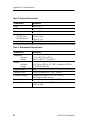
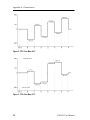
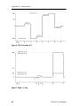
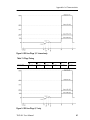
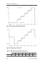
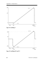
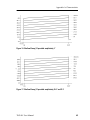
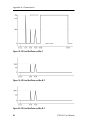
1
User Manual
TSG 601
Serial Digital Generator
070-8910-03
Copyright Tektronix, Inc., 1994. All rights reserved.
Printed in the U.S.A.
Tektronix products are covered by U.S. and foreign patents, issued
and pending. Information in this publication supersedes that in all
previously published material. Specification and price change privileges reserved.
For further information, contact: Tektronix, Inc., P.O. Box 1000,
Wilsonville OR 97070–1000, U.S.A. Phone: (503) 627–7111;
TLX: 192825; TWX: (910) 467–8708; Cable: TEKWSGT.
TEKTRONIX and TEK are registered trademarks of Tektronix, Inc.
Warranty
Tektronix warrants that this product will be free from defects in materials and workmanship for a period of one (1) year from the date of
shipment. If any such product proves defective during this warranty
period, Tektronix, at its option, either will repair the defective product without charge for parts and labor, or will provide a replacement
in exchange for the defective product.
In order to obtain service under this warranty, Customer must notify
Tektronix of the defect before the expiration of the warranty period
and make suitable arrangements for the performance of service. Customer shall be responsible for packaging and shipping the defective
product to the service center designated by Tektronix, with shipping
charges prepaid. Tektronix shall pay for the return of the product to
Customer if the shipment is to a location within the country in which
the Tektronix service center is located. Customer shall be responsible
for paying all shipping charges, duties, taxes, and any other charges
for products returned to any other locations.
This warranty shall not apply to any defect, failure or damage caused
by improper use or improper or inadequate maintenance and care.
Tektronix shall not be obligated to furnish service under this warranty a) to repair damage resulting from attempts by personnel other
than Tektronix representatives to install, repair or service the product; b) to repair damage resulting from improper use or connection to
incompatible equipment; c) to repair any damage or malfunction
caused by the use of non-Tektronix supplies; or d) to service a product that has been modified or integrated with other products when
the effect of such modification or integration increases the time or
difficulty of servicing the product.
This warranty is given by Tektronix with respect to this product
in lieu of any other warranties, expressed or implied. Tektronix
and its vendors disclaim any implied warranties of merchantability or fitness for a particular purpose. Tektronix’ responsibility to
repair or replace defective products is the sole and exclusive remedy provided to the customer for breach of this warranty. Tektronix and its vendors will not be liable for any indirect, special,
incidental, or consequential damages irrespective of whether
Tektronix or the vendor has advance notice of the possibility of
such damages.
EC Declaration of Conformity
We
Tektronix Holland N.V.
Marktweg 73A
8444 AB Heerenveen
The Netherlands
declare under sole responsibility that the
TSG 601 Handheld Serial Component Generator
meets the intent of Directive 89/336/EEC for Electromagnetic
Compatibility. Compliance was demonstrated to the following
specifications as listed in the Official Journal of the European
Communities:
EN 55011
Class A Radiated and Conducted Emissions
EN 50081-1 Emissions:
EN 60555-2 AC Power Line Harmonic Emissions
EN 50082-1 Immunity:
IEC 801-2 Electrostatic Discharge Immunity
IEC 801-3 RF Electromagnetic Field Immunity
IEC 801-4 Electrical Fast Transient/Burst Immunity
High-quality shielded cables must be used to ensure compliance to the
above listed standards.
Table of Contents
Getting Started . . . . . . . . . . . . . . . . . . . . . . . . . . . . . . . . . . . . .
1
Operating Basics . . . . . . . . . . . . . . . . . . . . . . . . . . . . . . . . . . .
Powering the Instrument . . . . . . . . . . . . . . . . . . . . . . . . . . . . . .
Keypad and Display Conventions . . . . . . . . . . . . . . . . . . . . . . .
Using your TSG 601 . . . . . . . . . . . . . . . . . . . . . . . . . . . . . . . . .
Outputting Serial Video Test Signals . . . . . . . . . . . . . . . . . .
Adjusting the Output Amplitude . . . . . . . . . . . . . . . . . . . . . .
Controlling the Video Component (Y, Cr, Cb) Channels . . .
Specifying 8- or 10-bit Data Words . . . . . . . . . . . . . . . . . . .
Specifying CRC Content of the Signal . . . . . . . . . . . . . . . . .
Inserting ID Messages . . . . . . . . . . . . . . . . . . . . . . . . . . . . . .
Editing ID Messages . . . . . . . . . . . . . . . . . . . . . . . . . . . . . . .
Positioning ID Messages . . . . . . . . . . . . . . . . . . . . . . . . . . . .
Setting up an ID Cycle . . . . . . . . . . . . . . . . . . . . . . . . . . . . .
Inserting Embedded Audio . . . . . . . . . . . . . . . . . . . . . . . . . .
Specifying Inserted Audio Channels in the Group . . . . . . . .
Specifying Audio Channel Frequencies . . . . . . . . . . . . . . . .
Changing Audio Channel Amplitudes . . . . . . . . . . . . . . . . .
Audio Channel ID . . . . . . . . . . . . . . . . . . . . . . . . . . . . . . . . .
Cable Simulation . . . . . . . . . . . . . . . . . . . . . . . . . . . . . . . . . .
Detecting Incorrect Termination . . . . . . . . . . . . . . . . . . . . . .
Saving (Storing) Presets and IDs . . . . . . . . . . . . . . . . . . . . .
Recalling Presets and IDs . . . . . . . . . . . . . . . . . . . . . . . . . . .
Details . . . . . . . . . . . . . . . . . . . . . . . . . . . . . . . . . . . . . . . . . . . .
CRCs . . . . . . . . . . . . . . . . . . . . . . . . . . . . . . . . . . . . . . . . . . .
ID Messages . . . . . . . . . . . . . . . . . . . . . . . . . . . . . . . . . . . . .
Embedded Audio . . . . . . . . . . . . . . . . . . . . . . . . . . . . . . . . . .
The SDI Checkfield Signals . . . . . . . . . . . . . . . . . . . . . . . . .
3
3
5
5
6
8
8
9
9
10
10
11
11
12
13
13
14
15
15
15
16
16
17
17
19
19
20
Appendix A: Characteristics . . . . . . . . . . . . . . . . . . . . . . . . .
Safety Standard Compliance . . . . . . . . . . . . . . . . . . . . . . . . . . .
Specification Tables . . . . . . . . . . . . . . . . . . . . . . . . . . . . . . . . . .
Waveform Diagrams . . . . . . . . . . . . . . . . . . . . . . . . . . . . . . . . .
25
25
26
37
Appendix B: Replaceable Parts . . . . . . . . . . . . . . . . . . . . . . .
53
TSG 601 User Manual
i
Contents
Appendix C: User Service . . . . . . . . . . . . . . . . . . . . . . . . . . . .
Battery Hints . . . . . . . . . . . . . . . . . . . . . . . . . . . . . . . . . . . . . . .
The BATTERY LOW Message . . . . . . . . . . . . . . . . . . . . . . .
Low-battery Shut Down . . . . . . . . . . . . . . . . . . . . . . . . . . . .
The Diagnostic Menu . . . . . . . . . . . . . . . . . . . . . . . . . . . . . . . .
Preventive Maintenance . . . . . . . . . . . . . . . . . . . . . . . . . . . . . . .
55
55
55
55
56
58
List of Figures
ii
Figure 1: 75% Color Bars, Y . . . . . . . . . . . . . . . . . . . . . . . . .
37
Figure 2: 75% Color Bars, B–Y . . . . . . . . . . . . . . . . . . . . . . .
38
Figure 3: 75% Color Bars, R–Y . . . . . . . . . . . . . . . . . . . . . . .
38
Figure 4: 100% Color Bars, Y . . . . . . . . . . . . . . . . . . . . . . . .
39
Figure 5: 100% Color Bars, B–Y . . . . . . . . . . . . . . . . . . . . . .
39
Figure 6: 100% Color Bars, R–Y . . . . . . . . . . . . . . . . . . . . . .
40
Figure 7: Pluge 1, Y only . . . . . . . . . . . . . . . . . . . . . . . . . . . . .
40
Figure 8: 625 Line Pluge 2, Y channel only . . . . . . . . . . . . . .
41
Figure 9: 525 Line Pluge 2, Y only . . . . . . . . . . . . . . . . . . . . .
41
Figure 10: 5-Step Staircase and Modulated 5-Step, Y . . . . .
42
Figure 11: 5-Step Staircase, B–Y and R–Y . . . . . . . . . . . . . .
42
Figure 12: 625 Line Modulated 5-Step, B–Y and R–Y . . . . .
43
Figure 13: 525 Line Modulated 5-Step, B–Y and R–Y . . . . .
43
Figure 14: Limit Ramp, Y . . . . . . . . . . . . . . . . . . . . . . . . . . . .
44
Figure 15: Limit Ramp, B–Y and R–Y . . . . . . . . . . . . . . . . .
44
Figure 16: Shallow Ramp, Y . . . . . . . . . . . . . . . . . . . . . . . . . .
45
Figure 17: Shallow Ramp, B–Y and R–Y . . . . . . . . . . . . . . .
45
Figure 18: 625 Line Mod Pulse and Bar, Y . . . . . . . . . . . . . .
46
Figure 19: 625 Line Mod Pulse and Bar, B–Y . . . . . . . . . . . .
46
Figure 20: 625 Line Mod Pulse and Bar, R–Y . . . . . . . . . . .
46
Figure 21: 525 Line Mod Pulse and Bar, Y . . . . . . . . . . . . . .
47
Figure 22: 525 Line Mod Pulse and Bar, B–Y . . . . . . . . . . . .
47
TSG 601 User Manual
Contents
Figure 23: 525 Line Mod Pulse and Bar, R–Y . . . . . . . . . . .
47
Figure 24: 60% Line Sweep with Markers, Y . . . . . . . . . . . .
48
Figure 25: 60% Line Sweep with Markers, B–Y and R–Y .
48
Figure 26: 500 kHz Bowtie, Y . . . . . . . . . . . . . . . . . . . . . . . . .
49
Figure 27: 500 kHz Bowtie, B–Y and R–Y . . . . . . . . . . . . . .
49
Figure 28: Bowtie Markers, Y channel only . . . . . . . . . . . . .
49
Figure 29: Convergence, Vertical Lines; Y channel only . . .
50
Figure 30: Convergence, Horizontal Lines; Y only . . . . . . .
50
Figure 31: Active Picture Markers, vertical limits . . . . . . . .
51
Figure 32: Active Picture Markers, horizontal limits . . . . . .
51
Figure 33: The Significance of the Active Picture Markers .
52
List of Tables
Table 1: Test Signal Characteristics . . . . . . . . . . . . . . . . . . .
26
Table 2: Encoding Parameters . . . . . . . . . . . . . . . . . . . . . . . .
28
Table 3: Serial Digital Video Output . . . . . . . . . . . . . . . . . . .
29
Table 4: Cable Simulator . . . . . . . . . . . . . . . . . . . . . . . . . . . .
30
Table 5: Character Identification . . . . . . . . . . . . . . . . . . . . .
31
Table 6: Signal Characteristics for Embedded Serial Audio
31
Table 7: Audio Channel Status Bits . . . . . . . . . . . . . . . . . . . .
32
Table 8: 525/59.94 Embedded Serial Audio Sample Dist. . .
33
Table 9: 625/50 Embedded Serial Audio Sample Dist. . . . . .
34
Table 10: Physical Characteristics . . . . . . . . . . . . . . . . . . . .
36
Table 11: Environmental Characteristics . . . . . . . . . . . . . . .
36
Table 12: 75% and 100% Color Bars Timing . . . . . . . . . . . .
37
Table 13: Pluge Timing . . . . . . . . . . . . . . . . . . . . . . . . . . . . . .
41
Table 14: 5-Step Staircase and Modulated 5-Step Timing . .
42
Table 15: Active Picture Markers Timing . . . . . . . . . . . . . . .
51
TSG 601 User Manual
iii
Contents
iv
TSG 601 User Manual
General Safety Summary
Review the following safety precautions to avoid injury and prevent
damage to this product or any products connected to it. To avoid
potential hazards, use this product only as specified.
Only qualified personnel should perform service procedures.
To Avoid Fire or Personal Injury
Observe All Terminal Ratings. To avoid fire or shock hazard, observe
all ratings and markings on the product. Consult the product manual
for further ratings information before making connections to the
product.
The common terminal is at ground potential. Do not connect the
common terminal to elevated voltages.
Replace Batteries Properly. Replace batteries only with the proper
type and rating specified.
Recharge Batteries Properly. Recharge batteries for the recommended
charge cycle only.
Use Proper AC Adapter. Use only the AC adapter specified for this
product.
Do Not Operate Without Covers. Do not operate this product with
covers or panels removed.
Use Proper Fuse. Use only the fuse type and rating specified for this
product.
Do Not Operate With Suspected Failures. If you suspect there is
damage to this product, have it inspected by qualified service
personnel.
Do Not Operate in Wet/Damp Conditions.
Do Not Operate in an Explosive Atmosphere.
TSG 601 User Manual
v
General Safety Summary
Safety Terms and Symbols
Terms in This Manual. These terms may appear in this manual:
WARNING. Warning statements identify conditions or practices that
could result in injury or loss of life.
CAUTION. Caution statements identify conditions or practices that
could result in damage to this product or other property.
Terms on the Product. These terms may appear on the product:
DANGER indicates an injury hazard immediately accessible as you
read the marking.
WARNING indicates an injury hazard not immediately accessible as
you read the marking.
CAUTION indicates a hazard to property including the product.
Symbols on the Product. These symbols may appear on the product:
CAUTION
Refer to Manual
Double
Insulated
Battery Recycling
This product contains a Nickel Cadmium (NiCd) battery, which must
be recycled or disposed of properly. For the location of a local
battery recycler in the U.S. or Canada, please contact:
RBRC
Rechargeable Battery Recycling Corp.
P.O. Box 141870
Gainesville, Florida 32614
vi
(800) BATTERY
(800) 227-7379
www.rbrc.com
TSG 601 User Manual
Getting Started
Please note the following statements before using your TSG 601.
CAUTION. Attempting to operate the TSG 601 with an improper AC
adapter can result in damage to the instrument. To avoid damage,
USE ONLY AN APPROPRIATE DC POWER SOURCE: Voltage must
be 9 to 15 VDC; the connector must have the NEGATIVE contact in
the center; and open-circuit voltage of the power source must not
exceed 18 VDC.
For best results, use the AC adapter that is supplied with the instrument. If the supplied adapter is incorrect for the local AC power supply, contact your nearest Tektronix representative.
WARNING. Install or replace batteries only with the instrument
switched OFF and the AC adapter disconnected.
Replace the batteries only with standard AA batteries (1.2–1.5 V,
nominal), or with the optional rechargeable battery pack.
If you use NiCad AA batteries or the optional battery pack, be sure to
set the battery type to “rechargeable” through the diagnostic menu
(see page 56). Failure to do so can result in damage to the batteries.
NOTE. Do not disconnect the AC adapter when the TSG 601 is
switched on. Some user settings may be lost, perhaps causing unexpected results the next time the instrument is switched on.
If you have any questions regarding the operation of this instrument,
please contact your nearest Tektronix representative or field office.
In the United States and Canada, you may also call the Tektronix
information number, 1-800-TEK-WIDE (1-800-835-9433), between
8:00 am and 5:00 pm Pacific time.
TSG 601 User Manual
1
2
TSG 601 User Manual
Operating Basics
Thank you for choosing the Tektronix TSG 601—and thank you for
reading this manual. To begin using the instrument as quickly as possible, see “Using your TSG 601,” beginning on page 5. For even
more information on selected topics, turn to “Details,” on page 17.
First, though, read the next section for tips on supplying power to the
instrument.
Powering the Instrument
The TSG 601 is DC powered. You may power it with the standard
AC adapter, the optional 9.6 V NiCad battery pack, eight standard
AA batteries, or a “BP” type battery pack with the correct voltage
and polarity. The external DC power connector is on the left side of
the instrument (see the illustration above). Open the battery compartTSG 601 User Manual
3
Operating Basics
ment by sliding the compartment door in the direction of the inscribed arrow until the door tabs line up with the slots in the case,
then remove the door. When selecting a power source for your
TSG 601, please remember:
H Attempting to use an improper AC adapter can cause permanent
damage to the instrument. USE AN APPROPRIATE DC POWER
SOURCE ONLY: Voltage must be between 9 and 15 VDC; the
center contact of the connector must be NEGATIVE polarity; and
open-circuit voltage must not exceed 18 VDC. For best results,
use the adapter supplied with the instrument.
H There is no need to remove the optional NiCad battery pack for
recharging. The TSG 601 will “trickle charge” the battery pack
whenever the standard AC adapter is used. It can take up to 16
hours to fully charge the battery pack. Note that charging will
occur only if the adapter supplies at least 12 V; make sure that the
adapter you use is appropriate for the local AC supply.
H AA batteries are not included with the instrument; buy them
locally. Rechargeable AA batteries may be used, but they are
NOT recharged automatically. To recharge AA batteries, remove
them from the instrument and use an appropriate battery charger.
For safety, read and follow the battery charger instructions. Do
NOT attempt to recharge standard alkaline batteries.
H After a minute with no key press, the display back light will be
dimmed to conserve battery charge.
H To guard against battery discharge if you forget to turn the
TSG 601 off, enable Auto Power Down through the Diagnostic
menu (see page 56).
H The TSG 601 can sense low battery voltage. It will warn you
when the charge is sufficient for approximately ten more minutes
of operation. The instrument will shut itself down when the battery voltage becomes too low for reliable operation. See the Battery hints in Appendix C, beginning on page 55 of this manual.
The ON key toggles instrument power On and Off.
4
TSG 601 User Manual
Operating Basics
Keypad and Display Conventions
Please see the Instruction card (p/n 070-8909-00) supplied with your
TSG 601 for a “tour” of the keypad and an explanation of the display
symbols. For your convenience, the following panels are excerpted
from the card.
Using your TSG 601
Here’s a list of what you can do with your TSG 601. Simple instructions for each operation begin on the indicated page.
H Output serial video test signals (page 6).
TSG 601 User Manual
5
Operating Basics
G Specify the peak–to–peak amplitude of the serial output, from
600 to 1000 mV (page 8).
G Choose the video components (Y, Cr, Cb) to be included in the
serial output (page 8).
G Specify 8- or 10-bit video sample words (page 9).
H Embed CRC information (used for “Error Detection and
Handling,” or EDH) in the output to detect or simulate errors
originating in the serial data path (page 9).
H Add an ID message to the video signal, and place it where you
want in the picture (pages 10, 11).
H Store up to eight ID messages for later use (pages 10, 16).
H Create a sequence of (up to four) stored ID messages that will
cycle continuously in the output (page 11).
H Embed Audio information in the serial video data path (page 12)
H Simulate the effect on your system of 50 m (164 ft.) of coaxial
cable (page 15).
H Detect improper termination of the serial video signal path
(page 15).
H Save all the current instrument settings as a “Preset” for later
recall (page 16).
Outputting Serial Video Test Signals
1. Connect the Serial Video Output of the instrument to your
system. Use 75 Ω cable and be sure that the signal path is
terminated properly.
6
TSG 601 User Manual
Operating Basics
2. Power the TSG (page 3) and switch it on. By default, the instrument will begin with most settings that were in effect when it was
switched off. Two exceptions: all video component channels will
be ON (see page 8); and the output amplitude will be 800 mV.
3. Select the appropriate serial video standard (625/50 or 525/60)
through the Diagnostic menu (pages 56, 58).
4. Return to normal operation by pressing the Test Signals key.
5. Select the desired test signal one of three ways:
G Press the Test Signals key repeatedly until the name of the
signal you want appears on the display. The signal will be
output as soon as the name is visible. Or...
G Use the Y and B keys to scroll through the list of signals until
you get to the desired signal. Or...
G Press the appropriate letter key (A through P) to “Direct-Select” the signal. The available signals and their corresponding
keys are listed below.
ÁÁÁÁÁÁÁÁÁÁÁÁÁÁÁÁÁ
ÁÁÁÁÁÁÁÁÁÁÁÁÁÁÁÁÁ
ÁÁÁÁÁÁÁÁÁÁÁÁÁÁÁÁÁ
ÁÁÁÁÁÁÁÁÁÁÁÁÁÁÁÁÁ
ÁÁÁÁÁÁÁÁÁÁÁÁÁÁÁÁÁ
ÁÁÁÁÁÁÁÁÁÁÁÁÁÁÁÁÁ
ÁÁÁÁÁÁÁÁÁÁÁÁÁÁÁÁÁ
ÁÁÁÁÁÁÁÁÁÁÁÁÁÁÁÁÁ
Test Signal
Direct-Select Key
75% Color Bars
A
100% Color Bars
B
Pluge 1 (BBC 1)
C
Pluge 2 (BBC 2)
D
5-Step Staircase
E
Limit Ramp
F
Shallow Ramp
G
TSG 601 User Manual
7
Operating Basics
ÁÁÁÁÁÁÁÁÁÁÁÁÁÁÁÁÁ
ÁÁÁÁÁÁÁÁÁÁÁÁÁÁÁÁÁ
ÁÁÁÁÁÁÁÁÁÁÁÁÁÁÁÁÁ
ÁÁÁÁÁÁÁÁÁÁÁÁÁÁÁÁÁ
ÁÁÁÁÁÁÁÁÁÁÁÁÁÁÁÁÁ
ÁÁÁÁÁÁÁÁÁÁÁÁÁÁÁÁÁ
ÁÁÁÁÁÁÁÁÁÁÁÁÁÁÁÁÁ
ÁÁÁÁÁÁÁÁÁÁÁÁÁÁÁÁÁ
ÁÁÁÁÁÁÁÁÁÁÁÁÁÁÁÁÁ
ÁÁÁÁÁÁÁÁÁÁÁÁÁÁÁÁÁ
ÁÁÁÁÁÁÁÁÁÁÁÁÁÁÁÁÁ
Test Signal
Direct-Select Key
Modulated 5-Step
H
Modulated Pulse and Bar
I
60% Line Sweep with Markers
J
Bowtie
K
Convergence
L
Equalizer SDI Checkfield
M
PLL SDI Checkfield
N
Matrix SDI Checkfield
O
Active Picture Markers
P
Adjusting the Output Amplitude
1. Press the key marked “Output Ampl.”
2. Select the desired output level with the arrow keys. The Y / B
keys change the level to the next higher or lower 100 mV
increment; A / " keys change it in 20 mV increments. Holding
an arrow key down will continually increase or decrease the level
until it reaches its minimum or maximum.
3. Press any rectangular key to exit the Output Amplitude Adjust
function.
Controlling the Video Component (Y, Cr, Cb) Channels
1. Enter the Output menu (press Shift, then Output Ampl.) and press
ENTER to reach “Channel Output Selection.” The display will
look something like this:
2. Use the A and " keys to position the flashing underline cursor to
the status (ON or OFF) of the channel you wish to change.
8
TSG 601 User Manual
Operating Basics
3. Toggle the status with the Y or B key. The channel status will
change instantly—you don’t have to press ENTER.
NOTE. All three component channels default to ON whenever the
TSG 601 is switched off and back on, regardless of prior “Channel
Output” settings.
Specifying 8- or 10-bit Data Words
1. If necessary, enter the Output menu (press Shift, then Output Ampl.).
2. Scroll down to the “Video Data Word Length” item with the
down arrow key and press ENTER to reach the word length
selection display.
3. Use the A or " key to toggle between 8 and 10 bits; press ENTER
to confirm the selection.
4. Press any rectangular key to exit the Output menu.
Specifying CRC Content of the Signal
1. Enter the CRC menu (press Shift, then CRC On/Off). The display
will resemble the following illustration.
2. Use the A / " keys to select FFCRC (Full Field CRC) or APCRC
(Active Picture CRC). Notice that the up/down symbol on the
second display line will move to indicate the chosen type of
CRC.
3. Use the Y / B keys to select the type of CRC to be encoded into
the output. The choices for the two types of CRCs are:
G FFCRC — NORM or ERR (Error)
G APCRC — NORM, ZERO, or ERR (Error)
See “CRCs” on page 17 for an explanation of these options.
TSG 601 User Manual
9
Operating Basics
4. Once the desired CRC choices appear on the display, press ENTER
to accept/invoke the selections.
5. Press any rectangular key to exit the CRC menu.
6. Toggle the inclusion of CRC data or errors on and off by pressing
the “CRC On/Off” key. The CRC status will be reported on the
second line of the display, alternating with the ID status.
Inserting ID Messages
H Toggle the ID message or cycle on and off with the “ID On/Off”
key.
Editing ID Messages
Please read “ID Messages” on page 19 before you first attempt to
edit a TSG 601 ID.
1. Enter the ID menu (press Shift, then ID On/Off).
2. Press the B key once to reach the “Edit ID #X” menu item. Note
that the ID# first shown on the display always indicates the
current (most recently recalled) ID.
3. Use the horizontal arrow keys to display the number of the ID
you want to edit, then press ENTER.
4. Use the arrow keys to move the character cursor. Specify the
character with the letter keys; press Shift to select symbols and
numbers. The “Sp” key will enter a space, blacking out the
underlying test pattern. The test pattern will show through a
“Blank” (Shift-SP).
5. When you have made all the desired changes, press ENTER to save
them. (Note: pressing any rectangular key will abort the edit and
exit the ID menu.) If the ID message you started with in step 3
was “on-screen” when you began the edit, the new message will
take its place. If not, and you wish to insert the new message,
press the Y key to reach the “Recall ID #X” menu item, select the
ID number with the horizontal arrow keys, and press ENTER.
6. As usual, press any rectangular key to exit the ID menu.
10
TSG 601 User Manual
Operating Basics
Positioning ID Messages
NOTE. Only the position of the currently displayed ID may be
changed. If you wish to change the picture location of a message that
is not displayed, you must first recall it through the ID menu or the
Recall menu.
1. Enter the ID menu (press Shift, then ID On/Off), if necessary.
2. With the Y and B keys, scroll to the “Position ID” menu item.
3. Press ENTER.
4. Use the arrow keys to move the message horizontally (H) and
vertically (V) in the picture.
5. When the ID occupies the desired position, press ENTER to save
the new location in memory and return to the ID menu. If you
press any rectangular key instead of ENTER, the ID will remain in
its new position—but will revert to the original location the next
time it is recalled from memory.
6. As usual, press any rectangular key to exit the ID menu.
Setting up an ID Cycle
1. Edit and save the ID messages that you want to cycle (see
“Editing ID messages,” page 10). Note the numbers of the IDs,
and the order in which they should appear.
2. Scroll through the ID menu to reach the “ID Cycle Setup” item,
then press ENTER. The display will resemble the following
illustration.
3. Use the A / " keys to move the underline cursor to one of the
four sequence “time intervals.” The IDs will appear in the order
that their numbers appear (from left to right) on the display.
TSG 601 User Manual
11
Operating Basics
4. Use the Y / B keys to select the number of the ID to appear
during each interval. Choose the hyphen (it’s below #1) to
eliminate the interval. If you want a blank interval (that is, a time
gap between ID messages), you must create an all-blank ID to put
in that interval.
5. When the correct information is in all four time interval positions, press ENTER to confirm the cycle setup. (Press any rectangular key to abort the cycle edit.)
6. To set the duration of each cycle time interval, press the Y key to
reach the “ID Cycle time” menu item. Use the horizontal arrow
keys to select the duration between one and nine seconds. Press
ENTER to confirm.
7. To replace the current ID with the ID cycle, scroll through the ID
menu to the “ID Cycle OFF” selection. Press a horizontal arrow
key to change the selection to “ID Cycle ON,” then press ENTER.
The cycle will appear in the picture if toggled on with the “ID
On/Off” key.
Inserting Embedded Audio
H Press the “Audio On/Off” key to alternately enable and disable
embedded audio in the serial data stream.
Though the TSG601 will provide 16 channels of audio, it can only
output a maximum of 4 channels at a time. Therefore the 16 channels have been broken up into 4 Groups of 4 channels each. Please
read “Embedded Audio” on page 19.
1. Enter the Audio menu (press Shift, then Audio On/Off). The display
will look something like this:
2. Go into the Audio Group Selection menu by pressing the ENTER
key. The display will change to:
12
TSG 601 User Manual
Operating Basics
3. Use the A and " keys to select the desired group of audio
channels (1–4, 5–8, 9–12, or 13–16). Press ENTER to confirm the
selection.
4. Press any rectangular key to exit the Audio menu, or use the Y /
B keys to go to the next selection within the Audio menu.
Specifying Inserted Audio Channels in the Group
When embedded audio is enabled, there must be at least two channels selected. This menu item allows you to select channels 1 and 2,
channels 3 and 4, or channels 1, 2, 3, and 4.
1. If necessary, enter the Audio menu (press Shift, then Audio On/Off).
2. Use the down key to scroll to the “Audio Channel Selection”
item, and press the ENTER key. The display will look something
like this:
3. Use the A and " keys to select the audio channel set. Press the
ENTER key to confirm the selection.
4. Press any rectangular key to exit the Audio menu, or use the Y /
B keys to go to the next selection within the Audio menu.
Specifying Audio Channel Frequencies
The TSG601 allows the selection of one of 26 different frequencies
plus mute for each individual channel within the group. The frequency of each channel within the group will be the same in all the
groups. To change the frequency assignments, do the following:
1. If necessary, enter the Audio menu (press Shift, then Audio On/Off).
TSG 601 User Manual
13
Operating Basics
2. Scroll down to the “Audio Frequency Selection” item and press
the ENTER key. The display will resemble this:
3. Use the A and " keys to select the desired audio channel, and use
the Y and B keys to select the frequency for that channel. Press
the ENTER key to confirm these choices. If a change was made,
the display will momentarily show the channel numbers that have
new frequency assignments.
4. Press any rectangular key to exit the Audio menu, or use the Y /
B keys to go to the next selection within the Audio menu.
Changing Audio Channel Amplitudes
Each audio channels output amplitude may be set from 0 dBFS to
–20 dBFS, in 1.0 dB increments. The following steps show how to
do this.
1. If necessary, enter the Audio menu (press Shift, then Audio On/Off ).
2. Scroll down to the “Audio Amplitude Selection” item and press
the ENTER key. The display will look something like this:
3. Use the A and " keys to select the desired audio channel, and use
the Y and B keys to select the amplitude for that channel. Press
the ENTER key to confirm these choices.
4. Press any rectangular key to exit the Audio menu, or use the Y /
B keys to go to the next selection within the Audio menu.
14
TSG 601 User Manual
Operating Basics
Audio Channel ID
Source ID in the audio channel status bits may be enabled or disabled through this menu item. Channel ID’s are preset to ch1 (channel 1), ch2 (channel 2), ch3 (channel 3), and ch4 (channel 4).
1. If necessary, enter the Audio menu (press Shift, then Audio On/Off ).
2. Scroll down to the “Audio Amplitude Selection” item and press
the ENTER key. The display will be similar to:
3. Use the A and " keys to toggle the ID between the enabled and
disabled states. Press the ENTER key to select the displayed state.
If the state was changed, the display will show each of the four
channels momentarily, while the SRAM is updated.
4. Press any rectangular key to exit the Audio menu, or use the Y /
B keys to go to the next selection within the Audio menu.
Cable Simulation
H To simulate the addition of 50 meters of 75 Ω coaxial cable
anywhere in your system, connect the TSG 601 into the signal
path with the two BNCs marked “APPROX 50M CABLE.” The
connectors are interchangeable, and the circuit will accurately
simulate 50 m of Belden 8281 cable—which attenuates the signal
by approximately 5.4 dB at 135 MHz—whether the TSG 601 is
switched on or off.
Detecting Incorrect Termination
H A special
symbol will “flash” in the upper right corner of the
TSG 601 display to indicate improper termination of the serial
video signal path. The symbol is displayed whenever the instrument detects return loss below approximately 10 dB, which
approximates termination impedance of less than 37.5 or greater than 150 TSG 601 User Manual
15
Operating Basics
Saving (Storing) Presets and IDs
1. Press Shift and then Recall. Note that the ID# first shown on the
display always indicates the current (most recently recalled) ID.
2. Scroll through the “STORE ID” (#1 through #8) and “STO
PRESET” (#1 through #4) locations with the left/right arrow
keys. The first line of any ID message already stored in the #
location will be shown in the bottom line of the display; use the
B key to see the second message line. Remember that storing the
current settings or ID will overwrite the contents of the Preset or
ID # location.
3. When the desired storage number is displayed, press ENTER to
save the current ID or Instrument settings. If you have stored an
ID, it will replace the old # contents on the bottom display line.
4. Press any rectangular key to exit the Store function.
Note that IDs are normally saved—when they are edited—through
the ID menu (see “Editing ID messages,” page 10). You may use the
Recall/Store button, however, if you wish to copy the current ID to
another memory location. Remember that the “current” ID is the last
message recalled through the ID menu or Recall; the ID will be copied (and the previous contents of the ID# location overwritten) even
when no message appears in the TSG 601 output (ID=Off).
A preset includes all of the instrument settings in effect when the
preset is saved, including the current output format, test signal, ID#,
and cycle setup. Note that ID messages themselves are not stored.
Thus, if a Preset “remembers” to display ID#4 (for example), the
latest message in ID#4 will appear whenever that Preset is recalled.
Remember, editing an ID message can have an affect on what you
get when you recall a preset.
Recalling Presets and IDs
1. Press the Recall key. Note that the ID# first shown on the display
always indicates the current (most recently recalled) ID.
2. Scroll through the “RECALL ID” (#1 through #8) and “RCL
PRESET” (#1 through #4) locations with the A / " keys. The
first line of an ID message will occupy the bottom line of the
display; use the B key to see the second line. For example, the
16
TSG 601 User Manual
Operating Basics
“factory” ID#1 is “Tektronix TSG601 Serial Digital.” The display
will first look like this:
Pressing the B key will change it to this:
You may find this feature useful if you save two or more IDs with
the same first line of text.
3. When the desired storage number is displayed, press ENTER to
recall the ID or Preset.
4. Press any rectangular key to exit the Recall menu.
Details
CRCs
CRCs (Cyclic Redundancy Codes) are used in serial digital video
systems as a means of error detection and handling (EDH). This section attempts to explain CRCs and their use, and freely paraphrases
the proposed SMPTE recommended practice on the topic, RP 165.
Those familiar with the concepts should skip down to “TSG 601
CRC Options,” below, for a discussion of the available CRCs.
Checkwords. CRCs are binary numbers that are computed from the
digital samples in the serial digital video frame. The CRCs serve a
similar function as the Parity Bit in the familiar RS-232 serial interface, but with much more sophistication. The transmitting device
calculates the CRC from the information it is sending, encodes it into
a checkword, and inserts the value into the transmitted data stream.
The receiving device calculates the CRC from the received information, decodes the received checkword, and compares the two numTSG 601 User Manual
17
Operating Basics
bers. If they are the same, we can be very confident that the picture
data has been transmitted correctly. Unequal numbers mean that
something has gone wrong in the process, and that the received data
is not identical to the data that was sent. Many receiving devices will
report the discrepancy as an error.
The TSG 601 is a transmitting device, and the companion SDA 601
is a receiving device. A digital VTR, of course, can be both.
Types of CRC. Two CRC checkwords are defined in SMPTE RP 165:
one derived from a full field of samples, and another based on samples from the active picture area only. The first is known as the Full
Field CRC (FFCRC) while the other is called the Active Picture CRC
(APCRC). The checkwords are transmitted in the “ancillary data”
area of the vertical interval portion of the digital video data stream.
Because some digital video equipment strips or ignores the vertical
interval, Tektronix engineers have devised another way of using the
Active Picture CRC that does not depend on a checkword embedded
in the serial data stream. It is called the Zero Active Picture CRC
(∅APCRC). For the ∅APCRC, the transmitting device computes the
APCRC as usual until the last five samples of the picture; then, the
transmitter produces five samples that will force the APCRC to equal
zero. If the receiving equipment also computes an APCRC of zero
from the received digital video, we can be as confident of error-free
transmission as with the standard APCRC—even when the vertical
interval portion is missing from the serial video data.
TSG 601 CRC options. The TSG 601 can generate:
Normal FFCRC
Erroneous FFCRC
Normal APCRC
Erroneous APCRC
∅APCRC
The Normal CRCs are calculated and encoded in accordance with
the (proposed) SMPTE recommended practice RP 165. The erroneous (or “forced error”) CRCs are created by beginning and ending
the computation one sample later than specified in RP 165. The erroneous CRCs, therefore, will always differ from the correct value.
18
TSG 601 User Manual
Operating Basics
ID Messages
The TSG 601 lets the user edit ID messages “off line.” This means
that you can edit a message without affecting the instrument’s output—or the ID currently inserted in the picture. To help prevent inadvertent changes to the current ID, the instrument will only insert ID
messages that have been saved through the ID menu or the Store key.
In the TSG 601, there are eight numbered storage locations for ID
messages, ID#1 through ID#8. Each location contains a simple “factory” message when the instrument is new (or immediately after a
“FACTORY RESET”—see page 57).
The procedure for creating and displaying a new message is:
1. Select an existing ID# for editing;
2. Change the message as desired (see page 10);
3. Save the changes (by pressing ENTER); and
4. Later recall that ID# through the ID menu or the Recall key.
If you edit the current ID# (that is, the one in the TSG output when
you begin the edit), the on-screen message will change in step 3. If
you edit a different ID#, the message will not change in step 3; rather, you’ll have to perform step 4 to insert the new message. If you
edit an ID# that is part of a currently active ID cycle, the new message will take the place of the old one the first time the ID# appears
after step 3.
To minimize the chance of outputting a test signal with an incorrect
ID message, please familiarize yourself with ID selection and editing
before you use the TSG 601 in a critical application.
Embedded Audio
The TSG 601 embedded audio function provides 16 channels of audio. The maximum output, however, is four channels at a time, so the
channels are divided into four groups of four channels:
Group 1
Group 2
Group 3
Group 4
TSG 601 User Manual
Channels 1 – 4
Channels 5 – 8
Channels 9 – 12
Channels 13 – 16
19
Operating Basics
Within the audio menus, the channels are called channels 1, 2, 3, and
4 of the group that you are working in. As there must be at least two
channels (AES/EBU pairs) selected when embedded audio is enabled, you may select channels 1 and 2, channels 3 and 4 or channels
1, 2, 3, and 4.
Separate frequencies and amplitudes may be assigned to each of the
four channels. The frequency and amplitude assigned to a channel
will be the same for that channel in all four groups. The frequency
may be set to any of 26 provided frequencies, or mute. The amplitude for each channel may be set in 1 dB increments from 0 dBFS to
–20 dBFS.
The embedded audio function also provides a source ID for each
channel. This ID is enabled or disabled for the whole group of four
channels at a time. When enabled, the source ID applies ch1, ch2,
ch3, and ch4 to the appropriate channels Status Bits, as shown in
Table 7. Audio sample distributions are shown in Tables 8 and 9.
The SDI Checkfield Signals
SDI (serial digital interface) Checkfield signals—also known as
Pathological signals—are designed to test the low frequency response of serial digital video equipment. The three SDI Checkfield
signals in the TSG 601 are defined in the (proposed) SMPTE Recommended Practice RP 178; they are the Cable Equalization (Equalizer), Phase Locked Loop (PLL), and Matrix Checkfields.
The Equalizer SDI Checkfield signal tests the automatic equalizer
circuits of receiving equipment. It has been arranged to create a serial data stream with the maximum possible dc content. In practice,
the digital data contains a repeating pattern of 19 high or low states
followed by one opposite state; thus, for the longest possible period
(several times each field), the signal will be essentially “dc,” with
opposite polarity states occurring only once in every twenty clock
intervals.
The PLL Checkfield Signal tests the equipment’s ability to lock to
the serial data stream. It has been configured to give the serial data
the maximum possible low frequency content and the fewest possible
zero crossings; that is, the longest possible time between high–low or
low–high transitions in the signal. In practice, the data contains—
several times each field—a repeating pattern of 20 high states fol20
TSG 601 User Manual
Operating Basics
lowed by 20 low states. This is the lowest frequency possible, given
the data encoding schemes that are specified in the serial digital video standards.
The third TSG 601 SDI Checkfield signal is a matrix of the other
two. For a much more complete discussion of SDI Check Fields and
their use, please see SMPTE RP 178 and Tektronix publication
25W-7203-1, “A Guide to Digital Television Systems and Measurements.”
TSG 601 User Manual
21
Operating Basics
22
TSG 601 User Manual
Appendices
Appendix A: Characteristics
The information in this section is included for the convenience of the
TSG 601 operator. It is not intended as a complete list of guaranteed
specifications. The waveform illustrations represent properly decoded output. For a full list of instrument specifications, as well as
performance verification and adjustment procedures, please see the
TSG 601 Service Manual (Tektronix p/n 070-8911-XX).
NOTE. Shielded cables were used in the EMI certification of this
instrument; therefore, it is recommended that shielded cables be used
when operating. (EC 92)
Safety Standard Compliance
The following safety standards apply to the TSG 601:
H ANSI S82 — Safety Standard for Electrical and Electronic Test,
Measuring, Controlling, and Related Equipment, 1988.
H CAN/CSA C22.2 No. 231 M89 — CSA Safety Requirements for
Electrical and Electronic Measuring and Test Equipment.
H IEC1010-1 — Safety Requirements for Electrical Equipment for
Measurement, Control, and Laboratory Use (1990).
H UL1244 — Standard for Electrical and Electronic Measuring and
Testing Equipment, Second Edition (1980).
TSG 601 User Manual
25
Appendix A: Characteristics
Specification Tables
ÁÁÁÁÁÁÁÁÁÁÁÁÁÁÁÁÁÁÁÁÁÁ
ÁÁÁÁÁÁÁÁÁÁÁÁÁÁÁÁÁÁÁÁÁÁ
ÁÁÁÁÁÁÁÁ
ÁÁÁÁÁÁÁÁÁÁÁÁÁÁÁ
ÁÁÁÁÁÁÁÁÁÁÁÁÁÁÁÁÁÁÁÁÁÁÁ
ÁÁÁÁÁÁÁÁÁÁÁÁÁÁÁÁÁÁÁÁÁÁÁ
ÁÁÁÁÁÁÁÁÁÁÁÁÁÁÁÁÁÁÁÁÁÁÁ
ÁÁÁÁÁÁÁÁÁÁÁÁÁÁÁÁÁÁÁÁÁÁÁ
ÁÁÁÁÁÁÁÁÁÁÁÁÁÁÁÁÁÁÁÁÁÁÁ
ÁÁÁÁÁÁÁÁÁÁÁÁÁÁÁÁÁÁÁÁÁÁÁ
ÁÁÁÁÁÁÁÁÁÁÁÁÁÁÁÁÁÁÁÁÁÁÁ
ÁÁÁÁÁÁÁÁÁÁÁÁÁÁÁÁÁÁÁÁÁÁÁ
ÁÁÁÁÁÁÁÁÁÁÁÁÁÁÁÁÁÁÁÁÁÁÁ
ÁÁÁÁÁÁÁÁÁÁÁÁÁÁÁÁÁÁÁÁÁÁÁ
ÁÁÁÁÁÁÁÁÁÁÁÁÁÁÁÁÁÁÁÁÁÁÁ
ÁÁÁÁÁÁÁÁÁÁÁÁÁÁÁÁÁÁÁÁÁÁÁ
ÁÁÁÁÁÁÁÁÁÁÁÁÁÁÁÁÁÁÁÁÁÁÁ
ÁÁÁÁÁÁÁÁÁÁÁÁÁÁÁÁÁÁÁÁÁÁÁ
ÁÁÁÁÁÁÁÁÁÁÁÁÁÁÁÁÁÁÁÁÁÁÁ
ÁÁÁÁÁÁÁÁÁÁÁÁÁÁÁÁÁÁÁÁÁÁÁ
ÁÁÁÁÁÁÁÁÁÁÁÁÁÁÁÁÁÁÁÁÁÁÁ
ÁÁÁÁÁÁÁÁÁÁÁÁÁÁÁÁÁÁÁÁÁÁÁ
ÁÁÁÁÁÁÁÁÁÁÁÁÁÁÁÁÁÁÁÁÁÁÁ
ÁÁÁÁÁÁÁÁÁÁÁÁÁÁÁÁÁÁÁÁÁÁÁ
ÁÁÁÁÁÁÁÁÁÁÁÁÁÁÁÁÁÁÁÁÁÁÁ
ÁÁÁÁÁÁÁÁÁÁÁÁÁÁÁÁÁÁÁÁÁÁÁ
ÁÁÁÁÁÁÁÁÁÁÁÁÁÁÁÁÁÁÁÁÁÁÁ
ÁÁÁÁÁÁÁÁÁÁÁÁÁÁÁÁÁÁÁÁÁÁÁ
ÁÁÁÁÁÁÁÁÁÁÁÁÁÁÁÁÁÁÁÁÁÁÁ
ÁÁÁÁÁÁÁÁÁÁÁÁÁÁÁÁÁÁÁÁÁÁÁ
ÁÁÁÁÁÁÁÁÁÁÁÁÁÁÁÁÁÁÁÁÁÁÁ
Table 1: Test Signal Characteristics
Characteristic
Information
75% Color Bars
See Figures 1, 2, and 3, and Table 12
100% Color Bars
See Figures 4, 5, and 6, and Table 12
Pluge (BBC 1)
Field Timing, 625/50
700 mV
105 mV
Field Timing, 525/60
700 mV
105 mV
See Figure 7 and Table 13
Pluge (BBC 2)
Field Timing, 625/50
700 mV
450 mV
200 mV
110 mV
Field Timing, 525/60
700 mV
450 mV
200 mV
110 mV
See Figures 8 and 9, and Table 13
5-Step Staircase
Amplitude
Y channel
B–Y, R–Y
See Figures 10 and 11, and Table 14
Mod 5-Step
Amplitude
Y channel
525 B–Y, R–Y
625 B–Y
625 R–Y
See Figures 10, 12. and 13
Limit Ramp
See Figures 14 and 15
In 8-bit, extends from word 01 to 254
In 10-bit, extends from word 04 to 1016
26
Lines 83–166
Lines 167–250
Lines 72–142
Lines 143–212
Lines 63–114
Lines 115–166
Lines 167–218
Lines 219–270
Lines 55–98
Lines 99–142
Lines 143–185
Lines 186–229
0 to 702.4 mV in 176-word steps
–351.6 to +351.6 mV in 180-word steps
0 to 702.4 mV in 176-word steps
–157.3 mV
83.7 mV
94.4 mV
TSG 601 User Manual
Appendix A: Characteristics
ÁÁÁÁÁÁÁÁÁÁÁÁÁÁÁÁÁÁÁÁÁÁÁ
ÁÁÁÁÁÁÁÁÁÁÁÁÁÁÁÁÁÁÁÁÁÁÁ
ÁÁÁÁÁÁÁÁÁÁÁÁÁÁÁÁÁÁÁÁÁÁÁ
ÁÁÁÁÁÁÁÁ
ÁÁÁÁÁÁÁÁÁÁÁÁÁÁÁÁ
ÁÁÁÁÁÁÁÁÁÁÁÁÁÁÁÁÁÁÁÁÁÁÁÁ
ÁÁÁÁÁÁÁÁÁÁÁÁÁÁÁÁÁÁÁÁÁÁÁÁ
ÁÁÁÁÁÁÁÁÁÁÁÁÁÁÁÁÁÁÁÁÁÁÁÁ
ÁÁÁÁÁÁÁÁÁÁÁÁÁÁÁÁÁÁÁÁÁÁÁÁ
ÁÁÁÁÁÁÁÁÁÁÁÁÁÁÁÁÁÁÁÁÁÁÁÁ
ÁÁÁÁÁÁÁÁÁÁÁÁÁÁÁÁÁÁÁÁÁÁÁÁ
ÁÁÁÁÁÁÁÁÁÁÁÁÁÁÁÁÁÁÁÁÁÁÁÁ
ÁÁÁÁÁÁÁÁÁÁÁÁÁÁÁÁÁÁÁÁÁÁÁÁ
ÁÁÁÁÁÁÁÁÁÁÁÁÁÁÁÁÁÁÁÁÁÁÁÁ
ÁÁÁÁÁÁÁÁÁÁÁÁÁÁÁÁÁÁÁÁÁÁÁÁ
ÁÁÁÁÁÁÁÁÁÁÁÁÁÁÁÁÁÁÁÁÁÁÁÁ
ÁÁÁÁÁÁÁÁÁÁÁÁÁÁÁÁÁÁÁÁÁÁÁÁ
ÁÁÁÁÁÁÁÁÁÁÁÁÁÁÁÁÁÁÁÁÁÁÁÁ
ÁÁÁÁÁÁÁÁÁÁÁÁÁÁÁÁÁÁÁÁÁÁÁÁ
ÁÁÁÁÁÁÁÁÁÁÁÁÁÁÁÁÁÁÁÁÁÁÁÁ
ÁÁÁÁÁÁÁÁÁÁÁÁÁÁÁÁÁÁÁÁÁÁÁÁ
ÁÁÁÁÁÁÁÁÁÁÁÁÁÁÁÁÁÁÁÁÁÁÁÁ
ÁÁÁÁÁÁÁÁÁÁÁÁÁÁÁÁÁÁÁÁÁÁÁÁ
ÁÁÁÁÁÁÁÁÁÁÁÁÁÁÁÁÁÁÁÁÁÁÁÁ
ÁÁÁÁÁÁÁÁÁÁÁÁÁÁÁÁÁÁÁÁÁÁÁÁ
ÁÁÁÁÁÁÁÁÁÁÁÁÁÁÁÁÁÁÁÁÁÁÁÁ
ÁÁÁÁÁÁÁÁÁÁÁÁÁÁÁÁÁÁÁÁÁÁÁÁ
ÁÁÁÁÁÁÁÁÁÁÁÁÁÁÁÁÁÁÁÁÁÁÁÁ
ÁÁÁÁÁÁÁÁÁÁÁÁÁÁÁÁÁÁÁÁÁÁÁÁ
ÁÁÁÁÁÁÁÁÁÁÁÁÁÁÁÁÁÁÁÁÁÁÁÁ
ÁÁÁÁÁÁÁÁÁÁÁÁÁÁÁÁÁÁÁÁÁÁÁÁ
ÁÁÁÁÁÁÁÁÁÁÁÁÁÁÁÁÁÁÁÁÁÁÁÁ
ÁÁÁÁÁÁÁÁÁÁÁÁÁÁÁÁÁÁÁÁÁÁÁÁ
ÁÁÁÁÁÁÁÁÁÁÁÁÁÁÁÁÁÁÁÁÁÁÁÁ
ÁÁÁÁÁÁÁÁÁÁÁÁÁÁÁÁÁÁÁÁÁÁÁÁ
Table 1: Test Signal Characteristics (Cont.)
Characteristic
Information
Shallow Ramp
Amplitude
Pedestal (variable)
Y channel
B–Y, R–Y
Risetimes
Y channel
B–Y, R–Y
See Figures 16 and 17
80 mV
Mod Pulse and Bar (625
lines/50 Hz)
4T Pulse HAD
10T Pulse HAD
Pulse Amplitude
Y
B–Y
R–Y
2T Pulse HAD
See Figures 18, 19, and 20
Mod Pulse and Bar (525
lines/60 Hz)
12.5T Pulse HAD
See Figures 21, 22, and 23
Pulse Amplitude
Y
B–Y
R–Y
2T Pulse HAD
0 to 700 mV
–350 to +350 mV
200 ns Nominal
280 ns Nominal
400 ns
1000 ns (1.0 µs)
350.0 mV
196.3 mV
248.1 mV
200 ns (Y channel only)
1562.5 ns
(in NTSC, encodes to 12.5T modulated pulse, ∅ = 60.7°)
350.0 mV
196.3 mV
248.1 mV
200 ns (Y channel only)
60% Line Sweep W/Markers
Amplitude
Frequency Range
Y channel
R–Y, B–Y
Marker Frequencies
Y channel
R–Y, B–Y
See Figures 24 and 25
420 mV
500 kHz Bowtie
Y channel
R–Y, B–Y
Amplitude
See Figures 26, 27, and 28
500 kHz sine wave
502 kHz sine wave
350 mV
TSG 601 User Manual
250 kHz–5.75 MHz
125 kHz–2.75 MHz
0.5, 1, 2, 3, 4, and 5 MHz
0.25, 0.5, 1, 1.5, 2, and 2.5 MHz
27
Appendix A: Characteristics
ÁÁÁÁÁÁÁÁÁÁÁÁÁÁÁÁÁÁÁÁÁÁ
ÁÁÁÁÁÁÁÁÁÁÁÁÁÁÁÁÁÁÁÁÁÁ
ÁÁÁÁÁÁÁÁÁÁÁÁÁÁÁÁÁÁÁÁÁÁ
ÁÁÁÁÁÁÁÁ
ÁÁÁÁÁÁÁÁÁÁÁÁÁÁÁ
ÁÁÁÁÁÁÁÁÁÁÁÁÁÁÁÁÁÁÁÁÁÁÁ
ÁÁÁÁÁÁÁÁÁÁÁÁÁÁÁÁÁÁÁÁÁÁÁ
ÁÁÁÁÁÁÁÁÁÁÁÁÁÁÁÁÁÁÁÁÁÁÁ
ÁÁÁÁÁÁÁÁÁÁÁÁÁÁÁÁÁÁÁÁÁÁÁ
ÁÁÁÁÁÁÁÁÁÁÁÁÁÁÁÁÁÁÁÁÁÁÁ
ÁÁÁÁÁÁÁÁÁÁÁÁÁÁÁÁÁÁÁÁÁÁÁ
ÁÁÁÁÁÁÁÁÁÁÁÁÁÁÁÁÁÁÁÁÁÁÁ
ÁÁÁÁÁÁÁÁÁÁÁÁÁÁÁÁÁÁÁÁÁÁÁ
ÁÁÁÁÁÁÁÁÁÁÁÁÁÁÁÁÁÁÁÁÁÁÁ
ÁÁÁÁÁÁÁÁÁÁÁÁÁÁÁÁÁÁÁÁÁÁÁ
ÁÁÁÁÁÁÁÁÁÁÁÁÁÁÁÁÁÁÁÁÁÁÁ
ÁÁÁÁÁÁÁÁÁÁÁÁÁÁÁÁÁÁÁÁÁÁÁ
ÁÁÁÁÁÁÁÁÁÁÁÁÁÁÁÁÁÁÁÁÁÁÁ
ÁÁÁÁÁÁÁÁÁÁÁÁÁÁÁÁÁÁÁÁÁÁÁ
ÁÁÁÁÁÁÁÁÁÁÁÁÁÁÁÁÁÁÁÁÁÁÁ
ÁÁÁÁÁÁÁÁÁÁÁÁÁÁÁÁÁÁÁÁÁÁÁ
ÁÁÁÁÁÁÁÁÁÁÁÁÁÁÁÁÁÁÁÁÁÁÁ
ÁÁÁÁÁÁÁÁÁÁÁÁÁÁÁÁÁÁÁÁÁÁ
ÁÁÁÁÁÁÁÁÁÁÁÁÁÁÁÁÁÁÁÁÁÁ
ÁÁÁÁÁÁÁÁÁÁÁÁÁÁÁÁÁÁÁÁÁÁ
ÁÁÁÁÁÁÁÁ
ÁÁÁÁÁÁÁÁÁÁÁÁÁÁÁ
ÁÁÁÁÁÁÁÁÁÁÁÁÁÁÁÁÁÁÁÁÁÁÁ
ÁÁÁÁÁÁÁÁÁÁÁÁÁÁÁÁÁÁÁÁÁÁÁ
ÁÁÁÁÁÁÁÁÁÁÁÁÁÁÁÁÁÁÁÁÁÁÁ
ÁÁÁÁÁÁÁÁÁÁÁÁÁÁÁÁÁÁÁÁÁÁÁ
ÁÁÁÁÁÁÁÁÁÁÁÁÁÁÁÁÁÁÁÁÁÁÁ
ÁÁÁÁÁÁÁÁÁÁÁÁÁÁÁÁÁÁÁÁÁÁÁ
ÁÁÁÁÁÁÁÁÁÁÁÁÁÁÁÁÁÁÁÁÁÁÁ
ÁÁÁÁÁÁÁÁÁÁÁÁÁÁÁÁÁÁÁÁÁÁÁ
Table 1: Test Signal Characteristics (Cont.)
Characteristic
Information
Convergence
Amplitude
Pattern
Pulse HAD
See Figures 29 and 30
525 mV (75%)
Crosshatch: 14 horiz./15 vert. lines
225 ± 25 ns
Equalizer SDI Checkfield
Per SMPTE RP 178
PLL SDI Checkfield
Per SMPTE RP 178
Matrix SDI Checkfield
Field Timing, 625/50
Equalizer
PLL
Field Timing, 525/60
Equalizer
PLL
Per SMPTE RP 178
Active Picture Markers
Field Timing, 625/50
Vertical limits
Horizontal limits
Field Timing, 525/60
Vertical limits
Horizontal limits
See Figures 31, 32, and 33, and Table 15
Lines 24 through 166
Lines 167 through 310
Lines 21 through 141
Lines 142 through 262
Lines 24 and 310
Lines 25 through 309
Lines 21 and 262
Lines 22 through 261
Table 2: Encoding Parameters
Characteristic
Information
Standards Conformance
CCIR rec 601
Coded Signals
Y, B–Y, and R–Y
Samples per complete line
Luminance (Y)
Color Difference
(B–Y, R–Y)
525/60; 625/50
858; 864
429; 432
Sampling Structure
Orthogonal, line, field, and picture repetitive. R–Y and B–Y
samples co-sited with odd (1st, 3rd, 5th, etc.) Y samples in
each line.
28
TSG 601 User Manual
Appendix A: Characteristics
ÁÁÁÁÁÁÁÁÁÁÁÁÁÁÁÁÁÁÁÁÁÁÁ
ÁÁÁÁÁÁÁÁÁÁÁÁÁÁÁÁÁÁÁÁÁÁÁ
ÁÁÁÁÁÁÁÁÁÁÁÁÁÁÁÁÁÁÁÁÁÁÁ
ÁÁÁÁÁÁÁÁ
ÁÁÁÁÁÁÁÁÁÁÁÁÁÁÁÁ
ÁÁÁÁÁÁÁÁÁÁÁÁÁÁÁÁÁÁÁÁÁÁÁÁ
ÁÁÁÁÁÁÁÁÁÁÁÁÁÁÁÁÁÁÁÁÁÁÁÁ
ÁÁÁÁÁÁÁÁÁÁÁÁÁÁÁÁÁÁÁÁÁÁÁÁ
ÁÁÁÁÁÁÁÁÁÁÁÁÁÁÁÁÁÁÁÁÁÁÁÁ
ÁÁÁÁÁÁÁÁÁÁÁÁÁÁÁÁÁÁÁÁÁÁÁÁ
ÁÁÁÁÁÁÁÁÁÁÁÁÁÁÁÁÁÁÁÁÁÁÁÁ
ÁÁÁÁÁÁÁÁÁÁÁÁÁÁÁÁÁÁÁÁÁÁÁÁ
ÁÁÁÁÁÁÁÁÁÁÁÁÁÁÁÁÁÁÁÁÁÁÁÁ
ÁÁÁÁÁÁÁÁÁÁÁÁÁÁÁÁÁÁÁÁÁÁÁÁ
ÁÁÁÁÁÁÁÁÁÁÁÁÁÁÁÁÁÁÁÁÁÁÁÁ
ÁÁÁÁÁÁÁÁÁÁÁÁÁÁÁÁÁÁÁÁÁÁÁÁ
ÁÁÁÁÁÁÁÁÁÁÁÁÁÁÁÁÁÁÁÁÁÁÁÁ
ÁÁÁÁÁÁÁÁÁÁÁÁÁÁÁÁÁÁÁÁÁÁÁÁ
ÁÁÁÁÁÁÁÁÁÁÁÁÁÁÁÁÁÁÁÁÁÁÁÁ
Table 2: Encoding Parameters (Cont.)
Characteristic
Information
Sampling Frequency
Luminance (Y)
B–Y and R–Y
13.5 MHz
6.75 MHz
Form of Coding
Samples/Digital Active Line
Luminance (Y)
B–Y and R–Y
Video Signal/Quantization
Level Correspondence
Luminance (Y)
B–Y and R–Y
Uniformly quantized PCM, 10 bits per sample, for the
luminance signal and each color difference signal.
720
360
(10 bit video; quantization levels 0 to 1023)
Spans 877 quantization levels, with black (0 mV) corresponding to level 64 and peak white (700 mV) corresponding to level 940.
Spans 897 quantization levels in the center of the quantization scale. Level 512 corresponds to 0 mV, level 64 to –350
mV, and level 960 to + 350 mV.
NOTE. Performance Requirements in the following tables are valid
only if the instrument has been adjusted at approximately 25° C, is
being operated within environmental limits (see Table 11), and has
had a minimum warm-up of 20 minutes.
ÁÁÁÁÁÁÁÁÁÁÁÁÁÁÁÁÁÁÁÁÁÁÁ
ÁÁÁÁÁÁÁÁÁÁÁÁÁÁÁÁÁÁÁÁÁÁÁ
ÁÁÁÁÁÁÁÁÁÁÁÁÁÁÁÁÁÁÁÁÁÁÁ
ÁÁÁÁÁÁÁÁ
ÁÁÁÁÁÁÁÁÁÁÁÁÁÁÁÁÁ
ÁÁÁÁÁÁÁÁÁÁÁÁÁÁÁÁÁÁÁÁÁÁÁÁÁ
ÁÁÁÁÁÁÁÁÁÁÁÁÁÁÁÁÁÁÁÁÁÁÁÁÁ
ÁÁÁÁÁÁÁÁÁÁÁÁÁÁÁÁÁÁÁÁÁÁÁÁÁ
ÁÁÁÁÁÁÁÁÁÁ
ÁÁÁÁÁÁÁÁÁÁÁÁÁÁÁÁÁÁÁÁÁÁÁÁÁ
ÁÁÁÁÁÁÁÁÁÁÁÁÁÁÁÁÁÁÁÁÁÁÁÁÁ
ÁÁÁÁÁÁÁÁÁÁÁÁÁÁÁÁÁÁÁÁÁÁÁÁÁ
ÁÁÁÁÁÁÁÁÁÁÁÁÁÁÁÁÁÁÁÁÁÁÁÁÁ
ÁÁÁÁÁÁÁÁÁÁÁÁÁÁÁÁÁÁÁÁÁÁÁÁÁ
Table 3: Serial Digital Video Output
Characteristic
Performance
Requirements
Supplemental Information
Connectors
3 BNCs, 75 Ω
Number of Outputs
1 component serial video.
Digital Format
CCIR 601 Component 525/625,
8 or 10 bits data, scrambled
NRZI; complies with CCIR 656
and SMPTE 259M.
Bit Rate
270 Mb/s
Source Impedance
75 Ω
TSG 601 User Manual
29
Appendix A: Characteristics
ÁÁÁÁÁÁÁÁÁÁÁÁÁÁÁÁÁÁÁÁÁÁ
ÁÁÁÁÁÁÁÁÁÁÁÁÁÁÁÁÁÁÁÁÁÁ
ÁÁÁÁÁÁÁÁÁÁÁÁÁÁÁÁÁÁÁÁÁÁ
ÁÁÁÁÁÁÁÁ
ÁÁÁÁÁÁÁÁÁÁÁÁÁÁÁÁ
ÁÁÁÁÁÁÁÁÁÁÁÁÁÁÁÁÁÁÁÁÁÁÁÁ
ÁÁÁÁÁÁÁÁÁÁÁÁÁÁÁÁÁÁÁÁÁÁÁÁ
ÁÁÁÁÁÁÁÁÁÁÁÁÁÁÁÁÁÁÁÁÁÁÁÁ
ÁÁÁÁÁÁÁÁÁÁÁÁÁÁÁÁÁÁÁÁÁÁÁÁ
ÁÁÁÁÁÁÁÁÁÁÁÁÁÁÁÁÁÁÁÁÁÁÁÁ
ÁÁÁÁÁÁÁÁÁÁÁÁÁÁÁÁÁÁÁÁÁÁÁÁ
ÁÁÁÁÁÁÁÁÁÁÁÁÁÁÁÁÁÁÁÁÁÁÁÁ
ÁÁÁÁÁÁÁÁÁÁÁÁÁÁÁÁÁÁÁÁÁÁÁÁ
ÁÁÁÁÁÁÁÁÁÁÁÁÁÁÁÁÁÁÁÁÁÁÁÁ
ÁÁÁÁÁÁÁÁÁÁÁÁÁÁÁÁÁÁÁÁÁÁÁÁ
ÁÁÁÁÁÁÁÁÁÁÁÁÁÁÁÁÁÁÁÁÁÁÁÁ
ÁÁÁÁÁÁÁÁÁÁÁÁÁÁÁÁÁÁÁÁÁÁÁÁ
ÁÁÁÁÁÁÁÁÁÁÁÁÁÁÁÁÁÁÁÁÁÁÁÁ
ÁÁÁÁÁÁÁÁÁÁÁÁÁÁÁÁÁÁÁÁÁÁÁÁ
ÁÁÁÁÁÁÁÁÁÁÁÁÁÁÁÁÁÁÁÁÁÁÁÁ
ÁÁÁÁÁÁÁÁÁÁÁÁÁÁÁÁÁÁÁÁÁÁÁÁ
ÁÁÁÁÁÁÁÁÁÁÁÁÁÁÁÁÁÁÁÁÁÁÁÁ
ÁÁÁÁÁÁÁÁÁÁÁÁÁÁÁÁÁÁÁÁÁÁÁÁ
ÁÁÁÁÁÁÁÁÁÁÁÁÁÁÁÁÁÁÁÁÁÁÁÁ
ÁÁÁÁÁÁÁÁÁÁÁÁÁÁÁÁÁÁÁÁÁÁÁÁ
ÁÁÁÁÁÁÁÁÁÁÁÁÁÁÁÁÁÁÁÁÁÁ
ÁÁÁÁÁÁÁÁÁÁÁÁÁÁÁÁÁÁÁÁÁÁ
ÁÁÁÁÁÁÁÁÁÁÁÁÁÁÁÁÁÁÁÁÁÁ
ÁÁÁÁÁÁÁÁ
ÁÁÁÁÁÁÁÁÁÁÁÁÁÁÁÁ
ÁÁÁÁÁÁÁÁÁÁÁÁÁÁÁÁÁÁÁÁÁÁÁÁ
ÁÁÁÁÁÁÁÁÁÁÁÁÁÁÁÁÁÁÁÁÁÁÁÁ
ÁÁÁÁÁÁÁÁÁÁÁÁÁÁÁÁÁÁÁÁÁÁÁÁ
ÁÁÁÁÁÁÁÁÁÁÁÁÁÁÁÁÁÁÁÁÁÁÁÁ
ÁÁÁÁÁÁÁÁ
ÁÁÁÁÁÁÁÁÁ
ÁÁÁÁÁÁÁÁ
ÁÁÁÁÁÁÁÁÁ
Table 3: Serial Digital Video Output (Cont.)
Characteristic
Performance
Requirements
Supplemental Information
Return Loss
≥ 15 dB, 5 MHz–270 MHz
Instrument switched on
Termination Detector
Triggers display symbol when
return loss of the signal path is
≤ 10 dB (approximates termination impedance of ≤ 37.5 Ω and
≥ 150 Ω).
Signal Amplitude
Variable from 600 mV to 1000
mV in the following steps:
Coarse — 100 mV increments
on even 100 mV levels
Fine — 20 mV increments
Absolute accuracy
at 800 mV setting
Relative accuracy
Coarse increments
Fine increments
800 ± 20 mV
100 ± 8 mV
20 ± 8 mV
From last 100 mV setting
DC Offset
0 ± 0.5 Volts
Rise and Fall Times
400–1000 ps
20% to 80% amplitude points
Jitter
less than ± 360 ps
over one line
Error Detection Ancillary
Data
Active picture CRC (0-AP-CRC,
Tek proprietary) on lines 9 & 272
(525) or 5 & 318 (625).
EDH (SMPTE RP-165)
Table 4: Cable Simulator
Characteristic
Performance
Requirements
–5.4 dB ± 0.5 dB at 135 MHz
(Approximates a 50 meter length
of Belden 8281 coax cable)
Length
Return Loss
30
Supplemental Information
≥ 20 dB from 5 MHz to
270 MHz
TSG 601 User Manual
Appendix A: Characteristics
ÁÁÁÁÁÁÁÁÁÁÁÁÁÁÁÁÁÁÁÁÁÁÁ
ÁÁÁÁÁÁÁÁÁÁÁÁÁÁÁÁÁÁÁÁÁÁÁ
ÁÁÁÁÁÁÁÁÁÁÁÁÁÁÁÁÁÁÁÁÁÁÁ
ÁÁÁÁÁÁÁÁ
ÁÁÁÁÁÁÁÁÁÁÁÁÁÁÁÁ
ÁÁÁÁÁÁÁÁÁÁÁÁÁÁÁÁÁÁÁÁÁÁÁÁ
ÁÁÁÁÁÁÁÁÁÁÁÁÁÁÁÁÁÁÁÁÁÁÁÁ
ÁÁÁÁÁÁÁÁÁÁÁÁÁÁÁÁÁÁÁÁÁÁÁÁ
ÁÁÁÁÁÁÁÁÁÁÁÁÁÁÁÁÁÁÁÁÁÁÁÁ
ÁÁÁÁÁÁÁÁÁÁÁÁÁÁÁÁÁÁÁÁÁÁÁ
ÁÁÁÁÁÁÁÁÁÁÁÁÁÁÁÁÁÁÁÁÁÁÁ
ÁÁÁÁÁÁÁÁÁÁÁÁÁÁÁÁÁÁÁÁÁÁÁ
ÁÁÁÁÁÁÁÁ
ÁÁÁÁÁÁÁÁÁÁÁÁÁÁÁÁÁ
ÁÁÁÁÁÁÁÁÁÁÁÁÁÁÁÁÁÁÁÁÁÁÁÁÁ
ÁÁÁÁÁÁÁÁÁÁÁÁÁÁÁÁÁÁÁÁÁÁÁÁÁ
ÁÁÁÁÁÁÁÁÁÁÁÁÁÁÁÁÁÁÁÁÁÁÁÁÁ
ÁÁÁÁÁÁÁÁÁÁÁÁÁÁÁÁÁÁÁÁÁÁÁÁÁ
ÁÁÁÁÁÁÁÁÁÁÁÁÁÁÁÁÁÁÁÁÁÁÁÁÁ
ÁÁÁÁÁÁÁÁÁÁÁÁÁÁÁÁÁÁÁÁÁÁÁÁÁ
ÁÁÁÁÁÁÁÁÁÁÁÁÁÁÁÁÁÁÁÁÁÁÁÁÁ
ÁÁÁÁÁÁÁÁÁÁÁÁÁÁÁÁÁÁÁÁÁÁÁÁÁ
ÁÁÁÁÁÁÁÁÁÁÁÁÁÁÁÁÁÁÁÁÁÁÁÁÁ
ÁÁÁÁÁÁÁÁÁÁÁÁÁÁÁÁÁÁÁÁÁÁÁÁÁ
ÁÁÁÁÁÁÁÁÁÁÁÁÁÁÁÁÁÁÁÁÁÁÁÁÁ
ÁÁÁÁÁÁÁÁÁÁÁÁÁÁÁÁÁÁÁÁÁÁÁÁÁ
ÁÁÁÁÁÁÁÁÁÁÁÁÁÁÁÁÁÁÁÁÁÁÁÁÁ
ÁÁÁÁÁÁÁÁÁÁÁÁÁÁÁÁÁÁÁÁÁÁÁÁÁ
ÁÁÁÁÁÁÁÁÁÁÁÁÁÁÁÁÁÁÁÁÁÁÁÁÁ
ÁÁÁÁÁÁÁÁÁÁÁÁÁÁÁÁÁÁÁÁÁÁÁÁÁ
ÁÁÁÁÁÁÁÁÁÁÁÁÁÁÁÁÁÁÁÁÁÁÁÁÁ
ÁÁÁÁÁÁÁÁÁÁÁÁÁÁÁÁÁÁÁÁÁÁÁÁÁ
ÁÁÁÁÁÁÁÁÁÁÁÁÁÁÁÁÁÁÁÁÁÁÁÁÁ
ÁÁÁÁÁÁÁÁÁÁÁÁÁÁÁÁÁÁÁÁÁÁÁÁÁ
ÁÁÁÁÁÁÁÁÁÁÁÁÁÁÁÁÁÁÁÁÁÁÁÁÁ
ÁÁÁÁÁÁÁÁÁÁÁÁÁÁÁÁÁÁÁÁÁÁÁÁÁ
ÁÁÁÁÁÁÁÁÁÁÁÁÁÁÁÁÁÁÁÁÁÁÁÁÁ
Table 5: Character Identification
Characteristic
Information
Characters Displayed
Two lines of up to 16 Characters per line
Display Position
Moveable over the Safe Action area of the field.
Character Amplitude
Black, 70 mV equivalent
White, 630 mV equivalent
Table 6: Signal Characteristics for Embedded Serial Audio
Characteristic
Performance
Requirements
Standards Conformance
SMPTE 259M, SMPTE 272M,
and SMPTE 125M
Linear PCM, two’s complement
binary representation
48.00 kHz, locked to video
Encoding Format
Audio Sampling
Frequency
Audio Channels
Quantized Resolution
Audio Tone Frequency
Audio Tone Amplitude
Pre–emphasis
Channel Status Bits
Audio Sample Distribution
TSG 601 User Manual
Supplemental Information
Four channels at a time
(max). (Two AES/EBU
pairs; one pair may be
disabled at a time.)
Four groups with four channels
per group. Only one group may
be selected at a time.
20 bits
User selectable for each channel:
50 Hz, 100 Hz, 150 Hz, 200 Hz,
250 Hz, 300 Hz, 400 Hz, 500 Hz,
600 Hz, 750 Hz, 800 Hz, 1 kHz,
1.2 kHz, 1.5 kHz, 1.6 kHz, 2 kHz,
2.4 kHz, 3 kHz, 3.2 kHz, 4 kHz,
4.8 kHz, 6 kHz, 8 kHz, 9.6 kHz,
12 kHz, 16 kHz, and mute.
User selectable for each channel,
from 0dB FS to –20 dB FS, in 1.0
dB increments.
None implemented in data.
Uses default settings except that
Source ID bits may be set to
identify each channel with a fixed
code. See Table 7
525 – See Table 8
625 – See Table 9
31
Appendix A: Characteristics
Table 7: Audio Channel Status Bits
Byte
Bit
Value
0
0
1
2–4
5
6–7
1
0
100
0
01
Professional use of channel status
Normal Audio Mode
No emphasis
Source Sampling frequency locked
48 kHz sampling frequency
1
0–3
4–7
0001
0001
Two-channel mode
192-bit block structure, preamble indicates start of block
2
0–2
4–5
6–7
000
000
00
Maximum 20 bit audio sample data
Word length specified in bits 0–2
Reserved
3
0–7
0000 0000
Reserved
4
0–7
0000 0000
Reserved
5
0–7
0000 0000
Reserved
6
0–7
0000 0000
0110 0111
Source ID Disabled
Source ID Enabled (ASCII “c”)
7
0–7
0000 0000
0110 1000
Source ID Disabled
Source ID Enabled (ASCII “h”)
8
0–7
0000 0000
0011 0001
0011 0010
0011 0011
0011 0100
Source ID Disabled
Source ID Enabled
(ASCII “1” for channel 1)
(ASCII “2” for channel 2)
(ASCII “3” for channel 3)
(ASCII “4” for channel 4)
32
Function
9
0–7
0000 0000
Source ID
10
0–7
0000 0000
Unused
11
0–7
0000 0000
Unused
12
0–7
0000 0000
Unused
13
0–7
0000 0000
Unused
14
0–7
0000 0000
Unused
15
0–7
0000 0000
Unused
16
0–7
0000 0000
Unused
TSG 601 User Manual
Appendix A: Characteristics
Table 7: Audio Channel Status Bits (Cont.)
Byte
Bit
Value
Function
17
0–7
0000 0000
Unused
18
0–7
0000 0000
Unused
19
0–7
0000 0000
Unused
20
0–7
0000 0000
Unused
21
0–7
0000 0000
Unused
22
0–3
4–7
0000
0000
23
0–7
0101 0111
Reserved
Bytes 0–21 are reliable
Channel status cyclic redundancy character
Table 8: 525/59.94 Embedded Serial Audio Sample Distribution
Analog Field 1
Analog Field 2
Line Numbers
Transmitted
Samples
Line Numbers
Transmitted
Samples
5
4
268 (5)
4
10
0
273 (10)
0
11
0
274 (11)
0
12
0
275 (12)
0
13 1
3/4
17
4
280 (17)
4
29
4
292 (29)
4
41
4
304 (41)
4
53
4
316 (53)
4
65
4
328 (65)
4
77
4
340 (77)
4
89
4
352 (89)
4
101
4
364 (101)
4
113
4
376 (113)
4
125
4
388 (125)
4
TSG 601 User Manual
33
Appendix A: Characteristics
Table 8: 525/59.94 Embedded Serial Audio Sample Distribution (Cont.)
Line Numbers
Transmitted
Samples
Line Numbers
Transmitted
Samples
137
4
400 (137)
4
149
4
412 (149)
4
161
4
424 (161)
4
173
4
436 (173)
4
185
4
448 (185)
4
197
4
460 (197)
4
209
4
472 (209)
4
221
4
484 (221)
4
233
4
496 (233)
4
245
4
508 (245)
4
257
4
520 (257)
4
All Other Lines
3
All Other Lines
3
1
Line 13 has 4 samples in fields 1, 5, and 9.
Table 9: 625/50 Embedded Serial Audio Sample Distribution
Analog Field 1
Analog Field 2
Line Numbers
Transmitted
Samples
Line Numbers
Transmitted
Samples
5
4
317 (4)
4
6
0
318 (5)
0
7
0
319 (6)
0
8
0
320 (7)
0
15
4
327 (14)
4
25
4
337 (24)
4
35
4
347 (34)
4
45
4
357 (44)
4
55
4
367 (54)
4
34
TSG 601 User Manual
Appendix A: Characteristics
Table 9: 625/50 Embedded Serial Audio Sample Distribution (Cont.)
Line Numbers
Transmitted
Samples
Line Numbers
Transmitted
Samples
65
4
377 (64)
4
75
4
387 (74)
4
85
4
397 (84)
4
95
4
407 (94)
4
105
4
417 (104)
4
115
4
427 (114)
4
125
4
437 (124)
4
135
4
447 (134)
4
145
4
457 (144)
4
155
4
467 (154)
4
165
4
477 (164)
4
175
4
487 (174)
4
185
4
497 (184)
4
195
4
507 (194)
4
205
4
517 (204)
4
215
4
527 (214)
4
225
4
537 (224)
4
235
4
547 (234)
4
245
4
557 (244)
4
255
4
567 (254)_
4
265
4
577 (264)
4
275
4
587 (274)
4
285
4
597 (284)
4
295
4
607 (294)
4
305
4
617 (304)
4
313
4
All Other Lines
3
All Other Lines
3
TSG 601 User Manual
35
Appendix A: Characteristics
Table 10: Physical Characteristics
ÁÁÁÁÁÁÁÁÁÁÁÁÁÁÁÁÁÁÁÁÁÁÁ
ÁÁÁÁÁÁÁÁÁÁÁÁÁÁÁÁÁÁÁÁÁÁÁ
ÁÁÁÁÁÁÁÁÁÁÁÁÁÁÁÁÁÁÁÁÁÁÁ
ÁÁÁÁÁÁÁÁÁÁÁÁÁÁÁÁÁÁÁÁÁÁÁ
ÁÁÁÁÁÁÁÁÁÁÁÁÁÁÁÁÁÁÁÁÁÁÁ
ÁÁÁÁÁÁÁÁÁÁÁÁÁÁÁÁÁÁÁÁÁÁÁ
ÁÁÁÁÁÁÁÁÁÁÁÁÁÁÁÁÁÁÁÁÁÁÁ
Characteristic
Information
Height
5.6 cm (2.2 in)
Width
9.1 cm (3.6 in)
Depth
19.1 cm (7.5 in)
Net Weight
TSG 601 alone
With battery pack
Shipping Weight
0.48 kg (1.06 lb)
0.68 kg (1.5 lb)
1.50 kg (3.31 lb), includes AC adapter
Table 11: Environmental Characteristics
ÁÁÁÁÁÁÁÁÁÁÁÁÁÁÁÁÁÁÁÁÁÁÁ
ÁÁÁÁÁÁÁÁÁÁÁÁÁÁÁÁÁÁÁÁÁÁÁ
ÁÁÁÁÁÁÁÁÁÁÁÁÁÁÁÁÁÁÁÁÁÁÁ
ÁÁÁÁÁÁÁÁÁÁÁÁÁÁÁÁÁÁÁÁÁÁÁ
ÁÁÁÁÁÁÁÁÁÁÁÁÁÁÁÁÁÁÁÁÁÁÁ
ÁÁÁÁÁÁÁÁÁÁÁÁÁÁÁÁÁÁÁÁÁÁÁ
ÁÁÁÁÁÁÁÁÁÁÁÁÁÁÁÁÁÁÁÁÁÁÁ
ÁÁÁÁÁÁÁÁÁÁÁÁÁÁÁÁÁÁÁÁÁÁÁ
ÁÁÁÁÁÁÁÁÁÁÁÁÁÁÁÁÁÁÁÁÁÁÁ
ÁÁÁÁÁÁÁÁÁÁÁÁÁÁÁÁÁÁÁÁÁÁÁ
ÁÁÁÁÁÁÁÁÁÁÁÁÁÁÁÁÁÁÁÁÁÁÁ
ÁÁÁÁÁÁÁÁÁÁÁÁÁÁÁÁÁÁÁÁÁÁÁ
Characteristic
Information
Temperature
Operating
Storage
0° C to +35° C (32 to +95° F)
–30° C to +65° C (–22 to +149° F)
Altitude
Operating
Storage
Equipment Type
to 15,000 feet (4572 m); IEC 1010-1 compliance to 2000 m
to 50,000 feet (15420 m)
Test
Equipment Class
Class III (as defined in IEC 1010-1, Annex H)
Installation Category
Category II (as defined in IEC 1010-1, Annex J)
Note: Rated for indoor use only.
Pollution Degree
Pollution Degree 2 (as defined in IEC 1010-1)
Transportation
Meets the requirements of NTSB Test Procedure 1A, category
II (24 inch drop)
36
TSG 601 User Manual
Appendix A: Characteristics
Waveform Diagrams
NOTE. The following diagrams represent the analog equivalents of
the TSG 601 digital test signals. Horizontal axis units are microseconds (s) after the start of Digital Active Video. Unless specified in
the caption, each illustration represents both 525 line/60 Hz and
625/50 Hz signals.
Figure 1: 75% Color Bars, Y
ÁÁÁÁÁÁÁÁÁÁÁÁÁÁÁÁÁÁÁÁÁÁÁ
ÁÁÁÁÁÁÁÁÁÁÁÁÁÁÁÁÁÁÁÁÁÁÁ
ÁÁÁÁÁ
ÁÁÁÁÁÁÁÁÁÁÁÁÁÁÁÁÁÁÁÁÁÁÁÁÁÁ
ÁÁÁÁÁÁÁÁÁÁÁÁÁÁÁÁÁÁÁÁÁÁÁÁÁÁÁÁÁÁÁ
ÁÁÁÁÁÁÁÁÁÁÁÁÁÁÁÁÁÁÁÁÁÁÁÁÁÁÁÁÁÁÁ
ÁÁÁÁÁÁÁÁÁÁÁÁÁÁÁÁÁÁÁÁÁÁÁÁÁÁÁÁÁÁÁ
Table 12: 75% and 100% Color Bars Timing
A
625/50
525/60
B
0.74 µs 7.26
0.37 µs 6.96
TSG 601 User Manual
C
D
E
F
G
H
13.70
13.56
20.22
20.07
26.74
26.67
33.18
33.26
39.70
39.85
46.15
46.37
37
Appendix A: Characteristics
Figure 2: 75% Color Bars, B–Y
Figure 3: 75% Color Bars, R–Y
38
TSG 601 User Manual
Appendix A: Characteristics
Figure 4: 100% Color Bars, Y
Figure 5: 100% Color Bars, B–Y
TSG 601 User Manual
39
Appendix A: Characteristics
Figure 6: 100% Color Bars, R–Y
Figure 7: Pluge 1, Y only
40
TSG 601 User Manual
Appendix A: Characteristics
Figure 8: 625 Line Pluge 2, Y channel only
ÁÁÁÁÁÁÁÁÁÁÁÁÁÁÁÁÁÁÁÁÁÁ
ÁÁÁÁÁÁÁÁÁÁÁÁÁÁÁÁÁÁÁÁÁÁ
ÁÁÁÁÁ
ÁÁÁÁÁÁÁÁÁÁÁÁÁÁÁÁÁÁÁÁÁÁÁ
ÁÁÁÁÁÁÁÁÁÁÁÁÁÁÁÁÁÁÁÁÁÁÁÁÁÁÁÁ
ÁÁÁÁÁÁÁÁÁÁÁÁÁÁÁÁÁÁÁÁÁÁÁÁÁÁÁÁ
Table 13: Pluge Timing
625 & 525
A
B
C
D
E
F
21.57 µs
23.87
26.17
28.47
40.07
52.07
Figure 9: 525 Line Pluge 2, Y only
TSG 601 User Manual
41
Appendix A: Characteristics
Figure 10: 5-Step Staircase and Modulated 5-Step, Y
Figure 11: 5-Step Staircase, B–Y and R–Y
ÁÁÁÁÁÁÁÁÁÁÁÁÁÁÁÁÁÁÁÁÁÁ
ÁÁÁÁÁÁÁÁÁÁÁÁÁÁÁÁÁÁÁÁÁÁ
ÁÁÁÁÁ
ÁÁÁÁÁÁÁÁÁÁÁÁÁÁÁÁÁÁÁÁÁÁÁÁ
ÁÁÁÁÁÁÁÁÁÁÁÁÁÁÁÁÁÁÁÁÁÁÁÁÁÁÁÁÁ
ÁÁÁÁÁÁÁÁÁÁÁÁÁÁÁÁÁÁÁÁÁÁÁÁÁÁÁÁÁ
Table 14: 5-Step Staircase and Modulated 5-Step Timing
625 & 525
42
A
B
C
D
E
F
G
6.96 µs
13.48
20.07
26.59
33.18
39.70
46.30
TSG 601 User Manual
Appendix A: Characteristics
Figure 12: 625 Line Modulated 5-Step, B–Y and R–Y
Figure 13: 525 Line Modulated 5-Step, B–Y and R–Y
TSG 601 User Manual
43
Appendix A: Characteristics
Figure 14: Limit Ramp, Y
Figure 15: Limit Ramp, B–Y and R–Y
44
TSG 601 User Manual
Appendix A: Characteristics
Figure 16: Shallow Ramp (10 possible amplitudes), Y
Figure 17: Shallow Ramp (10 possible amplitudes), B–Y and R–Y
TSG 601 User Manual
45
Appendix A: Characteristics
Figure 18: 625 Line Mod Pulse and Bar, Y
Figure 19: 625 Line Mod Pulse and Bar, B–Y
Figure 20: 625 Line Mod Pulse and Bar, R–Y
46
TSG 601 User Manual
Appendix A: Characteristics
Figure 21: 525 Line Mod Pulse and Bar, Y
Figure 22: 525 Line Mod Pulse and Bar, B–Y
Figure 23: 525 Line Mod Pulse and Bar, R–Y
TSG 601 User Manual
47
Appendix A: Characteristics
Figure 24: 60% Line Sweep with Markers, Y
Figure 25: 60% Line Sweep with Markers, B–Y and R–Y
48
TSG 601 User Manual
Appendix A: Characteristics
Figure 26: 500 kHz Bowtie (reduced amplitude), Y
Figure 27: 500 kHz Bowtie (reduced amplitude), B–Y and R–Y
Figure 28: Bowtie Markers, Y channel only
TSG 601 User Manual
49
Appendix A: Characteristics
Figure 29: Convergence, Vertical Lines; Y channel only
Figure 30: Convergence, Horizontal Lines; Y only
50
TSG 601 User Manual
Appendix A: Characteristics
Figure 31: Active Picture Markers, vertical limits, Y channel only
Figure 32: Active Picture Markers, horizontal limits, all channels
ÁÁÁÁÁÁÁÁÁÁÁÁÁÁÁÁÁÁÁÁÁÁÁ
ÁÁÁÁÁÁÁÁÁÁÁÁÁÁÁÁÁÁÁÁÁÁÁ
ÁÁÁÁÁÁÁÁÁÁÁÁÁÁÁÁÁÁÁÁÁÁÁ
ÁÁÁÁÁÁ
ÁÁÁÁÁÁÁÁÁÁÁÁÁÁÁÁÁÁÁÁÁÁ
ÁÁÁÁÁÁÁÁÁÁÁÁÁÁÁÁÁÁÁÁÁÁÁÁÁÁÁÁ
ÁÁÁÁÁÁÁÁÁÁÁÁÁÁÁÁÁÁÁÁÁÁÁÁÁÁÁÁ
ÁÁÁÁÁÁÁÁÁÁÁÁÁÁÁÁÁÁÁÁÁÁÁÁÁÁÁÁ
ÁÁÁÁÁÁÁÁÁÁÁÁÁÁÁÁÁÁÁÁÁÁÁÁÁÁÁÁ
Table 15: Active Picture Markers Timing
625/50: Y
625/50: B, R–Y
525/60: Y
525/60: B, R–Y
A
B
C
D
E
0.72 µs
(µs)
0.16 µs
(µs)
52.72
—
53.02
—
1.04
1.04
0.29
0.29
52.44
52.44
52.89
52.89
53.26
53.18
53.26
53.18
TSG 601 User Manual
51
Appendix A: Characteristics
Figure 33: The Significance of the Active Picture Markers
52
TSG 601 User Manual
Appendix B: Replaceable Parts
The following Replaceable parts for the TSG 601 are available
through your local Tektronix, Inc. field office or representative.
It is important when ordering parts to include the following information in your order: Part number; instrument type and number; instrument serial number; and modification number, if applicable.
Description
Tektronix Part No.
Instructions (card)
070-8909-00
Service Manual (Optional accessory)
070-8911-XX
Rechargeable Battery Pack (Optional accessory)
119-4488-00
Carrying Pouch
016-1229-00
AC Adapter
119-4538-00
Case Assembly, Top
614-0920-00
Case Assembly, Bottom
614-0913-00
Battery Door
200-4075-00
LCD Display
119-4506-00
Rear Panel Assembly
333-4145-00
Fuse, 4A
159-0363-00
TSG 601 User Manual
53
54
TSG 601 User Manual
Appendix C: User Service
Battery Hints
For optimal battery life and capacity, use the rechargeable NiCad
battery pack (Tektronix p/n 119-4488-00) in full charge/discharge
cycles. In other words, fully discharge the battery pack before recharging, and then charge the battery pack until fully charged,
approximately 16 hours. A new battery pack will take a few charge/
discharge cycles to reach full capacity.
WARNING. Install or replace batteries only with the instrument
switched OFF and the AC adapter disconnected.
Replace the batteries only with standard AA batteries (1.2–1.5 V,
nominal), or with a Tektronix rechargeable battery pack (p/n
119-4488-00).
Setting the Auto Power Down (page 56) and Battery Type (page 57)
functions in the diagnostic menu also have an impact on battery life.
The battery types are disposable (Alkaline) or rechargeable (NiCad).
Setting the battery type changes the voltage thresholds for both the
BATTERY LOW display message and low-battery shut down.
The BATTERY LOW Message
The warning “BATTERY LOW” will appear on the second line of
the TSG 601 display when the battery voltage drops below a predetermined level. The level depends on the Battery Type set in the
diagnostic menu (see page 57). The TSG will operate for approximately ten minutes after the message first appears. For best results,
replace or recharge the batteries when you first see this warning.
Low-battery Shut Down
To prevent erratic operation at very low power levels, the TSG 601
will shut itself down if the battery voltage drops below a second,
lower threshold that also depends on the Battery Type setting.
TSG 601 User Manual
55
Appendix C: User Service
Low-battery shut down can happen with little or no warning if, for
instance, the instrument has been left on by mistake with Auto Power
Down disabled. In such cases, the TSG 601 is likely to shut itself
down almost immediately the next time you switch it on. If this happens:
G Install fresh batteries or operate the instrument with the AC
adapter, and
G Confirm that the diagnostic menu Battery Type setting is
appropriate.
The shut down threshold is higher for rechargeable batteries than for
disposable. Therefore, you will receive a false BATTERY LOW
message and may experience premature shut down if using Alkaline
batteries when the Battery Type is set to “rechargeable.” On the other hand, NiCad batteries may be damaged—they can lose their “rechargeability”—if they are discharged to the TSG 601 threshold for
disposable batteries. Be sure to select the correct Battery Type.
The Diagnostic Menu
To enter the diagnostic menu, hold the Lock Out button down while
pressing the ON button. To exit the diagnostic menu and resume normal operation, press any of the rectangular buttons at the top of the
keypad.
The diagnostic menu items are listed below. Use the up (Y) and
down (B) arrow keys to scroll up and down the list.
Y
B
A "
1. Auto power-down; use the left (A ) or right ( ") arrow key to
toggle between enabled and disabled.
The Auto Power Down function shuts the TSG 601 off when there
has been no key press for approximately 10 minutes, to conserve
battery charge. The Auto Power Down symbol (a rotating line) appears in the upper-right corner of the display when the function is
enabled.
56
TSG 601 User Manual
Appendix C: User Service
2 YB Battery Type
disposable A "
2. Battery type; use the A or
rechargeable.
"
key to toggle between disposable or
3 YB Factory Reset
Press ENTER
3. Factory Reset; press the Enter button to reset the instrument to
the factory defaults. WARNING: All user selections, ID messages,
and Presets will be lost.
4 YB LCD Diag
AllĂOnA "AllĂOff
4. LCD Diagnostic; press the A key to turn all segments on, and
press the " key to turn all segments off. Exit this diagnostic with
the Y and B keys as usual.
5 YB LCD Contrast
xx% A "
ENTER
5. LCD Contrast; use the A and " keys to adjust display contrast to
compensate for various viewing angles and ambient lighting.
6 YB Signal Ampl.
CAL Press ENTER
6. Signal Amplitude Calibrate; please see the TSG 601 Service
Manual (p/n 070-8911-XX) for further information.
CAUTION. Changing this setting will affect the serial video output
amplitude and may give unexpected results. This utility should be
used by Qualified Service Personnel ONLY.
TSG 601 User Manual
57
Appendix C: User Service
7 YB Format Select
Standard 625 A "
7. Format Set; use the A and " keys to select between 625/50 Hz
and 525/60 Hz.
8 YB Software Vx.x
Signals Vx.x
8. Software/Signal versions; note these numbers in any correspondence to Tektronix about your TSG 601.
9 YB KERNEL CHECK
SUM
ENTER
9. Kernel Checksum. This information is used during manufacture
and has no pertinence to operation or adjustment of the TSG 601.
10 YB XILINIX CHECK
SUM
ENTER
10. Xilinx Checksum. This information is used during manufacture.
Preventive Maintenance
Under average conditions, the TSG 601 should receive preventive
maintenance every 2000 hours. This is approximately one year of
operation. Preventive maintenance includes cleaning, visual inspection, a performance check and, if necessary, calibration. See the Service manual for performance verification and adjustment procedures.
CAUTION. The TSG 601 case is made of molded plastic. Do not allow
water to get inside any enclosed assembly or component. Do not
clean any plastic materials with organic cleaning solvents—benzene,
toluene, xylene, acetone, or similar compounds—because they may
damage the plastic.
58
TSG 601 User Manual