1
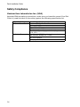
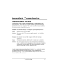
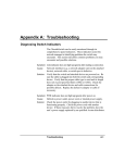
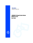
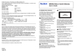
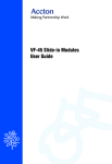
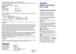
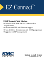
EZ Connect
™
USB/Ethernet Cable Modem
• Complies with DOCSIS 1.0 cable modem
requirements
• Concurrent USB and Ethernet support
• Up to 40Mpbs downstream and 10Mbps upstream
• Supports SNMP management
Quick Install Guide
SMC8002CM-US
Contents
Introduction
Key Features
1
1
Description of Hardware
LED Functions
2
3
Installing the Modem
Package Contents
Mounting the Modem
System Requirements
Connecting the Modem
Installation
USB Installation for Windows 98, Window 2000 and Windows Me
Ethernet Installation for Windows
Windows 95/98/NT
Windows 2000
Making a Connection to the Ethernet Port
3
3
4
4
5
6
6
6
6
6
7
Product Specifications
General Specifications
Physical Characteristics
8
8
8
Troubleshooting
Cannot Connect to the Internet
10
10
Port and Cable Assignments
Straight-Through Wiring
Crossover Wiring
11
12
12
EMI Certification
FCC Class B Certification (USA)
Canada Department of Communications - Class B
CE Mark Declaration of Conformance
13
13
13
14
Safety Compliance
Underwriters Laboratories Inc. (USA)
15
15
Warranty
16
i
Contents
ii
Introduction
The EZ Connect Cable Modem provides high-speed Internet access over the the same
cable network system that brings cable TV service to the home. The data
transmission rate on the cable connection is asymmetric, in that it provides a higher
data rate in the downstream (receive) direction than in the upstream (transmit)
direction. Asymmetric operation is ideal for typical home and small office use where
files and information are downloaded more frequently than uploaded. This modem
has a USB connection which provides plug and play installation, and an Ethernet
connection that allows you to connect up to 16 computers with the use of an
Ethernet hub.
Key Features
• High-speed Internet access over a cable network system
• Data rate of up to 10 Mbps upstream and 40 Mbps downstream
• Always-on digital connection eliminates dial-up delays, and provides transparent
reconnection when initiating any network request
• Operation with cable suppliers is ensured by DOCSIS compliance
• Enhances security with DES data encryption
• Supports Windows 98, Windows 98 Second Edition, Windows 95, Windows NT
4.0, Windows Me and Windows 2000
• Supports up to 16 users through Ethernet connection
• Delivers USB plug-and-play installation and configuration
1
Quick Installation Guide
Description of Hardware
The SMC8002CM-US is an external DOCSIS-based cable modem product for high-speed
Internet access applications.The modem provides an optional USB or Ethernet
connection to a PC or LAN. In an Ethernet LAN environment, it supports up to 16
PCs, allowing shared Internet access.
The following figure shows the components of this modem:
PWR LINK
ACT
STS
Status LEDs
POWER
CABLE IN
RESET
Power Socket
Cable Connector
2
USB
ETHERNET
USB Port
RJ-45 Port
Installing the Modem
LED Functions
The EZ Connect Cable Modem contains four LEDs on the top panel. The operational
status of the modem is indicated by the LED conditions listed below.
LED
Status
Description
PWR
On Red
Power is being supplied to the modem.
LINK
On Green
Indicates a valid 10/100Mbps Ethernet link.
ACT
On Green
Indicates that the modem is receiving data from the
service provider.
STS
Off
Indicates that the modem is starting up and searching
for an available channel to use to transmit data to the
service provider.
Flashing Green
Indicates that the modem is attempting to establish a
connection to transmit data to the service provider.
On Green
Indicates that the modem is online and fully
operational
Installing the Modem
Before installing the modem, verify that you have all the items listed under “Package
Contents”. If any of the items are missing or damaged, contact your local SMC
distributor. Also, be sure you have all the necessary tools and cabling before
installing the modem
Package Contents
This package includes:
•
•
•
•
1 EZ Connect Cable Modem (SMC8002CM-US)
1 switch stand
• This Quick Installation Guide
1 driver diskette
• power cord
1 USB modem cable (modem to
• Owner registration card
computer)
3
Quick Installation Guide
Mounting the Modem
ETHERNET
The SMC8002CM-US comes with a slot-in stand with which it may be mounted vertically or
horizontally. To do this, simply slide the modem on to the stand with the flanges
provided on the base or the side. The two mounting options are illustrated below.
POWER
CABLE IN
RESET
USB
RJ-45 Port
USB Port
Cable Connector
Power Socket
Status LEDs
Flanges
Slot-in stand
System Requirements
The SMC8002CM-US requires the following PC features to operate:
• For USB connection:
A PC equipped with a USB port
-
Windows 98, Windows 98 SE, Windows Me or Windows 2000
• For Ethernet Connection:
A PC with a 10/100 Mbps Ethernet adapter card installed
-
4
Windows 95 or later, Windows NT 4.0 or later
Installing the Modem
Connecting the Modem
Before connecting the EZ Connect Cable Modem, contact your cable service provider
and check the following points:
• Be sure that your service provider supplies a two-way data link.
• Check that they have set up an Internet Access Account. To do this you will need
to provide information that may include the product number and the modem MAC
address. You will find this information on the label on the base of the modem.
The modem must be correctly connected to the service provider’s cable jack. If you
are connecting both a TV and the modem to this outlet, you will need to use a
splitter. The splitter duplicates the signal onto a second wire.
1.
2.
3.
Connect a 75-ohm coaxial TV cable between the splitter and the cable
connector at the back of the modem. Ensure that you do not bend the center
wire of the connector. Tighten both connectors by hand.
Connect the modem to a surge-protected power source.
Connect the modem:
-
to a computer using the USB connection. (See “USB Installation for
Windows 98, Window 2000 and Windows Me” on page 6.)
or
4.
to a computer or Ethernet hub/switch using the Ethernet connection. ( See
“Making a Connection to the Ethernet Port” on page 7.)
The diagram below shows a typical computer/TV installation.
Cable TV Jack
Splitter
AC Power Outlet
Power Cord
PC
Cable Modem
TV
75-ohm coaxial cable
USB or Ethernet Connection
5
Quick Installation Guide
Installation
USB Installation for Windows 98,
Window 2000 and Windows Me
1.
2.
3.
4.
Insert the square (B-type) USB plug
of the USB cable into the USB port at
the back of the modem and the
rectangular (A-type) USB plug into
USB Port
the USB port at the back of the
computer.
The “Found New Hardware” screen
will appear. Insert the driver disk.
When prompted for the location of a
driver, enter the drive letter of your
floppy disk drive.
Follow the instructions given to install the driver.
Reboot your computer when prompted.
R
CABLE IN
RESET
USB
ETHERNET
USB Cable
(provided)
Ethernet Installation for Windows
To connect the EZ Connect Cable Modem to a computer through the Ethernet port, the
computer must have an Ethernet network adapter card installed, and be configured
for TCP/IP protocol.
Carry out the following steps to check that the computer’s Ethernet port is correctly
configured.
Windows 95/98/NT
1.
2.
3.
4.
5.
6.
Select Start/Settings/Control Panel.
Click on the Network icon.
For Windows NT, click the Protocols tab.
Select TCP/IP from the list of network protocols, this may include details of
adapters installed in your computer.
Click on “Properties”.
Select the option “Obtain an IP Address”.
Windows 2000
1.
2.
3.
4.
5.
Select Start/Settings/Network and Dial-up Connections.
Click on “Local Area Connections”.
Select “TCP/IP” from the list of network protocols, this may include details of
adapters installed in your computer.
Click on “Properties”.
Select the option “Obtain an IP Address”.
Your service provider will now be able to automatically assign an IP address to your
computer.
6
Installing the Modem
Making a Connection to the Ethernet Port
You can use straight-through
twisted-pair cable to connect the
Ethernet port on the modem to a PC.
1.
2.
Network Adapter Card
Make sure you have installed a
10/100Mbps network adapter card in
the PC.
Prepare straight-through shielded
“straight through”
or unshielded twisted-pair cables
Cat 3, 4, or 5
with RJ-45 plugs at both ends. Use
UTP Cable
100-ohm Category 3, 4 or 5 cable
for this 10 Mbps Ethernet
connection.
Connect one end of the cable to the
RJ-45 port of the network interface card, and the other end to the Ethernet port
on the modem. When inserting an RJ-45 plug, be sure the tab on the plug clicks
into position to ensure that it is properly seated.
N
RESET
3.
USB
ETHERNET
Caution: Do not plug a phone jack connector into any RJ-45 port. Use only twisted-pair
cables with RJ-45 connectors that conform with FCC standards.
Notes: 1. When connecting to a hub or switch use crossover cabling. (Refer to “Port
and Cable Assignments” on page 10 for a description of crossover cable.)
2. Make sure each twisted-pair cable does not exceed 100 meters (328 feet).
7
Quick Installation Guide
Product Specifications
General Specifications
Standards Conformance
DOCSIS 1.0, IEEE 802.3, IEEE 802.3u, USB 1.1
Cable Modem Requirements
Modulation
Downstream: 64-QAM/256-QAM (receive)
Upstream: QPSK/16-QAM (transmit)
Data Rate
Downstream: 30.432 Mbps (64-QAM), 42.88 Mbps
(256-QAM)
Upstream: 320, 640, 1280, 2560, 5120 kbps (QPSK),
640, 1280, 5560, 5120, 10240 kbps (16-QAM)
Frequency Range
Downstream: 91 MHz ~ 857 MHz
Upstream:5 MHz ~ 42 MHz
Bandwidth
Downstream: 6 MHz
Upstream: 200 kHz, 400 kHz, 800 kHz, 1.6 MHz,
3.2 MHz
Input Signal
Single Channel: -15 dBmv ~ +15 dBmv
Total: < +30 dBmv
Output Signal
+8 dBmv ~ +58 dBmv (QPSK)
+8 dBmv ~ +55 dBmv (16-QAM)
Media Connection
USB cable connection to PC: 90-ohm shielded USB
cable, max length 5 m (16 ft)
Ethernet 10BASE-T: Cat 3, 4, or 5 UTP cable
F-type female 75-ohm connector to CMTS provider
PC Requirements
Host Interface
USB Specification 1.1 or up
System Requirements
USB: Windows 98, 98 Second Edition, Windows Me or
Windows 2000
Ethernet: Windows 95 or higher,
Windows NT 4.0 or higher
Physical Characteristics
Ports
LEDs
Dimensions
Weight
Input Power
Power Consumption
Environmental
Temperature
Humidity
Certification
Immunity
Emissions
Safety
8
1 USB Type-B USB spec. 1.1 (modem to PC)
1 RJ-45 10BASE-T Ethernet (modem to PC, or to
Ethernet, hub/switch)
1 F-type female 75-ohm connector (to CMTS provider)
Power, LINK, ACT, STS
220 x 183 x 55 cm (8.66 x 7.20 x 2.16 in.)
700 g (24.69 oz.)
110 V, 60 Hz
12 Watts maximum
- 40 ~ 45 °C/ -40 ~ 113 °F
10- 95% (noncondensing)
EN 61000-4-2/3/4/5/6/8/11
FCC Class B, CISPR Class B, EN 61000-3-2/3
UL, CB
Troubleshooting
Troubleshooting
Cannot Connect to the Internet
• Confirm that you have established an account with your service provider and that
a two-way cable service is provided.
• Check that all cables are connected to the modem and PC. Verify that the proper
cable type is used and its length does not exceed specified limits. Check the cable
connections for possible defects. Replace the defective cable if necessary.
• Verify that the modem and computer are powered on.
•
•
•
•
•
If the power source has a switch, ensure that it is switched on.
Check the power outlet by plugging in another device that is functioning properly.
Check the power cord with another device.
Power off the modem, wait for 20 seconds and then power back on.
Close down your computer, power off, wait for 20 seconds, power back on, and
then re-boot.
• For USB connection:
Check that the USB driver is correctly installed see “USB Installation for
Windows 98, Window 2000 and Windows Me” on page 6.
• For Ethernet connection:
If the Link LED on the network adapter’s bracket does not light, check the
following items..
-
Check that your computer is properly configured for TCP/IP see “Ethernet
Installation for Windows” on page 6.
-
Make sure the UTP cable type complies with IEEE 802.3 Ethernet, or IEEE
802.3u standards for the type of network you are using. Also, make sure
cable lengths are within the requirements specified. (See “Making a
Connection to the Ethernet Port” on page 7.)
-
Inspect all network cables and connections. Make sure the network cable
is securely attached to the network adapter’s connector.
-
Make sure the correct network card driver is installed for your operating
system. If necessary, try reinstalling the driver.
-
Make sure the computer and other network devices are receiving power. If
you suspect a power outlet to be faulty, plug another device into it to verify
that it is working.
-
If the the network adapter’s speed or duplex mode has been configured
manually, check that it matches that of the attached network device port.
Note that it is recommended to set the adapter to auto-negotiation when
installing the network driver.
9
Quick Installation Guide
Port and Cable Assignments
Caution: DO NOT plug a phone jack connector into any RJ-45 port. Use only
twisted-pair cables with RJ-45 connectors that conform with FCC
standards.
An Ethernet twisted-pair link segment requires two pairs of wires. Each wire pair is
identified by two different colors. Each wire pair must be attached to the RJ-45
connector in a specific orientation detailed below.
The Ethernet port on the modem is an MDI-X port, which allows straight-through
cable connections to PCs, and to hubs and switches with MDI ports. In
straight-through cable, pins 1, 2, 3, and 6, at one end of the cable, are connected
straight through to pins 1,2, 3 and 6 at the other end of the cable. For connection to
hubs or switches which have MDI-X ports, a cross-over cable must be used.
Pin
10
MDI-X Signal Name
MDI Signal Name
1
Receive Data plus (RD+)
Transmit Data plus (TD+)
2
Receive Data minus (RD-)
Transmit Data minus (TD-)
3
Transmit Data plus (TD+)
Receive Data plus (RD+)
6
Transmit Data minus (TD-)
Receive Data minus (RD-)
4,5,7,8
Not used at 10 Mbps
Not used at 10 Mbps
Port and Cable Assignments
Straight-Through Wiring
If the twisted-pair cable is to join two ports and only one of the ports has an internal
crossover (MDI-X), the two pairs of wires must be straight-through.
Straight-Through RJ-45 Pin Assignments
End 1
End 2
1 (RD+)
1 (TD+)
2 (RD-)
2 (TD-)
3 (TD+)
3 (RD+)
6 (TD-)
6 (RD-)
Crossover Wiring
If the twisted-pair cable is to join two ports and either both ports are labeled with an
“X” (MDI-X) or neither port is labeled with an “X” (MDI), a crossover must be
implemented in the wiring.
Crossover RJ-45 Pin Assignments
End 1
End 2
1 (TD+)
3 (RD+)
2 (TD-)
6 (RD-)
3 (RD+)
1 (TD+)
6 (RD-)
2 (TD-)
11
Quick Installation Guide
EMI Certification
FCC Class B Certification (USA)
This device complies with Part 15 of the FCC Rules. Operation is subject to the
following conditions:
1.
2.
This device may not cause harmful interference, and
This device must accept any interference received, including interference that
may cause undesired operation.
Warning: This equipment has been tested and found to comply with the limits for a
Class B digital device, pursuant to Part 15 of the FCC Rules. These limits are
designed to provide reasonable protection against harmful interference in a
residential installation. This equipment generates, uses and can radiate radio
frequency energy and, if not installed and used in accordance with the instructions,
may cause harmful interference to radio communications. However, there is no
guarantee that interference will not occur in a particular installation. If this equipment
does cause harmful interference to radio or television reception, which can be
determined by turning the equipment off and on, the user is encouraged to try to
correct the interference by one or more of the following measures:
• Reorient or relocate the receiving antenna
• Increase the separation between the equipment and receiver
• Connect the equipment into an outlet on a circuit different from the one which the
receiver is connected to
• Consult the dealer or an experienced radio/TV technician for help
You are cautioned that changes or modifications not expressly approved by the
party responsible for compliance could void your authority to operate the equipment.
Note: In order to maintain compliance with the limits of a Class B digital device, SMC
requires that you use a quality interface cable when connecting to this device.
Changes or modifications not expressly approved by SMC could void your
authority to operate this equipment. Suggested cable type is unshielded or
shielded (UTP/STP) cable – Category 3 or greater for 10 Mbps connections.
Canada Department of Communications - Class B
This digital apparatus does not exceed the Class B limits for radio noise emissions
from digital apparatus as set out in the interference-causing equipment standard
entitled “Digital Apparatus”, ICES-003 of the Department of Communications.
Cet appareil numérique respecte les limites de bruits radioélectriques applicables
aux appareils numériques de Classe B prescrites dans la norme sur le matériel
brouilleur: “Appareils Numérques”, NMB-003 édictée par le ministère des
Communications.
12
EMI Certification
CE Mark Declaration of Conformance
This information technology equipment complies with the requirements of the
Council Directive 89/336/EEC on the Approximation of the laws of the Member
States relating to Electromagnetic Compatibility and 73/23/EEC for electrical
equipment used within certain voltage limits and the Amendment Directive 93/68/
EEC. For the evaluation of the compliance with these Directives, the following
standards were applied:
RFI
•
Emission: •
•
Immunity: •
Limit class B according to EN 55022:1998
Limit class A for harmonic current emission according to EN 61000-3-2 1995
Limitation of voltage fluctuation and flicker in low-voltage supply system
according to EN 61000-3-3/1995
Product family standard according to EN 55024:1998
•
Electrostatic Discharge according to EN 61000-4-2:1995
(Contact Discharge: ±4 kV, Air Discharge: ±8 kV)
•
Electrical fast transient/burst according to EN 61000-4-4:1995
(AC/DC power supply: ±1 kV, Data/Signal lines: ±0.5 kV)
•
Surge immunity test according to EN 61000-4-5:1995
(AC/DC Line to Line: ±1 kV, AC/DC Line to Earth: ±2 kV)
•
Immunity to conducted disturbances, Induced by radio-frequency fields:
EN 61000-4-6:1996
(0.15 - 80 MHz with 1 kHz AM 80% Modulation: 3 V/m)
•
Power frequency magnetic field immunity test according to
EN 61000-4-8:1993 (1 A/m at frequency 50 Hz)
•
Voltage dips, short interruptions and voltage variations immunity test
according to EN 61000-4-11:1994 (>95% Reduction @10 ms, 30%
Reduction @500 ms, >95% Reduction @5000 ms)
Warning! Do not plug a phone jack connector in the RJ-45 port. This may damage
the device. Les raccordeurs ne sont pas utilisé pour le système téléphonique!
13
Quick Installation Guide
Safety Compliance
Underwriters Laboratories Inc. (USA)
Important! Before making connections, make sure you have the correct Cord Set.
Check it (read the label on the cable) against the following specification list.
Operating Voltage
120 Volts
240 Volts (Europe only)
14
Cord Set Specifications
UL Listed/CSA Certified Cord Set
Minimum 18 AWG
Type SVT or SJT three conductor cord
Maximum length of 15 feet
Parallel blade, grounding type attachment plug rated
15 A, 125 V
Cord Set with H05VV-F cord having three conductors
with minimum diameter of 0.75 mm2
IEC-320 receptacle
Male plug rated 10 A, 250 V
Warranty
Warranty
SMC warrants to the original owner that the product delivered in this package will
be free from defects in material and workmanship for a period of three (3) years from
the date of purchase from SMC or its Authorized reseller. For the warranty to
apply, you must register your purchase by returning the registration card indicating
the date of purchase and including proof of purchase. There will be a minimal
charge to replace consumable components, such as fuses, power transformers, and
mechanical cooling devices. The warranty does not cover the product if it is
damaged in the process of being installed. SMC recommends that you have the
company from whom you purchased this product install it.
THE ABOVE WARRANTY IS IN LIEU OF ANY OTHER WARRANTY, WHETHER
EXPRESS, IMPLIED OR STATUTORY, INCLUDING BUT NOT LIMITED TO ANY
WARRANTY OF MERCHANTABILITY, FITNESS FOR A PARTICULAR PURPOSE,
OR ANY WARRANTY ARISING OUT OF ANY PROPOSAL, SPECIFICATION OR
SAMPLE. SMC SHALL NOT BE LIABLE FOR INCIDENTAL OR
CONSEQUENTIAL DAMAGES. SMC NEITHER ASSUMES NOR
AUTHORIZES ANY PERSON TO ASSUME FOR IT ANY OTHER LIABILITY.
15
FOR TECHNICAL SUPPORT, CALL:
From U.S.A. and Canada (24 hours a day, 7 days a week)
(800) SMC-4-YOU; (949) 679-8000; Fax: (949) 679-1481
From Europe (8:00 AM - 5:30 PM UK Time)
44 (0) 118 974 8700; Fax: 44 (0) 118 974 8701
INTERNET
E-mail addresses:
[email protected]
[email protected]
Driver updates:
http://www.smc.com/index.cfm?action=tech support drivers downloads
World Wide Web:
http://www.smc.com/
http://www.smc-europe.com/
FOR LITERATURE OR ADVERTISING RESPONSE, CALL:
U.S.A. and Canada:
Spain:
UK:
France:
Italy:
Benelux:
Central Europe:
Switzerland:
Nordic:
Northern Europe:
Eastern Europe:
Sub Saharan Africa:
North Africa:
Russia:
PRC:
Taiwan:
Asia Pacific:
Korea:
Japan:
Australia:
India:
(800) SMC-4-YOU;
34-93-477-4935;
44 (0) 118 974 8700;
33 (0) 41 38 32 32;
39 02 739 12 33;
31 33 455 72 88;
49 (0) 89 92861-0;
41 (0) 1 9409971;
46 (0) 868 70700;
44 (0) 118 974 8700;
34 -93-477-4920;
27-11 314 1133;
34 93 477 4920;
7 (095) 290 29 96;
86-10-6235-4958;
886-2-2659-9669;
(65) 238 6556;
82-2-553-0860;
81-45-224-2332;
61-2-9416-0437;
91-22-8204437;
Fax (949) 679-1481
Fax 34-93-477-3774
Fax 44 (0) 118 974 8701
Fax 33 (0) 41 38 01 58
Fax 39 02 739 14 17
Fax 31 33 455 73 30
Fax 49 (0) 89 92861-230
Fax 41 (0) 1 9409972
Fax 46 (0) 887 62 62
Fax 44 (0) 118 974 8701
Fax 34 93 477 3774
Fax 27-11 314 9133
Fax 34 93 477 3774
Fax 7 (095) 290 29 96
Fax 86-10-6235-4962
Fax 886-2-2659-9666
Fax (65) 238 6466
Fax 82-2-553-7202
Fax 81-45-224-2331
Fax 61-2-9416-0474
Fax 91-22-8204443
If you are looking for further contact information, please visit www.smc.com or
www.smc-europe.com.
38 Telsa
Irvine, CA 92618
Phone: (949) 679-8000
Model Number:
SMC8002CM-US
Publication Number: 150200006400A
Edition Number:
E022002-R01 F1.0