1
oj aais aq sfem@ isw -a^'iamj/jaSSt~i~IU.-UOQ!SO<*
.UQ, u! aAim ,YOPO, am "w' a m 'eedei '1(001101,1 oa
ws op 01 peuiw suos~adAq
iw pa!Jjeo aq AIUO pinoqs mjedai pue 6up!i\~&s
x~@w
"wfeda~
Ai~~oduist
e m JO &S!AOJ~W!iou OQ ¥J(~È~
pue e3UEUe$U!Bul 101 s w d &reds 33a~iooAluo ~ s r ->
-du&i=
-
KM on -WMWft
loolwa~aans~Aeu;i^m^aKaucaaeeiAwaaca
-.ma at Aim A&u&iagirisi ~ 6t8
a da5 w wl!çA00(
/PUB SUROOJUUy zz id0W '100) 844 6tt!m USYM dettiv
'Ayaiiiiaaia
1 L)~!M
isqnoa olu! 6u!uoo $0 saueya h e si QJ9W 11
1004 sift asn J&AaN-pai~insfi
Ajlmppa~aiou s! fw^ a u
-loot am 01 p w i ~ U W
KKWS SMIEU SIB &emwed
-
-t~peue
BUMJCMH
cut WJI
pue ^poq eig d->s
' W t 9^Suge)s<to U
W
~aw
m ^Èa[wtfliiqro~estwo
1tw0~~t~)eaaiatp
suf?iuo9 settifttlo~uo!iotu1suoo J@U$O
pue ' 6 u ! l ~ ~ p
-
'BuipuyG '(Suwe~
'Buptm ~0ModAq meanp n p
'p8pU~WO3alSB )ueuid!nbe u o @ w ~ o[euos~ad
~d
asn
.wn^s&~d
JÈI fiunuo~
~unuiveuiq peeoxa jou
%sjwAlepzs 8sau
33pUe Ès si! U!
+jOOl
~ ! S B
-&ti@!
@#V32
--
-YOâ
-8
SYOiptuiSUf
01
JSSM
.
'
-sped aua~kdlodesn )ou OQ
' ~ 9 p ~ yE 6S@ esn IOU O a Jepues
-
-%ILC1
ON
oe-t
mtoi~auej89
iynuÈui^-$2;t
%IOQsOHi^puautuioosH
,
.israu ~a0ieisd0
#$Y
$iW
83048q
PESY few liogaiqy WlsorfYB pa6uQaiid -itsew 6ufui8e~q
e we 5856606 4 a p s
sfe~iv
-w<ty 000'0 i e w e patw sapme3:)e asn IOU od
VW9S e hi= uai^w s a w Ai^w
-
..-..m!&IJS
, ,,-
NO1
win &SOH
wyipapuaaayo3$y
^M^/A~wPCiOOLtd
^Qm("i
PSPU9UIIll~Y
I
1
Work Stations
return to the 'Off' position when released.
-Always shut off the air supply to the toot and press tha
*On/Off' vatro to 'exhaust thà air from the feed hose
before B a n g , f-ng
or adjusting the working
attachment fitted to the tool.
-Before using tha too), make sure that a. shut off device
has been fitted to the air supply fine and the position is
known and easily accessible so that the air stippiy to
The too;sfwutsi on!y be used as a handheld, hand operatedtoot.It
isawieewtsaartdgdSateÈioofisasedtAessteBicfeaw
solaftw-&can
tà u$&insawpositions. but beforeany -suctt
use, the operator must be ft) a secure position having a finn grip
and tooting and be aware of the safety rules to be obsysd when
using the sander.
ihetootcanfeeshuEoffI#anç(ne^e~~y
-Check ho^e and tittings reguSarty for wear.
-Take care against entanglement of the moving parts' of
the tool wHh clothing, hair. ties, cleaning lags, rings,
jewelry, watches, b,-ac6tebretc. This could cause the
bodyorpartsof8abodytob&drawntowaRisanstIn
contact with ihe moving parts of the toof and 4 6 be
very dangerous.
-It is expected that users wilt adopt safe worxing
practices and observe all local, regional and country
tegat requirements when instaiting, using or
raatntainittQthe tod,
-Take care that the exhaust air does not point towardte
any other parson or material or substance that could
be contaminated by oil droplets. When first lubricating
a toot or if ttw toot exhaust has 3 high oil content, do
not allow the exhaust air to come near very ftoi
surfaces or flames.
-Never lay the tool down until the worWng attachment
has stopped moving.
-When the toot is not in use, shirt oft ttÈ air supply and
pressthetrigg&^!~wto<facanfeesupptytine.BBte
tool is not to be used for Ãperiod of time, first iubricate,
disconnect from air supply and store \r\ a dry average
room temperature environment.
-If the tool is passed f r m one user to a new w
inexperienced user, make sure these (nstrucSons are
passedwiththatoot
-Do not remove any manufacturer fitted safety devices
where fitted, i-e., wheel guards, safety trigger, speed
governors?,etc.
-Wherever possible, secure workpiice with clampst a
viss,etc.tomaisait rig(<iisoSdoesRotwwe&RngW
work opefaSon. Keep good balance at a11 times. Do not
stretch or overreach.
Try to match the too)to the work operation. Do notuse
a loot thai is too light or heavy for the work operalion. If
in doubt sesk advice.
-In genera.) terms, this toot is not suitable for
underwater use or use in wpbsive wivlronmente
seek advice from manufacturer.
-Try to make sure that the work area is clear to enable
the work task to be performedsafeiy- if practical ansi
possifcis.try to clear unnecessary obst(uc8ons before
starting work-Always use ah hose and couplings with minimum
working pressure ratings at least 1 112 times the
maximum working pressure rating of Ihe toot.
-
-
-
Foreseen Use Of The~ool 5558A
This toot is &signed tor the purpose of c
s
ia
m or sanding at a
vanetaoffnataffetstaaistfeawtai,wswt.sSasfessateiais,^C.
TtÈdualrotaryofbttatacCortwSwasttwamurtoisbrssiv
EpncNng mites and hence Is primarily a finishifig sanding toot. It
can be used wfth a variety of grades of 150 mm (6'diameter)
abrasive discs whichr according to pad fitted to the tori, can be
so#adhesive çVefctoA$atiiwf,
Dowstusemtoriferanyot&er~tothaifarw^ahas
(wendesigned and use only abrasive discs as clesenbed.
Putting Into Service
Air Supply
Use a dean lubricated air supply that will give a measured air
piesswe at the tool o<SO p.aiJ4.2 bat when 9w too*is wnning
wflhtne{Bg3e-la8sf<iepresse<f.Use;'ee6ffHwffite<itosestzs
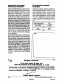
and SstPQ'&i. ti is reaanffiewieti that the toot is connected to the air
supply as shown in fiaure 1. Do not connect the tod to the atr line
systtsm without incorporatingan easyto reach and operate air shut
off valve. The air supply should be lubricated. I1 (S strongly
recwiffien(fediftat an ate fatar, rsguiator, lubffcaiar (FRL} useti
as stiow> inFfgare3 as ftis wB s^rfy aft
itj&iteitefi
,
aif at*
coffeet pressure to the toot. Details & such equipment can be
obtained from your supplier. If such equipment IS rtot used, then
the tool should be I i A h t e d by shuttimi off the air supply to the
tool, depressuriang ths fine by pressing the triggetAewr on the
tool Clfeeonnact Iià ak iine ansi
ffiio me Rose adaptor s
ie.tsp(Ènhi &m$
! of a suitafcfe W d s a f e msiw (liBncating 041
profBmMy incorporating a fust mhibftor. Reconnect loot to air
supply and run tool slowly lor a few seconds to allow air to
circulate the oil. if too) is used frequently. lubricate on daily basis
and if tool starts to stow or tose power,
KisteeMwtentisi!8*attfeeairpressa#at8iatwi¥sitsiteiheto<^E
furwiw fe 60y6iS42 bar.
Operating
Setectasiat^xaabi^arodisc<seeSaefen'F<ws^nUteaotTooT)
amtatsAftsweftatBisteedssxwstftothetool.Conwcttos~
air sufifty as reconnmeoded.
Appty 8Ã saoder lightly to ttie work aftd allow the abtasiw doc to
wLTate great care when sand"mgaroundsharpedges and surfaces
toaw4dthecfiscsna~~i.e.thediscmay
bebroughttoanabrupt
ssspwcwUSsssSiSy^cwedwhichwScausettÈtoottote*fe^
hati&- It !s &ways ifacof~resflddto use safely gtaasfis and a
breathing mask. The sanding of certain materials may create a
hazarcfous dust which may require m
a
\
breathing equipment.
Ctwck before using the tool. Even 9 tte machine has a b w noise
leva!,theactualsandfcw~ass~isauseanoisel&such~r
earcratectefswl!feefcauirad.ESwearesfsTpwsaonShe
mteiiatixSag sanctet!" safety ffews Wts recomerKieA
Do not cortinueto useatwastve dim that are worn or dogged. Ttife
win make the sanding process heffteiwit and the need to apply
unnecessarilyhighfcrcostothetoot.
DorwtusawxiasiradorfHwsizedmtSscs.TBe<i6scshouki
&emfflt~e8Èat1/4'iamis(iiafnaerSwiaÈ{arfand#staff
ttanttropad.hairwgutalorlever(42)tehxaiedm(heisxteofttÈ
bo~(16).Itcanbeusedtovarythevolume<rfcompressed~rfedto
the motor which wilt vary the speed of the saoder.
AnairstrainerisinowporatediitintetbuSt&w.TWsstioutdbecheewct
pef*xttea9tf*rSetrfartyiffhstoo!sfewsorlosespowervItcanbe
eas%çteanrfwTOSaciwq&iat3tHi#Èfc?miia(Èdte(58)."ntespBt
lock can be set to provute eittiw rotary or orbital action. Slide the
drtve washer (5)ptate h untB Die point falters the races-s in the pad
mounting shaft (9) for rotary action. The counterweight
balance pCTrades a titoat when which fiwas a smooth,swirt-iree
L
Dismantling & Assembly Instructions
DisewiTOCttoo! from air supply.
RUto*&Èif!sm>eiwBiafceifeie(ito;atÈtioffi&a(ancew<1tl.Pre
the W e dimpie on drive washer (5) to engage the hots in the
Side Of mounting pad shah (9) and unscrew pad [I). Carefully remove the instruction telbof fixed to the random balance bwtv (1 11
Page No 2
spring washer (3). balance nut (4). drive washer (5) wave washer
(6) and then remove retaining ring (7) and wave washer (8). Still
grippingrandom balance body (1 l),tap out mountingpad shaft (9)
assembly at the rear end to remove the assembly from the random
balance body with wave washer (15). Remove fixing screw (14)
from pad mounting shaft (9) and tap this pad mounting shaft (9)
through bearing (10).
Remove two screws (38) and take off motor cover (49). Grip body
(16) in a vise fitted with soft jaws and remove four rotor screws
(31) and take off rotor cover (29). From the front end of the tool, tap
the end of rotor shaft (18) to drive the motor assembly out of the
body (16). Note how the slot in the side of the cylindei(26) has to
line up with the port in the body (16). Grip rear plate (28) and tap
the rear end of the rotor shaft (18) through the rear plate (28) and
bearing (24). Remove rotor blades (23), shims (20). and unscrew
set screw (22) from rotor (21) and remove rotor shaft (18). Note
location of set screw (22) hole in rotor (21) in position with flat on
rotor shaft (18) and remove shims (20). Tap front end of rotor shaft
(18) through front plate (17) to remove bearing (19) fromfront plate
(17). Unscrew cap screw (32) and take out throttle spring (33).
push rod (45). and O-ring (34). Do not remove valve body bushing
(46) from body (16).Take off retaining ring (35), remove plate washer
(36)and rubber washer (37). Remove screw (44) and lock washer
(43). Pull off regulator lever (42) and O-ring (41). Carefully pull out
regulator (40) with two O-rings (39). Unscrew bolt (53) from nut
(54) and take off safety lever (52). Take out two screws (50) and
remove lever bracket (51). Remove handle grip (57) and unscrew
handle (58) from body (16) and take off valve lever (55). Remove
muffler (47) and muffler element (48) trom motor cover (49).
Notes
Reassembly
Clean all parts and examine for wear. Use only manufacturer or
authorized distributor supplied spare parts and replace any worn
parts. Look in particularfor wear on seals, ball bearing and blades.
Coat all parts in pneumatic tool lubricating oil, and reassemble in
the reverse order carefully. Assure all parts are tight and let lever
and regulator mechanisms operate freely. With (ever depressed,
pour 5 mi of a suitable pneumatic tool oil into inlet bushing and
release. Connect a suitable air supply and run this tool for 2 or 3
seconds to allow the oil to circulate.
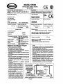
Operation Specification
Average Air Consumption
Air Inlet Thread
4.0 d m (28 scfm)
Spindle Thread
5116-24UNF
t
114-18NPT
Length
8" (204mm)
Height
5.4" (136mm)
Pad
6" (150mm)
I
1
at 60 PSIGl4.2 bar
I.
r
cc
Declaration of Conformity
Sioux Tools Inc.
117 Levi Drive, Murphy, NC 28906, U.S.A.
declare under our sole responsibility that the product
Model 5558A 6" Dual Action Sander, Serial Number
to which this declaration relates is in conformity with the following standard(s) or other normative document(s)
EN792 (Draft), EN292 Parts 1 & 2, IS0 8662 Parts 1 & 8, Pneurop PN8NTC1
following the provisions of
89139ZEEC as amended by 91/368/EEC & 93144fEEC Directives
&
f A L
.
G a
Seebeck (President)
Page No 3
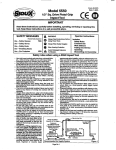
Modhle 5558A
Fonceuse a action double
de 150 mm
Important
Usez atlefitivenwnl ces Instructions avant d'instalk, He faire
foncttoniw, d'Bfltretenir ou de -rer
cet outil. Gardez ces
Sioux Tools, Inc.
117 Levi Drive
Murphy, NC 28906
US.A.
Tel No. 828-835-9765
Poids net du produit
1,97 kg
Type de produit
Tours par
Ponceuse 3 action
double de 150 m m
t/rnm
c?
Fax No. 828-835-9685
Emploi conseille (fun
d i i t i f d'6quilibrage ou
d'un support.
NON
-
k g e de fuyau fecornmandd
Taille minimum
8 mm
-
-
Longueur maximum de
tuyau recommand&
10 m
-
Niveau sonore:
Niveau de pression sonore 79,O dB (A)
Pression (fair
De fonctionnement
recornmand6e
4,2 bar
Maximum
4,2 bar
M6thode de test: Test6 selon Ie code de test
Pneurop PN8NTC1 et la norme IS0 3744.
Niieau de vibrations
3,7 m/s2
M^thode de test test4 selon les normes IS0
8662, sections 1 & 8
Test6 sous line pression #air de 4,2 bar
St i'out1 doit 6tre employe avec un cfisposftif d'huilibrage
ou da suspension,assurez-vousoue I'outjtesi henfixa ace
-
N'empkye~ de ptateaux en polystyrene.
N'erndwez oue des accessoires d'une puissance
nominalesup6fteurea 10.000 trAnin.
11 hutotporter des lunettesde security et m masque
respiratoire.
Une exposition p(Olong6eawevibrations peut causer des
Measures.
Usez tes instructions avant demployer cet outiL Tous Ie
operateurs d d w ? connaHre pariaftemenl son uliBsation
ponqage, Ie sciage. Ie meulage, Ie
percage pneumatique et d'autres
activites de construction contiennent
des produits chimiqms qui sort connus
comme provoquant Ie cancer, des
anomalies cong6nitales et d'airtres
troubles reproductifs.
Ernployezseufementde Pair compreno
dans les conditions r e c q m a d h
Q ~ I C vous
I
employe2routi~,
ten& toutours~ecorps et 18s
mains & I'Acart des accessoires de travail fix& a foutd.
Cot oulil n'est pas +&6 61ectriquement. N'employez
jamais cet o d si vous risquezd'entrer en contact avec de
l'6tectridt6.
Quadvous employezcetoutil, prenez une position ierrne
et tenez bien I'otitil pour compenser toutes forces de
r&ction quipourraient&tre museespar!%fonctionnement
de I'outit. Ne s q e z pas trop fort dans les mains.
Employe2 settlement des pieces de recbange correctes
pour rentretien et tes reparations. NVimprovisezpas de
fSparaBons tsmporaires. L'entretien et les reparationsne
dotvent &tre effectuees que par du personnelqualie.
Toufktuyauxetoccoids
Prise Cair an m e t
çltwHitavoirindBio6tr
ffw moms 1.27 tin (t/y)
SiFouBsembtematfoncSonnar,an-etez
.immeciatementsonempfaietfailes-te
.
Svstefne tfalimentation {fair recommand4
Page No 4
Fmure 1


![1127117 - [PROJECT.TOC] - Performance Heating & Plumbing](http://vs1.manualzilla.com/store/data/005895106_1-55e9d6c83dbc31a8ba61d6bb401245cf-150x150.png)