1
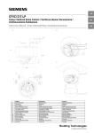
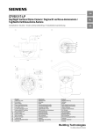
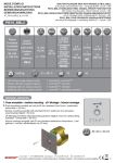
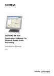
English
Instruction Manual for Day-Night Vandal Resistant Dome Camera
Model number
Modelnummer
Typen-Nummer
CVVS1415-LP
Part Code
Art. code
Art.-Nr
2GF1185-8AE
Accessories / Accessoires / Zubehör
CVVA-CD
2GF1086-8AH
Clear Lower Dome - Vandal Resistant / Nl: Transparante dome vandaalbestendig / De: Transparente Kuppel - Sabotagegeschützt
CVVA-WB
2GF1086-8AD
Wall Bracket / Nl: Muurbeugel / De: Wandhalterung
CVVA-FMK
2GF1086-8AC
Flush Mount Kit / Nl: Kit voor verzonken montage / De: Unterputzmontagesatz
Document / Document / Dokument
Edition / Editie / Ausgabe
Supersedes / Vervangt / Ersetzt
A24205-A336-R534
Rev A.1
-
A
B
15
19
14
1
16
4
18
5
2
3
4
17
5
8
6
7
C
9
2
10
11
3
12
20
13
21
WARNING
WAARSCHUWING
WARNUNG
To reduce the risk of fire or electrical shock, do not
expose this product to rain or moisture.
This installation should be made by a qualified service
person and should conform to all local codes.
Connect the equipment to 12 V DC or 24 V AC UL
Listed Class 2 Power Supply.
The CAUTION label shown above is attached to the
dome.
Stel dit product niet bloot aan regen of vocht, want dat
zou brand of een elektrische schok kunnen veroorzaken.
Het installeren moet door een deskundige technicus en
conform alle plaatselijk geldende voorschriften worden
uitgevoerd.
Sluit de apparatuur aan op een UL-gecertificeerde
voeding van 12 V DC of 24 V AC, klasse 2.
Bovenstaande waarschuwingssticker is op de dome
bevestigd.
Um die Gefahr eines Feuers oder Elektroschocks zu
vermeiden, darf dieses Gerät weder Regen noch
Feuchtigkeit ausgesetzt werden.
Die Installation sollte von einem qualifizierten
Servicetechniker gemäß den geltenden Vorschriften
ausgeführt werden.
Schließen Sie das Gerät an ein Netzteil mit 12 V
Gleichstrom oder 24 V Wechselstrom (UL Class 2) an.
Der Warnhinweis oben ist an der Kuppel angebracht.
English
•
•
•
•
•
•
Dome camera
1 service monitor cable
1 remote PC connection cable (Additional RS232
cable is required to interface to your PC (not
included))
Remote software CD
2 fixing screws
2 wall plugs
Fixing template
Installation and operating instructions (this document)
Screwdriver
Dome camera parts
See figures A, B and C.
1. Cable entry holes
2. Unit casing
3. Dome casing
4. Zoom lever/locking screw
5. Focus lever/locking screw
6. Iris LEVEL screw
7. V phase adjustment screw
8. Mode setting DIP switches
9. PC connection port
10. Monitor output
11. Video connnector - Auto Iris Lens
12. Power connector - Auto Iris Lens
13. Unit mounting holes
14. BNC cable
15. Power cable
16. Locking ring
17. Panning adjustment wheel
18. Axial ring
19. Conduit hole plug screw
20. Security screws
21. Security screwdriver
Caution
Do not turn the lens more than 360°, as this may
cause internal cables to disconnect or break.
4. Lightly tighten the locking ring (16) and panning
adjustment wheel (17)
Step 4: Adjusting zoom and focus
1. Loosen the zoom lever/locking screw (4) by turning it
counter-clockwise.
2. Rotate the zoom ring to achieve the desired picture.
3. Loosen the focus lever/locking screw (5) by turning it
counter-clockwise.
4. Rotate the focus ring to adjust the focus.
5. If readjustment is necessary, repeat the steps above.
6. Retighten the zoom lever/locking screw (4) and the
focus lever/locking screw (5).
Caution
Retighten the locking screws to prevent loss of
adjustment.
7. Hold the lens and tighten the locking ring (16) and
panning adjustment wheel (17).
Optional settings
•
•
•
Installing the camera
Step 1: Connecting the cables
(a) Using the side conduit hole
1. Loosen the conduit hole plug screw (19) on the side
conduit hole. Remove the plug.
2. Connect the BNC cable (14) to the video connector
(11).
3. Connect the power supply cable (15) to the power
connector (12).
You can use 24 V AC or 12 V DC connection.
Caution
If using a DC supply, make sure the polarity is correct.
Incorrect connection may cause malfunction and/or
damage to the video camera.
4. Clean the thread grooves in the bottom conduit hole
and install the removed plug firmly into the bottom
conduit hole to prevent moisture from getting inside
the casing.
(b) Using the bottom conduit hole
The BNC cable and power cable are installed through the
bottom conduit hole (Factory setting). Connect the cables
to the respective connectors (14)(15).
Step 2: Mounting the camera
1. Place the template on the mounting surface and mark
the holes.
2. Drill two holes as marked.
3. Insert the wall plugs into the holes.
4. Fasten the unit with the screws provided.
Caution
To ensure weatherproof rating, prior to fastening the
unit the base of the dome should be completely
sealed with a waterproof silicon to avoid water to
penetrate.
Be careful when installing the pipe /plug in the conduit
hole; the screw part of the pipe /plug must be 12 mm
or less so that it will not damage the inside unit.
Step 3: Adjusting the camera position
1. Hold the lens so that it does not rotate.
2. Loosen the locking ring (16) and panning adjustment
wheel (17).
Caution
Do not loosen the locking ring without holding the lens
in place. Otherwise the lens may rotate with the
locking ring and the cable may twist.
3. Turn the lens and axial ring (18) in the desired direction.
Note
If the camera does not rotate smoothly, loosen the
locking ring completely. The locking ring has an
internal stop and will not come off.
Adjust the brightness of the picture using the Iris
LEVEL screw (6):
L = low, makes the picture darker
H = high, makes the picture brighter
Adjust the phase difference between cameras (use V
Phase adjustment screw (7).
Set DIP switches (8) to activate or deactivate the
following features:
• Backlight compensation (BLC)
• Automatic gain control (AGC).
• Line lock (LL).
Sets camera synchronisation to internal (OFF) or line lock
(ON). Line lock is only available with 24 V AC.
The DC / AES DIP switch is not in use, and is always
set to DC position.
Step 5: Remote PC connection
This camera is equipped with the latest DSP technology.
The remote software kit allows remote access and further
enhances the camera’s usability and functionality.
Please install the remote software onto you PC in
accordance with the "readme" file on the CD.
Note
Please read the camera’s parameters and save them to a file
prior to performing any other adjustments. During this process,
the picture may flicker or distort. This is normal during this
operation and the picture will return to normal once completed.
Additional camera functions include
• Linear AGC gain control (ON: 22dB ~ 30dB;
OFF: 16dB ~ 24dB)
• Pedestal level adjustment (0~9 IRE)
• Predefined BLC fields (6)
• Sharpness (low/mid/high)
• Day/Night transition level (adjustable)
• Image Option (negative/monochrome)
• Read camera parameters
• Write to camera memory
• Restore factory default settings
• Save and reload parameters from file
Step 6: Attaching the dome to the unit
Note
Use a soft, lint-free cloth to wipe the dome cover clean
and remove fingerprints.
1. Clean the joint surfaces of the unit.
2. Place the dome on the unit (see figure C).
3. Match the screws on the dome casing (3) to the
screw holes (3 locations) on the unit casing (2).
4. Holding the dome casing to maintain the matched
positions, tighten the three screws (20) with the
screwdriver (21) and lock the dome casing to the unit
casing.
General guidelines
Operation and storage
•
•
Avoid filming very bright objects (such as light fittings)
for an extended period.
Do not operate or store the unit in the following
locations:
• Extremely hot or cold places.
• Close to sources of strong magnetism.
• Close to sources of powerful electromagnetic
radiation, such as radios or TV transmitters.
• In humid or excessively dusty places.
• Where exposed to mechanical vibrations.
• Close to fluorescent lamps or objects reflecting
light.
• Under unstable or flickering light sources.
Cleaning
•
•
Use a soft, dry cloth to remove fingerprints or dust
from the dome.
If the dome is very dirty, use a small amount of mild
detergent on a damp cloth for cleaning. Ensure the
dome is dry before attaching the dome to the unit.
Caution
Do not use volatile solvents such as alcohol, benzene
or thinners. These solvents may damage the surface.
Transportation
Use the original packing material or materials of equal quality.
CCD characteristics
The following conditions may be observed when using a
CCD camera. These are inherent in the design and do
not stem from any fault in the camera itself.
• Vertical smear: This phenomenon occurs when
viewing a very bright object.
• Patterned noise: This is a fixed pattern which may
appear over the entire monitor screen when the
camera is operated at a high temperature.
• Jagged picture: When viewing stripes, straight lines,
or similar patterns, the image on the screen may
appear jagged.
Specifications
General
Power requirement ..........12 V DC or 24 V AC
Power consumption .........3.5 W (max.)
Operating temperature ....-10 to +50°C, 90% RH max.
Storage temperature........-20 to +60°C, 70% RH max.
External dimensions ........138 x 112 mm
Weight .............................Approx. 1.7 kg
Unit material ....................Aluminium
Dome material .................Polycarbonate
IP Rating ..........................IP66
© 2004 Siemens Building Technologies: Fire and Security Products
•
•
•
Imaging system
Imaging device ................Exview™ Interline transfer
1/4 inch CCD
Effective picture elements.PAL: 752(H) * 582(V)
TV system........................PAL: 2:1 Interlace,
15.625 kHz horizontal,
50 Hz vertical
Optical system and other specifications
Day-Night Mode................Mechanical IR filter (automatic)
Focal length .....................2.8 to 5.8 mm
Maximum rel. aperture.....F1.4
Viewing angle .................Horizontal: 74.7° (wide angle) 35.9° (telescopic)
Vertical: 55.2° (wide angle) 26.9° (telescopic)
Minimum object distance . 0.2 m
Synchronisation system...Internal or Line lock
(24 V AC only)
Horizontal resolution ........480 TV lines
Minimum illumination ........0.34 lx in C/L mode
0.15 lx in B/W mode
(AGC ON, more than 50% of
image output, without dome
cover)
Video output ....................1.0 Vp-p 75 Ohm negative
sync.
Video S/N ratio ................More than 50 dB (AGC OFF,
weighted)
White balance..................Automatic (2500 K - 10000 K)
AGC ..................................ON/OFF switchable
ON: 30dB gain
OFF: 24dB gain
BLC..................................ON (Center measured) / OFF
switchable (6 zones with remote
software)
Information
This equipment has been tested and found to comply
with the limits for a Class B digital device, pursuant to
Part 15 of the FCC Rules. These limits are designed to
provide reasonable protection against harmful
interference in a residential installation.
This equipment generates, uses and can radiate radio
frequency energy and, if not installed and used in
accordance with the instructions, may cause harmful
interference to radio communications.
You are cautioned that any changes or modifications not
expressly approved in this manual could void your
authority to operate this equipment.
The shielded interface cable recommended in this
manual must be used with this equipment in order to
comply with the limits for a digital output device pursuant
to Subpart B of part 15 of FCC rules.
Data and design subject to change without notice.
Package contents
English
Instruction Manual for Colour Vandal Resistant Dome Camera
Model number
Modelnummer
Typen-Nummer
CVVC1315-LP
Part Code
Art.nr.
Art.-Nr
2GF1185-8AE
Accessories / Toebehoren / Zubehör
CVVA-CD
2GF1086-8AH
Clear Lower Dome - Vandal Resistant / Nl: Transparante dome vandaalbestendig / De: Transparente Kuppel - Sabotagegeschützt
CVVA-WB
2GF1086-8AD
Wall Bracket / Nl: Muurbeugel / De: Wandhalterung
CVVA-FMK
2GF1086-8AC
Flush Mount Kit / Nl: Kit voor verzonken montage / De: Unterputzmontagesatz
Document / Document / Dokument
Edition / Editie / Ausgabe
Supersedes / Vervangt / Ersetzt
A24205-A336-R531
Rev A.1
-
A
15
B
14
1
19
16
4
2
18
5
3
4
5
17
C
8
6
7
9
2
10
11
3
12
20
13
21
WARNING
WAARSCHUWING
WARNUNG
To reduce the risk of fire or electrical shock, do not
expose this product to rain or moisture.
This installation should be made by a qualified service
person and should conform to all local codes.
Connect the equipment to 12 V DC or 24 V AC UL
Listed Class 2 Power Supply.
The CAUTION label shown above is attached to the
dome.
Stel dit product niet bloot aan regen of vocht, want dat
zou brand of een elektrische schok kunnen veroorzaken.
Het installeren moet door een deskundige technicus en
conform alle plaatselijk geldende voorschriften worden
uitgevoerd.
Sluit de apparatuur aan op een UL-gecertificeerde
voeding van 12 V DC of 24 V AC, klasse 2.
Bovenstaande waarschuwingssticker is op de dome
bevestigd.
Um die Gefahr eines Feuers oder Elektroschocks zu
vermeiden, darf dieses Gerät weder Regen noch
Feuchtigkeit ausgesetzt werden.
Die Installation sollte von einem qualifizierten
Servicetechniker gemäß den geltenden Vorschriften
ausgeführt werden.
Schließen Sie das Gerät an ein Netzteil mit 12 V
Gleichstrom oder 24 V Wechselstrom (UL Class 2) an.
Der Warnhinweis oben ist an der Kuppel angebracht.
•
•
•
•
•
•
•
•
•
Dome camera
1 service monitor cable
1 remote PC connection cable (Additional RS232
cable is required to interface to your PC (not
included))
Remote software CD
2 fixing screws
2 wall plugs
Fixing template
Installation and operating instructions (this document)
Screwdriver
Dome camera parts
See figures A, B and C.
1. Cable entry holes
2. Unit casing
3. Dome casing
4. Zoom lever/locking screw
5. Focus lever/locking screw
6. Iris LEVEL screw
7. V phase adjustment screw
8. Mode setting DIP switches
9. PC connection port
10. Monitor output
11. Video connnector - Auto Iris Lens
12. Power connector - Auto Iris Lens
13. Unit mounting holes
14. BNC cable
15. Power cable
16. Locking ring
17. Panning adjustment wheel
18. Axial ring
19. Conduit hole plug screw
20. Security screws
21. Security screwdriver
Installing the camera
Step 1: Connecting the cables
(a) Using the side conduit hole
1. Loosen the conduit hole plug screw (19) on the side
conduit hole. Remove the plug.
2. Connect the BNC cable (14) to the video connector
(11).
3. Connect the power supply cable (15) to the power
connector (12).
You can use 24 V AC or 12 V DC connection.
Caution
If using a DC supply, make sure the polarity is correct.
Incorrect connection may cause malfunction and/or
damage to the video camera.
4. Clean the thread grooves in the bottom conduit hole
and install the removed plug firmly into the bottom
conduit hole to prevent moisture from getting inside
the casing.
(b) Using the bottom conduit hole
The BNC cable and power cable are installed through the
bottom conduit hole (Factory setting). Connect the cables
to the respective connectors (14)(15).
Step 2: Mounting the camera
1. Place the template on the mounting surface and mark
the holes.
2. Drill two holes as marked.
3. Insert the wall plugs into the holes.
4. Fasten the unit with the screws provided.
Caution
To ensure weatherproof rating, prior to fastening the
unit the base of the dome should be completely
sealed with a waterproof silicon to avoid water to
penetrate.
Step 4: Adjusting zoom and focus
CCD characteristics
1. Loosen the zoom lever/locking screw (4) by turning it
counter-clockwise.
2. Rotate the zoom ring to achieve the desired picture.
3. Loosen the focus lever/locking screw (5) by turning it
counter-clockwise.
4. Rotate the focus ring to adjust the focus.
5. If readjustment is necessary, repeat the steps above.
6. Retighten the zoom lever/locking screw (4) and the
focus lever/locking screw (5).
The following conditions may be observed when using a
CCD camera. These are inherent in the design and do
not stem from any fault in the camera itself.
• Vertical smear: This phenomenon occurs when
viewing a very bright object.
• Patterned noise: This is a fixed pattern which may
appear over the entire monitor screen when the
camera is operated at a high temperature.
• Jagged picture: When viewing stripes, straight lines,
or similar patterns, the image on the screen may
appear jagged.
Caution
Retighten the locking screws to prevent loss of
adjustment.
7. Hold the lens and tighten the locking ring (16) and
panning adjustment wheel (17).
Optional settings
•
•
•
Caution
Do not turn the lens more than 360°, as this may
cause internal cables to disconnect or break.
4. Lightly tighten the locking ring (16) and panning
adjustment wheel (17)
Imaging system
Imaging device ................SuperHAD™ Interline transfer
1/3 inch CCD
Effective picture elements.PAL: 752(H) * 582(V)
TV system........................PAL: 2:1 Interlace,
15.625 kHz horizontal,
50 Hz vertical
Optical system and other specifications
Focal length .....................3.0 to 8.0 mm
Maximum rel. aperture..... Aspherical F1.0
Viewing angle .................Horizontal: 91.0° (wide angle) 35.9° (telescopic)
Vertical: 66.6° (wide angle) 26.9° (telescopic)
Minimum object distance . 0.2 m
Synchronisation system...Internal or Line lock
(24 V AC only)
Horizontal resolution ........480 TV lines
Minimum illumination .......0.14 lx
(AGC ON, more than 50% of
image output, without dome
cover)
Video output ....................1.0 Vp-p 75 Ohm negative
sync.
Video S/N ratio ................More than 50 dB (AGC OFF,
weighted)
White balance..................Automatic (2500 K - 10000 K)
AGC.................................ON/OFF switchable
BLC..................................ON (Center measured) / OFF
switchable (6 zones with
remote software)
Note
Please read the camera’s parameters and save them to a file
prior to performing any other adjustments. During this process,
the picture may flicker or distort. This is normal during this
operation and the picture will return to normal once completed.
Additional camera functions include
• Linear AGC gain control (18db ~ 30db)
• Pedestal level adjustment (0~9 IRE)
• Predefined BLC fields (6)
• Sharpness (low/mid/high)
• Read camera parameters
• Write to camera memory
• Restore factory default settings
• Save and reload parameters from file
Step 6: Attaching the dome to the unit
Note
Use a soft, lint-free cloth to wipe the dome cover clean
and remove fingerprints.
1. Clean the joint surfaces of the unit.
2. Place the dome on the unit (see figure C).
3. Match the screws on the dome casing (3) to the
screw holes (3 locations) on the unit casing (2).
4. Holding the dome casing to maintain the matched
positions, tighten the three screws (20) with the
screwdriver (21) and lock the dome casing to the unit
casing.
General guidelines
Operation and storage
•
•
1. Hold the lens so that it does not rotate.
2. Loosen the locking ring (16) and panning adjustment
wheel (17).
Note
If the camera does not rotate smoothly, loosen the
locking ring completely. The locking ring has an
internal stop and will not come off.
Power requirement ..........12 V DC or 24 V AC
Power consumption .........3.5 W (max.)
Operating temperature ....-10 to +50°C, 90% RH max.
Storage temperature........-20 to +60°C, 70% RH max.
External dimensions ........138 x 112 mm
Weight .............................Approx. 1.6 kg
Unit material ....................Aluminium
Dome material .................Polycarbonate
IP Rating ..........................IP66
This camera is equipped with the latest DSP technology.
The remote software kit allows remote access and further
enhances the camera’s usability and functionality.
Please install the remote software onto you PC in
accordance with the "readme" file on the CD.
Step 3: Adjusting the camera position
3. Turn the lens and axial ring (18) in the desired direction.
General
Step 5: Remote PC connection
Be careful when installing the pipe /plug in the conduit
hole; the screw part of the pipe /plug must be 12 mm
or less so that it will not damage the inside unit.
Caution
Do not loosen the locking ring without holding the lens
in place. Otherwise the lens may rotate with the
locking ring and the cable may twist.
Adjust the brightness of the picture using the Iris
LEVEL screw (6):
L = low, makes the picture darker
H = high, makes the picture brighter
Adjust the phase difference between cameras (use V
Phase adjustment screw (7).
Set DIP switches (8) to activate or deactivate the
following features:
• Backlight compensation (BLC)
• Automatic gain control (AGC).
• Line Lock (LL).
Sets camera synchronisation to internal (OFF) or
line lock (ON). Line lock is only available with
24 V AC.
The DC / AES DIP switch is not in use, and is always
set to DC position.
Specifications
Avoid filming very bright objects (such as light fittings)
for an extended period.
Do not operate or store the unit in the following
locations:
• Extremely hot or cold places.
• Close to sources of strong magnetism.
• Close to sources of powerful electromagnetic
radiation, such as radios or TV transmitters.
• In humid or excessively dusty places.
• Where exposed to mechanical vibrations.
• Close to fluorescent lamps or objects reflecting
light.
• Under unstable or flickering light sources.
Cleaning
•
•
Use a soft, dry cloth to remove fingerprints or dust
from the dome.
If the dome is very dirty, use a small amount of mild
detergent on a damp cloth for cleaning. Ensure the
dome is dry before attaching the dome to the unit.
Caution
Do not use volatile solvents such as alcohol, benzene
or thinners. These solvents may damage the surface.
Transportation
Use the original packing material or materials of equal quality.
Information
This equipment has been tested and found to comply
with the limits for a Class B digital device, pursuant to
Part 15 of the FCC Rules. These limits are designed to
provide reasonable protection against harmful
interference in a residential installation.
This equipment generates, uses and can radiate radio
frequency energy and, if not installed and used in
accordance with the instructions, may cause harmful
interference to radio communications.
You are cautioned that any changes or modifications not
expressly approved in this manual could void your
authority to operate this equipment.
The shielded interface cable recommended in this
manual must be used with this equipment in order to
comply with the limits for a digital output device pursuant
to Subpart B of part 15 of FCC rules.
Data and design subject to change without notice.
Package contents
© 2004 Siemens Building Technologies: Fire and Security Products
English
English
Instruction Manual for Monochrome Vandal Resistant Dome Camera
Model number
Modelnummer
Typen-Nummer
CVVB1315-LC
Part Code
Art.nr.
Art.-Nr
2GF1085-8AC
Accessories / Toebehoren / Zubehör
CVVA-CD
2GF1086-8AH
Clear Lower Dome - Vandal Resistant / Nl: Transparante dome vandaalbestendig / De: Transparente Kuppel - Sabotagegeschützt
CVVA-WB
2GF1086-8AD
Wall Bracket / Nl: Muurbeugel / De: Wandhalterung
CVVA-FMK
2GF1086-8AC
Flush Mount Kit / Nl: Kit voor verzonken montage / De: Unterputzmontagesatz
Document / Document / Dokument
Edition / Editie / Ausgabe
Supersedes / Vervangt / Ersetzt
A24205-A336-R528
Rev A.1
-
A
15
B
14
1
19
16
4
2
18
5
3
4
5
17
C
8
6
7
9
2
10
11
3
12
20
13
21
WARNING
WAARSCHUWING
WARNUNG
To reduce the risk of fire or electrical shock, do not
expose this product to rain or moisture.
This installation should be made by a qualified service
person and should conform to all local codes.
Connect the equipment to 12 V DC or 24 V AC UL
Listed Class 2 Power Supply.
The CAUTION label shown above is attached to the
dome.
Stel dit product niet bloot aan regen of vocht, want dat
zou brand of een elektrische schok kunnen veroorzaken.
Het installeren moet door een deskundige technicus en
conform alle plaatselijk geldende voorschriften worden
uitgevoerd.
Sluit de apparatuur aan op een UL-gecertificeerde
voeding van 12 V DC of 24 V AC, klasse 2.
Bovenstaande waarschuwingssticker is op de dome
bevestigd.
Um die Gefahr eines Feuers oder Elektroschocks zu
vermeiden, darf dieses Gerät weder Regen noch
Feuchtigkeit ausgesetzt werden.
Die Installation sollte von einem qualifizierten
Servicetechniker gemäß den geltenden Vorschriften
ausgeführt werden.
Schließen Sie das Gerät an ein Netzteil mit 12 V
Gleichstrom oder 24 V Wechselstrom (UL Class 2) an.
Der Warnhinweis oben ist an der Kuppel angebracht.
English
Dome camera
1 service monitor cable
2 fixing screws
2 wall plugs
Fixing template
Screwdriver
Installation and operating instructions (this document)
Dome camera parts
See figures A, B and C.
1. Cable entry holes
2. Unit casing
3. Dome casing
4. Zoom lever/locking screw
5. Focus lever/locking screw
6. Iris LEVEL screw
7. V phase adjustment screw
8. Mode setting DIP switches
9. PC connection port - Not used
10. Monitor output
11. Video connnector - Auto Iris Lens
12. Power connector - Auto Iris Lens
13. Unit mounting holes
14. BNC cable
15. Power cable
16. Locking ring
17. Panning adjustment wheel
18. Axial ring
19. Conduit hole plug screw
20. Security screws
21. Security screwdriver
Step 4: Adjusting zoom and focus
1. Loosen the zoom lever/locking screw (4) by turning it
counter-clockwise.
2. Rotate the zoom ring to achieve the desired picture.
3. Loosen the focus lever/locking screw (5) by turning it
counter-clockwise.
4. Rotate the focus ring to adjust the focus.
5. If readjustment is necessary, repeat the steps above.
6. Retighten the zoom lever/locking screw (4) and the
focus lever/locking screw (5).
Caution
Retighten the locking screws to prevent loss of
adjustment.
7. Hold the lens and tighten the locking ring (16) and
panning adjustment wheel (17).
Optional settings
•
•
•
Installing the camera
Step 1: Connecting the cables
(a) Using the side conduit hole
1. Loosen the conduit hole plug screw (19) on the side
conduit hole. Remove the plug.
2. Connect the BNC cable (14) to the video connector
(11).
3. Connect the power supply cable (15) to the power
connector (12).
You can use 24 V AC or 12 V DC connection.
Caution
If using a DC supply, make sure the polarity is correct.
Incorrect connection may cause malfunction and/or
damage to the video camera.
4. Clean the thread grooves in the bottom conduit hole
and install the removed plug firmly into the bottom
conduit hole to prevent moisture from getting inside
the casing.
(b) Using the bottom conduit hole
Step 5: Attaching the dome to the unit
Note
Use a soft, lint-free cloth to wipe the dome cover clean
and remove fingerprints.
1. Clean the joint surfaces of the unit.
2. Place the dome on the unit (see figure C).
3. Match the screws on the dome casing (3) to the
screw holes (3 locations) on the unit casing (2).
4. Holding the dome casing to maintain the matched
positions, tighten the three screws (20) with the
screwdriver (21) and lock the dome casing to the unit
casing.
General guidelines
Operation and storage
•
•
The BNC cable and power cable are installed through the
bottom conduit hole (Factory setting). Connect the cables
to the respective connectors (14)(15).
Step 2: Mounting the camera
1. Place the template on the mounting surface and mark
the holes.
2. Drill two holes as marked.
3. Insert the wall plugs into the holes.
4. Fasten the unit with the screws provided.
Caution
To ensure weatherproof rating, prior to fastening the
unit the base of the dome should be completely
sealed with a waterproof silicon to avoid water to
penetrate.
Be careful when installing the pipe /plug in the conduit
hole; the screw part of the pipe /plug must be 12 mm
or less so that it will not damage the inside unit.
Step 3: Adjusting the camera position
1. Hold the lens so that it does not rotate.
2. Loosen the locking ring (16) and panning adjustment
wheel (17).
Caution
Do not loosen the locking ring without holding the lens
in place. Otherwise the lens may rotate with the
locking ring and the cable may twist.
3. Turn the lens and axial ring (18) in the desired direction.
Note
If the camera does not rotate smoothly, loosen the
locking ring completely. The locking ring has an
internal stop and will not come off.
Caution
Do not turn the lens more than 360°, as this may
cause internal cables to disconnect or break.
4. Lightly tighten the locking ring (16) and panning
adjustment wheel (17).
Adjust the brightness of the picture using the Iris
LEVEL screw (6):
L = low, makes the picture darker
H = high, makes the picture brighter
Adjust the phase difference between cameras (use V
Phase adjustment screw (7).
Set DIP switches (8) to activate or deactivate the
following features:
• Backlight compensation (BLC)
• Automatic gain control (AGC).
Automatically adjusts the picture to suit ambient
brightness.
• Line Lock (LL).
Sets camera synchronisation to internal (OFF) or
line lock (ON). Line lock is only available with
24 V AC.
The DC / AES DIP switch is not in use, and is always
set to DC position.
Avoid filming very bright objects (such as light fittings)
for an extended period.
Do not operate or store the unit in the following
locations:
• Extremely hot or cold places.
• Close to sources of strong magnetism.
• Close to sources of powerful electromagnetic
radiation, such as radios or TV transmitters.
• In humid or excessively dusty places.
• Where exposed to mechanical vibrations.
• Close to fluorescent lamps or objects reflecting
light.
• Under unstable or flickering light sources.
Cleaning
•
•
Use a soft, dry cloth to remove fingerprints or dust
from the dome.
If the dome is very dirty, use a small amount of mild
detergent on a damp cloth for cleaning. Ensure the
dome is dry before attaching the dome to the unit.
Caution
Do not use volatile solvents such as alcohol, benzene
or thinners. These solvents may damage the surface.
Transportation
Use the original packing material or materials of equal quality.
CCD characteristics
The following conditions may be observed when using a
CCD camera. These are inherent in the design and do
not stem from any fault in the camera itself.
• Vertical smear: This phenomenon occurs when
viewing a very bright object.
• Patterned noise: This is a fixed pattern which may
appear over the entire monitor screen when the
camera is operated at a high temperature.
• Jagged picture: When viewing stripes, straight lines,
or similar patterns, the image on the screen may
appear jagged.
Specifications
General
Power requirement ..........12 V DC or 24 V AC
Power consumption .........3.0 W (max.)
Operating temperature ....-10 to +50°C, 90% RH max.
Storage temperature........-20 to +60°C, 70% RH max.
External dimensions ........140 x 112 mm
Weight .............................Approx. 1.6 kg
Unit material ....................Aluminium
Dome material .................Polycarbonate
IP Rating ..........................IP66
Imaging system
Imaging device ................SuperHAD™ Interline transfer
1/3 inch CCD
Effective picture elements.CCIR: 752(H) * 582(V)
TV system........................CCIR: 2:1 Interlace,
15.625 kHz horizontal,
50 Hz vertical
Optical system and other specifications
Focal length .....................3.0 to 8.0 mm
Maximum rel. aperture.....F1.0
Viewing angle .................Horizontal: 91.0° (wide angle) 35.9° (telescopic)
Vertical: 66.6° (wide angle) 26.9° (telescopic)
Minimum object distance . 0.2 m
Synchronisation system...Internal or Line lock
(24 V AC only)
Horizontal resolution ........580 TV lines
Minimum illumination .......0.05 lx
(AGC ON, more than 50% of
image output, without dome
cover)
Video output ....................1.0 Vp-p 75 Ohm negative
sync.
Video S/N ratio ................More than 50 dB (AGC OFF,
weighted)
AGC.................................ON/OFF switchable
BLC..................................ON (Center measured) / OFF
switchable
© 2004 Siemens Building Technologies: Fire and Security Products
•
•
•
•
•
•
•
Information
This equipment has been tested and found to comply
with the limits for a Class B digital device, pursuant to
Part 15 of the FCC Rules. These limits are designed to
provide reasonable protection against harmful
interference in a residential installation.
This equipment generates, uses and can radiate radio
frequency energy and, if not installed and used in
accordance with the instructions, may cause harmful
interference to radio communications.
You are cautioned that any changes or modifications not
expressly approved in this manual could void your
authority to operate this equipment.
The shielded interface cable recommended in this
manual must be used with this equipment in order to
comply with the limits for a digital output device pursuant
to Subpart B of part 15 of FCC rules.
Data and design subject to change without notice.
Package contents