1
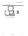
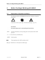
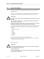
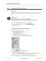
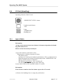
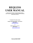
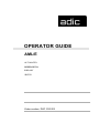
OPERATOR GUIDE
AML/E
AUTOMATED
MIXED-MEDIA
LIBRARY
/ENTRY
Order number: DOC C00 003
Table of Content
1
Data of Your AML/E System
1.1 Technical Data ...................................................................... 1-1
1.1.1 Electrical Data ............................................................. 1-1
1.2 Components ......................................................................... 1-1
1.3 Emission ............................................................................... 1-1
1.4 Layout of Your AML/E-System ............................................. 1-2
1.5 Examples of System Layouts ............................................... 1-2
1.5.1 System with 4 Hexa Towers ....................................... 1-3
1.5.2 System with 1 Quadro Tower and 2 Hexa Towers ..... 1-3
1.5.3 System with 2 Quadro Towers ................................... 1-4
2
Before You Begin Working with AML/E
2.1 Explanation of Symbols and Notes ....................................... 2-1
2.2 About This Manual ................................................................ 2-3
2.3 Product Observation ............................................................. 2-4
3
For Your Safety
3.1 Intended Use ........................................................................ 3-1
3.2 Hazard Alert Messages ........................................................ 3-2
3.3 Further Symbols ................................................................... 3-3
3.4 Area of Application ................................................................ 3-4
3.5 Intended Audience/Authorized Persons ............................... 3-4
3.5.1 Intended Audience ...................................................... 3-4
3.5.2 Authorized Personnel ................................................. 3-4
3.6 Guards .................................................................................. 3-5
3.6.1 Access to the Archive ................................................. 3-5
3.6.2 <EMERGENCY STOP> Buttons ................................ 3-6
3.6.3 Operating Modes of the AML/E System ..................... 3-8
399 DOC C00 003
Operator Guide
Page I
Table of Content
3.6.4 Guard Door of Quadro Tower .................................. 3-10
3.7 High Leakage Current ........................................................ 3-11
4
About The AML/E System
4.1 Names and Acronyms .......................................................... 4-1
4.2 Components ......................................................................... 4-1
4.2.1 AMU ............................................................................ 4-1
4.2.2 Handling Unit .............................................................. 4-2
4.2.3 Archive ........................................................................ 4-2
4.2.4 I/O Unit ....................................................................... 4-4
4.2.5 Control Cabinet .......................................................... 4-6
5
Operating The AML/E System
5.1 Operating Elements .............................................................. 5-2
5.1.1 AML/E Operating Panel ............................................. 5-2
5.2 Operating Panel of the AML/E System ................................. 5-4
5.2.1 Using the Operator Console ....................................... 5-4
5.2.2 Starting the Operating Console AMU ......................... 5-5
5.2.3 Window Layout ........................................................... 5-6
5.2.4 Selecting a Command ................................................ 5-7
5.2.5 Altering a Window´s Size ............................................ 5-7
5.2.6 Moving a Window ....................................................... 5-7
5.2.7 Closing a Window ....................................................... 5-7
5.2.8 Menus of the AMU CONSOLE ................................... 5-8
5.2.9 File Menu ................................................................... 5-9
5.2.10 Edit Menu ............................................................... 5-11
5.2.11 View Menu .............................................................. 5-12
5.2.12 Options Menu ......................................................... 5-20
5.2.13 Commands Menu ................................................... 5-21
Page II
Operator Guide
399 DOC C00 003
Table of Content
5.2.14 Service Menu .......................................................... 5-22
5.2.15 Window Menu ......................................................... 5-23
5.2.16 Help Menu .............................................................. 5-24
5.3 Starting The AML/E System (Starting "AUTO") .................. 5-25
5.4 Shutting Down the AML/E System ...................................... 5-26
5.4.1 Normal Shut-Down ................................................... 5-26
5.4.2 Shutting Down the AMU Processor .......................... 5-27
5.5 EMERGENCY STOP .......................................................... 5-28
5.5.1 Interrupting the Operation by EMERGENCY STOP . 5-28
5.5.2 Starting after an EMERGENCY STOP ..................... 5-30
5.6 I/O Unit (Handling) .............................................................. 5-31
5.6.1 Input of Media ........................................................... 5-31
5.6.2 Ejection of Media ...................................................... 5-34
6
Error Messages and Resolving Errors
6.1 General Information .............................................................. 6-1
6.2 Trouble Shooting Hints ......................................................... 6-2
6.2.1 The Equipment Cannot Be Switched on ..................... 6-2
6.2.2 The Handling Unit Has Lost a Medium ....................... 6-2
7
Appendix
7.1 Terms Used .......................................................................... 7-1
7.2 Documentation ...................................................................... 7-4
7.2.1 Bibliography AML/2 ..................................................... 7-4
7.2.2 Bibliography AML/E .................................................... 7-6
7.2.3 List of Documents AML/J ........................................... 7-8
7.2.4 List of Documents AMU Software .............................. 7-9
7.2.5 List of Documents Host Software ............................. 7-10
399 DOC C00 003
Operator Guide
Page III
Table of Content
Page IV
Operator Guide
399 DOC C00 003
Data of Your AML/E System
1
Data of Your AML/E System
1.1
Technical Data
1.1.1
Electrical Data
Europe
Power AMU
230 V ± 10 % 1, N, PE
115 ± 10 % 1, N, PE
Power entire system
230 V ± 10 % 1, N, PE
208 V ± 10 % 2, N, PE
Fusing (customer´s
site installation)
Fuse 6 A MT (type C)
Fuse 15 A MT (type C)
Voltage, power section
Frequency
1.2
North-America
310 V DC
50 Hz
60 Hz
Control voltage
= 24 V
Enclosure type
IP 50
Components
The main components are:
•
•
•
•
1.3
AML/E management unit (AMU) and operating panel
handling unit
archive
input and output area (I/O unit)
Emission
• Noise 80 dB(A)
599 DOC C00 003
Operator Guide
page 1 - 1
Data of Your AML/E System
1.4
Layout of Your AML/E-System
1.5
Examples of System Layouts
Symbol explanation:
page 1 - 2
AMU
AML management unit and operating cabinet
IO
I/O unit
HU
Handling unit
HT
Hexa tower
DC
Drive controller
D
Drive for cassette tapes
OD
Drive for optical disks
QT
Quadro tower
CC
control cabinets with control and supply components
and operating panel
MR
Maintenance room
Operator Guide
599 DOC C00 003
Data of Your AML/E System
1.5.1
System with 4 Hexa Towers
HT
HT
CC
AMU
HT
IO
HU
MR
HT
D
MR
Fig. 1-1: Layout Example with 4 Hexa Towers
1.5.2
System with 1 Quadro Tower and 2 Hexa Towers
QT
MR
HT
CC
IO
HU
MR
MR
AMU
HT
D
D
DC
MR
Fig. 1-2: Layout Example with 1 Quadro Tower and 2 Hexa Towers
599 DOC C00 003
Operator Guide
page 1 - 3
Data of Your AML/E System
1.5.3
System with 2 Quadro Towers
QT
MR
CC
IO
HU
MR
QT
MR
AMU
D
D
DC
MR
MR
Fig. 1-3: Layout Example with 2 Quadro Towers
page 1 - 4
Operator Guide
599 DOC C00 003
Before You Begin Working with AML/E
2
Before You Begin Working with AML/E
2.1
Explanation of Symbols and Notes
The following symbols and highlighted passages draw attention to important
information.
!
Explanations of these symbols (“Hazard Alert Messages” page 3/2)
Information
Information important for understanding this introduction.
<KEY>
Operating element/key on the operating panel or the keyboard of the AMU
processor
<1> + <2> Press these keys simultaneously.
“ABCD”
Switch position
$%&'
Terms appearing on the AMU operating console
( page 2-1)Reference to a description on another page
599 DOC C00 003
Operator Guide
page 2 - 1
Before You Begin Working with AML/E
If you cannot solve a problem with the aid of this document or if you are
interested in a recommendation regarding training, please contact your contract Partner or the ADIC/GRAU Technical Assistance Center (ATAC).
ADIC/GRAU Storage Systems GmbH
Eschenstrasse 3
89558 Boehmenkirch
Germany
ADIC
10949 East Peakview
avenue
Englewood, CO 80112
U.S.A.
We would be pleased to help you further.
page 2 - 2
Telefax:
+49 (0) 6196-59 08 69
Email:
[email protected]
Telephone:
1 800 827 3822
+49 6142 992364
00800 9999 3822
Operator Guide
North America
Germany
(the rest of the world)
599 DOC C00 003
Before You Begin Working with AML/E
2.2
About This Manual
This manual contains all information and instructions you need to operate the
equipment safely.
You have received comprehensive training from ADIC/GRAU Storage Systems
and can operate the AML/E system without endangering yourself or others.
WARNING!
!
Operation of the AML/E system by untrained persons can lead to dangerous
situations.
The consequence could be severe or fatal injury caused by moving parts or
contact with live connections.
Introductroy training at ADIC/GRAU Storage Systems therefore is an indispensible precondition for all who work with the AML/E system!
As an operator, you also are responsible for ensuring that only qualified personnel
authorized by ADIC/GRAU Storage Systems carries out the following on the
equipment:
•
•
•
•
•
•
•
prepare for operation
set-up
start
operate
shut down
maintain
restart
Refer to this manual when you have an operating problem.
If you cannot solve a problem call the authorized service-partner or ask ADIC/
GRAU Storage Systems for assistance.
Please note however:
WARNING!
!
Som e work and adaptations you may carry out only if you have the appropriate qualifications and training!
And most importantly:
Be sure to read Chapter 3 "For Your Safety" from page 3/1, before you begin
working with the equipment!
599 DOC C00 003
Operator Guide
page 2 - 3
Before You Begin Working with AML/E
2.3
Product Observation
We are obliged by law to monitor our products even after delivery to the customer.
Therefore please communicate every point of interest.
•
•
•
•
modified set-up data
experiences with the product
repetitive faults
difficulties with this manual
ADIC/GRAU Storage Systems GmbH
Eschenstrasse 3
89558 Boehmenkirch
Germany
page 2 - 4
Telefax:
Email:
+49 (0) 6196-59 08 69
[email protected]
Telephone:
1 800 827 3822
+49 6142 992364
00800 9999 3822
Operator Guide
ADIC
10949 East Peakview
avenue
Englewood, CO 80112
U.S.A.
North America
Germany
(the rest of the world)
599 DOC C00 003
For Your Safety
3
For Your Safety
Information
In addition to the safety instructions in this manual, local and professional
safety rules apply.
Avoid hazards when operating the equipment
• by safety-conscious behavior
• by careful action
Read and carefully observe the hazard alert information in this manual.
ATTENTION!
Knowing and observing the instruction are indispensible for operating the
AML/E system.
3.1
Intended Use
The offer and the order confirmation as well as the purposes for use defined in this
document are part of the AML/E documentation. Any use other than the specified
is not considered intended use.
This equipment is designed for processing of
• magnetic tape casettes
• optical disks
• VHS-casettes
Any other application is not considered intended use.
ADIC/GRAU Storage Systems shall not be held liable for damage arising from
unauthorized use of the system. The user assumes all risks in this aspect.
Intended use also includes
• observing the instructions supplied with the equipment (Operator and Maintenance Guides)
• observing inspection and maintenance instructions
599 DOC C00 003
Operator Guide
page 3 - 1
For Your Safety
3.2
Hazard Alert Messages
We classify the hazards in several categories. The following table shows the relation of symbols, signal words, the actual hazard, and its possible consequences.
Property
!
Damage
to...
Peopel
Symbol
Signal Word
Consequences
DANGER!
imminently
hazardous
situation
death or serious
injury (maiming)
WARNING!
potentially
hazardous
situation
possibly death or
serious injury
CAUTION!
less hazardous
situation
possibly minor or
moderate injury
potentially
damaging
situation
possibly damaging
to:
tips for users
and other
important/useful information
and notes
no hazardous or
damaging
consequences for
people or
property
ATTENTION!
Information
page 3 - 2
Definition
Operator Guide
• the product
• its environment
599 DOC C00 003
For Your Safety
3.3
Further Symbols
The table below lists all symbols used in this manual and explains their meaning.
Symbol
Damage
to ...
Signal Word
Definition
potentially
hazardous
situation
People
replaces the
pictorial
WARNING!
Hazardous
Voltage!
!
hazard of
electric shock
Consequences
possibly death or
serious injury
After an EMERGENCY STOP
and also after switching off the main
switch, voltage
can still be present
at the places marked with this symbol.
Hazard of fatal
electric shock.
!
People
CAUTION!
Laser
Radiation!
Do not stare
into beam!
possibly minor or
moderate injury
Laser radiation
Laser radiation
when opened and
interlock defeated
less hazardous
situation
possibly minor or
moderate injury
Laser radiation
Use of controls/
adjustments/performance of procedures other than
those specified
here within may
result in hazardous radiation
exposure.
identifies the
address of your
contact person
no hazardous or
damaging
consequences for
people or
property
CAUTION!
Hazardous
Radiation!
-
599 DOC C00 003
less hazardous
situation
Operator Guide
page 3 - 3
For Your Safety
3.4
Area of Application
This information applies to the entire AML/E system.
Further safety instructions for components used in the equipment are not invalidated by these instructions.
Information
Other manufacturers’ documentation forms an integral part of the AML/E
documentation.
3.5
Intended Audience/Authorized Persons
3.5.1
Intended Audience
This manual is only intended for operators of the AML/E system. Consequently,
the hazard alert messages apply only to the operation of the equipment.
ATTENTION!
Additional rules and conditions apply to service and maintenance work.
The trained specialists of the customer and the maintenance personnel of the service partner are authorized to carry out service and maintenance work.
3.5.2
Authorized Personnel
Only trained personnel of the customer (operator training) are allowed to operate
the AML/E system.
The names of trained personnel of the customer and trained specialists of the service partner (maintenance technician training) are entered into the system logbook.
The system logbook can be found in a compartment on the inside of the control
cabinet door.
page 3 - 4
Operator Guide
599 DOC C00 003
For Your Safety
3.6
Guards
The system is equipped with the following guards:
• monitored access to the archive
• <EMERGENCY STOP> button on the front of the I/O unit
• monitored guard door to the Quadro tower
3.6.1
Access to the Archive
The archive is completely enclosed in a housing. The only access to it is a monitored guard door. The interlock is active when the main switch has been switched on.
The guard door cannot be opened in operating mode “AUTO”.
The housing around the archive serves as a separating guard. It separates the danger area of the AML/E system from the normal working area.
The danger area (archive) of the AML/E-Systems is the area in which persons
could be injured due to hazardous movements of the robot the handling unit or the
storage towers.
Hazardous movements can be:
• expected movements
• unexpected movements
WARNING!
!
In the archive movements of components can cause serious injury.
Access to this area is therefore restricted to authorized persons. Persons who
have not been trained in the use of the system may only enter the archive
under supervision.
Access to the library is permitted only
• System is provided with a plug on the power supply cord (type „B“),
disconnect system with the supply plug
• after switching off the reset switch and
• securing it against being switched on again
Unauthorized persons are especially at risk in the danger area since they
• are not trained in operating the system
• are not aware of the hazards
• cannot correctly appraise the reactions of the system
599 DOC C00 003
Operator Guide
page 3 - 5
For Your Safety
3.6.2
<EMERGENCY STOP> Buttons
Information
The yellow luminous push-button <CONTROL OFF> on the operating panel
has the same function as the <EMERGENCY STOP> button.
All <EMERGENCY STOP> buttons (I/O unit …) have the same function: EMERGENCY STOP switches off the output electronics. All movements of the handling
unit and the storage towers stop immediately.
When persons or property are at risk immediately press the nearest <EMERGENCY STOP> button.
Moving parts stop at once.
WARNING!
Hazardous Voltage!
Pressing an <EMERGENCY STOP> button will not render the entire
AML/E system voltageless. Only the drive amplifiers are switched off.
Emergency stop does not switch off:
•
•
•
•
the control units of the handling unit and the storage towers
the AMU processor
the drives
the compressed air supply
Cut the power supply to these components at a suitable point (e. g. connecting plug
or switch)!
page 3 - 6
Operator Guide
599 DOC C00 003
For Your Safety
ATTENTION!
If the <EMERGENCY STOP> buttons are frequently used contrary to their
purpose, just to stop the system, this may lead to:
• increased wear of mechanical parts
• damage to electronic and electric components of the AML/E system
Do not use the <EMERGENCY STOP> buttons to stop the normal operation
of the AML/E system.
Stop the system only with the appropriate AMU or host computer commands
( HACC/ROBAR)!
ADIC/GRAU Storage Systems will not be responsible for damages caused by
improper use of the <EMERGENCY STOP> buttons. The risk lies entirely with
the user.
WARNING!
!
Movement of components inside the archive can cause serious injury.
Before releasing the <EMERGENCY STOP> buttons and before starting the
AML/E system, ensure that the start will not endanger persons or property!
599 DOC C00 003
Operator Guide
page 3 - 7
For Your Safety
3.6.3
Operating Modes of the AML/E System
Operating mode "AUTO"
In the "AUTO" mode the host computer controls the AML/E system.
WARNING!
!
Movements of components in the archive can cause serious injury.
In "AUTO" mode nobody must be inside the archive.
Before starting "AUTO" operation ensure nobody is in the archive.
The archive access interlock is active when the main switch is on. The guards are
activated when the luminous push-button <CONTROL ON> is pressed.
page 3 - 8
Operator Guide
599 DOC C00 003
For Your Safety
Operating mode “EMERGENCY”
“EMERGENCY” operation is intended for
• manual input and output of media
• manual operation of drives
• manual movement of storage towers
In this operating mode only personnel entered in the system logbook (trained personnel and specialists) may work inside the archive.
WARNING!
!
In this operating mode the door lock of the archive is not active.
a) Lock the main switch in position “OFF”
b) Carefully guard the key or keep it with you always.
The handling unit is shut down.
The Quadro tower interlocks are inactive.
599 DOC C00 003
Operator Guide
page 3 - 9
For Your Safety
3.6.4
Guard Door of Quadro Tower
In the “AUTO” operating mode the guard door of the Quadro tower
• must be open (AML/2-System).
• must be closed (AML/E-System).
The guard door is locked when the Quadro tower moves.
In the AML/E system it can be opened only in “EMERGENCY” operating mode.
Information for AML/2 twin systems
If both robots are to run in the “AUTO” operating mode the guard doors on
both sides must be open.
If one robot is to run in “AUTO” and the other in “MANUAL” the guard
doors on the side with the robot running in “MANUAL” must be closed.
Fig. 3-1: Quadro Tower Guard Door
page 3 - 10
Operator Guide
599 DOC C00 003
For Your Safety
3.7
High Leakage Current
WARNING
High Leakage Current
Earth connection essential before connecting supply.
599 DOC C00 003
Operator Guide
page 3 - 11
For Your Safety
page 3 - 12
Operator Guide
599 DOC C00 003
About The AML/E System
4
About The AML/E System
4.1
Names and Acronyms
For same components will be used different names in Europe and North America
Acronym
Europe
AML/E
AML/E
Description
Automated
Mixed-Media
Library
/Entry
AMU
AML Management Unit
(Archive Management Unit)
AMS
AML Management Software
(Archive Management Software)
DAS
Distributed AML Server
HACC
I/E/F
4.2
Acronym
North America
HCC
Host AML Communication Control
I/O Unit
(Unit for Insert, Eject, Forein Media)
Components
The main components of the AML/E system are:
•
•
•
•
•
4.2.1
AML Management Unit (AMU) and operating panel
handling unit
archive
I/O unit
control cabinet with control and power supply components
AMU
The AMU is the central interface of the AML/E library. During normal operation,
the host computer controls the system. The AMU consists of hardware and soft-
599 DOC C00 003
Operator Guide
page 4 - 1
About The AML/E System
ware components.
Hardware Component
AMU hardware consists of:
• a computer with a color monitor, a mouse, a keyboard
• a network adapter (Token Ring, Ethernet, or FDDI adapter)
Software Component
The AMU software components are:
•
•
•
•
OS/2 Operating System
Communication Manager/2, TCP/IP
Database Manager/2
AMU Archive Management Software (AMS)
In normal (Automatic) operating mode, the host computer directs the AML/E
library and the AMU software operates transparently. Usually, commands are only
input at the AMU console when specific operator intervention is required.
4.2.2
Handling Unit
The handling unit acoomplishes the mechanical access to the physical archive and
the drives.
It executes the commands of the AMU and sends a feedback signal to it.
Functions
• identifies media by reading the barcode
• carries out the handling commands (e.g. Mount, Keep …)
Components of the handling unit
• commissioning robot
• gripper with laser scanner (barcode scanner)
4.2.3
Archive
The archive is divided into compartments.
page 4 - 2
Operator Guide
599 DOC C00 003
About The AML/E System
Logical coordinates define the position of each compartment in the archive.
Each medium in the system is identified by a barcode label with volser. The assignment of this number to its logical coordinates is stored in the archive catalog.
599 DOC C00 003
Operator Guide
page 4 - 3
About The AML/E System
4.2.4
I/O Unit
The I/O unit inputs and outputs the media.
Diagram of the components:
Problem
Box
HandlingBox 1
Section
1 and 2
HandlingBox 2
I/O-Unit
60/120 B
Section
3 and 4
HandlingBox 3
(on 120)
HandlingBox 4
Fig. 4-1: Diagram of the I/O Unit
page 4 - 4
Operator Guide
599 DOC C00 003
About The AML/E System
Overview of the I/O unit B:
Archive access
Problem box. It contains:
• unidentified media
• media in case of a robot failure
Terminal board
Controls
Handling box
Compressed air
supply
Fig. 4-2: View of the I/O Unit
599 DOC C00 003
Operator Guide
page 4 - 5
About The AML/E System
4.2.5
Control Cabinet
Components
•
•
•
•
•
•
•
page 4 - 6
drive amplifier and power supply unit 160
rho control unit (Bosch IQ 140 M)
supply voltage module
Interface modem
frequency converter for Hexa tower
connector panel
operating panel
Operator Guide
599 DOC C00 003
Operating The AML/E System
5
Operating The AML/E System
In "AUTO" operation the host computer controls the AML/E system.
The operator only
• adds or
• removes
media from the archive and
• mounts
• removes
non-system media.
Commands are entered via the host computer console.
All AMU commands of the service menu are to be used only by service personnel
and are password protected.
When the system fails the operator can process media in the "EMERGENCY" operating mode.
Procedure for hand operation:
a)
b)
c)
d)
e)
f)
g)
h)
599 DOC C00 003
switch off the equipment and secure it against switch on
enter the archive
secure axes 1 + 2 of the handling unit with the bracket from sliding down
position the handling unit manually so you can easily reach the media and
the drives
remove the crank of the archive access door
using the crank, rotate the storage tower into position
remove the medium
mount the medium in the drive
Operator Guide
page 5 - 1
Operating The AML/E System
2
Luminous push-button (green)
<CONTROL ON>
The light inside the push-button
lights up when pressed.
Activates the control unit and drive
amplifiiers of the handling unit and
the storage towers.
Preconditions:
• main switch is on
• <CONTROL OFF> lights up
3
Luminous push-button (yellow)
<CONTROL OFF>
The lihgt inside the push-button
lights up when control unit is ready
to operate after the main switch has
been switched on.
Deactivates the controller of the
• handling unit
• storage towers
4
599 DOC C00 003
Push-button
<SYSTEM LIGHTING>
Operator Guide
Switches the lighting of the danger
area on and off.
page 5 - 3
Operating The AML/E System
5.2
Operating Panel of the AML/E System
Instructions input via the operating panel of the AML/E system (AMU operating
panel) have the same priority as host instructions.
Input at the AMU must be restricted to the following situations:
• start and stop of the AMU
Information
All non-executable commands or options are displayed with a shadow.
5.2.1
Using the Operator Console
Layout and operation conform to SAA standards.
It is controlled by
• the keyboard
• the mouse
Further information is found in the OS/2 manuals.
page 5 - 4
Operator Guide
599 DOC C00 003
Operating The AML/E System
5.2.2
Starting the Operating Console AMU
Information
Do this only when the operating console AMU is not shown on the monitor or
has been quit unintentionally.
a) Press <CTRL> + <ESC> (process list).
b) Check whether AMU and KRN have already been started.
c) If both processes have been started change to the AMU (select the process and
confirm by pressing <ENTER>).
d) If one of the two processes has not yet been started perform a system shut-down
(page 5/27) and then press <Ctrl> + <Alt> + <Del>.
599 DOC C00 003
Operator Guide
page 5 - 5
Operating The AML/E System
5.2.3
Window Layout
System menu field Title bar
Corner
Menu bar
Symbol field
Max. size field
Frame
Fig. 5-2: Operating Console: Window Layout
Information
When the window is active the title bar has a green background. When the
window is inactive the title bar has a grey background.
The following functions are the same in all windows:
Button
Function
Cancels the current function and closes the window.
Opens the online help.
page 5 - 6
Operator Guide
599 DOC C00 003
Operating The AML/E System
5.2.4
Selecting a Command
With the mouse:
a) move the mouse pointer to the desired menu in the menu bar.
b) click on the menu; the menu opens.
c) click on the command in the menu; the command window opens.
With the keyboard:
a) press the <ALT> key and the underlined letter in the menu bar. The menu opens.
b) Now press the underlined letter in the menu to select the command.
With a command code:
a) If a key or a combination of keys is specified following the command you can
directly select the command with it.
5.2.5
Altering a Window´s Size
Resizable windows have a frame all around (e. g. Trace window).
a) Move the mouse to any corner of the active window.
The mouse pointer changes into a double arrow.
b) Press the mouse button and pull the window to the desired size while you keep
the mouse button pressed.
5.2.6
Moving a Window
a) Move the mouse pointer onto the title bar.
b) Move the window while you keep the mouse button pressed.
5.2.7
Closing a Window
Closed the window by a double click on the system menu field.
599 DOC C00 003
Operator Guide
page 5 - 7
Operating The AML/E System
5.2.8
Menus of the AMU CONSOLE
Commands of the operating console not shown with a shadow are explained
below:
Fig. 5-3: Menu Overview
page 5 - 8
Operator Guide
599 DOC C00 003
Operating The AML/E System
5.2.9
File Menu
Fig. 5-4: File Menu
Command
3ULQW
Field
Explanation
Print selected lines from the log data.
Information
First select the lines to be printed in the LOG
Control Center.
«WRILOH
Store as a text file.
Fig. 5-5: Window: Print to File
Enter the target file name with path
(e.g. c:\text\logascii.txt).
6WDUWSULQW
599 DOC C00 003
starts the filing.
«QRUPDO
Print with standard font
«JUDILF
Print with graphic front
Operator Guide
page 5 - 9
Operating The AML/E System
Command
6KXWGRZQ
Field
Explanation
Prepares shut-down of the AML/E system.
$0/
Fig. 5-6: Window: Shutdown of AML
ATTENTION!
Before switching off interrupt the communication with the host computer (e.g. with HOLD
1,1).
<HV
The current command will still be processed.
After that, all modules of the AMU will stop
and the database will be closed.
The handling unit moves to its initial position. Preparation for shut-down of the AML/
E system.
Information
Shutting down off the system
(page 5/26)
1R
page 5 - 10
Return to the programme, no shut-down.
Operator Guide
599 DOC C00 003
Operating The AML/E System
5.2.10
Edit Menu
Fig. 5-7: Edit Menu
Command
599 DOC C00 003
Explanation
&XW
Cut the marked object and file it in the intermediate memory
(computer memory).
&RS\
Copy the marked object to the intermediate memory.
3DVWH
Insert the object from the intermediate memory at the current
cursor position.
Operator Guide
page 5 - 11
Operating The AML/E System
5.2.11
View Menu
Fig. 5-8: View Menu
Calls up information in various windows.
Command
$UFKLYH
Field
Explanation
Checking and changing of entries for specific compartments in
the archive catalog.
After input of information (e.g. volser) the respective archive
catalog entry is displayed.
Fig. 5-9: Window: Archive Catalog Management
page 5 - 12
Operator Guide
599 DOC C00 003
Operating The AML/E System
Command
$UFKLYH
Field
Explanation
&2ZQHU
Medium owner: indicates the robot or robots
which can access this medium.
$WWULEXWH
Status of the medium:
(continued)
• Occupied: compartment occupied
• Ejected: medium has been ejected
• Initial: initial attribute condition
(initialized, available)
• Undefined: not defined
• Empty: campartment empty
• Mounted: medium mounted in drive
• Temp Away: attribute not occupied
(no home position)
• Temp Here: attribute not occupied
(dynamic intermediate storage - problem
box)
Type of compartment
7\SH
•
•
•
•
•
•
Storage: archive compartment
Insert: insertion compartment
Eject: ejection compartment
Foreign: foreign medium compartment
Clean: cleaning medium compartment
Dynamic: archive compartment for volser
ranges not hierarchically defined
• Problem: compartment in the problem
box (I/O unit)
599 DOC C00 003
8VH&RXQW
Number of times compartment is accessed.
&UDVK&RXQW
Number of times compartment is accessed
without success. Counts the number of times
the crash sensor on the gripper is activated.
9ROVHU
Cartridge number
Operator Guide
page 5 - 13
Operating The AML/E System
Command
$UFKLYH
Field
Explanation
9LHZ9ROVHU
Displays the archive catalog entry for the
volser entered.
9LHZ
Displays the archive catalog entry for the
logic archive coordinate entered.
(continued)
&RRUGLQDWH
Information
8SGDWH
&RRUGLQDWH
This command can requires
logging in.
Updates the archive catalog entry for the
archive coordinate.
ATTENTION!
The existing entry in the
archive catalog will be overwritten.
Wrong entries can lead to discrepancies in the archive.
&RRUGLQDWH
Logical coordinate of the medium in the
archive. The digits of the coordinates indicate the following:
• 1, 2: Device type (list see Maintenance
Guide)
• 3, 4: Device number
• 5, 6: Segment number
• 7, 8: Row number
• 9, 10: Compartment number
&RPELQHG
Generates a "Continuous Send" command.
&RPPDQGV
&RPELQH2QO\
212))
The command string is combined but
not executed.
21
The command string is combined and
executed.
2))
page 5 - 14
Operator Guide
599 DOC C00 003
Operating The AML/E System
Command
7UDFH
Field
Explanation
Online or off-line record of the internal operations of the
AMU-Software. The records can be selected by levels (AMU
processes). A list of the trace levels is found in the Maintenance Guide.
Trace levels can be selected with the <SPACE> bar or the
mouse.
Information
The selection of trace can slow down the processing speed!
Change the selection only after consulting
ADIC/GRAU Storage Systems.
Standard selection: no traces
ATTENTION!
The memory for the current trace is limited.
When failures occur file the trace as soon as
possible.
Online Trace:
Displays the current trace on the monitor.
Fig. 5-10: Window: Trace Online
599 DOC C00 003
Operator Guide
page 5 - 15
Operating The AML/E System
Command
7UDFH
(continued)
Field
Explanation
Offline Trace:
Saves the current trace in a file.
Fig. 5-11: Window: Trace Offline
)LOH
Files the recorded trace.
After formatting it, this file can be printed
( )RUPDW).
)RUPDW
Formats a file saved with the )LOH-command
for printing.
Fig. 5-12: Window: Format Trace Files
,QILOH
: source file name with path
: target file name with path
(e. g. a:\name or c:\amu\logs-trc\name).
2XWILOH
starts the formatting.
The execution will be confirmed by display
of the message “IRUPDWWHG“.
6WDUW)RUPDWWLQJ
page 5 - 16
Operator Guide
599 DOC C00 003
Operating The AML/E System
Command
/RJ
Field
Explanation
The LOG control center records all messages, e.g.
•
•
•
•
host computer commands
messages to the host computer
operator interventions
error messages
Log files begin daily at 0.00 hours. If disk space available
drops below 10MB, the oldest log file will be deleted.
Information
Log files cannot cover several days!
There is only one log file for each day.
The LOG control center has two modes of operation
Online (display of the current log)
Fig. 5-13: LOG Control Center Window - Online
SearchMode (display of stored logs)
Fig. 5-14: LOG Control Center Window - SearchMode
599 DOC C00 003
Operator Guide
page 5 - 17
Operating The AML/E System
Command
/RJ«
(continued)
Field
Explanation
In the 6HDUFK0RGH select a time period (begin/end).
The log strings recorded during this period will appear in the
window.
Information
Press <VWDUW> after each change in the
6HDUFK0RGH . This activates the new settings.
Precondition: 6HDUFK0RGH
7LPH
6SHFLILFDWLRQ
6WDUW: Default is the current date. You may
change the date. Adjust the time from which
to start displaying the log strings.
: The date specified in VWDUW is the
default and cannot be changed. Set the time
for the end of the log string display.
(QG
5HDGILOH
Precondition: 6HDUFK0RGH
Select a log file. Proceed as described for
7LPH6SHFLILFDWLRQ. The date is contained
in the name.
Log file name convention::
• identification: ORJ
• date with zeros: e.g. • count number: e.g. 6HDUFKVWULQJ
Precondition: 6HDUFK0RGH
Search function: Enter the text string (character sequence). The log file selected will
be searched for that string. The strings found
will be shown marked in the list box. Exception: If 0DWFKHV2QO\ is selected only the
string found appears in the list box.
page 5 - 18
Operator Guide
599 DOC C00 003
Operating The AML/E System
Command
/RJ«
Field
'LVSOD\
Explanation
'DWH
(continued)
: The log string is preceded by the date.
: The log string is preceded by the
corresponding sequence number (internal
log number).
6HT1R
0DWFKHV2QO\: Displays the log strings specified in 0VJ/HYHO and 7LPH6SHFLILFD
WLRQ .
0VJ/HYHO
Precondition: 6HDUFK0RGH
•
: displays only log strings with
error messages
• ,QIR: displays only log strings with information
Up-dates the LOG Control Center with the
new settings.
6WDUW
2QOLQH
or
6HDUFK0RGH
8QVHOHFWDOO
$OORZVHO
HFWLRQV
599 DOC C00 003
(UURUV
Switches over between the two modes
•
•
(current logs)
6HDUFK0RGH (stored logs)
2QOLQH
Deletes all marks in the list box.
Enables the selection of log strings for printing or filing.
Operator Guide
page 5 - 19
Operating The AML/E System
5.2.12
Options Menu
Fig. 5-15: Options Menu
Command
6LPXODWLRQ
Field
Explanation
ATTENTION!
RQO\
Executed commands alter the archive catalog
although no medium is actually moved.
Switch for simulation mode: No processing of commands outside the AMU. The AMU processes the commands as far as
possible and confirms their execution to the host (positive acknowledgement).
page 5 - 20
Operator Guide
599 DOC C00 003
Operating The AML/E System
5.2.13
Commands Menu
Fig. 5-16: Commands Menu
Information
All commands in this menu
• are provided exclusively for service personnel and are protected by a
password.
• open the command window
599 DOC C00 003
Operator Guide
page 5 - 21
Operating The AML/E System
5.2.14
Service Menu
Fig. 5-17: Service Menu
Information
All commands in this menu (except /RJRQ) are provided exclusively for
service personnel and are protected by a password
Command
/RJRQ
Explanation
Logging in of service personnel with password.
Fig. 5-18: Window: Logon AMU Service
page 5 - 22
Operator Guide
599 DOC C00 003
Operating The AML/E System
5.2.15
Window Menu
Fig. 5-19: Window Menu
Command
Explanation
&ORVHDOO
Closes all open windows.
:LQGRZV
Calls up the respective window.
(List of all
open windows)
599 DOC C00 003
Operator Guide
page 5 - 23
Operating The AML/E System
5.2.16
Help Menu
Fig. 5-20: Help Menu
Command
Explanation
+HOSIRUKHOS
Information about the help function.
([WHQGHG
Extended help
KHOS
Fig. 5-21: Window: Help for AMU
page 5 - 24
.H\VKHOS
Key assignment
+HOSLQGH[
Help index
$ERXW
Displays copyright information and AMU version number.
Operator Guide
599 DOC C00 003
Operating The AML/E System
5.3
Starting The AML/E System (Starting "AUTO")
In the "AUTO" mode the host computer controls the system.
WARNING!
Movements of the system components inside the archive can cause severe
injuries.
Before closing the access door and before starting the AML/E system ensure
that nobody is inside the archive.
ATTENTION!
The handling unit needs sufficient vacant space for its reference movement.
During the reference movement all axes of the handling unit and the Quadro
towers move. Objects and system components within the reach of the handling unit can be damaged.
a) Check
- <EMERGENCY STOP> buttons released
- all handling boxes inserted into the I/O unit
- I/O door closed and locked
- archive access door closed and locked
b) Switch on the main switch.
Wait until <CONTROL OFF> lights up yellow.
c) Switch on the AMU processor (after booting OS/2 starts all AMU processes).
Wait until the operator console (AMU window) has been started.
d) Open the LOG Control Center window (select /RJ« in the 9LHZ menu and
check the follwing messages
- The module Kernel is started
- The module Database is started
e) Press <CONTROL ON>
<CONTROL OFF> switches off, <CONTROL ON> lights up green.
All control units of the AML/E system are ready to operate.
f) Wait for the following messages in the LOG Control Center window
- STATUS: robot ready 700
- STATUS: tower “x” ready 800 (“x” = Number of the storage tower)
- STATUS: E/I/F ready 900
599 DOC C00 003
Operator Guide
page 5 - 25
Operating The AML/E System
Information
The message “E/I/F closed” may mean
• the I/O unit door is not closed and locked
• not all handling boxes have been inserted
The starting of the AML/E system from the host computer is described in a separate start/stop procedure tailored to the particular AML/E system (Operating
Manual AML/E ROBAR/BS2000 HACC/MVS).
5.4
Shutting Down the AML/E System
ATTENTION!
This section describes the normal shutdown procedure and deviations are
allowed only in case of emergency. An emergency shutdown can alter or
destroy files that are required to restart the system.
Stopping the AML/E system from the host computer is described in a separate
start/stop procedure tailored to the particular AML/E system ( Operating Manual
AML/E ROBAR/BS2000 HACC/MVS).
5.4.1
Normal Shut-Down
Shut the system down only from the operator console.
•
•
a)
b)
Stopping of individual units is not possible.
A partial stop is only a logical condition for the AMU
End AMU operation with the command "SKXWGRZQ$0/…".
Press <CONTROL OFF>.
<CONTROL ON> switches off
ATTENTION!
Never switch off the main switch before you have pressed <CONTROL OFF>
Parts of the control unit could be damaged!
c) Switch off the main switch.
page 5 - 26
Operator Guide
599 DOC C00 003
Operating The AML/E System
5.4.2
Shutting Down the AMU Processor
Information
The processor runs continuously and is therefore not in the main switch circuit.
ATTENTION!
Possible data loss or very long start-up procedure.
Switch the AMU processor of only in the manner described below.
Before switching off the AMU processor:
• shut down the AMU operator console ( 6KXWGRZQ$0/«)
• shut down the system
Shutting down the system OS/2 Version 2.1
a) change to the OS/2 desktop
- open the task list with <CTRL> + <ESC>
- select “Desktop Icon - View”
b) call up the system menu
- if an icon is selected press <SPACE>
- Press <SHIFT> + <F10> or the right mouse button
Fig. 5-22: System Menu OS/2
c) select 6KXWGRZQ« (system shut-down)
d) confirm the subsequent querries
e) wait for the message “Shutdown has completed. It is now safe to turn off your
computer, or restart the system by pressing Ctrl+Alt+Del”
f) do not switch off the processor before the above message appears
599 DOC C00 003
Operator Guide
page 5 - 27
Operating The AML/E System
5.5
EMERGENCY STOP
5.5.1
Interrupting the Operation by EMERGENCY STOP
Information
The yellow luminous push-button <CONTROL OFF> on the operating panel
has the same function as the <EMERGENCY STOP> pusb-buttons.
All <EMERGENCY STOP> push-buttons (I/O unit...) have the same function. An
EMERGENCY STOP switches off the power electronics. All movements of the
handling unit and the storage towers are stopped immediately.
When persons or property are endangered immediately press the nearest <EMERGENCY STOP> push-button.
The moving parts will stop immediately.
• Power supply to the drive amplifiers is shut off.
• <CONTROL ON> switches off
• <CONTROL OFF> lights up
WARNING!
Dangerous voltages!
Pressing an <EMERGENCY STOP> button will not render the entire
AML/E system voltageless. Only the drive amplifiers are switched off.
Emergency stop does not switch off:
•
•
•
•
the control units of the handling unit and the storage towers
the AMU processor
the drives
the compressed air supply
Cut the power supply to these components at a suitable point (e. g. connecting plug
or switch)!
page 5 - 28
Operator Guide
599 DOC C00 003
Operating The AML/E System
ATTENTION!
If the <EMERGENCY STOP> buttons are frequently used contrary to their
purpose, just to stop the system, this may lead to:
• increased wear of mechanical parts
• damage to electronic and electric components of the AML/E system
Do not use the <EMERGENCY STOP> buttons to stop the normal operation
of the AML/E system.
Stop the system only with the appropriate AMU or host computer commands
( HACC/ROBAR)!
599 DOC C00 003
Operator Guide
page 5 - 29
Operating The AML/E System
5.5.2
Starting after an EMERGENCY STOP
WARNING!
Movements of system components in the archive can cause severy injury.
Before releasing an <EMERGENCY STOP> push-button and before re-starting the AML/E system ensure that persons or property are not endangered!
a) Eliminate the cause of the EMERGENCY STOP.
b) Release the <EMERGENCY STOP> push-button (turn it left).
ATTENTION!
Upon the start of the system the handling unit automatically carries out a
reference movement. During the reference movement all axes of the handling
unit and the storage towers move.
Objects and system components within the reach of the axes can be damaged.
c) Start the system
(“Starting The AML/E System (Starting "AUTO")” page 5/25).
page 5 - 30
Operator Guide
599 DOC C00 003
Operating The AML/E System
5.6
I/O Unit (Handling)
Operating elements of the I/O unit
<EMERGENCY STOP> button
Luminous push-button
<ON>
Lamp
<OPERATION>
Handling box
5.6.1
Input of Media
Information
As long as the operator intervenes (shutter in bottom end position) the handling unit cannot access.
Release of the I/O unit may be delayed.
a) Press the luminous push-button <ON> .
This generates a request to open the I/O door.
- The shutter closes.
As long as it is moving, the luminous push-button <ON> is continuously lit.
- When the shutter has reached its bottom end position <OPERATION> will
light up and the I/O door is unlocked.
- The luminous push-button <ON> switches off.
- The message ,2FORVHG appears in the AMU log.
b) Open the I/O door as far as possible within 15 seconds.
Information
If the I/O door remains closed the shutter opens after 15 seconds.
c) Remove the handling boxes or empty the problem box.
599 DOC C00 003
Operator Guide
page 5 - 31
Operating The AML/E System
d) Load the handling boxes removed or the problem box. Begin left in the bottom
row (opening of the box facing you).
The I/O unit is divided in input, output and foreign areas:
- MVS, HACPARM1 in the LDEV commands,
- all other operating systems: archive catalogue (type of archive coordinate)
e) Put the loaded handling boxes back into the I/O unit.
f) Close the I/O door.
- The door retaining mechanism must audibly latch into place.
- The <OPERATOR> lamp will blink if not all boxes are inserted correctly.
- The shutter opens automatically.
- The <OPERATOR> lamp and the luminous push-button <ON> switch off.
Information
Therefore remove only handling boxes you want to load.
Information
If cartridge storage compartments are defined as Eject in the configuration
the AMU, through ROBAR, carries out an automatic inventory of these compartments after manual access.
System media
System media have a Volser.
The handling unit identifies the medium by its barcode label and reports the volser
to the AMU.
Foreign (non-system) media
Non-system media do not have volsers readable for the AML/E system.
• They are not identified by a barcode label.
• They are not accepted into the archive.
Non-system media are always located in compartments reserved for non-system
media in the handling boxes. They are processed directly from these compartments.
ATTENTION!
The compartment number and the input at the AMU must be identical.
page 5 - 32
Operator Guide
599 DOC C00 003
Operating The AML/E System
Be sure to place the media in the right compartments of the handling box.
Non-system media receive a symbolic volser. Symbolic volsers begin with an "*"
and are registered in the AMU archive catalog. The symbolic volser for the first
compartment thus is "*FR001".
Cleaning cassettes for BS2000/ROBAR
Cleaning cassettes do not need a barcode label. They are stored in defined compartments of the archive.
Cleaning cassettes must be stored in the archive for each drive. After a predefined
number of cleaning cycles (e. g. 500) the host computer automatically sends a
command to eject them ( documentation of interface software).
Cleaning cassettes receive a symbolic volser in the archive catalog.
The symbolic volser is “*CL....”. It can be attached to the cassette on a barcode
label. This will simplify the replacement of cleaning cassettes. A cleaning cassette
can then be stored with the ROBAR command “IN *CL…” .
Cleaning cassettes for MVS/VM/VSE users
The cleaning cassettes do not have a barcode label.
Cleaning cassettes must be stored in the archive for each drive. After a predefined
number of cleaning cycles (e. g. 500) the host computer automatically sends a
command to eject them ( documentation of interface software).
ATTENTION!
When you replace a cleaning cassette put the barcode label of the old cassette
onto the new cassette!
Otherwise the system will not recognize the cassette as a cleaning cassette.
Fast input
In a first input cycle only the defined fast input compartments are querried.
599 DOC C00 003
Operator Guide
page 5 - 33
Operating The AML/E System
5.6.2
Ejection of Media
The ejection command is send by the host computer. The handling unit places the
media in the handling boxes in the I/O unit.
When the host controlled ejection is complete you can remove the media or the
handling boxes.
The further operating procedure is identical with insertion (page 5/31).
page 5 - 34
Operator Guide
599 DOC C00 003
Error Messages and Resolving Errors
6
Error Messages and Resolving Errors
6.1
General Information
All messages including error messages are displayed in the Log window of the
AMU operator console . The error number is indicated in brackets at the end of the
error message.
Additionally the host computer receives an error information.
With the error number additional information can be called up on the operating
system level (e.g. in an OS/2 window).
Enter "help amu" followed by the error number to call up the information.
A list of error messages is contained in the Maintenance Guide.
If no action is recommended or if the error cannot be resolved call the maintenance
technician of your service-partner or ADIC/GRAU Storage Systems.
CAUTION!
If you must enter the danger area inside the archive housing to determined or
resolve an error, be sure to observe the safety instructions .
599 DOC C00 003
Operator Guide
page 6 - 1
Error Messages and Resolving Errors
6.2
Trouble Shooting Hints
6.2.1
The Equipment Cannot Be Switched on
Check the following:
• Is voltage present? (fan noise in the control cabinet?)
• Are all EMERGENCY STOP components deactivated?
- Are the <EMERGENCY STOP> push-buttons released?
- Quadro tower door(s) closed?
- I/O door closed?
- Access to the archive closed?
• Is the yellow <CONTROL OFF> push button lit?
- If it is not switch the main switch off.
- After approx. 2 minutes switch it on again .
- If the system still cannot be switched on call the maintanance technician of
your service partner.
6.2.2
The Handling Unit Has Lost a Medium
a)
b)
c)
d)
e)
f)
g)
h)
page 6 - 2
Stop the equipment.
Move the handling unit to its initial position.
Switch the control unit off.
Switch off the main switch and secure against switching on.
You can now enter the archive to pick up the medium.
Put the medium into the I/O unit.
Leave the archive and lock the access door.
Switch the system on again .
Operator Guide
599 DOC C00 003
Appendix
7
Appendix
7.1
Terms Used
AML/E
Automatic cassette tape operating archive; AML/E
software and physical archive.
/E means Entry
AML operating panel
Operating panel on the control cabinet for switchon/off and monitoring of the AML/E system.
AMU
AML Management Unit
Central intelligence of the AML/E system.
Consists of hard and software.
AMU operator console
OS/2 programme for operation of the AML/E
system.
Archive
The archive consists of:
• physical archive and
• logical archive.
The physical archive consists of storage towers for
cassette tapes and optical disks (= media). The logical archive (archive catalog) is the list of volsers
assigned to the compartments in the physical
archive.
599 DOC C00 003
Archive catalog
An OS/2 database with the logical archive.
Contains the assignment of volsers to to the compartments in the physical archive as well as further
vital information about the media and the drives.
Archive coordinates
These define the compartment of a medium in the
physical archive.
Barcode label
Label on the medium, contains the volser in a form
readable for the robot (barcode).
Click
Short pressing and releasing of the mouse button.
Operator Guide
page 7 - 1
Appendix
Command, instruction
A command sent to the AML/E system:
• from the host computer
• direct operator input at the
AMU operator console
Configuration
Determins the structure of the AML/E system. The
configuration specifies the components and their
connections.
Foreign medium
Cartridges not listed with a Volser in the archive
catalog. They are processed by the AML/E system
via the I/O unit.
Handling box
Storage box for media in the I/O unit.
Handling unit
Robot with 3 axes.
Hexa tower
Storage archive with 6 Segments for 720, 900 or
1080 media.
Host computer
Large computer system.
The data of the host computer is stored in the AML/
E system (archive) on media.
•
•
•
•
•
•
•
•
page 7 - 2
host computer
AMUs
rhos
storage towers
linear shelves
handling unit
specials
drives
I/O unit
Input/output area. Media are inserted and ejected
via the I/O unit.
ent in the archive.
Linear shelf
Storage archive (only one storage level)
Medium
Storage medium in the archive, e. g. a magnetic
tape cassette or optical disk
Operator
Trained operator of the AML/E system.
Quadro tower
Storage archive with 32 segments.
Section
Compartment of a handling box in the I/O unit.
Segment
A column of rows in a storage tower.
Operator Guide
599 DOC C00 003
Appendix
599 DOC C00 003
System media
System media have a volser, are stored and registered in the archive.
Volser, VSN
english: volume serial number
An up to six digit alphanumeric designation. It
identifies one medium (cassette, optical disk) in the
archive.
The volser is attached to the rear of the medium on
a barcode label and can be read by the robot.
Operator Guide
page 7 - 3
Appendix
page 7 - 4
Operator Guide
599 DOC C00 003
Index
A
AML/2
term . . . . . . . . . . . . . . . . . . . . . 7-1
About . . . . . . . . . . . . . . . . . 5-24, 5-25
access to the archive . . . . . . . . . . . . 3-5
address . . . . . . . . . . . . . . . . . . . . . . 2-2
Allow selections (Log…) . . . . . . . 5-19
AML/2
operating panel (term) . . . . . . . 7-1
AMU
copyright/version . . . . . 5-24, 5-25
error messages . . . . . . . . . . . . . 6-1
location in the system . . . 1-1, 4-1
operator console . . . . . . . . . . . . 5-4
operator console (term) . . . . . . 7-1
starting . . . . . . . . . . . . . . . . . . . 5-5
term . . . . . . . . . . . . . . . . . . . . . 7-1
archive
AMU command . . . . . . . . . . . 5-12
catalog (term) . . . . . . . . . . . . . . 7-1
coordinates (term) . . . . . . . . . . 7-1
function . . . . . . . . . . . . . . . . . . 4-2
location in the system . . . 1-1, 4-1
term . . . . . . . . . . . . . . . . . . . . . 7-1
Attribute . . . . . . . . . . . . . . . . . . . . 5-13
authorized personnel . . . . . . . 2-3, 3-4
AUTO
operating mode . . . . . . . . . . . . 3-8
starting . . . . . . . . . . . . . . . . . . 5-25
B
barcode label . . . . . . . . . . . . . . . . . 7-1
C
click . . . . . . . . . . . . . . . . . . . . . . . . . 7-1
Close all . . . . . . . . . . . . . . . . . . . . . 5-23
Combine only (OFF) . . . . . . . . . . . 5-14
Combined command . . . . . . . . . . . 5-14
command
selecting . . . . . . . . . . . . . . . . . . 5-7
term . . . . . . . . . . . . . . . . . . . . . . 7-2
command code . . . . . . . . . . . . . . . . 5-7
commands menu . . . . . . . . . . . . . . 5-21
compressed air supply . . . . . . . . . . . 4-5
configuration (term) . . . . . . . . . . . . 7-2
connection
electrical . . . . . . . . . . . . . . . . . . 1-1
control cabinet . . . . . . . . . . . . . . . . . 4-6
AMU . . . . . . . . . . . . . . . . . . . . . 4-1
CONTROL OFF . . . . . . . . . . . . . . . 5-3
CONTROL ON . . . . . . . . . . . . . . . . 5-3
Coordinate . . . . . . . . . . . . . . . . . . . 5-14
Copy . . . . . . . . . . . . . . . . . . . . . . . 5-11
C-Owner . . . . . . . . . . . . . . . . . . . . 5-13
Crash Count . . . . . . . . . . . . . . . . . . 5-13
Cut . . . . . . . . . . . . . . . . . . . . . . . . . 5-11
D
Display . . . . . . . . . . . . . . . . . . . . . 5-19
Documentation
AML/2 . . . . . . . . . . . . . . . . . . . 7-4
AML/E . . . . . . . . . . . . . . . . . . . 7-6
Component Suppliers’ Documentation . . . . . . . . . . . . . . . . . 7-4, 7-6
documentation
AML/J . . . . . . . . . . . . . . . . . . . . 7-8
AMU software . . . . . . . . . . . . . 7-9
HOST software . . . . . . . . . . . . 7-10
suppliers´ . . . . . . . . . . . . . . . . . 7-8
Dynamic . . . . . . . . . . . . . . . . . . . . 5-13
cassette no. (volser) . . . . . . . . . . . . 7-3
Clean . . . . . . . . . . . . . . . . . . . . . . 5-13
cleaning cassettes (input) . . . . . . . 5-33
599 DOC C00 003
Operator Guide
page - 1
Index
E
G
edit menu . . . . . . . . . . . . . . . . . . . 5-11
Eject . . . . . . . . . . . . . . . . . . . . . . . 5-13
Ejected . . . . . . . . . . . . . . . . . . . . . 5-13
ejection
of media . . . . . . . . . . . . . . . . . 5-34
electrical connection . . . . . . . . . . . . 1-1
electrical fusing . . . . . . . . . . . . . . . 1-1
EMERGENCY
operating mode . . . . . . . . . . . . 3-9
EMERGENCY STOP
function . . . . . . . . . . . . . . . . . . 3-6
operating . . . . . . . . . . . . . . . . 5-28
push-button . . . . . . . . . . . . . . . 3-6
starting after . . . . . . . . . . . . . . 5-30
emission
noise . . . . . . . . . . . . . . . . . . . . . 1-1
Empty . . . . . . . . . . . . . . . . . . . . . . 5-13
enclosure type . . . . . . . . . . . . . . . . . 1-1
error messages/resolving errors . . . 6-1
guards
access to the archive . . . . . . . . . 3-5
guard door Quadro tower . . . . 3-10
F
I/O unit
function/overview . . . . . . . . . . . 4-4
handling . . . . . . . . . . . . . . . . . 5-31
handling box . . . . . . . . . . . . . . . 7-2
location in the system . . . 1-1, 4-1
term . . . . . . . . . . . . . . . . . . . . . . 7-2
Initial . . . . . . . . . . . . . . . . . . . . . . . 5-13
input
cleaning cassettes . . . . . . . . . . 5-33
fast . . . . . . . . . . . . . . . . . . . . . 5-33
foreign (non-system) media . . 5-32
media . . . . . . . . . . . . . . . . . . . 5-31
system media . . . . . . . . . . . . . 5-32
Insert . . . . . . . . . . . . . . . . . . . . . . . 5-13
instruction . . . . . . . . . . . . . . . . . . . . 7-2
intended audience . . . . . . . . . . . . . . 3-4
intended use
AML/2 system . . . . . . . . . . . . . 3-1
EMERGENCY STOP button . 3-7,
failures
error messages . . . . . . . . . . . . . 6-1
fast input . . . . . . . . . . . . . . . . . . . . 5-33
field
max. size . . . . . . . . . . . . . . . . . 5-6
symbol . . . . . . . . . . . . . . . . . . . 5-6
File (Trace) . . . . . . . . . . . . . . . . . . 5-16
file menu . . . . . . . . . . . . . . . . . . . . . 5-9
Foreign . . . . . . . . . . . . . . . . . . . . . 5-13
foreign (non-system) media
input . . . . . . . . . . . . . . . . . . . . 5-32
term . . . . . . . . . . . . . . . . . . . . . 7-2
Format (Trace) . . . . . . . . . . . . . . . 5-16
fusing . . . . . . . . . . . . . . . . . . . . . . . 1-1
page - 2
H
handling box . . . . . . . . . . . . . . . . . . 7-2
handling unit
components . . . . . . . . . . . . . . . . 4-2
function . . . . . . . . . . . . . . . . . . . 4-2
location in the system . . . 1-1, 4-1
reference movement . . . . . . . . 5-25
term . . . . . . . . . . . . . . . . . . . . . . 7-2
hazard alert messages . . . . . . . . . . . 3-2
help menu . . . . . . . . . . . . . . . . . . . 5-24
Hexa tower (term) . . . . . . . . . . . . . . 7-2
host computer (term) . . . . . . . . . . . . 7-2
I
Operator Guide
599 DOC C00 003
Index
N
5-29
K
keyboard . . . . . . . . . . . . . . . . . . . . . 5-4
L
noise . . . . . . . . . . . . . . . . . . . . . . . . 1-1
non-system media
see foreign media . . . . . . . . . . 5-32
normal shut-down . . . . . . . . . . . . . 5-26
O
linear shelf . . . . . . . . . . . . . . . . . . . 7-2
LOG control center . . . . . . . . . . . 5-17
logbook . . . . . . . . . . . . . . . . . . . . . . 3-4
Logon . . . . . . . . . . . . . . . . . . . . . . 5-22
luminous push-button
CONTROL OFF . . . . . . . . . . . 5-3
CONTROL ON . . . . . . . . . . . . 5-3
M
main switch . . . . . . . . . . . . . . . . . . 5-2
media
ejection . . . . . . . . . . . . . . . . . 5-34
input . . . . . . . . . . . . . . . . . . . . 5-31
processing . . . . . . . . . . . . . . . 5-31
term . . . . . . . . . . . . . . . . . . . . . 7-2
menu
commands . . . . . . . . . . . . . . . 5-21
edit . . . . . . . . . . . . . . . . . . . . . 5-11
file . . . . . . . . . . . . . . . . . . . . . . 5-9
help . . . . . . . . . . . . . . . . . . . . 5-24
options . . . . . . . . . . . . . . . . . . 5-20
overview . . . . . . . . . . . . . . . . . 5-8
service . . . . . . . . . . . . . . . . . . 5-22
view . . . . . . . . . . . . . . . . . . . . 5-12
window . . . . . . . . . . . . . . . . . 5-23
menu bar . . . . . . . . . . . . . . . . . . . . . 5-6
Mounted . . . . . . . . . . . . . . . . . . . . 5-13
mouse . . . . . . . . . . . . . . . . . . . . . . . 5-4
MsgLevel . . . . . . . . . . . . . . . . . . . 5-19
Occupied . . . . . . . . . . . . . . . . . . . . 5-13
online help . . . . . . . . . . . . . . . . . . . . 5-6
Online mode (Log…) . . . . . . . . . . 5-17
operating
AML/2 system . . . . . . . . . . . . . 5-1
EMERGENCY STOP . . . . . . 5-28
operating console (starting) . . . . . . . 5-5
operating modes
AUTO . . . . . . . . . . . . . . . . . . . . 3-8
EMERGENCY . . . . . . . . . . . . . 3-9
operating panel
AML/2 system . . . . . . . . . . . . . 5-2
operator . . . . . . . . . . . . . . . . . 2-3, 7-2
options menu . . . . . . . . . . . . . . . . . 5-20
output of media
see ejection . . . . . . . . . . . . . . . 5-34
P
Paste . . . . . . . . . . . . . . . . . . . . . . . 5-11
pictorials, explanation . . . . . . . . . . . 3-3
Print . . . . . . . . . . . . . . . . . . . . . . . . . 5-9
Problem . . . . . . . . . . . . . . . . . . . . . 5-13
product observation . . . . . . . . . . . . . 2-4
push-button
SYSTEM LIGHTING . . . . . . . 5-3
Q
Quadro tower (term) . . . . . . . . . . . . 7-2
599 DOC C00 003
Operator Guide
page - 3
Index
R
system menu field . . . . . . . . . . . . . . 5-6
Read file . . . . . . . . . . . . . . . . . . . . 5-18
reference movement . . . . . . . . . . . 5-25
T
S
Search string . . . . . . . . . . . . . . . . . 5-18
SearchMode (Log…) . . . . . . . . . . 5-17
section . . . . . . . . . . . . . . . . . . . . . . . 7-2
segment . . . . . . . . . . . . . . . . . . . . . . 7-2
selecting a command . . . . . . . . . . . 5-7
service menu . . . . . . . . . . . . . . . . . 5-22
Shutdown AML . . . . . . . . . . . . . . 5-10
shutting down . . . . . . . . . . . . . . . . 5-10
normal . . . . . . . . . . . . . . . . . . 5-26
of the AML/2 system . . . . . . . 5-26
the AMU processor . . . . . . . . 5-27
the system OS/2 version 2.1 . 5-27
Simulation only . . . . . . . . . . . . . . 5-20
Start (Log…) . . . . . . . . . . . . . . . . 5-19
starting
after an EMERGENCY STOP 5-30
AUTO . . . . . . . . . . . . . . . . . . 5-25
CON . . . . . . . . . . . . . . . . . . . . . 5-5
Storage . . . . . . . . . . . . . . . . . . . . . 5-13
structure
of the AML/2 system . . . . 1-1, 4-1
of windows . . . . . . . . . . . . . . . . 5-6
symbols
explanation . . . . . . . . . . . . . . . . 3-3
formats . . . . . . . . . . . . . . . . . . . 2-1
hazard alert messages . . . . . . . 3-2
information/note . . . . . . . . . . . 2-1
system
layout . . . . . . . . . . . . . . . . . . . . 1-2
SYSTEM LIGHTING . . . . . . . . . . 5-3
system logbook . . . . . . . . . . . . . . . . 3-4
system media
input . . . . . . . . . . . . . . . . . . . . 5-32
term . . . . . . . . . . . . . . . . . . . . . 7-3
page - 4
Temp
Away . . . . . . . . . . . . . . . . . . . . 5-13
Here . . . . . . . . . . . . . . . . . . . . 5-13
terminal board . . . . . . . . . . . . . . . . . 4-5
terms used . . . . . . . . . . . . . . . . . . . . 7-1
Time Specification . . . . . . . . . . . . 5-18
title bar . . . . . . . . . . . . . . . . . . . . . . . 5-6
Trace . . . . . . . . . . . . . . . . . . . . . . . 5-15
Type . . . . . . . . . . . . . . . . . . . . . . . . 5-13
U
Undefined . . . . . . . . . . . . . . . . . . .
Unselect all (Log…) . . . . . . . . . . .
Update Coordinate . . . . . . . . . . . . .
Use Count . . . . . . . . . . . . . . . . . . .
5-13
5-19
5-14
5-13
V
View
Coordinate . . . . . . . . . . . . . . . 5-14
Volser . . . . . . . . . . . . . . . . . . . 5-14
view menu . . . . . . . . . . . . . . . . . . . 5-12
Volser . . . . . . . . . . . . . . . . . 5-13, 7-3
VSN (volser) . . . . . . . . . . . . . . . . . . 7-3
W
window menu . . . . . . . . . . . . . . . . 5-23
windows
altering the size . . . . . . . . . . . . . 5-7
closing . . . . . . . . . . . . . . . . . . . . 5-7
corner . . . . . . . . . . . . . . . . . . . . 5-6
frame . . . . . . . . . . . . . . . . . . . . . 5-6
layout . . . . . . . . . . . . . . . . . . . . 5-6
Operator Guide
599 DOC C00 003
Index
moving . . . . . . . . . . . . . . . . . . . 5-7
599 DOC C00 003
Operator Guide
page - 5