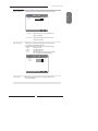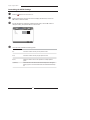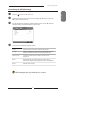
1
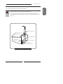
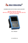
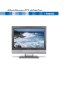
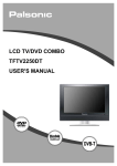
Widescreen LCD Television
FLU-2632/FLU-3232/
FLU-2632I/FLU-3232I/
FLU-2632D/FLU-3232D/FLU-3732D/FLU-4232D
a
20061005
This TV incorporates High-Definition Multimedia Interface (HDMITM) technology.
HDMI, the HDMI logo and High-Definition Multimedia Interface are trademarks or registered
trademarks of HDMI Licensing LLC.
DISPOSAL OF WASTE ELECTRONIC EQUIPMENT BY PRIVATE
HOUSEHOLDS WITHIN THE EUROPEAN UNION
This sign indicates that this product may not be disposed of with your regular
household waste. The recycling and separate collection of such products is
your responsibility. Please drop off the above-mentioned waste at a designated
place for recycling waste electrical and electronic equipment. If you do not know
where to drop off your waste equipment for recycling, please contact your local
city office or household waste collection service.
Warnings and Precautions
Warnings and Precautions
This symbol is intended to alert the user to avoid the risk of electric shock.
This equipment must not be disassembled by anyone except qualified service personnel.
WARNING
CAUTION
This symbol is intended to alert the user to the presence of important operating and
maintenance instructions in the literature accompanying the appliance.
To reduce the risk of fire or electric shock, do not expose this equipment to rain or moisture.
▪
▪
▪
▪
TO REDUCE THE RISK OF ELECTRIC SHOCK,
DO NOT REMOVE COVER (OR BACK).
NO USER-SERVICEABLE PARTS INSIDE.
REFER SERVICING TO QUALIFIED SERVICE PERSONNEL.
Use of controls, adjustments or performance of procedures other than those specified herein
may result in hazardous radiation exposure.
Important Safety Instructions
This symbol indicates caution points.
This symbol indicates actions that should not be done.
This symbol indicates actions that must be performed.
▪ Do not place the equipment on any uneven or unstable carts, stands, tables, shelves etc.
The equipment may fall, causing serious injury to children or adults and serious damage to
the equipment itself.
▪ Use only a cart or stand recommended by the manufacturer. This equipment and
recommended cart or stand should be handled with care. Quick stops, excessive force, and
uneven surfaces may cause the equipment and cart/stand to overturn.
▪ Do not disable the 3-wire grounding type plug. The grounding pin on the 3-prong plug is an
important feature. Removing the grounding pin will increase the risk of damaging the
equipment.
▪ If you can not fit the plug into the electrical outlet, contact an electrician to install a grounding
outlet.
▪ Always operate this equipment from the type of power source indicated on the rear of the
serial/model information label.
▪ Never overload wall outlets and extensions.
3
ENGLISH
To prevent any injuries, the following safety precautions should be observed in the installation, use,
servicing and maintenance of this equipment.
Before operating this equipment, please read this manual completely, and keep it nearby for future
reference.
Warnings and Precautions
▪ Use and handle the power cord with care. Do not place any heavy objects on the AC
power cord.
▪ Do not pull the AC power cord. Do not handle the AC power cord with a wet hand.
▪ Do not touch the power cord and antenna cable during lightning.
▪
Remove the plug from the wall outlet, if the equipment will not be used for a long period
of time.
▪
Do not place, use or handle this equipment near water.
▪
Never expose the equipment to liquid, rain, or moisture.
Seek for service if any of the above is spilled into the equipment.
▪
Do not expose the equipment to extreme temperature or to direct sunlight, as the
equipment may heat up and suffer damage.
▪
Do not install the equipment near any heat sources such as radiators, heat registers,
stoves, or any other apparatus that might produce heat.
▪
Do not attempt to service the equipment yourself.
▪
Opening and removing the covers may expose you to dangerous voltage or other
hazards and may void your warranty. Refer service to qualified personnel.
▪
Do not place or drop any other objects on top.
▪
Do not insert anything into the ventilation holes of your equipment.
Inserting any metal or flammable objects may result to fire or electric shock.
▪
Do not place the equipment on uneven or unstable carts, stands, tables, shelves etc.
The equipment may fall, causing serious injury to children or adults and serious damage
to the equipment itself. Always place the equipment on the floor or on a surface that is
sturdy, level, stable and strong enough to support the weight of the equipment.
▪
Do not block any ventilating openings. Leave an open space around the equipment.
Never place the equipment :
on a bed, sofa, rug, or any other similar surfaces; too close to drapes/curtains/walls, in a
bookcase, built-in cabinet, or any other similar places that may cause poor ventilation.
▪
Unplug this apparatus during lightning storms or when unused for long periods of time.
▪
Refer all servicing to qualified service personnel. Servicing is required when the
apparatus has been damaged in any way, such as power-supply cord or plug is
damaged, liquid has been spilled or objects have fallen into the apparatus, the apparatus
has been exposed to rain or moisture, does not operate normally, or has been dropped.
▪
Always remove the power cord from the outlet before cleaning the equipment.
▪
Never use liquid or aerosol cleaners on the equipment.
Clean only with a soft dry cloth.
▪
Only use attachments/accessories specified by the manufacturer.
4
Warnings and Precautions
Outdoor Antenna Safety Instructions
If an outdoor antenna is connected, follow the precautions below:
▪
When installing an outdoor antenna system, extreme caution should be taken to prevent
contact with power lines. Direct contact with power lines may be fatal and should be avoided
at all costs.
Antenna lead-in wire
Ground clamps
Antenna discharge unit
Electric service
equipment
Grounding conductors
Ground clamps
Power service grounding
EXAMPLE OF OUTDOOR ANTENNA GROUNDING
5
ENGLISH
▪ An outdoor antenna should not be located in any area where it could come in contact with
overhead power lines, or any other electric light or power circuits.
CONTENTS
Warnings and Precautions
Important Safety Instructions ....................................................................................... 3
Antenna Safety Instructions ......................................................................................... 5
Chapter 1 Introducing the LCD TV
Key Features ............................................................................................................... 7
Package Contents ....................................................................................................... 8
Setting Your LCD TV.................................................................................................... 9
Your LCD TV ...............................................................................................................11
Your Remote Control ................................................................................................. 13
Chapter 2 Installing the LCD TV
Connecting a TV Cable or an Antenna ...................................................................... 15
Connecting a VCR ..................................................................................................... 20
Connecting a Video Camera or Game Console ........................................................ 20
Connecting a DVD Player .......................................................................................... 22
Connecting a digital TV Cable Box or Digital Satellite Receiver ................................ 24
Connecting an AV Equipment with HDMI Connector ................................................. 25
Connecting an AV Equipment with DVI Connector .................................................... 26
Connecting an AV Equipment with SCART Connector .............................................. 27
Connecting a PC........................................................................................................ 28
Connecting an Audio Receiver ................................................................................. 29
Chapter 3 USING THE FEATURES
Using Picture-In-Picture .............................................................................................................................30
Wide Screen Viewing...................................................................................................................................32
Using Telextext Functions .........................................................................................................................33
Operating the Menu .....................................................................................................................................34
Customizing the VIDEO Settings...........................................................................................................37
Customizing the AUDIO Settings...........................................................................................................38
Customizing the SETUP Settings..........................................................................................................39
Using the Parantal Settings...................................................................................................................... 40
Customizing the TV Settings.................................................................................................................... 41
Troubleshooting.................................................................................................... 43
Display Modes........................................................................................................ 44
Specifications ........................................................................................................ 45
6
Chapter 1 Introducing the LCD TV
Chapter 1
Introducing the LCD TV
ENGLISH
Key Features
Various Audio/Video terminals for external equipment connection
▪
▪
▪
▪
▪
▪
▪
2 set of composite A/V input terminals
2 SCART input terminals
1 set of component Video input terminals
1 VGA/ Audio input terminal
2 HDMI/Auido input terminals
1 sets of Audio(L/R) output terminals
1 Headphone terminal
High Definition Multimedia Interface (HDMI)
▪ High Definition Multimedia Interface (HDMI) is a small, user-friendly interconnect that
can carry up to 5 Gbps of combined video and audio in a single cable. This system
eliminates the cost, complexity and confusion of multiple cables used to connect
current A/V systems.
HDTV Component Video Inputs
▪ Offers the best video quality for DVD(480p) and digital set-top-box (HD1080i, 720p)
connections.
3D Digital Noise Reduction
▪ This function can digitally reduce image noise to provide better picture quality.
Film-Mode Detection (3:2 Reverse Pull Down)
▪ This function can automatically detect content derived from film and adjust the
interlacer’s frame matching to provide a more natural-looking, clearer image of the
moving picture.
PIP Function
▪ The PIP/POP feature allows simultaneous viewing of video from two sources (TV,
VCR, DVD etc). Only one source’s audio is played at a time; the user may select which
source’s audio is heard.
7
Chapter 1 Introducing the LCD TV
Package Contents
Make sure all of the following contents are included.
LCD TV
Bottom Stand /
Screw Driver and 6 Screws
a
Remote Control/
AAA Batteries x 2
VIDEO Cable
Component Cable
POWER
P.MODE
SWAP
PIP
S.MODE
MTS
MUTE
CAPTION
SLEEP
P.SIZE
1
3
2
5
4
7
JUMP
6
8
9
0
ENT
AIR/CABLE
CH.
VOL.
SOURCE
EXIT
GUIDE
OK
INFO
LIST
MENU
FAV.CH
TIMER
FREEZE
Power Cord
AUDIO Cable
The power cord type may
be different depending on
your country’s power type.
Warranty Card
User Guide
Quick Guide
These items are all you need to set up and operate the LCD TV in its basic configuration.
Make sure all of the following contents are included. If you are missing any items,
please return this product to the original place of purchase.
8
Chapter 1 Introducing the LCD TV
Setting Your LCD TV
ENGLISH
How to install the TV Stand
If you prefer to mount your new Polaroid TV on a wall instead of attaching it to the stand,
please reference the instructions included in the wall mounting kit(not included).
Do not remove the packaging material from the TV before the stand is
attached.
Read all instructions before continuing with the stand installation.
a.
b.
Lift foam packaging material from the top of the LCD out of the box.
Lift LCD out of the box, with the bottom foam packaging material still attached, and place
onto a stable surface.
a
b
Protective bag
Stand
c.
d.
Shipping box
Table
Remove protective bag from LCD unit, but DO NOT remove the bottom foam packaging
material from the TV.
Locate the place on the back of the TV to attach the stand. Secure the stand to the LCD
with all six screws.
Unit
c
Table
Stand
Packaging material
d
Unit
Table
Screw x 6
Stand
Packaging material
9
Chapter 1 Introducing the LCD TV
How to setup the TV
Use a supplied antenna cable to connect the VHF/UHF signal to the LCD TV’s ANT. terminal
(refer to page 17).
Connect the AC power cord at the back of the TV and connect the power cord to wall outlet.
Insert the 2 batteries supplied in remote control.
Step1
Slide the back cover up to open the
battery compartment of the remote
control.
Step2
Insert two AAA size batteries.
Make sure to match the (+) and
( - ) ends of the batteries with
the (+) and ( - ) ends indicated
in the battery compartment.
Slide the cover back into place.
Do not use caustic cleaners (porcelain, stainless steel, toilet, or oven cleaner
etc.) on the remote, as it may suffer damage.
Connect an external A/V device (refer to pages 20-29).
10
Chapter 1 Introducing the LCD TV
Your LCD TV
Front/Right Side View and Controls
ENGLISH
LED
The LED light indicates when the LCD TV is
activated.
a
IR
Infrared
Receiver
VOLUME▲▼
Adjusts the volume up and down.
Selects the main-menu item and change
values for items when in the OSD mode.
VIDEO1 IN
VIDEO
Connects to the composite
Video and Audio output jacks
on external video equipment.
L
AUD IO
CHANNEL▲▼
Scans up and down through channels.
Selects sub-menu item when in the OSD
mode.
R
VIDEO1 IN
Headphone
MENU
Press once to display the OSD (on
screen display), press again to turn the
OSD off.
Connects to the external
headhone for private
listening.
INPUT
Chooses from different input signal
sources.
Turns the LCD TV on and into standby mode.
11
Chapter 1 Introducing the LCD TV
Rear View and Jacks
VIDEO2 IN
Connects to the composite VIDEO and AUDIO(L/R) output jacks on
external video equipment.
HDMI 1/HDMI 2 IN
Connects the all digital AV equipment with HDMI connector.HDMI
supports enhanced, high-definition video and two-channel digital
audio. The AUDIO(L/R) of HDMI IN is for DVI connection.
VGA IN
Connects the PC, or other AV equipment with VGA and AUDIO(L/R)
output jacks.
HDMI 1 IN
VGA /PC IN
HDMI 2 IN
COMPONENT IN
AUD IO
OUT
AUD IO IN
AUD IO IN
L
R
L
R
L
L
AUD IO IN
R
Y
Pb
Pr
L
R
TV CABLE
R
VIDEO
VHF/UHF IN
VIDEO2 IN
AUD IO IN
SCART 1
SCART 2
SCART1/SCART2 IN
Connects a piece of AV equipment with a SCART socket.
The SCART interface offers multiple signals(RGB, AV) with audio input/output
between the TV and external video equipment.
COMPONMENT IN
Connects to the DVD player, Digital Set-Top-Box, or other AV equipment with
component(YPbPr) video and audio output jacks.
AUDIO OUT
Connects to the AUDIO(L/R) input jacks on AV equipment.
TV CABLE
Connects RF input from VHF/UHF antenna or cable.
AC IN
Connects to the AC power cord.
12
Chapter 1 Introducing the LCD TV
Your Remote Control
POWER
POWER
Turns the LCD TV on and off.
2
SWAP
Swaps between the main and sub
window in PIP/POP mode.
3
FREEZE
Pressing FREEZE to freeze the current
picture, press again to restore the
picture.
4
PIP
Turns PIP/POP on and off.
5
I-II
Cycles through the TV sound options
(NICAN) : MONO/DUAL/STEREO
FAV.CH
Pressing FAV.CH displays favorite
channels.
11
3
FREEZE
SWAP
PIP
4
5
FAV.CH
7
6
SLEEP
P.SIZE
8
10
6
9
11
12
1
2
3
4
5
6
7
Turns on and off the Teletext function.
7
8
9
8
Mutes and restores the audio
JUMP
0
ENT
9
14
CH.
SOURCE
MENU
EXIT
OK
S.MODE
Cycles through the LCD TV sleep timer:
OFF/30/60/90/120 mins
10 P.SIZE
Cycles through Widescreen mode
settings :NORMAL /FULL/WIDE/ZOOM
11 0-9/ENT
Pressing a number selects a channel.
Following selection, pressing ENT
activates the channel, or channel
activates automatically in 3 seconds.
12 JUMP
Returns to previously selected channel.
13 INFO
Pressing once displays a variety of
information such as the current channel
and the input source.
14 VOL.+-
Increases and decreases volume.
15 CH.▲▼
Scans up and down the channels.
16 SOURCE
Pressing SOURCE displays the source
list, use ▲▼ to select the video
equipment connected to the video
inputs of your LCD TV : TV/VIDEO1/
VIDEO2/VIDEO3/VIDEO4/VIDEO5/
VIDEO6/VIDEO7/COMPUTER
13
INFO
VOL.
SLEEP
P.MODE
15
16
Not all regions support Teletext. Please check with your cable or satellite company.
13
ENGLISH
2
1
Chapter 2 Installing the LCD TV
POWER
17
EXIT
Exits the OSD menu.
18
MENU
Displays the OSD menu on the screen.
19
▲▼►◄
Cycles through OSD options and
selects individual menu items. OK
confirms option settings.
OK
FREEZE
SWAP
PIP
FAV.CH
SLEEP
20
S.MODE
Selects sound effect options: Surround/
Live/Dance/Techno/Classic/Soft/Rock/
Pop/Off.
21
P.MODE
Selects picture mode: Vivid/High-Bright/
Cinema/Sport/User
P.SIZE
1
2
3
4
5
6
7
8
9
JUMP
0
ENT
22
Accesses the TELETEXT items or
corresponding pages.
23
Displays the main index in TELETEXT
mode.
24
Displays the top, bottom or all of page,
to easily read in TELETEXT mode.
25
Freezes a multi-page passage on
screen inTELETEXT mode.
26
Reveals hidden information such as the
answer to a quiz in TELETEXT mode.
INFO
CH.
VOL.
SOURCE
MENU
EXIT
17
18
OK
19
20
21
S.MODE
22
23
P.MODE
24
25
26
Effective range:
The remote can control the LCD TV from up to 5m away, if pointed directly at the receiver.
14
Chapter 2 Installing the LCD TV
Chapter 2
Installing the LCD TV
Connecting a TV Cable or an Antenna
Antenna Connection
The antenna requirements for good color TV reception are more important than those for a black &
white TV reception. For this reason, a good quality outdoor antenna is strongly recommended.
The following is a brief explanation of the type of connection that is provided with the various antenna
systems.
■ A 75-ohm system is generally a round cable (not included) with IECtype connector that can easily be attached to a terminal without
tools.
IEC-type connector
75-ohm coaxial cable (round)
■ A 300-ohm system is a flat twin-lead cable (not included) that can
be attached to a 75-ohm terminal through a 300-75-ohm adapter
(not included).
300-ohm twin-lead cable (flat)
15
ENGLISH
Refer to the owner’s manual of any external equipment to be connected.
When connecting any external equipment, do not connect any AC power cords to wall outlets
until all other connections are completed.
Chapter 2 Installing the LCD TV
Use one of the following two diagrams when connecting an outdoor antenna.
A: Shows how to use a VHF/UHF combination outdoor antenna.
B: Shows how to use a separate VHF and/or UHF outdoor antenna.
A. Combination VHF/UHF antenna
VHF/UHF
Antenna
300/75-ohm adapter
(not included)
VHF/UHF
Antenna
300-ohm twinlead cable
75-ohm
coaxial cable
B. Separate VHF and/or UHF antennas
UHF
Antenna
Combiner
300-ohm twin(not included)
lead cable
OUT
IN
75-ohm
coaxial cable
300-ohm twinlead cable
16
VHF
Antenna
Chapter 2 Installing the LCD TV
Cable TV (CATV) Connection
ENGLISH
■ A 75-ohm coaxial cable connector is built into the set for easy hookup.
When connecting the 75-ohm coaxial cable to the set, connect the 75ohm cable into the ANT. terminal.
■ Some cable TV companies offer premium pay channels. Since the
signals of these premium pay channels are scrambled, a cable TV
converter/descrambler is generally provided to the subscriber by the
cable TV company.
This converter/descrambler is necessary for normal viewing of scrambled channels.
(Set your TV to channel 3 or 4, typically one of these channels is used. If this is unknown,
consult your cable TV company.)
For more specific instructions on installing cable TV, consult your cable TV company.
One possible method of connecting the converter/descrambler provided by your cable TV
company is shown in the diagram below.
RF switch
(not included)
OUT
VHF/UHF IN
2 set signal
splitter
(not included)
A
IN
B
Cable TV converter/
descrambler
(not included)
■ The RF switch (not included) is required to provide two inputs (A and B). Setting
the RF switch to position A allows viewing of all unscrambled channels by using
the TV channel keys.
■ Setting the RF switch to position B allows viewing of all scrambled channels via
the converter/descrambler by using the converter channel keys.
17
Cable TV Line
Chapter 2 Installing the LCD TV
Use a supplied antenna cable to connect the TV signal to the LCD TV’s TV CABLE
terminal.
TV CABLE
Connect the AC power cord at the back of the TV and connect the power cord to wall
outlet.
TV CABLE
VHF/UHF IN
This TV is equipped with a safety fuse. In the event of an electrical storm or power
outage the safety fuse is designed to protect your TV. If your TV has no power, check
the fuse by prying the cover off, following the illustration below. If the fuse is blown, visit
your local hardware store and ask for a 4A 250V - 5x20mm Time Lag Fuse (Slow Blow)
to replace the fuse.
Firm Plastic Prying Tool
(Using a metal tool may cause shock)
4A 250V
5x20mm
Fuse
Back of TV
BE SURE TO UNPLUG AC POWER CORD BEFORE REMOVING THE FUSE.
Press the
button on the remote to turn on the LCD TV.
Always disconnect the LCD TV from the power outlet when the LCD TV will
not be used for a long period of time.
The button on the front panel is only used for switching the LCD TV into
standby, it does not disconnect the device from the main voltage. To
completely disconnect the main voltage, please remove the power plug from
the socket.
18
Chapter 2 Installing the LCD TV
Press the SOURCE button on the remote to display the Source List. Use the ▲▼ buttons
to select TV, and press the OK button.
Main:
ENGLISH
D
TV(CABLE/AIR)
VIDEO1 (SIDE)
VIDEO2 (REAR)
VIDEO3 (SCART1)
VIDEO4 (SCART2)
VIDEO5 (YPbPr)
VIDEO6 (HDMI1)
VIDEO7 (HDMI2)
COMPUTER (VGA)
Press the MENU button on the remote control to display the Main menu, and use the
◄► buttons to select the TV.
Region Selection
Searching
Manual Scan
Update Search
Program Edit
Favorite
UK
Press the ▼ button to select Region Selection and select your country by the ◄►
buttons.
Press the ▼ button to select Channel Searching, and press the OK button. The
Channel Searching automatically creates a list of receivable channels. Press the
MENU button at any time to interrupt the memorization process.(the list cannot be
created if interrupted)
Searching
66.22MHz
PR Found:
2/100
1
When the Channel Searching finished,the Program Edit menu will appear (see page 41) :
Program Edit
PR
Freq
System
Name
Skip
1
2
3
4
5
6
7
8
9
10
49.75
-------------------
I
-------------------
---------------------
On
On
On
On
On
On
On
On
On
On
Swap
▲▼ Select
Insert
Copy
Delete
ENTER Edit
19
Chapter 2 Installing the LCD TV
Connecting a VCR
Rear of TV
HDMI 1 IN
VGA /PC IN
HDMI 2 IN
COMPONENT IN
AUD IO
OUT
AUD IO IN
AUD IO IN
L
R
L
R
L
L
AUD IO IN
R
Y
Pb
Pr
L
R
TV CABLE
R
VIDEO
VHF/UHF IN
VIDEO2 IN
AUD IO IN
SCART 1
SCART 2
AV Cable
Use a composite cable to connect the VCR’s composite video/audio jacks to the LCD TV’s
VIDEO2 IN jacks.
Connect all AC power sources, before turning on the power switch of the LCD TV or
other connected equipment.
Press the
button on the remote to turn on the LCD TV.
To watch a videotape, press the SOURCE button on the remote to select
VIDEO2( METHOD A).
20
Chapter 2 Installing the LCD TV
Connecting a Video Camera or Game Console
Rear of TV
ENGLISH
Right Side
HDMI 1 IN
VGA /PC IN
HDMI 2 IN
COMPONENT IN
AUD IO
OUT
VIDEO
L
AUD IO IN
AUD IO IN
AUD IO
L
R
L
R
L
L
AUD IO IN
Y
R
Pb
Pr
L
R
R
TV CABLE
R
VIDEO
VIDEO1 IN
VHF/UHF IN
VIDEO2 IN
AUD IO IN
SCART 1
SCART 2
or
AV Cable
PLAY STATION
Use a composite cable to connect the video camera’s or Game Console’s composite video/
audio jacks to the LCD TV’s VIDEO2 IN jacks or VIDEO1 IN jacks.
Connect all AC power sources, before turning on the power switch of the LCD TV or
other connected equipment.
Press the
button on the remote to turn on the LCD TV.
To watch a video via camera or Game Console, press the SOURCE button on the
remote to select VIDEO1/VIDEO2.
Not all cameras have the ability to connect to a TV. Please check your video camera
user guide for compatibility.
21
Chapter 2 Installing the LCD TV
Connecting a DVD Player
Rear of TV
HDMI 1 IN
VGA /PC IN
HDMI 2 IN
COMPONENT IN
AUD IO
OUT
AUD IO IN
AUD IO IN
L
R
L
R
L
L
AUD IO IN
R
Y
Pb
L
Pr
TV CABLE
R
R
VIDEO
VHF/UHF IN
VIDEO2 IN
AUD IO IN
SCART 1
SCART 2
Pb
Pr
COMPONENT/AUDIO Cable
A/V Cable
B
A
Pb
Pr
D V D PLA YER
METHOD A:
Use a composite cable to connect the DVD player’s composite video/audio jacks to the LCD
TV’s VIDEO2 IN jacks.
METHOD B:
Use a component cable to connect the DVD player’s component output jacks to the LCD TV’s
YPbPr IN input jacks.
Use an audio cable to connect the DVD player’s component audio jacks to the LCD TV’s
audio input jacks.
The component video jacks on your DVD player are sometimes labeled
YPbPr, or YCbCr. For an explanation of component video, see your DVD
player’s user guide.
22
Chapter 2 Installing the LCD TV
Connect all AC power sources, before turning on the power switch of the LCD TV or
other connected equipment.
button on the remote to turn on the LCD TV.
To watch a DVD, press the SOURCE button on the remote to select
VIDEO2( METHOD A), or VIDEO5 (METHOD B).
For best picture quality, if your equipment has component video output, use
a component cable instead of a composite video.
23
ENGLISH
Press the
Chapter 2 Installing the LCD TV
Connecting a Digital TV Cable Box or Digital Satellite Receiver
Rear of TV
HDMI 1 IN
VGA /PC IN
HDMI 2 IN
COMPONENT IN
AUD IO
OUT
AUD IO IN
AUD IO IN
L
R
L
R
L
L
AUD IO IN
R
Y
Pb
L
Pr
R
TV CABLE
R
VIDEO
VHF/UHF IN
VIDEO2 IN
SCART 1
AUD IO IN
SCART 2
Pb
Pr
COMPONENT/AUDIO Cable
Pb
Pr
Use a component cable to connect the satellite receiver’s/TV Cable Box’s component
(YPbPr) output jacks to the LCD TV’s component input jacks.
Use an audio cable to connect the satellite receiver’s/TV Cable Box’s component audio
jacks to the LCD TV’s audio input jacks.
Connect all AC power sources, before turning on the power switch of the LCD TV or
other connected equipment.
Press the
button on the remote to turn on the LCD TV.
To watch programs via satellite receiver or TV Cable Box, press the SOURCE button on
the remote to select VIDEO5.
24
Chapter 2 Installing the LCD TV
Connecting AV Equipment with HDMI Connector
Rear of TV
VGA /PC IN
HDMI 2 IN
COMPONENT IN
AUD IO
OUT
AUD IO IN
AUD IO IN
L
R
L
R
L
L
AUD IO IN
R
Y
Pb
Pr
ENGLISH
HDMI 1 IN
L
R
TV CABLE
R
VIDEO
VHF/UHF IN
VIDEO2 IN
AUD IO IN
SCART 1
SCART 2
or
HDMI Cable
AV EQUIPMENT
Use a HDMI cable to connect the AV equipment’s HDMI output jack to the LCD TV’s HDMI1/
HDMI2 IN jacks.
Connect all AC power sources, before turning on the power switch of the LCD TV or
other connected equipment.
Press the
button on the remote to turn on the LCD TV.
Press the SOURCE button on the remote to select VIDEO6 or VIDEO7.
The HDMI connector provides both video and audio signals. It is not
necessary to connect the audio cable.
25
Chapter 2 Installing the LCD TV
Connecting an AV Equipment with DVI Connector
Rear of TV
HDMI 1 IN
VGA /PC IN
HDMI 2 IN
COMPONENT IN
AUD IO
OUT
AUD IO IN
AUD IO IN
L
R
L
R
L
L
AUD IO IN
R
Y
Pb
Pr
L
TV CABLE
R
R
VIDEO
VHF/UHF IN
VIDEO2 IN
AUD IO IN
SCART 1
SCART 2
or
AUDIO Cable
AUD IO
L
R
DVI IN
HDMI-to-DVI Cable
AV EQUIPMENT
Use a HDMI-to-DVI cable to connect the AV equipment’s DVI output jack to the LCD TV’s
HDMI1/HDMI2 IN jacks.
Use an audio cable to connect the AV equipment’s audio output jacks to LCD TV’s HDMI
AUDIO jacks.
Connect all AC power sources, before turning on the power switch of the LCD TV or
other connected equipment.
Press the
button on the remote to turn on the LCD TV.
Press the SOURCE button on the remote to select VIDEO6 or VIDEO7 .
If the LCD TV is connected to AV equipment’s DVI connector, you will need
an HDMI-to-DVI cable or a HDMI adapter(not included).
26
Chapter 3 Using the LCD TV
Connecting an A/V Device with SCART Connector
Rear of TV
VGA /PC IN
HDMI 2 IN
COMPONENT IN
AUD IO
OUT
AUD IO IN
AUD IO IN
L
R
L
R
L
L
AUD IO IN
Y
R
Pb
Pr
ENGLISH
HDMI 1 IN
L
R
TV CABLE
R
VIDEO
VHF/UHF IN
VIDEO2 IN
AUD IO IN
SCART 1
SCART 2
or
D V D PLA YER
SCART Cable
Use a SCART cable to connect the external A/V device’s SCART socket to the LCD TV’s
VIDEO3(SCART1) or VIDEO4(SCART2) jack.
Connect all AC power sources, before turning on the power switch of the LCD TV or
other connected equipment.
Press the
button on the remote to turn on the LCD TV.
Press the SOURCE button on the remote to select VIDEO3 or VIDEO4 .
The SCART 1 socket offers a multi-signal interface, including C-video(input/
output),S-video, RGB audio input and audio output.
The SCART 2 socket offers a multi-signal interface, including C-video(input),
S-video, RGB audio input and audio output.
27
Chapter 3 Using the LCD TV
Connecting a PC
Rear of TV
HDMI 1 IN
VGA /PC IN
HDMI 2 IN
COMPONENT IN
AUD IO
OUT
D IO IN
AUD IO IN
L
R
L
R
L
L
AUD IO IN
Y
R
Pb
Pr
L
TV CABLE
R
R
VIDEO
VHF/UHF IN
VIDEO2 IN
AUD IO IN
SCART 1
SCART 2
AUDIO Cable
VGA Cable
PC
Use a VGA cable to connect the PC’s VGA output jack to the LCD TV’s VGA input jack.
Use an audio cable to connect the PC’s audio output jacks to LCD TV’s.
Connect all AC power sources, before turning on the power switch of the LCD TV or
other connected equipment.
Press the
button on the remote to turn on the LCD TV.
Press the SOURCE button on the remote to select COMPUTER.
Press the OK button to automatically adjust the display settings to optimize
performance based on the VGA mode.
28
Chapter 3 Using the LCD TV
Connecting an Audio Receiver
For better sound quality, you may want to play the LCD TV audio through your stereo system.
ENGLISH
HDMI 1 IN
HDMI 2 IN
VGA /PC IN
AUD IO IN
AUD IO IN
L
R
L
R
L
COMPONENT IN
AUD IO
OUT
L
AUD IO IN
R
Y
Pb
L
Pr
R
TV CABLE
R
VIDEO
VHF/UHF IN
VIDEO2 IN
AUD IO IN
SCART 1
SCART 2
AUDIO Cable
Audio Receiv
er
Connecting to Audio Receiver:
Use an audio cable to connect the audio receiver’s audio LINE IN jacks to LCD TV’s
AUDIO OUT jacks.
Connect all AC power sources, before turning on the power switch of the LCD TV or
other connected equipment.
Press the
button on the remote to turn on the LCD TV.
29
Chapter 3 Using the LCD TV
Chapter 3
USING THE FEATURES
Using Picture-In-Picture
The PIP/POP feature allows simultaneous viewing of video from two sources (TV, VCR, DVD etc).
Only one source’s audio is played at a time; the user may select which source’s audio is heard.
Press the PIP button once to enter Picture-in-Picture mode.
Main
Sub
a
▪ Press ◄ ► to toggle the audio source between the main window and
the sub window.
▪ Press
the SWAP button to swap
the pictures between the main and sub
SUB
MAIN
windows.
▪ Press the OK button to change the position of the second window.
1
2
3
5
4
▪ Press ◄ ► to activate either the main or sub windows, then press the
SOURCE button to display the Input List:
Sub
VIDEO5 (YPbPr)D
VIDEO6 (HDMI1)
VIDEO7 (HDMI2)
COMPUTER (VGA)
Press ▲▼ to change input source and press the OK button.
30
Chapter 3 Using the LCD TV
Press the PIP button again to view images side by side.
ENGLISH
Main
Sub
a
▪ Press ◄ ► to toggle the audio source between the main window and the sub window.
▪ Press the SWAP button to swap the pictures between the main and sub windows.
a
▪ Press ◄ ► to activate either the main or sub window, then
press the SOURCE button to display the Input List:
Press ▲▼ to change input source and press the OK button.
Sub
VIDEO5 (YPbPr) D
VIDEO6 (HDMI1)
VIDEO7 (HDMI2)
COMPUTER (VGA)
Press the PIP button again to exit.
If the input source of the main window is TV/C-VIDEO/HDMI, the input source of the
second window will by default be SCART/YPbPr/VGA. Press the SWAP button to switch
the input sources between the main window and the second window.
:PIP/POP available, :PIP/POP not available
Sub
Main
Main
TV
VIDEO
SCART1 SCART2 YPbPr
TV
VIDEO
SCART1
SCART2
YPbPr
HDMI
VGA
31
HDMI
VGA
Chapter 3 Using the LCD TV
Widescreen Viewing
Widescreen function allows viewing of 4:3/16:9 images in wide screen mode, cycling through the
following wide screen settings. Press the P.SIZE button repeatedly to select the screen format
you want.
NORMAL
Displays at 4:3 aspect ratio.
FULL
Stretches the image vertically and
horizontally to keeps the image size
consistent in the center of the screen and
stretches the sides.
WIDE
Stretches the image vertically and
horizontally to fill the screen at 1:1.85
aspect ratio.
ZOOM
Stretches the image vertically and
horizontally to fill the screen at 1:2.35
aspect ratio.
32
Chapter 3 Using the LCD TV
Using TELETEXT Functions
Press
switch on or off teletext display.
POWER
FREEZE
SWAP
PIP
SLEEP
P.SIZE
FAV.CH
1
2
1
2
3
4
5
6
7
8
9
JUMP
0
ENT
In TELETEXT mode, There are four colour
coded
subject headings at the
bottom of the screen.
To access more information about one of these
subjects, press the appropriate colored button.
Press
button once for the text to occupy
the top half of the screen, press again for it to
occupy the bottom half, and press again to
return to full page.
INFO
CH.
VOL.
Press
button once to reveal hidden words
(concealed information) and press again to
hide.
SOURCE
MENU
EXIT
Press the CH▲▼ buttons to scroll between
pages, or use the 0-9 buttons to enter the
number of the page required. Example: page
120, enter 1 2 0. The page number is displayed
at the top let corner of the screen.
Press
button to hold the TELETEXT page
when viewing multiple pages of information,
press again to return to automatic page update.
OK
Press
page.
S.MODE
3
7
P.MODE
4
6
5
33
button to return to the main index
ENGLISH
The TELETEXT feature displays all sorts of information provided by the information system
company on your screen, such as news, sports, travel offers, weather, film & theater
reviews, net issues etc.
Chapter 3 Using the LCD TV
Operating the Menu
Press the
button to turn the LCD TV on.
Press the MENU button on the remote control, the on-screen menu will appear on the
screen. Use the ◄► buttons to select your main menu option.
VIDEO MENU:
Allows you to make adjustments to your picture settings.
▪ If the signal source is VGA, the VIDEO MENU
appears as:
Picture Mode
Contrast
Brightness
Auto Setting
Phase
Manual Clock
Display Adjustment
Color Temperature
Noise Reduction
▪ If the signal source is TV/VIDOE/SCART/YPbPr/
HDMI, the VIDEO MENU appears as:
Picture Mode
Contrast
Brightness
Saturation
Hue
Sharpness
Color Temperature
Noise Reduction
Vivid
75
55
20
128
Nature
Off
AUDIO MENU:
Allows you to customize the audio options and effects.
Bass
Treble
Balance
Sound Effect
50
50
0
Surround
34
Vivid
80
50
70
0
4
Nature
Off
Chapter 3 Using the LCD TV
TV MENU:
Allows you to edit and label channels.
ENGLISH
Region Selection
Searching
Manual Scan
Update Search
Program Edit
Favorite
UK
SETUP MENU:
Allows you to set up a variety of features: Language, factory reset, V-Chip, Parental Control, Gamma, etc.
Parental
Language
OSD Transparent
Gamma
Default
English
On
Middle
Use the ▲▼ buttons to select an option of the sub-menu, and press the OK button. While in
adjustment mode, and use the ◄► buttons to change the value of the item.
Press the EXIT button to exit the menu.
35
Chapter 3 Using the LCD TV
Customizing the VIDEO Settings
Press the
button to turn the LCD TV on.
Press the MENU button on the remote control to display the Main menu, and use the
◄► buttons to select the VIDEO.
Use the ▲▼ buttons to highlight an individual VIDEO option, use the ◄► buttons to
change the setting, and press the MENU to exit the menu
▪ If the signal source is VGA, the VIDEO MENU
appears as:
Picture Mode
Contrast
Brightness
Auto Setting
Phase
Manual Clock
Display Adjustment
Color Temperature
Noise Reduction
▪ If the signal source is TV/VIDOE/SCART/YPbPr/
HDMI, the VIDEO MENU appears as:
Picture Mode
Contrast
Brightness
Saturation
Hue
Sharpness
Color Temperature
Noise Reduction
Vivid
75
55
20
128
Nature
Vivid
80
50
70
0
4
Nature
Off
Off
The VIDEO menu includes the following options:
Picture Mode
Cycles among display types: Vivid/High-Bright/Cinema/Sport/User
Contrast
Controls the difference between the brightest and darkest regions of
the picture.
Brightness
Controls the overall brightness of the picture.
Auto Setting
Phase
Press the OK button to automatically adjust the display settings to
optimize performance based on the VGA mode.
Controls the signal phase, which can improve focus clarity and image
stability based on the VGA mode.
Saturation
Controls the color intensity.
Hue
Controls the difference between the green and red regions of the
picture.
Sharpness
Increase this setting to see crisp edges in the picture; decrease it for
soft edges.
Manual Clock
Controls the width of the picture based on the VGA mode.
36
Chapter 3 Using the LCD TV
Display adjustment
Press the OK button to enter the Display adjustment setting:
Color temperature
128
20
▪ H Position
Adjusts the position of the picture left and
right in the window.
▪ V Position
Adjusts the position of the picture up and
down in the window.
Adjusts color components independently to achieve a warm
or cool effect: Cool/Middle/Warm/User
Press the OK button to enter the color temperature setting:
▪ Warm:
Increases red tint
▪ Nature:
Increases natural tint
▪ Cool:
Increases blue tint
▪ User:
Allows the user to adjust red, green and blue
color component levels independently.
Color Temp.R
Color Temp.G
Color Temp.B
Noise Reduction
124
120
120
Select to reduce the noise level of connected equipment:Off/
Low/ Strong /Middle.
37
ENGLISH
H Position
V Position
Chapter 3 Using the LCD TV
Customizing the AUDIO Settings
Press the
button to turn the LCD TV on.
Press the MENU button on the remote control to display the Main menu, and use the
◄► buttons to select the AUDIO.
Use the ▲▼ buttons to highlight an individual AUDIO option, use the ◄► buttons to
change the setting, and press the MENU to exit the menu
Bass
Treble
Balance
Sound Effect
50
50
0
Surround
The AUDIO menu includes the following options:
Bass
Controls the relative intensity of lower-pitched sounds.
Treble
Controls the relative intensity of higher pitched sounds.
Balance
Adjusts the relative volume of the speakers in a multiple speaker
system.
Sound Effect
Allows selection of an audio-enhancement technique from among the
following options: Surround/Live/Dance/Techno/Classic/Soft/Rock/Pop/
Off.
38
Chapter 3 Using the LCD TV
Customizing the SETUP Settings
button to turn the LCD TV on.
Press the MENU button on the remote control to display the Main menu, and use the
◄► buttons to select the SETUP.
Use the ▲▼ buttons to highlight an individual SETUP option, use the ◄► buttons to
change the setting, and press the MENU to exit the menu.
Parental
Language
OSD Transparent
Gamma
Default
English
On
Dark
The SETUP menu includes the following options:
Parental
Allows to setup the Parental Lock options(see page 39).
Language
Selects to display all on-screen menus in your language of choice :
English/French/Spanish/Italian/German/Russian/Portuguese.
OSD Transparent
Controls the translucence of the OSD on-screen menus’s
background.
Gamma
Default
Allows adjustment of the display’s gamma correction,which
finetunes both brightness and red/green/blue ratios: On/Off/Middle.
Restores factory settings.
OSD languages will vary depending on country.
39
ENGLISH
Press the
Chapter 3 Using the LCD TV
Using the Parental Settings
The Parental blocking can be set up on the TV to block a Channel or a Video Source.
Use the ▼ button to select the Parental, and press the OK to display the Parental
menu.
Channel Lock
Video Lock
Change Password
1
VIDEO5(YPbPr)
Use the Parental function, must enter a four-digit password. The factory password is
0000.
OK
Cancel
You need your password for any future access into the Parental Setting,
The Parental menu includes the following options:
Channel Lock
Selects to block a TV channel.
Use the ◄► buttons to select the channel you want to lock.
Press the OK button to confirm.
Video Lock
Selects to block a Input source signal.
Use the ◄► buttons to select the input video you want to lock.
Press the OK button to confirm.
Change Password
Selects to change your password.
Press the OK button to display the password confirm menu.
Use 0-9 keys on the remote control to enter a new four-digit
password, and then confirm the new password by entering it
again.
40
Chapter 3 Using the LCD TV
Customizing the TV Settings
button to turn the LCD TV on.
Press the MENU button on the remote control to display the Main menu, and use the
◄► buttons to select the TV.
Use the ▲▼ buttons to highlight an individual TV option, use the ◄► buttons to
change the settings, and press the MENU exits the menu.
Region Selection
Searching
Manual Scan
Update Search
Program Edit
Favorite
UK
The TV menu includes the following options:
Region Selection
Allows selection of regional TV systems: Western Europe, UK
Searching
Press the OK button, the Searching automatically creates a list
of receivable channels.
Manual Scan
Allows to set up TV channel manually.
Press the OK button to display the Manual Scan menu:
PR Start
Start From
Start Search
2
50.00MHz
PR Start: Press the ◄► buttons to assign a program number for
the channel.
Start From: Press the ◄► buttons to assign the frequency value
for the channel.
Press the ▼ button to select Start Search, and press the OK
button. The number of the channel is stored.
Update Search
Allows to re-scan TV channel automatically.
41
ENGLISH
Press the
Chapter 3 Using the LCD TV
Program Edit
Allows Swap/Insertion/addition/removal of channels on the channel list.
Press the OK button to display the Program Edit menu:
Program Edit
PR
Freq
System
Name
Skip
1
2
3
4
5
6
7
8
9
10
49.75
-------------------
I
-------------------
---------------------
On
On
On
On
On
On
On
On
On
On
Swap
▲▼ Select
Insert
Copy
Delete
ENTER Edit
Press the ▼ button to select the desired channel, and press the
OK button on the remote to display the PR menu:
PR Number
PR Name
Sound System
Frequency
Fine Tuning
Skip
Store
2
BCC
----On
Press the ▼ ▲ buttons to select the item, and press the OK
button to edit.
Press the ◄ ► buttons to change the value of the selected
item.
Use the ▼ button to select PR Name, and press the OK button
to display the Channel Name Edit menu.
▪ Use the ▼▲◄► buttons to select the characters (maximum
of 6 characters) and press OK key to confirm.
Use the ▼ button to select Store, and press the OK button
Favorite
Select Favorite from the TV option and press the OK button.
The Favorite Channel list appears:
Edit
▪
▪
▪
▪
Delete
Empty
View
Edit
To add the current channel to the list of Favorite Channels.
Press 0-9 buttons to enter the desired channels.
Delete
To remove a channel from the list of Favorite Channels.
Empty
To clear all Favorite Channels.
View
To watch the selected channel of Favorite Channels.
42
Specifications
TROUBLESHOOTING
TV will not turn on
Make sure the power cord is plugged in, then press the
button on the remote.
The batteries in the remote control may be exhausted.
Replace the batteries.
No picture, no sound
Check the interface cable between TV and antenna/cable TV.
Press the
button on the remote.
Press the SOURCE button on the remote repeatedly to select the connected video
sources.
Poor picture, sound OK
Check the interface cable between TV and antenna/cable TV.
Try another channel, the station may have broadcast difficulties.
Adjust the Brightness/Contrast options in the VIDEO Menu.
Picture OK, poor sound
Sound may be muted. Press the
button on the remote.
Press the VOL+ button to increase the volume.
Audio noise
Move any infrared equipment away from the TV.
“Polaroid” and “Polaroid and Pixel” are trademarks of Polaroid Corporation, Waltham, MA,
USA. For service, support and warranty information, visit www.polaroid.com.
43
ENGLISH
Before consulting service personnel, check the following chart for a possible
cause of problem and for a possible solution.
Specifications
DISPLAY MODES
The screen resolution has been optimized during production for the display modes listed below.
If the signal from the system equals the standard signal mode, the screen adjusts automatically. If the
signal from the system does not equal the standard signal mode, adjust the screen resolution by referring
to your video card user guide, otherwise there may be no video.
Video signal: (VGA Standard)
Vertical
Frequency(Hz)
Horizontal
Frequency(kHz)
640 x 350
85
37.9
640 x 400
85
37.9
720 x 400
85
37.9
640 x 480
60
31.5
72
37.9
75
37.5
85
43.3
56
35.1
60
37.9
72
48.1
75
46.9
Resolution (Dot X Line)
800 x 600
1024 x 768
85
53.7
60
48.4
70
56.5
75
60.0
85
68.7
1152 x 864
75
67.5
1280 x 960
60
60.0
1280 x 1024
60
64.0
1366 x 768
60
47.7
44
Specifications
SPECIFICATIONS
FLU-2632/FLU2632I/FLU-2632D
FLU-3232/FLU3232I/FLU-3232D
Panel Size
27” TFT LCD
32” TFT LCD
Brightness
500
500
Contrast Ratio
1200:1
800:1
MODEL
LCD Panel
Max. Resolution
Input Connector
1366x768
1366x768
VIDEO/AUDIO(L/R)
2
2
SCART
2
2
YPbPr/AUDIO(L/R)
1
1
VGA/AUDIO(L/R)
1
1
HDMI/AUDIO(L/R)
2
2
AUDIO OUT(L/R)
1
1
HEADPHONE
1
1
Power Source
AC100~240V, 50/60HZ, 3.0A AC100~240V, 50/60HZ, 3.0A
Power Consumption
200 W, standby <3 W
200 W, standby < 3 W
Dimension (W x H x D)
67.8 x 56.1 x 20.1 cm
80.5 x 63.5 x 21.3 cm
WEIGHT
14.5 kgs
17.9 kgs
FLU-3732/FLU3732I/FLU-3732D
FLU-4232/FLU4232I/FLU-4232D
Panel Size
37” TFT LCD
42” TFT LCD
Brightness
500
500
Contrast Ratio
1000:1
1200:1
MODEL
LCD Panel
Max. Resolution
Input Connector
1366x768
1366x768
VIDEO/AUDIO(L/R)
2
2
SCART
2
2
YPbPr/AUDIO(L/R)
1
1
VGA/AUDIO(L/R)
1
1
HDMI/AUDIO(L/R)
2
2
AUDIO OUT(L/R)
1
1
HEADPHONE
1
1
Power Source
AC100~240V, 50/60HZ, 3.0A AC100~240V, 50/60HZ
Power Consumption
200 W, standby <3 W
300 W, standby < 3 W
Dimension (W x H x D)
93.0 x 71.6 x 23.9 cm
105.2 x 79.1 x 24 cm
WEIGHT
24.5 kgs
31.3 kgs
Specifications are subject to change without notice.
45