1
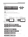
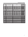
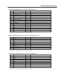
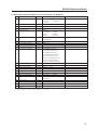
RS-232 Command Reference Manual
For PIONEER PDP-505CMX Plasma Display Panel
January 2006
Document Version 1.0
Product specifications and functions subject to change.
Please check with your authorized Pioneer dealer or distributor.
RS-232C Adjustment Mode
1.0 RS-232C Adjustment Mode
This display panel has an RS-232C terminal. It is possible to use a PC to make adjustments and settings.
1.1 About the RS-232C Adjustment Mode
1) Adjustments in the RS-232C adjustment mode:
• The adjustments are written to the same memory area as for the integrator mode. Refer to section 5.4.4,
“PICTURE, White Balance and SCREEN Position Adjustment Values Memory Area Tables" (pg. 211).
2) Display screen in the RS-232C adjustment mode:
––
1 2 8 0 X 1 0 2 4@6 0H z
• The screen appears as shown to the right.
The set ID is display in the ‘– –’ area in the upper left corner
of the screen.
AD J U S T ME N T
Notes
(1) Always assign an ID before using the RS-232C adjustment mode. Also, include the ID for the set
to be controlled or adjusted in the RS-232C command. For details, refer to section 5.5.2, “Interface"
(pg. 217).
(2) There are some RS-232C commands that can be used in the normal-operation mode.
For details refer to section, 5.5.5, “List of RS-232C Commands" (pg. 221).
(3) Some adjustment values and items set by RS-232C commands are stored in memory while other values
sand settings are not. For details, refer to section 5.5.5, “List of RS-232C Commands" (pg. 221).
Also, when storing final values in memory, the conditions described in section 5.1.5, “Last Memory"
(pg. 152), must be satisfied.
(4) <DIN>/<DIY> (OSD display disable/enable setting)
The following items can be displayed regardless of the setting:
• Menu display (menu mode, integrator mode)
• Warnings before Auto Power OFF or Power Management operation
• Warning of high temperature inside the set
• Display announcing that the FUNCTIONAL LOCK is set, and the FUNCTIONAL LOCK setting display
• Display call (including holding a button down)
(5) The RS-232C adjustment mode is automatically cancelled in the following cases:
• When the [STANDBY/ON] or [MENU] button is pressed
(6) Cancel the Integrator mode before entering the RS-232C adjustment mode.
(6) When controling the panel using RS-232C commands, control both the input signal and the power. If
the power is ON when there is no signal, the display continues to have a weak discharge. A discharge
could affect the life of the display.
2
RS-232C Adjustment Mode
1.2 Interface
1) Connector
D-sub 9 pins (male)
2) Pin layout
Pin No.
1
2
3
4
5
1
Signal
NC (not connected)
TxD (Transmit Data)
RxD (Receive Data)
NC (not connected)
GND
Pin No.
6
7
8
9
5
Signal
NC (not connected)
NC (not connected)
RTS (Request To Send)
NC (not connected)
6
9
3) Baud Rate
9600 bps (standard)
(switch-able to 1200, 2400, 4800, 19200, 38400 bps)
Note
The panel's baud rate should be set to match the computer's baud rate.
Also, when extending the RS-232C cable over a long distance, lower the baud rate.
4) Data format
Start: 1 bit
Data: 8 bit
Parity: 0 (no parity)
Stop: 1 bit
5) Connection
Control PC
(with D25 serial port )
RXD 3
TXD 2
CTS 5
GND 7
Plasma Display
(PDP-505CMX/50MXE10/50MXE11)
(PDP-504CMX/50MXE1/50MXE1-S)
(PDP-434CMX/43MXE1/43MXE1-S)
2
3
2
Plasma Display
(PDP-505CMX/50MXE10/50MXE11)
(PDP-504CMX/50MXE1/50MXE1-S)
(PDP-434CMX/43MXE1/43MXE1-S)
Control PC
(with D9 serial port)
(with D9 serial port)
2 TXD
3 RXD
8 RTS
5 GND
RXD 2
TXD 3
CTS 8
GND 5
* D-sub 9-pin/D-sub 25-pin conversion tables are now available on the market.
2
3
2
2 TXD
3 RXD
8 RTS
5 GND
Straight Cable
6) Protocol
From the computer to the display
(1) When sending one command at a time:
STX (02 hex)
ID (2 Byte)
COMMAND (3 Byte or 6 Byte)
ETX (03 hex)
(2) When numerical direct commands are possible:
STX (02 hex)
ID (2 Byte)
COMMAND (3 Byte)
ARGUMENT (3 Byte)
ETX (03 hex)
COMMAND: 3 Byte (ASCII)
ARGUMERNT: 3 Byte (ASCII)
(3) Echo back
STX (02 hex)
COMMAND (3 Byte or 6 Byte)
ETX (03 hex)
When the received command is a numerical direct effect command, numerical data is returned.
STX (02 hex)
COMMAND (3 Byte)
ARGUMENT (3 Byte)
ETX (03 hex)
When the received command is invalid, ‘ERR’ is returned.
STX (02 hex)
ERR (3 Byte)
ETX (03 hex)
When the received command cannot be processed (when PON is received, when the power
is already ON, etc.), ‘XXX’ is returned.
STX (02 hex)
XXX (3 Byte)
ETX (03 hex)
3
RS-232C Adjustment Mode
1.3 ID Assignment
After connecting to a computer, the PC can assign an ID for each plasma display panel.
Commands: <IDC> (ID CLEAR) ........ Clears the assigned ID
<IDS> (ID SET) ............. Assigns an ID
IDS is only effective when an ID is not assigned.
Also, IDs are set starting from the set closest to the PC.
Example: Case of 4 displays (assigning IDs with the PC for the first time)
Connect each unit as shown below.
Refer to section 5.5.4, “Combination Connection" (pg. 219).
PC
Set #1
±
ID = 01 OUT
Set #2
IN
ID = 02 OUT
Set #4
Set #3
IN
ID = 03 OUT
IN
ID = 04
RS-232C connection
Sent commands:
1 <∗∗AJY>
2 <01 IDS>
‘
3 <∗∗AJY>
4 <02 IDS>
‘
5 <∗∗AJY>
6 <03 IDS>
‘
7 <∗∗AJY>
8 <04 IDS>
By sending RS-232C commands in this order, it is possible to assign an ID for each unit.
Units for which an ID has been set can only receive commands with an ID attached. Attach an ID before sending a
command.
ID characters can include 0 - 9 and A - F (there is no distinction between upper and lower case letters).
.
An ∗ (asterisk) can be used as follows:
<∗∗IDC>: Clear the IDs assigned for all sets
<∗1AJY>: Only a set with the second digit as 1 enters the RS-232C adjustment mode
<2∗IN1>: Only input of a set with the first digit as 2 is set to INPUT1
Precautions when assigning IDs
Units that were connected after a set whose ID was cleared cannot be operated with RS-232C commands.
After assigning a setting as shown in the figure above and <∗∗AJY> =<∗∗
IDC> is performed, the IDs for all the sets
from Set #1 to Set #4 are cleared. Only the one set (Set #1) that is directly connected to the PC can be controlled.
Furthermore, by performing <∗∗ AJY> = <01 IDS>, it again becomes possible to control the second set (Set #2). By
setting IDs in the same way for the other sets, it again becomes possible to control the sets connected in succession.
Note
When the IDs are set and one or both of the IDs before a command are sent from the PC as a ∗, there is no echo
back. When sending more commands, wait 6 seconds before sending the next command.
Example) When ∗∗OOO and ∗1OOO or 1∗OOO (OOO is the command) are sent from the PC, operation is performed
but there is no echo back.
4
RS-232C Adjustment Mode
1.4 Combination Connection
When performing control and adjustment, it is easiest to connect several panels to one PC.
By performing a combination connection and assigning IDs to the displays, it is possible to control and adjust several
panels at the same time or separately.
Connection method:
Connect the panels as shown below. Control and adjust the units with the PC.
Second Panel
First Panel
IN
PC
OUT
COM BIN ATION
OUT
IN
RS-232 C
OUT
IN
RS-232 C
COM BIN ATION
IN
Third Panel
OUT
COM BIN ATION
RS-232 C
IN
OUT
Combination cable
Combination cable
Note
Only the combination IN terminal or RS-232C terminal can be used at the same time on one panel. Connecting them
at the same time could cause errors or cause other problems so do not connect them at the same time. Also,
do not connect pairs of combination IN terminals or combination OUT terminals. Doing so could cause errors or
other problems.
It is possible to use a general-purpose mini DIN 6-pin (straight) cable for the combination cable.
Note
To output RS-232C signals from the combination OUT terminal, an ID must be assigned.
For details, refer to section, 5.5.3, “ID Assignment" (pg. 218).
5
RS-232C Adjustment Mode
Under the connection conditions shown below, up to 16 panels can be controlled and operated.
Conditions: 1 Length of RS-232C cable connecting PC to PDP-505CMX/PDP-50MXE10/PDP-50MXE11/PDP-504CMX/
PDP-50MXE1/PDP-50MXE1-S/PDP-434CMX/PDP-43MXE1/PDP-43MXE1-S: 5 m
2 Combination cable length: 5 m each
3 Wire specifications for linking cable: Mini Din 6-pin straight (7 strand cable)
For 1 strand, suitable for AWG28:
Cross-section area = 0.08 mm2
≠
7 strands × π r2 = 7 × 3.14 × 0.062 = 0.079 mm2 ≠ 0.08 mm2
PC
PDP-505CMX/PDP50MXE10/
PDP-50MXE11/
PDP-504CMX/PDP-50MXE1/
PDP-50MXE1-S/
PDP-434CMX/PDP-43MXE1/
PDP-43MXE1-S
1
RS-232C
5m
OUT
IN
2
OUT
Combination cable 5m
IN
3
OUT
IN
#
Note
For details about the number of displays that can be connected in series using the video OUT terminal (INPUT1, 4), refer to
section 2.3, “Controls and Connectors" (pg. 16).
6
RS-232C Adjustment Mode
1.5 List of RS-232C Commands
How to read this Table
• RS-232C adjustment validity : Indicates whether the RS-232C adjustment mode can be used
• Normal validity
: Indicates whether the normal-operation mode can be used
• Numerical direct validity
: With a 3-digit number attached to the end of a command, the
command directly sets that adjustment value
• ‡ or ¶: Valid, No mark: Invalid
(NOTE) ¶ values are not stored in the last memory.
Command name
Remarks
AJY (232C integrator) Display
RS-232C
Numerical
Normal
Adjustment
Direct
Validity
Validity
Validity
[A]
AJN
–
Terminates the 232C integrator adjustment mode.
AJY
ADJUST: ON
Starts the 232C integrator adjustment mode.
AMN
AUDIO MUTING: OFF
Turns OFF the audio mute.
AMY
AUDIO MUTING: ON
Turns ON the audio mute.
AST
AUTO SET UP
Executes AUTO SETUP.
BHI
B HIGH: ∗∗∗
Adjusts B. HIGH.
BLW
B LOW: ∗∗∗
Adjusts B. LOW.
BRA
BAUD RATE: #####-232C
Displays the current baud rate.
BRAS01
BAUD RATE: 1200-232C
Sets the UART setting to 232C (1200BPS).
BRAS02
BAUD RATE: 2400-232C
Sets the UART setting to 232C (2400BPS).
BRAS03
BAUD RATE: 4800-232C
Sets the UART setting to 232C (4800BPS).
BRAS04
BAUD RATE: 9600-232C
Sets the UART setting to 232C (9600BPS).
BRAS05
BAUD RATE: 19200-232C
Sets the UART setting to 232C (19200BPS).
BRAS06
BAUD RATE: 38400-232C
Sets the UART setting to 232C (38400BPS).
BRT
BRIGHTNESS: ∗∗∗
Adjusts the brightness.
BSL
B SIDE MASK LEVEL: ∗∗∗
Adjusts the BLUE side mask.
¶
¶
¶
¶
¶
¶
‡
[B]
‡
‡
¶
‡
‡
‡
‡
‡
‡
‡
‡
‡
‡
‡
‡
‡
‡
‡
‡
‡
¶
‡
‡
‡
‡
‡
‡
‡
‡
‡
‡
¶
‡
‡
‡
‡
¶
‡
‡
‡
‡
‡
‡
‡
‡
‡
‡
‡
‡
‡
‡
[C]
CFR
CLOCK: ∗∗∗
Adjusts the CLOCK (PLL frequency).
CGB
COLOR DETAIL BLUE: ∗∗∗
Adjusts color detail BLUE.
CGC
COLOR DETAIL CYAN: ∗∗∗
Adjusts color detail CIAN.
CGG
COLOR DETAIL GREEN: ∗∗∗
Adjusts color detail GREEN.
CGM
COLOR DETAIL MAGENTA: ∗∗∗
Adjusts color detail MAGENTA.
CGR
COLOR DETAIL RED: ∗∗∗
Adjusts color detail RED.
CGY
COLOR DETAIL YELLOW: ∗∗∗
Adjusts color detail YELLOW.
CLS
COLOR SYSTEM: #####
Displays the current color system.
CLSS01
COLOR SYSTEM: AUTO
Sets the color system to AUTO.
CLSS02
COLOR SYSTEM: NTSC
Sets the color system to NTSC.
CLSS03
COLOR SYSTEM: PAL
Sets the color system to PAL.
CLSS04
COLOR SYSTEM: SECAM
Sets the color system to SECAM.
CLSS05
COLOR SYSTEM: 4.43NTSC
Sets the color system to 4.43NTSC
CLSS06
COLOR SYSTEM: PAL M
Sets the color system to PAL M.
CLSS07
COLOR SYSTEM: PAL N
Sets the color system to PAL N.
CM1
COLOR MODE: NORMAL
Sets the color mode to NORMAL.
CM2
COLOR MODE: STUDIO
Sets the color mode to STUDIO.
CNT
CONTRAST: ∗∗∗
Adjusts the CONTRAST.
COF
COLOR OFF: ∗∗∗∗∗∗∗∗
Displays the current COLOR OFF setting.
COFS00
COLOR OFF: DISABLE
Disables COLOR OFF.
COFS01
COLOR OFF: ENABLE
Enables COLOR OFF.
COL
COLOR: ∗∗∗
Adjusts the COLOR.
CPH
PHASE: ∗∗∗
Adjusts the PHASE (PLL phase).
CTP
COLOR TEMP.: ∗∗∗∗∗∗∗∗
Displays the current COLOR TEMP.
CTPS01
COLOR TEMP.: LOW
Sets the COLOR TEMP. to LOW.
CTPS02
COLOR TEMP.: MID LOW
Sets the COLOR TEMP. to MID LOW.
CTPS03
COLOR TEMP.: MIDDLE
Sets the COLOR TEMP. to MIDDLE.
CTPS04
COLOR TEMP.: MID HIGH
Sets the COLOR TEMP. to MID HIGH.
CTPS05
COLOR TEMP.: HIGH
Sets the COLOR TEMP. to HIGH.
‡
‡
‡
‡
‡
7
RS-232C Adjustment Mode
Command name
AJY (232C integrator) Display
Remarks
CTR
CTI: ###
Displays the current CTI setting.
CTRS00
CTI: OFF
Sets CTI to OFF.
CTRS01
CTI: ON
Sets CTI to ON.
DIY
OSD: ON
Turns ON the OSD display.
DNR
DNR: ######
Displays the current DNR setting.
DNRS00
DNR: OFF
Sets digital NR to ON.
DNRS01
DNR: LOW
Sets digital NR to LOW.
DNRS02
DNR: MIDDLE
Sets digital NR to MIDDLE.
DNRS03
DNR: HIGH
Sets digital NR to HIGH.
DOF
–
Clears the currently displayed OSD display.
DPR
DPR
Resets the still image repeat function.
DW0
#
Reduces the adjustment value by 10.
DWn
#
Reduces the adjustment value by n (n = 1 to 9).
DWF
#
Sets the adjustment value to the minimum value.
RS-232C
Adjustment
Validity
Normal
Validity
Numerical
Direct
Validity
¶
‡
‡
[D]
DIN
Turns OFF the OSD display.
‡
‡
¶
‡
‡
‡
‡
‡
‡
‡
‡
‡
‡
‡
‡
‡
‡
‡
‡
[E]
EDIS01
DVI SELECT:PC
Sets the DVI SELECT setting to PC.
EDIS02
DVI SELECT:VIDEO
Sets the DVI SELECT setting to VIDEO.
ENH
H. ENHANCE: ∗∗∗
Adjusts H ENHANCE.
ENV
V. ENHANCE: ∗∗∗
Adjusts V ENHANCE.
ESV
ENERGY SAVE: ∗∗∗∗∗∗∗∗
Displays the current ENERGY SAVE setting.
ESVS00
ENERGY SAVE: STANDARD
Sets the ENERGY SAVE setting to STANDARD.
ESVS01
ENERGY SAVE: MODE1
Sets the ENERGY SAVE setting to MODE 1 (energy saving).
ESVS02
ENERGY SAVE: MODE2
Sets the ENERGY SAVE setting to MODE 2 (energy saving).
ESVS03
ENERGY SAVE: MODE3
Sets the ENERGY SAVE setting to MODE 3 (long life).
ESVS04
ENERGY SAVE: AUTO
Sets the ENERGY SAVE setting to AUTO.
‡
‡
‡
‡
¶
‡
‡
‡
‡
‡
‡
‡
[F]
FCA
FAN: AUTO
Sets the fan rpm control to AUTO.
FCL
#########
Displays the current FUNCTIONAL LOCK setting.
FCLS00
LOCK OFF
Clears the FUNCTIONAL LOCK.
FCLS01
BUTTONS LOCK
Inhibits the main-control panel button control.
FCLS02
IR LOCK
Inhibits remote-control button control.
FCLS03
BUTTONS&IR LOCK
Inhibits both main-control panel and remote-control button control.
FCLS04
MEMORY LOCK
Sets the MEMORY LOCK.
FCM
FAN: MAX
Sets the fan rpm control to maximum.
FDT
FUNCTION DEFAULT
Executes FUCNTION DEFAULT.
FMK
SCREEN MASK: #####
Displays the current SCREEN MASK setting.
FMKS00
SCREEN MASK: OFF
Sets the SCREEN MASK to OFF.
FMKS02
SCREEN MASK: INVERSE
Sets the SCREEN MASK to INVERSE (negative-positive inversion).
FMKS03
SCREEN MASK: WHITE
Turns ON the WHITE mask.
FMKS04
SCREEN MASK: RED
Turns ON the RED mask.
FMKS05
SCREEN MASK: GREEN
Turns ON the GREEN mask.
FMKS06
SCREEN MASK: BLUE
Turns ON the BLUE mask.
FMKS07
SCREEN MASK: YELLOW
Turns ON the YELLOW mask.
FRC
FRC: #####
Displays the current FRC setting.
FRCS01
FRC: MODE1
Sets FRC to MODE 1.
FRCS02
FRC: MODE2
Sets FRC to MODE 2.
FRCS03
FRC: MODE3
Sets FRC to MODE 3.
FRP
FRESH POSITION
Initializes the integrator and SCREEN adjustment values.
FXO
AUDIO OUT: FIX
Selects fixed audio output.
[G]
## GET commands are valid in any state including STB (except for [GPI], [GPS], [GSS], [GWB]).
GHI
G HIGH: ∗∗∗
Adjusts G HIGH.
GLW
G LOW: ∗∗∗
Adjusts G LOW.
GPI
(GET PICTURE DATA)
Gets integrator PICTURE data.
GPS
(GET POSITION DATA)
Gets integrator SCREEN data.
8
‡
¶
‡
‡
‡
‡
‡
‡
¶
¶
‡
‡
‡
‡
‡
‡
‡
¶
‡
‡
‡
‡
‡
‡
‡
¶
¶
¶
¶
‡
‡
RS-232C Adjustment Mode
Command name
Remarks
AJY (232C integrator) Display
GRA
GRADATION: #######
Displays the current GRADATION setting
GRAS01
GRADATION: GAMMA 2.0
Sets GRADATION to ‘GAMMA 2.0’.
GRAS02
GRADATION: GAMMA 1.8
Sets GRADATION to ‘GAMMA 1.8’.
GRAS03
GRADATION: GAMMA 2.2
Sets GRADATION to ‘GAMMA 2.2’.
GRAS04
GRADATION: DRE MID
Sets GRADATION to ‘DRE MID’.
GRAS05
GRADATION: DRE HIGH
Sets GRADATION to ‘DRE HIGH’.
GRAS06
GRADATION: DRE LOW
Sets GRADATION to ‘DRE LOW’.
GRAS07
GRADATION: HIGH CNT.
Sets GRADATION to ‘HIGH CONTRAST’.
GSL
G SIDE MASK LEVEL: ∗∗∗
Adjusts the GREEN side mask.
GSO
(GET STATUS OPTIONDATA)
Gets OPTION data.
GSS
(GET STATUS SETUP DATA)
Gets SETUP data.
GST
(GET STATUS)
Gets STATUS.
GWB
(GET WHITE BAL.DATA)
Gets integrator WHITE BALANCE data.
HPS
H. POSITION: ∗∗∗
Adjusts the HORIZONTAL POSITION.
HSI
H. SIZE:∗∗∗
Adjusts the HORIZONTAL SIZE.
IDC
ID CLEAR
Clears the ID.
DS
ID No.: ∗∗
Sets the ID.
IN1
INPUT1
Switches the main screen to INPUT1.
IN2
INPUT2
Switches the main screen to INPUT2.
IN3
INPUT3
Switches the main screen to INPUT3.
IN4
INPUT4
Switches the main screen to INPUT4.
IN5
INPUT5
Switches the main screen to INPUT5.
INP
INPUT#
Displays the current input function for the main screen.
INPS01
INPUT1
Switches the main screen to INPUT1.
INPS02
INPUT2
Switches the main screen to INPUT2.
INPS03
INPUT3
Switches the main screen to INPUT3.
INPS04
INPUT4
Switches the main screen to INPUT4.
INPS05
INPUT5
Switches the main screen to INPUT5.
RS-232C
Numerical
Normal
Adjustment
Direct
Validity
Validity
Validity
¶
‡
‡
‡
‡
‡
‡
‡
‡
¶
¶
¶
¶
¶
¶
¶
¶
‡
[H]
‡
‡
‡
‡
[I]
‡
‡
‡
‡
‡
‡
‡
¶
‡
‡
‡
‡
‡
‡
‡
‡
‡
‡
¶
‡
‡
‡
‡
‡
‡
‡
‡
‡
‡
‡
‡
[L]
LEN
FRONT INDICATOR: OFF
Turns OFF the front indicator.
LEY
FRONT INDICATOR: ON
Turns ON the front indicator.
LNN
LOUDNESS: OFF
Disables LOUDNESS.
LNY
LOUDNESS: ON
Enables LOUDNESS.
MCD
COLOR DECODING: ∗∗∗∗∗∗
Displays the current COLOR DECODING.
MCDS01
COLOR DECODING: RGB
Sets COLOR DECODING to RGB (VIDEO).
MCDS02
COLOR DECODING: COMPONENT1
Sets COLOR DECODING to COMPONENT1 (Y CbCr).
MCDS03
COLOR DECODING: COMPONENT2
Sets COLOR DECODING to COMPONENT2 (Y PbPr).
MCN
MASK CONTROL: OFF
Turns OFF MASK CONTROL.
MCY
MASK CONTROL: ON
Turns ON MASK CONTROL.
MGF
#############
Displays the 2 x 2 ON/OFF status.
MGFS00
2 x 2: OFF
Turns OFF 2 x 2 (4-screen multi).
MGFS01
2 x 2: ON
Turns ON 2 x 2 (4-screen multi).
MGP
#############
Displays the current 2 x 2 seam-consideration/magnification position.
MGPS01
2 x 2 NORMAL UP LEFT
Sets 2 x 2 to upper left (no seam consideration).
MGPS02
2 x 2 NORMAL DOWN LEFT
Sets 2 x 2 to lower left (no seam consideration).
MGPS03
2 x 2 NORMAL UP RIGHT
Sets 2 x 2 to upper right (no seam consideration).
MGPS04
2 x 2 NORMAL DOWN RIGHT
Sets 2 x 2 to lower right (no seam consideration).
MGPS05
2 x 2 ADJUSTED UP LEFT
Sets 2 x 2 to upper left (seam consideration).
MGPS06
2 x 2 ADJUSTED DOWN LEFT
Sets 2 x 2 to lower left (seam consideration).
MGPS07
2 x 2 ADJUSTED UP RIGHT
Sets 2 x 2 to upper right (seam consideration).
MGPS08
2 x 2 ADJUSTED DOWN RIGHT
Sets 2 x 2 to lower right (seam consideration).
[M]
¶
‡
‡
‡
‡
‡
¶
‡
‡
¶
‡
‡
‡
‡
‡
‡
‡
‡
¶
‡
‡
9
RS-232C Adjustment Mode
Command name
Remarks
AJY (232C integrator) Display
MIR
MIRROR MODE: ###
Displays the current MIRROR MODE setting.
MIRS00
MIRROR MODE: OFF
Turns the MIRROR MODE OFF (normal display).
MIRS01
MIRROR MODE: X
Sets the MIRROR MODE to left-right reversal.
MIRS02
MIRROR MODE: Y
Sets the MIRROR MODE to up-down reversal.
MIRS03
MIRROR MODE: XY
Sets the MIRROR MODE to up-down, left-right reversal.
MNR
MPEG NR: ######
Displays the current MPEG NR setting.
MNRS00
MPEG NR: OFF
Turns MPEG NR OFF.
MNRS01
MPEG NR: LOW
Sets MPEG NR to LOW.
MNRS02
MPEG NR: MIDDLE
Sets MPEG NR to MIDDLE.
MNRS03
MPEG NR: HIGH
Sets MPEG NR to HIGH.
MSC
###########
Displays multi-screen ON/OFF.
MSCS00
MULTISCREEN: OFF
Turns the multi-screen OFF.
MSCS01
MULTISCREEN: ON
Turns the multi-screen ON.
MST
###########
Displays the current multi-screen type.
MSTS01
2-SCREEN
Sets multi-screen to 2-SCREEN.
MSTS02
PinP DOWN RIGHT
Sets multi-screen to PinP (lower right).
MSTS03
PinP UP RIGHT
Sets multi-screen to PinP (upper right).
MSTS04
PinP UP LEFT
Sets multi-screen to PinP (upper left).
MSTS05
PinP DOWN LEFT
Sets multi-screen to PinP (lower left).
MSTS06
PoutP
Sets multi-screen to PoutP.
MTN
VIDEO MUTING: OFF
Turns OFF video muting.
MTY
VIDEO MUTING: ON
Turns ON video muting.
RS-232C
Numerical
Normal
Adjustment
Direct
Validity
Validity
Validity
¶
‡
‡
‡
‡
¶
‡
‡
‡
‡
¶
‡
‡
¶
‡
‡
‡
‡
‡
‡
¶
¶
¶
‡
‡
¶
‡
‡
‡
‡
‡
‡
¶
¶
[O]
OMN
ORBITER: OFF
Turns ORBITER OFF.
OMY
ORBITER: ON
Turns ORBITER ON.
‡
‡
[P]
PLN
BRIGHT ENHANCE: OFF
Turns the center brightness enhancement OFF.
PLY
BRIGHT ENHANCE: ON
Turns the center brightness enhancement ON.
POF
–
Power OFF
PON
–
Power ON
PUC
PURECINEMA: ######
Displays the current PURECINEMA setting.
PUCS00
PURECINEMA: OFF
Turns PURECINEMA OFF.
PUCS01
PURECINEMA: STANDARD
Sets PURECINEMA to STANDARD.
PUCS02
PURECINEMA: ADVANCE
Sets PURECINEMA to ADVANCED.
RHI
R HIGH: ∗∗∗
Adjusts R. HIGH.
RLW
R LOW: ∗∗∗
Adjusts R. LOW.
RSL
R SIDE MASK LEVEL: ∗∗∗
Adjusts the RED side mask.
‡
‡
‡
¶
‡
‡
‡
‡
‡
[R]
‡
‡
‡
‡
‡
‡
[S]
SFT
SIGNAL FORMAT: ####
Displays the current SIGNAL FORMAT.
SFTS01
SIGNAL FORMAT:
Sets the SIGNAL FORMAT to PC FORMAT 1
VGAorXGAorSXGAor720PC
(VGA or XGA or SXGA or 720PC).
SFTS02
SIGNAL FORMAT:
Sets the SIGNAL FORMAT to PC FORMAT 2
WVGAorWXGAorSXGA+
(WVGA or WXGA or SXGA+).
SIGNAL FORMAT:
Sets the SIGNAL FORMAT to VIDEO 525p or VIDEO 750p.
SFTS03
¶
‡
‡
‡
VIDEO 525p or VIDEO 750p
SFTS04
SIGNAL FORMAT: PC AUTO
Sets the SIGNAL FORMAT to PC AUTO.
SHP
SHARPNESS: ∗∗∗
Adjusts the SHARPNESS.
SIM
SIDE MASK MODE: ######
Displays the current side mask setting.
SIMS01
SIDE MASK MODE: NORMAL
Sets the side mask setting to normal.
SIMS02
SIDE MASK MODE: OVERLAY1
Sets the side mask setting to OVERLAY1.
SIMS03
SIDE MASK MODE: OVERLAY2
Sets the side mask setting to OVERLAY2.
SLN
–
Turns the STILL setting to OFF.
SLY
STILL
Turns the STILL setting to ON.
10
‡
‡
¶
‡
‡
‡
‡
‡
‡
RS-232C Adjustment Mode
Command name
AJY (232C integrator) Display
Remarks
SSI
#########
Displays the current sub screen input function.
SSIS01
INPUT1(SUB)
Switches the sub screen to INPUT1.
SSIS02
INPUT2(SUB)
Switches the sub screen to INPUT2.
SSIS03
INPUT3(SUB)
Switches the sub screen to INPUT3.
SSIS04
INPUT4(SUB)
Switches the sub screen to INPUT4.
SSIS05
INPUT5(SUB)
Switches the sub screen to INPUT5.
STD
STANDARD W/B
Returns the integrator PICTURE and WHITE
RS-232C
Numerical
Normal
Adjustment
Direct
Validity
Validity
Validity
¶
‡
‡
‡
‡
‡
‡
¶
‡
‡
‡
‡
‡
BALANCE to the factory settings.
SVL
SUB VOLUME: ∗∗∗
Adjusts the sub volume.
SZM
########
Displays the current screen size setting.
SZMS00
Dot by Dot or PARTIAL
Sets the screen size to Dot by Dot or PARTIAL.
SZMS01
4:3
Sets the screen size to 4:3.
SZMS02
FULL or FULL1080i
Sets the screen size to FULL or FULL1080i.
SZMS03
ZOOM
Sets the screen size to ZOOM.
SZMS04
CINEMA
Sets the screen size to CINEMA.
SZMS05
WIDE
Sets the screen size to WIDE.
SZMS08
FULL1035i
Sets the screen size to FULL1035i.
SZMS09
UNDERSCAN
Sets the screen size to UNDERSCAN.
‡
¶
‡
‡
‡
‡
‡
‡
‡
‡
TINT: ∗∗∗
Adjusts the TINT.
‡
UP0
#
Adds 10 to the adjustment value.
UPn
#
Adds n to the adjustment value (n = 1 to 9).
¶
‡
‡
‡
‡
‡
‡
‡
‡
[T]
TNT
‡
[U]
UPF
#
Sets the adjustment value to maximum.
USC
UNDERSCAN: ∗∗∗
Displays the current UNDERSCAN setting.
USCS00
UNDERSCAN: OFF
Turns the UNDERSCAN setting OFF.
USCS01
UNDERSCAN: ON
Turns the UNDERSCAN setting ON.
VOL
VOLUME: ∗∗∗
Adjusts the audio volume.
VPS
V. POSITION: ∗∗∗
Adjusts the V POSITION.
VRO
AUDIO OUT VARIABLE
Selects variable audio output.
VSI
V. SIZE: ∗∗∗
Adjusts V. SIZE.
‡
‡
‡
‡
‡
‡
‡
‡
‡
‡
‡
‡
‡
‡
[V]
‡
‡
‡
11
RS-232C Adjustment Mode
1.6 GET Commands
What are GET commands?
• GET commands are for outputting TXD such as adjustment data from the internal microcomputer of the plasma
display to a PC.
• Adjustment data and other information is output as ASCII code.
Note Command names are given inside brackets < >.
• Data output format
STX (02hex)
Data
Data
····
Data
Checksum
ETX (03hex)
Notes
• A GET command is invalid when no ID is assigned to the set.
• A GET command is invalid when a wildcard (*) is used as par of the ID when sending the command.
1) <GST> (GET STATUS)
Order
Size
Remarks
1
2
3
4
Display data
Power data
Input function data (main)
Input function data (sub)
Data Contents
3 Byte
3 Byte
3 Byte
3 Byte
5
6
Screen size data
2-screen display
1 Byte
1 Byte
7
FUNCTIONAL LOCK data
1 Byte
8
9
10
11
12
13
14
15
Dummy data
Temperature data 2
Temperature data 3
Serial
Dummy data
Dummy data
HOURMETER
Check sum
3 Byte
3 Byte
3 Byte
15 Byte
3 Byte
3 Byte
5 Byte
2 Byte
See below
See below (The third character is sub input.)
Input data when GST is received (INPUT1 to 5 is displayed as IN1 to 5.)
Sub input data when GST is received Note 3)
(INPUT 1 to 5 is displayed as IN1 to 5.)
See below
0: OFF (1 screen)
1: 2-SCREEN
2: PinP (lower right)
3: PinP (upper right) 4: PinP (upper left) 5: PinP (lower left)
6: PoutP
0: LOCK OFF 1: BUTTONS LOCK 2: IR LOCK
3: IR&BUTTONS LOCK 4: MEMORY LOCK
(3-digit number)
(Internal temperature: Reference value) °C Note 1)
(External temperature: Reference value) °C Note 1)
Display data
Power data
Screen size data
(3-digit number)
Displays the time.
First character
Second character
Third character
First character
Second character
Generation data: 4 (fixed)
Inch data: 4 (43 inch), 5 (50 inch)
Destination data: M (fixed)
Power state & signal state
PN (POWER ON & normal signal input)
PL (POWER ON & no input)
PO (POWER ON & OUT OF RANGE signal input)
SN (Normal standby)
SW (Standby by POWER MANAGMENT)
SS (Standby by SD or PD)
Third character Sub input signal state during multi-screen display Note 2)
N (Normal signal input) L (No input)
O (OUT OF RANGE signal input)
First character 0; Dot by Dot or PARTIAL 1; 4 : 3 2; FULL or FULL1080i
3; ZOOM 4;CINEMA 5;WIDE 8;FULL1035i 9; UNDERSCAN
NOTE 1) During Standby and immediately after POWER ON, the proper value is not output. If this occurs, wait a moment
after POWER ON then 'get' the data. The temperature data is output as a reference (the values are not
guaranteed values). Normally, refer to temperature data 3.
NOTE 2) During Standby and during 1-screen display, the unit outputs dummy data (symbol).
NOTE 3) During Standby and during 1-screen display the unit outputs values stored in the product's memory.
12
RS-232C Adjustment Mode
2) <GPI> (GET PICTURE DATA: Gets integrator/PICTURE data.)
Order
1
2
3
4
5
6
7
8
9
10
11
12
13
14
15
16
Data contents
CONTRAST
BRIGHTNESS
C. DETAIL R (RED)
C. DETAIL Y (YELLOW)
C. DETAIL G (GREEN)
C. DETAIL C (CYAN)
C. DETAIL B (BLUE)
C. DETAIL M (MAGENTA)
H.ENHANCE
V.ENHANCE
COLOR
TINT
SHARPNESS
Input function data (main)
Screen size data
Check sum
Size
3 Byte
3 Byte
3 Byte
3 Byte
3 Byte
3 Byte
3 Byte
3 Byte
3 Byte
3 Byte
3 Byte
3 Byte
3 Byte
3 Byte
1 Byte
2 Byte
Remarks
#
#
#
#
#
#
#
#
Outputs dummy data for a video signal. #
Outputs dummy data for a video signal. #
Outputs dummy data for a PC signal. #
Outputs dummy data for a PC signal. #
Outputs dummy data for a PC signal. #
• 7 and 8 output the same contents as GST items 3 and 5.
• When the type of # signal is not set, dummy data is output.
3) <GWB> (GET WHITE BAL. DATA: Gets integrator/WHITE BAL. data.)
Order
1
2
3
4
5
6
7
8
9
Data contents
R.HIGH
G.HIGH
B.HIGH
R.LOW
G.LOW
B.LOW
Input function data (main)
Screen size data
Check sum
Size
3 Byte
3 Byte
3 Byte
3 Byte
3 Byte
3 Byte
3 Byte
1 Byte
2 Byte
Remarks
#
#
#
#
#
#
• 7 and 8 output the same contents as GST items 3 and 5.
• When the type of # signal is not set, dummy data is output.
4) <GPS> (GET POSITION DATA: Gets integrator/SCREEN data.)
Order
1
2
3
4
5
6
7
8
9
Data contents
H.POSITION
V.POSITION
H.SIZE
V.SIZE
CLOCK
PHASE
Input function data (main)
Screen size data
Check sum
Size
3 Byte
3 Byte
3 Byte
3 Byte
3 Byte
3 Byte
3 Byte
1 Byte
2 Byte
Remarks
#
#
#
#
Outputs dummy data for PC digital and Video signal. #
Outputs dummy data for PC digital and Video signal. #
• 7 and 8 output the same contents as GST items 3 and 5.
• When the type of # signal is not set, dummy data is output.
13
RS-232C Adjustment Mode
5) <GSS> (GET STATUS SETUP: Gets menu and integrator SETUP data.)
Order
Data contents
1
GRADATION
Size
1 Byte
2
3
4
BRT.ENHANCE
SUB VOLUME
COLOR TEMP.
1 Byte
2 Byte
1 Byte
5
DNR
1 Byte
6
MPEG NR
1 Byte
7
8
CTI
PURECINEMA
1 Byte
1 Byte
9
COLOR DECODING
1 Byte
10
COLOR SYSTEM
1 Byte
11
12
13
14
15
SIGNAL FORMAT
Dummy data
Input function data (main)
Screen size data
Check sum
3 Byte
3 Byte
3 Byte
1 Byte
2 Byte
SIGNAL FORMAT
Output
1: GAMMA 2.0 2: GAMMA 1.8
3: GAMMA 2.2 4: DRE MID
5: DRE HIGH
6: DRE LOW
7: HIGH CNT.
0: OFF 1: ON
00 to 20
1: LOW
2: MID LOW
3: MIDDLE 4: MID HIGH
5: HIGH
0: OFF
1: LOW
2: MIDDLE 3: HIGH
0: OFF
1: LOW
2: MIDDLE 3: HIGH
0: OFF 1: ON
0: OFF 1: STANDARD
2: ADVANCE
1: RGB 2: COMPONENT1
3: COMPONENT2
1: AUTO 2: NTSC 3: PAL
4: SECAM 5: 4.43NTSC
6: PAL M 7: PAL N
Remarks
#
#
#
#
#
#
#
#
#
# See below
S01 ............ VGA or XGA or SXGA or 720-PC
(720-PC can be selected only when a video card is installed)
S02 ............ WVGA or WXGA or SXGA+
S03 ............ 525p or 750p (either can be selected when a video card is
installed) or PC AUTO
*** ............. Dummy data is output if other than those above.
• 13 and 14 output the same contents as GST items 3 and 5.
• Dummy data is sent if the signal type is incorrect. This command depends upon the type of # signal.
14
RS-232C Adjustment Mode
6) <GSO> (GET STATUS OPTION: Gets menu and integrator OPTION data.)
Order Data contents
1
ENERGY SAVE
Size
1 Byte
2
3
4
5
ORBITER
MASK CONTROL
AUDIO OUT
SCREEN MASK
1 Byte
1 Byte
1 Byte
1 Byte
6
SIDE MASK MODE
1 Byte
7
8
9
10
11
R SIDE MASK LEVEL
G SIDE MASK LEVEL
B SIDE MASK LEVEL
2x2
2 x 2 LAYOUT & TYPE
3 Byte
3 Byte
3 Byte
1 Byte
1 Byte
12
13
14
15
16
17
18
19
MIRROR MODE
OSD
FRONT INDICATOR
FAN CONTROL
COLOR MODE
PRO USE UNDERSCAN
PRO USE COLOR OFF
FRC
1 Byte
1 Byte
1 Byte
1 Byte
1 Byte
1 Byte
1 Byte
1 Byte
20
21
22
23
Dummy data
Input function data (main)
Screen size data
Check sum
Total
3 Byte
3 Byte
1 Byte
2 Byte
34 Byte
Output
1: STANDARD 2: MODE 1
3: MODE 2
4: MODE 3
5: AUTO
0: OFF 1: ON
0: OFF 1: ON
1: FIXED 2: VARIABLE
0: OFF
2: INVERSE
3: WHITE
4: RED
5: GREEN
6: BLUE
7: YELLOW
1: NORMAL 2: OVERLAY1
3: OVERLAY2
000 to 255
000 to 255
000 to 255
0: OFF 1: ON
1: NORMAL&UP LEFT
2: NORMAL&DOWN LEFT
3: NORMAL&UP RIGHT
4: NORMAL&DOWN RIGHT
5: ADJUSTED&UP LEFT
6: ADJUSTED&DOWN LEFT
7: ADJUSTED&UP RIGHT
Remarks
8: ADJUSTED&DOWN RIGHT
0: OFF 1: X 2: Y 3: XY
0: OFF 1: ON
0: OFF 1: ON
1: AUTO
2: MAX
1: NORMAL 2: STUDIO
0: OFF 1: ON
0: DISABLE 1: ENABLE
1: MODE1 2: MODE2
3: MODE3
• 21 and 22 output the same contents as GST items 3 and 5.
15
RS-232C Adjustment Mode
7 Check Sum
The Check Sum is data to which 2-Byte ASCII code is added to a data group that is returned by a GET command.
PC side
STX
ID
GET command
ETX
02 (hex)
2 Byte
3 Byte
03 (hex)
Set side
STX
GET command
Data
Check sum
ETX
02 (hex)
3 Byte
*Byte
2 Byte
03 (hex)
.
Example) Check Sum value that is added when the GET command [GAA] returns the following 6-Byte data
Data group (ASCII)
+ check sum
GET command
Data (6 Byte)
Check sum
GAA
100128
xx (before calculation)
≠
47
The data group is put into binary code
one character at a time then displayed.
Only the last two digits are displayed.
41
41
31
30
30
31
32 38
when these values are added the result is 1F5 (hex)
≠
xx, where xx is 0B (hex), is added to 1F5 so the last two digits are 00 (in this case 200)
≠
as the data format, OB is converted to ASCII code and sent
≠
The following data is output from the plasma display side.
STX
GET command
Data
Check sum
ETX
02 (hex)
GAA
100128
0B
03 (hex)
*The returned data group is in capital English letters. Please keep this in mind when introducing it into
the binary code..
7 Examples of check sum applications
Example 1) When the data is missing 1 Byte
STX
GET command
Data
Check sum
ETX
02 (hex)
GAA
100 (missing data) 28
0B
03 (hex)
47
41
31 30 30 32 38
data group is calculated according to rules set by a PC application
when these values are added, the result is 1C4 (hex)
≠
value xx, where xx is 3C (hex), is added to 1C4 such that the last
two digits are 00 (in this case 200)
≠
check sum [OB (hex)] and the calculated [3C (hex)] do not match
≠
Since they do not match, the PC application repeats the GET command
and retrieves the data again.
Example 2) When 1 Byte of data in the data is unreadable
STX
GET command
Data
Check sum
ETX
02 (hex)
GAA
100328
0B
03 (hex)
47
41
31 30 33 30 32 38
data group is calculated according to rules by a PC application
when these values are added, the result is 1F7 (hex)
≠
value xx, where xx is 09 (hex), is added to 1F7 such that the last
two digits are 00 (in this case 200)
≠
check sum [OB (hex)] and the calculated [09 (hex)] do not match.
≠
16
Since they do not match, the PC application repeats the GET command
and retrieves the data again.
Screen Burning
2.0 Screen Burning
When the same image is shown for a long time (still image, telop, etc.), the image is burned into to screen and may
not be able to be removed. Manage this situation by making necessary changes in the video software, projection
method, system configuration, etc.
This display panel has a function to reduce and/or prevent this issue.
7 Menu mode
1 Mask Control Setting (refer to section 5.3.4, “Adjustment and setting in the Menu Mode; 15) Mask Control
Setting" (pg. 174).
When the power is turned ON, the internal microcomputer moves the screen border or screen display position
horizontally and vertically.
Note
Limited to 4:3 screen mode, DOT BY DOT mode, or multi-screen (2-screen mode, PinP mode, PoutP
mode).
2 ENERGY SAVE setting (Refer to section 5.3.4, “Adjustment and setting in the Menu Mode; 12) Energy saving
Setting" (pg. 170).
The screen brightness is controlled by a combination of the input signal and the brightness of the room.
3 ORBITER Setting (Refer to section 5.3.4, “Adjustment and setting in the Menu Mode; 14) Orbiter Setting"
(pg. 174).
The display position of the screen is moved horizontally and vertically approximately every eight (8) minutes.
7 Integrator Mode
1 SCREEN MASK Setting (refer to section 5.4.3, “Adjustment and setting in the Integrator Mode; 8) SCREEN
MASK Setting" (pg. 193).
An inverse or full mask signal is display on the screen.
When edging is properly performed beforehand using a full mask, it becomes more difficult for the screen to
eperience burning.
Using an inverse signal may be an emergency measure when the screen is burned while displaying a still image;
however, it is not possible to remove the burned image completely.
2 SIDE MASK Setting (refer to section 5.4.3, “Adjustment and setting in the Integrator Mode; 9) SIDE MASK
Setting" (pg. 194).
This setting adjusts the displaying method and the signal level of the SIDE MASK signal
.
7 Menu Mode and Integrator Mode
1 SCREEN MANAGEMENT Setting (refer to section 5.3.4, “Adjustment and setting in the Menu Mode; 13) Screen
Management Setting" (pg. 172) and section 5.4.3, “Adjustment and setting in the Integrator Mode; 7) SCREEN
MANAGEMENT Setting" (pg. 190).
The content of the screen display changes on a 24-hour cycle, according to the conditions.
7 Standard Functions (Settings cannot be changed)
1 Auto Brightness Adjustment (still image detection)
When an image that has little or no motion, such as a photograph or computer screen, is displayed for a long time,
the screen may seem to dim. This is a function to protect the plasma panel display. The dsplay automatically adjusts
the brightness and protects the screen when an image with little motion is detected. This adjustment triggers after
an image with little to no motion has been detected for three (3) minutes.
Note The setting is a built-in feature and is not found in the menu. The setting cannot be changed.
17
Precautions on Connecting Camera Images
3.0 Precautions on Connecting Camera Images
Connecting and using moving images that are nearly still, such as images from a surveillance camera, could damage
the panel, reduce the life, or be the cause of other malfunctions.
In this case, it is necessary to set the image quality beforehand.
For instructions on setting the image quality, contact your PIONEER representative.
Pioneer recommends that the ‘ENERGY SAVE’ mode be set to ‘MODE2’ or ‘MODE3’.
18
Precautions
4.0 Precautions
1) If the power shuts down and stays OFF for a long period of time, an internal problem may have occurred (broken
part, etc.).
Turn OFF the main power switch on the plasma display then wait 1 to 2 minutes and try turning the power ON again.
If the power goes OFF again, the display requires service.
If the display operates normally, continue to use it.
2) When an image (still image, telop, etc.) is shown on the screen for a long period, there is a possibility that the
image could be burned in (not able to be removed). Manage this situation by making necessary changes in the
video software, projection method, system configuration, etc.
3) The following kinds of input signals could cause inferior image quality.
• Video signal that has been dubbed (copied) repeatedly
• Copyright-protected video signals
• Scrambled cable TV signals
• Signals with a sync signal and video signal that are extremely out of phase
4) The fan starts operating when the surrounding temperature is greater than 35 °C. The fan's rpm becomes faster as
the temperature increases; this is normal.
5) Screen-saver function (still image detection)
When an image having little to no motion such as a photograph or PC screen is displayed continuously, the brightness
slightly drops. To protect the plasma panel, the screen-saver function detects images with little to no motion then
automatically adjusts the brightness. This dimming is not an indication that the panel is failing.
Time until the screen-saver function operates:
• Normal-operation mode/menu mode: Approximate 3 minutes after the power is turned ON or after the input is
switched.
7 Self-diagnosis Function
When there is an connection or operation error, a message displays on the screen. After reading the contents of the
error message, refer to the chart below before checking the unit.
Error Message
Remedy
CAUTION
OUT OF RANGE or
CAUTION
UNSUPPORTED SIGNAL or
SIGNAL NG
¶ The current signal input is not supported by the unit. Check the table of supported
input signals on pages 140 - 145 and change the output signal setting.
¶ The current signal input is not supported when FRC is set to MODE2 or MODE3.
Check the FRC settings on page 208.
WARNING
THERMAL ALERT
SHUT DOWN (∗∗)
¶ Turn OFF the main power.
¶ Check whether the surrounding temperature is high.
¶ If the cooling vents on the display are blocked, remove the obstacles blocking the
vents.
WARNING
FAN FAILURE
SHUT DOWN (∗∗)
¶ There is a problem with the fan. Immediately turn OFF the power and contact the
Pioneer service center or dealer.
ERROR
INVALID KEY ENTRY
¶ An invalid operation was attempted. Check the input signals, connections and
settings.
SHUT DOWN (∗∗)
¶ Turn the main power OFF, wait 1 or 2 minutes and turn the power ON again. If the
problem still persists, remove the power plug from the outlet and contact a Pioneer
service center or dealer.
(∗∗): Numbers are displayed here.
19
Maintenance
1) Always unplug the power cord from the power outlet before performing maintenance.
2) Cabinet and Remote-control Unit
Never use solvents such as benzene or thinner to clean the unit. Using such solvents could cause the cabinet and remote
control coating to degrade and peal.
Wipe the cabinet and remote control with a soft cloth. If there is heavy soiling, dip a soft cloth in clean water mixed with
a mild detergent. Ring out the water well then wipe soiled areas. Finish by absorbing any moisture with a soft, dry cloth.
3) Screen (front protection panel)
The screen (front protection panel) is treated with a special coating to prevent glare and is very delicate. To clean it,
gently wipe with a soft cloth to remove any dust. Do not clean the front screen with a tissue or rough cloth. Also,
absolutely do NOT use solvents such as benzene or thinner to clean the screen. The front panel could become
transparent or discolored.
The following cleaning cloths and cleaning liquid are recommended.
Name
Part Number
Cleaning cloth: Wiping cloth
Cleaning cloth: Minimax
AED1197
GED-009
Cleaning liquid: B4
GEM1004
In the case of light soiling, remove the dust then gently wipe with a Minimax cloth. In the case of heavy soiling, remove
the dust then apply a small amount of B4 cleaning liquid to a small area of the Minimax cloth and clean again. If the B4
is left on the screen, the surface may become uneven. After the B4 has dried, wipe the screen with a dry Minimax cloth.
4) Vents
Dust should be removed from the cooling vents on the sides and rear of the unit and in the fan installation area once
a month with a vacuum cleaner set on LOW. The main power switch must be turned OFF before cleaning the vents.
Using the unit with accumulated dust causes the internal temperature to rise and could cause fire or other electrical
problems.
5) Readjustment of the White Balance
This unit uses phosphor elements as in a CRT display. Phosphor degrades over time, reducing the brightness. Since,
green and blue phosphor elements degrade faster than red, Pioneer recommends readjusting the white balance every
1000 hours.
20
(this page intentionally left black)
RS-232 Command Reference Manual
For PIONEER PDP-505CMX Plasma Display Panel
Pioneer Electronics (USA) Inc.
2265 East 220th Street
Long Beach, CA 90810
Corporate Website: www.pioneerelectronics.com
Industrial Plasma Website: www.pioneerindustrialav.com