1
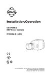
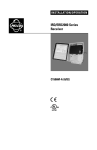
I N S TA L L AT I O N / O P E R AT I O N
®
Receiver for LWM41
Legacy® Series Mount
LRD41A11 Series
C553M-C (3/03)
CONTENTS
Section
Page
IMPORTANT SAFEGUARDS AND WARNINGS ................................................................................................................................................................. 3
DESCRIPTION .................................................................................................................................................................................................................... 3
MODELS ................................................................................................................................................................................................................... 3
INSTALLATION ...................................................................................................................................................................................................................
CABLE AND WIRING PREPARATION METHODS ......................................................................................................................................................
REAR ENTRY WITHOUT CONDUIT ..................................................................................................................................................................
REAR ENTRY WITH CONDUIT .........................................................................................................................................................................
BOTTOM ENTRY WITHOUT CONDUIT ............................................................................................................................................................
BOTTOM ENTRY WITH CONDUIT ...................................................................................................................................................................
INSTALLING THE SWITCH BRACKET .......................................................................................................................................................................
INSTALLING THE LRD41A11 SERIES RECEIVER .......................................................................................................................................................
CHANGING CAMERA VOLTAGE ...............................................................................................................................................................................
4
4
4
4
4
5
5
7
8
OPERATION ........................................................................................................................................................................................................................
CONTROL WITHOUT VIDEO .....................................................................................................................................................................................
TRANSIENT SUPPRESSION ......................................................................................................................................................................................
AUTO/RANDOM SCAN OPERATION ........................................................................................................................................................................
TEST LOCAL CONTROL (TLC) ....................................................................................................................................................................................
9
9
9
9
9
SPECIFICATIONS ................................................................................................................................................................................................................ 10
ELECTRICAL ..................................................................................................................................................................................................... 10
MECHANICAL .................................................................................................................................................................................................. 11
ENVIRONMENTAL ........................................................................................................................................................................................... 11
CERTIFICATIONS/RATINGS ............................................................................................................................................................................. 11
WARRANTY AND RETURN INFORMATION ...................................................................................................................................................................... 11
LIST OF ILLUSTRATIONS
Figure
1
2
3
4
5
6
2
Page
Switch Bracket Power Terminal Connections .................................................................................................................................................. 5
Installing Switch Bracket, Steps A and B ........................................................................................................................................................ 6
Installing Switch Bracket, Steps C and D ........................................................................................................................................................ 6
Installing the LRD41A11 Series Receiver ........................................................................................................................................................ 7
LRD41A11 Series Receiver Cable Connectors ................................................................................................................................................. 7
Camera Voltage Settings .................................................................................................................................................................................. 8
C553M-C (3/03)
IMPORTANT SAFEGUARDS AND WARNINGS
Prior to installation and use of this product, the following WARNINGS should be observed.
1.
Installation and servicing should be done only by qualified service personnel and conform to all local codes.
2.
Only use replacement parts recommended by Pelco.
3.
After replacement/repair of this unit’s electrical components, conduct a resistance measurement between line and
exposed parts to verify the exposed parts have not been connected to line circuitry.
The product and/or manual may bear the following marks:
This symbol indicates that dangerous voltage constituting a risk
of electric shock is present within this unit.
This symbol indicates that there are important operating and
maintenance instructions in the literature accompanying this unit.
CAUTION:
RISK OF ELECTRIC SHOCK.
DO NOT OPEN.
Please thoroughly familiarize yourself with the information in this manual prior to installation and operation.
DESCRIPTION
The LRD41A11 Series Legacy® system fixed speed receiver is designed for use with Pelco’s LWM41 wall mount. Standard
features include pan/tilt control, camera power, zoom lens control, wiper control, and scan capabilities.
MODELS
LRD41A11-1
LRD41A11-2
LRD41A11-3
C553M-C (3/03)
Legacy fixed speed receiver, 120 VAC input (FCC)
Same as LRD41A11-1 except 24 VAC input (CE, FCC)
Same as LRD41A11-1 except 230 VAC input (CE)
3
INSTALLATION
CABLE AND WIRING PREPARATION METHODS
There are four methods of installing the LWM41 wall mount. Cables can be fed directly into the rear of the LWM41 or through
the bottom of the mount arm. Conduit plates are supplied for added flexibility of installation. A rear entry, knock-off plate is
supplied with the mount arm and a bottom entry, gland/conduit plate is supplied with the LRD41A11 Series receiver.
Refer to one of the following sections to prepare wiring and cabling for your installation:
Rear Entry Without Conduit
Rear Entry With Conduit
Bottom Entry Without Conduit
Bottom Entry With Conduit
REAR ENTRY WITHOUT CONDUIT
1.
Pull the cabling into and through the rear entry of the LWM41 wall mount. Feed the power cable through the right side of
the mount and the video/auxiliary/alarm cables through the left side of the mount. Leave enough slack for connections,
preferably four to six inches.
2.
Install LWM41 wall mount (refer to the installation instructions supplied with the mount).
3.
Proceed to Installing the Switch Bracket.
REAR ENTRY WITH CONDUIT
1.
Secure the cable conduit to the block-off plate supplied with the LWM41 wall mount.
2.
Pull the cabling into and through the rear of the mount. Feed the power cable through the right side of the mount and the
video/auxiliary/alarm cables through the left side of the mount. Leave enough slack to make all connections (preferably
four to six inches).
3.
Install LWM41 wall mount (refer to the installation instructions supplied with the mount).
4.
Proceed to Installing the Switch Bracket.
BOTTOM ENTRY WITHOUT CONDUIT
4
1.
Install LWM41 wall mount (refer to the installation instructions supplied with the mount).
2.
Remove the bottom plate of the mount arm and replace with the gland/conduit plate provided with the LRD41A11 Series
receiver.
3.
Install the glands into the gland plate. Thread cabling/wiring through the glands. Do not install the BNC connector to the
video cable before threading the cable through the gland. The BNC connector will not fit through the PG-13 gland. Do not
use a gland sealing compound at this time.
4.
Feed the power cable through the right side of the mount and the video/auxiliary/alarm cables through the left side.
Leave adequate slack for connections.
5.
Tighten the glands and secure the gland/conduit plate to the bottom of the mount arm.
6.
Install the BNC connector to the video cable.
7.
Proceed to Installing the Switch Bracket.
C553M-C (3/03)
BOTTOM ENTRY WITH CONDUIT
1.
Install LWM41 wall mount (refer to the installation instructions supplied with the mount).
2.
Remove the bottom plate of the mount arm and replace with the gland/conduit plate provided with the LRD41A11 Series
receiver.
3.
Secure the conduit to the gland/conduit plate.
4.
Feed the power cable through the right side of the mount and the video/auxiliary/alarm cables through the left side.
Leave adequate slack for connections.
5.
Secure the gland/conduit plate to the bottom of the mount arm.
6.
Proceed to Installing the Switch Bracket.
INSTALLING THE SWITCH BRACKET
1.
Connect the power cable to the terminal block located on the bottom of the switch bracket (refer to Figure 1). Make sure
the ground is connected for 120 VAC and 230 VAC operation.
NOTE: If the cable cannot be retracted from the mount, push it into the cavity behind the hinge base.
Ground
Hot (High)
Neutral (Low)
Power in
Power input terminals for
120VAC, 230VAC, or 24VAC
Terminal ground for
120VAC or 230VAC
This set of terminals
factory set; not to be
adjusted by user.
Power switch
Securing Notches
NOTE: Power connector cable
to receiver/driver not shown.
Figure 1. Switch Bracket Power Terminal Connections
2.
C553M-C (3/03)
01280
Install the switch bracket inside the mount arm:
a.
Refer to Figure 2. Insert the notch on the right side of the switch bracket into the tab located in the back, right side
of the mount arm.
b.
Push up on the bracket to depress the bottom bow spring.
c.
Refer to Figure 3. Twist the left side of the bracket until the left notch clicks into place under the left tab.
d.
Make sure the tabs “click” into the securing notches of the bracket for a secure fit. You may have to pull the bracket
down into place.
5
01281
Figure 2. Installing Switch Bracket, Steps A and B
01282
Figure 3. Installing Switch Bracket, Steps C and D
6
C553M-C (3/03)
INSTALLING THE LRD41A11 SERIES RECEIVER
NOTE: The LRD41A1 Series receiver accommodates an additional electrical (coax) connection to the camera for camera synchronization, which is necessary when multiple cameras require frame synchronization.
The receiver box attaches to the inside access panel of the mount.
1.
Refer to Figure 4 and install the mounting hardware for the LRD41A11 Series receiver.
2.
Connect the video BNC and the switch bracket power connector to the rear of the receiver box.
NOTE: The power connector clicks and locks into place. After making the connection, move the power switch (located
inside the mount arm) to ON. Check the power LED on the receiver box for confirmation of power. Then turn off the switch.
3.
Mount the receiver box to the access panel by simply aligning the two mounting holes on the bottom of the receiver box
with the anchor and thumbnut hardware on the access panel (refer to Figure 4). After aligning the mounting holes/studs,
simply slide the receiver box down over the anchor and thumbnut and allow the box to attach securely.
4.
Tighten the locking thumbnut stud to secure the box in place. Make sure the thumbnut is very tight.
5.
Refer to Figure 5 and connect the Legacy 37-pin, pan/tilt connector to the receiver box.
Figure 4. Installing the LRD41A11 Series Receiver
Figure 5. LRD41A11 Series Receiver Cable Connectors
C553M-C (3/03)
7
CHANGING CAMERA VOLTAGE
Set the camera voltage jumpers for the voltage that the camera will use. Refer to Figure 6 for the locations and settings for the
jumpers.
WARNING: CAMERA DAMAGE POSSIBLE. You will damage your camera if you connect it to the wrong connector on an
EH4700L or EH5700L Series enclosure. If your camera will use the same power as the enclosure, plug the camera into the
CAM1 socket on the circuit board inside the enclosure. If your camera will use 24 VAC and the enclosure will use either 120
VAC or 230 VAC, plug the camera into the CAM2 socket only.
If your camera will use 24 VAC, do NOT plug the camera into the CAM1 socket or you will damage your camera. CAM1 has
either 120 VAC or 230 VAC on it.
BE CAREFUL – REMEMBER – CAM1 IS ENCLOSURE POWER. NEVER PLUG YOUR CAMERA INTO CAM1 IF THE
CAMERA’S VOLTAGE IS DIFFERENT FROM THE ENCLOSURE’S VOLTAGE.
Camera Voltage Settings
AC-HI
AC-LOW
COM
24 V
120 V
120 VAC Camera
Voltage for
LRD41A11-1
CAM-HI
CAM-LOW
PT-HI
PT-LOW
AC-HI
AC-LOW
COM
24 V
120 V
24 VAC Camera
Voltage for
LRD41A11-1, -2, -3
CAM-HI
PT-HI
PT-LOW
CAM-LOW
and
230 VAC Camera
Voltage for
LRD41A11-3
Jumper/Strap Location on PC Board
Potentiometer Adjustment For Lens Voltage
NOTE: Camera Strapping
wires are blue.
AC-HI
COM
AC-LOW
24 V
120 V
CAM-HI
PT-HI
CAM-LOW
PT-LOW
Increase
R65
Decrease
01278
Figure 6. Camera Voltage Settings
8
C553M-C (3/03)
OPERATION
CONTROL WITHOUT VIDEO
With this feature, the receiver can detect Coaxitron® commands from the controller when no video signal is present. Control
without video is mainly desired for the auxiliary function.
NOTE: The MPT9000, and the CM8500 and CM9500 families of controllers will transmit Coaxitron commands without reception
of video (composite sync) signal.
TRANSIENT SUPPRESSION
Transient suppression circuitry that has been designed into the LRD41A11-X receiver reduces the chance of interrupted
operation or damage to the receiver due to voltage spikes on the power and signal lines. Transient suppression does not imply
lightning suppression.
AUTO/RANDOM SCAN OPERATION
Depending on the type of control unit you have, auto and random scan can be operated in two ways:
•
•
Use the Auto/Man switch or keys (if your control unit has these functions)
Use presets
Auto/Man Switch – The random scan and auto scan functions are controlled by the same momentary switch on the control
panel labeled Auto and Man.
The first activation of the switch to the Auto position puts the pan/tilt into random scan. In random scan operation, the pan/tilt
travels between the preset limits with a random scan period of about 2 to 30 seconds, and a random dwell period of between 2
and 30 seconds. Following a dwell period, another random scan period starts. The direction of this scan period is also randomly
determined. When a pan limit is reached, scan direction reverses automatically.
A second activation of the Auto switch puts the pan/tilt into continuous duty auto scan (limit switch to limit switch). After
approximately 1/2 hour of auto scan, the circuit resets to random scan.
Subsequent operations of the Auto switch while in random scan mode cause a shift to auto scan mode and start the 1/2-hour
timer. Operating the Auto switch while in auto scan mode causes a shift to the random scan mode and zeros the 1/2-hour timer.
Presets – Auto and random scan also can be started by programming presets. The presets work only when your system is
configured for Extended (32-bit) Coaxitron mode.
Refer to your controller documentation for programming presets.
Preset 96 stops a scan.
Preset 97 starts random scan.
Preset 99 starts auto scan.
Advantages of random scan:
•
Because scan direction, scan period, and dwell period are unpredictable, unauthorized activities or intrusions are
discouraged.
•
Because of the reduced duty cycle, gear train wear, cable fatigue, drive motor wear, and temperature rise are reduced.
These factors all contribute to higher system reliability and increased equipment life.
TEST LOCAL CONTROL (TLC)
This feature allows you to connect an LRD41TLC test local control (TLC) module to the receiver to test the control of pan, tilt,
and lens functions locally. This is convenient for positioning limit stops, backfocusing, and troubleshooting the installation. The
TLC module also allows positioning of the camera locally.
To use the TLC module:
C553M-C (3/03)
1.
Plug the 16-pin connector from the TLC module into the TLC connector on the receiver (refer to Figure 5). You can plug in
the module when power for the receiver is turned on.
2.
Hold down the keys on the TLC module to operate the pan, tilt, and camera functions. The receiver does not have to be
connected to other control equipment in order for the TLC module to work. If the receiver is connected to other control
equipment, the TLC module will override any transmitter control signals from the other control equipment.
9
SPECIFICATIONS
ELECTRICAL
Input Voltage:
LRD41A11-1
Input Voltage:
P/T Voltage:
Camera Voltage:
Enclosure Voltage:
LRD41A11-2
Input Voltage:
P/T Voltage:
Camera Voltage:
Enclosure Voltage:
24 VAC
24 VAC
24 VAC
24 VAC
LRD41A11-3
Input Voltage:
P/T Voltage:
Camera Voltage:
Enclosure Voltage:
230 VAC
120 VAC
24 VAC or 230 VAC (selectable)
230 VAC
Frequency:
Power Consumption:
Video Input:
Video Output:
Video Bandwidth:
Video Gain:
Video Formats:
Control Method:
Lens Output
Voltage:
Current:
Operating Distances:
Cable Type
RG59/U
RG6/U
RG11/U
RG15
Fuse Values:
LRD41A11-1
LRD41A11-2
LRD41A11-3
10
120 VAC
120 VAC
24 VAC or 120 VAC (selectable)
120 VAC
60/50 Hz
5 VA
75 ohms terminating
75 ohms terminating
10 MHz
Unity
NTSC or PAL
Coaxitron, 15-bit protocol
6 VDC to 10 VDC
25 mA @ 10 VDC
100 mA @ 9 VDC
Cable distances are approximate according to cable type used. 75-ohm coax required.
Distance
750 ft
1,000 ft
1,500 ft
Distance Using EA2000
(229 m)
(305 m)
(457 m)
3,000 ft
4,500 ft
6,000 ft
8,000 ft
F1
LRD/PANTILT
2 amp
5 amp
1 amp
F2
ENCLOSURE
2 amp
6.3 amp
1 amp
—
(914 m)
(1,372 m)
(1,829 m)
(2,438 m)
C553M-C (3/03)
MECHANICAL
Case Dimensions:
11.5 (L) x 4.5 (W) x 2.75 (H) inches
(29.21 x 11.43 x 6.98 cm)
Alodine
BNC
37-pin CPC
Plastic, interlocking (female)
Finish:
Video Connectors:
Pan/Tilt Connector:
Power Connector:
Weight
Unit:
Shipping:
5 lb (2.27 kg)
6 lb (2.72 kg)
ENVIRONMENTAL
Operating
Temperature Range:
0°F to 120°F
(-17.7°C to 48.8°C)
CERTIFICATIONS/RATINGS
CE, Class A (LRD41A11-2 and LRD41A11-3)
FCC, Class A (LRD41A11-1 and LRD41A11-2)
Meets NEMA Type 4 standards when installed in LWM41 wall mount
WARRANTY AND RETURN INFORMATION
WARRANTY
Pelco will repair or replace, without charge, any merchandise proved defective in material or
workmanship for a period of one year after the date of shipment. Exceptions to this warranty are
as noted below:
• Five years on Pelco manufactured cameras (CC3500/CC3600/CC3700 and MC3500/
MC3600 Series); two years on all other cameras.
• Three years on Genex® Series (multiplexers, server, and keyboard) and 090 Series
Camclosure® Camera System.
• Two years on 100/150, 200 and 300 Series Camclosure® Camera Systems.
• Two years on all standard motorized or fixed focal length lenses.
• Two years on Legacy®, CM6700/CM6800/CM8500/CM9500/CM9740/CM9760 Matrix, DF5
and DF8 Series Fixed Dome products.
• Two years on Spectra®, Esprit®, and PS20 Scanners, including when used in continuous
motion applications.
• Two years on Esprit and WW5700 series window wiper (excluding wiper blades).
• Eighteen months on DX Series digital video recorders.
• One year (except video heads) on video cassette recorders (VCRs). Video heads will be
covered for a period of six months.
• Six months on all pan and tilts, scanners or preset lenses used in continuous motion
applications (that is, preset scan, tour and auto scan modes).
Pelco will warrant all replacement parts and repairs for 90 days from the date of Pelco
shipment. All goods requiring warranty repair shall be sent freight prepaid to Pelco, Clovis,
California. Repairs made necessary by reason of misuse, alteration, normal wear, or accident
are not covered under this warranty.
Pelco assumes no risk and shall be subject to no liability for damages or loss resulting from the
specific use or application made of the Products. Pelco’s liability for any claim, whether based on
breach of contract, negligence, infringement of any rights of any party or product liability, relating
to the Products shall not exceed the price paid by the Dealer to Pelco for such Products. In no
event will Pelco be liable for any special, incidental or consequential damages (including loss of
use, loss of profit and claims of third parties) however caused, whether by the negligence of
Pelco or otherwise.
The above warranty provides the Dealer with specific legal rights. The Dealer may also have
additional rights, which are subject to variation from state to state.
If a warranty repair is required, the Dealer must contact Pelco at (800) 289-9100 or (559) 292-1981 to
obtain a Repair Authorization number (RA), and provide the following information:
1. Model and serial number
2. Date of shipment, P.O. number, Sales Order number, or Pelco invoice number
3. Details of the defect or problem
If there is a dispute regarding the warranty of a product which does not fall under the warranty conditions
stated above, please include a written explanation with the product when returned.
Method of return shipment shall be the same or equal to the method by which the item was received by
Pelco.
RETURNS
In order to expedite parts returned to the factory for repair or credit, please call the factory at (800) 289-9100
or (559) 292-1981 to obtain an authorization number (CA number if returned for credit, and RA number if
returned for repair).
All merchandise returned for credit may be subject to a 20% restocking and refurbishing charge.
Goods returned for repair or credit should be clearly identified with the assigned CA or RA number and
freight should be prepaid. Ship to the appropriate address below.
If you are located within the continental U.S., Alaska, Hawaii or Puerto Rico:
Service Department
Pelco
3500 Pelco Way
Clovis, CA 93612-5699
If you are located outside the continental U.S., Alaska, Hawaii or Puerto Rico:
Intermediate Consignee
Ultimate Consignee
American Overseas Air Freight
Pelco
320 Beach Road
3500 Pelco Way
Burlingame, CA 94010
Clovis, CA 93612-5699
USA
USA
REVISION HISTORY
Manual #
C553M
C553M-A
C553M-B
C553M-C
Date
9/95
8/96
11/01
3/03
Comments
Original version.
Revised Sections 5.0 and 9.0, and changed the operating distances for coaxial cables in Section 10.0.
Revised manual to meet new design specifications. Updated manual to new format.
Revised figures 4 and 5 and the specifications to reflect the addition of a second fuse (ECO 03-8663).
® Pelco, the Pelco logo, Spectra, Genex, Legacy, Esprit and Camclosure are registered trademarks of Pelco.
C553M-C (3/03)
© Copyright 2003, Pelco. All rights reserved.
11
®
World Headquarters
3500 Pelco Way
Clovis, California 93612 USA
USA & Canada
Tel: 800/289-9100
Fax: 800/289-9150
International
Tel: 1-559/292-1981
Fax: 1-559/348-1120
www.pelco.com
ISO9001
Orangeburg, New York Las Vegas, Nevada Eindhoven, The Netherlands Wokingham, United Kingdom Montreal, Canada