1
Installation Guide
Network Camera
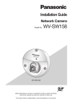
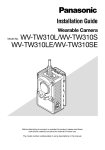
WV-SW316L/WV-SW316
WV-SW314
WV-SW316LE/WV-SW316E
Model No.
(This illustration represents WV-SW316.)
Before attempting to connect or operate this product, please read these
instructions carefully and save this manual for future use.
The model number is abbreviated in some descriptions in this manual.
For Europe
WARNING:
• To prevent injury, this apparatus must be
securely attached to the floor/wall/ceiling in
accordance with the installation instructions.
• The installation shall be carried out in accordance with all applicable installation rules.
• The connections should comply with local
electrical code.
Nosotros
declaramos
bajo
nuestra
única
responsabilidad que el producto a que hace referencia
esta declaración está conforme con la norma u otro
documento normativo siguiendo las estipulaciones de
la directiva 2004/108/CE.
UL listed model No.
WV-SW316L, WV-SW316, WV-SW314
For Canada
This Class A digital apparatus complies with
Canadian ICES-003.
For U.S.A
NOTE: This equipment has been tested and
found to comply with the limits for a Class A digital device, pursuant to Part 15 of the FCC Rules.
These limits are designed to provide reasonable
protection against harmful interference when the
equipment is operated in a commercial environment. This equipment generates, uses, and can
radiate radio frequency energy and, if not installed
and used in accordance with the instruction manual, may cause harmful interference to radio communications.
Operation of this equipment in a residential area
is likely to cause harmful interference in which
case the user will be required to correct the interference at his own expense.
FCC Caution: To assure continued compliance,
(example - use only shielded interface cables
when connecting to computer or peripheral
devices). Any changes or modifications not
expressly approved by the party responsible for
compliance could void the user’s authority to
operate this equipment.
For U.S.A
The model number and serial number of this
product may be found on the surface of the unit.
You should note the model number and serial
number of this unit in the space provided and
retain this book as a permanent record of your
purchase to aid identification in the event of
theft.
2
Wir erklären in alleiniger Verantwortung, daß das
Produkt, auf das sich diese Erklärung bezieht, mit der
folgenden
Norm
oder
normativen
Dokument
übereinstimmt. Gemäß den Bestimmungen der
Richtlinie 2004/108/EC.
Nous déclarons sous notre propre responsabilité que le
produit auquel se réfère la présente déclaration est
conforme á la norme spécifiée ou à tout autre
document normatif conformément aux dispositions de
la directive 2004/108/CE.
For U.S. and Canada:
WV-SW316L, WV-SW316, WV-SW314
For Europe and other countries:
WV-SW316LE, WV-SW316E
Model No.
Serial No.
We declare under our sole responsibility that the
product to which this declaration relates is in
conformity with the standard or other normative
document following the provisions of Directive
2004/108/EC.
Noi dichiariamo sotto nostra esclusiva responsabilità
che il prodotto a cui si riferisce la presente
dichiarazione risulta conforme al seguente standard o
altro documento normativo conforme alle disposizioni
della direttiva 2004/108/CE.
Wij verklaren als enige aansprakelijke, dat het product
waarop deze verklaring betrekking heeft, voldoet aan
de volgende norm of ander normatief dokument,
overeenkomstig de bepalingen van Richtlijn 2004/108/
EC.
Vi erklærer os eneansvarlige for, at dette produkt, som
denne deklaration omhandler, er i overensstemmelse
med standard eller andre normative dokumenter i følge
bestemmelserne i direktiv 2004/108/EC.
Vi deklarerar härmed vårt fulla ansvar för att den
produkt till vilken denna deklaration hänvisar är i
överensstämmelse med standarddokument eller annat
normativt dokument som framställs i direktiv 2004/108/
EC.
Ilmoitamme yksinomaisella vastuullamme, että tuote,
jota tämä ilmoitus koskee, noudattaa seuraavaa
standardia tai muuta ohjeellista asiakirjaa, jotka
noudattavat direktiivin 2004/108/EC säädöksiä.
Vi erklærer oss alene ansvarlige for at produktet som
denne erklæringen gjelder for, er i overensstemmelse
med følgende norm eller andre normgivende
dokumenter som følger bestemmelsene i direktiv
2004/108/EC.
Contents
Important safety instructions.......................................................................................................... 4
Limitation of liability........................................................................................................................ 5
Disclaimer of warranty.................................................................................................................... 5
Preface........................................................................................................................................... 5
About notations.............................................................................................................................. 6
Main functions................................................................................................................................ 6
About the user manuals................................................................................................................. 7
System requirements for a PC....................................................................................................... 7
Trademarks and registered trademarks......................................................................................... 8
Copyright........................................................................................................................................ 8
Network security............................................................................................................................ 9
Precautions.................................................................................................................................. 10
Precautions for installation........................................................................................................... 14
Major operating controls.............................................................................................................. 16
Preparations................................................................................................................................. 19
Installations / Connections........................................................................................................... 20
Insert/remove an SDHC/SD memory card (WV-SW316L/WV-SW316 Only)................................ 28
Adjustment................................................................................................................................... 29
Mounting the front cover.............................................................................................................. 33
Attaching the mounting surface on the top surface of the camera body.................................... 34
Using the CD-ROM...................................................................................................................... 37
Configure the network settings.................................................................................................... 40
Troubleshooting............................................................................................................................ 42
Specifications............................................................................................................................... 43
Standard accessories................................................................................................................... 48
Optional accessories.................................................................................................................... 48
3
Important safety instructions
1) Read these instructions.
2) Keep these instructions.
3) Heed all warnings.
4) Follow all instructions.
5) Do not block any ventilation openings. Install in accordance with the manufacturer's instructions.
6) Do not install near any heat sources such as radiators, heat registers, stoves, or other apparatus (including amplifiers) that produce heat.
7) Only use attachments/accessories specified by the manufacturer.
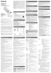
8) Use only with the cart, stand, tripod, bracket, or table specified by the manufacturer, or sold
with the apparatus. When a cart is used, use caution when moving the cart/apparatus combination to avoid injury from tip-over.
S3125A
9) Unplug this apparatus during lightning storms or when unused for long periods of time.
10) Refer all servicing to qualified service personnel. Servicing is required when the apparatus has
been damaged in any way, such as power-supply cord or plug is damaged, liquid has been
spilled or objects have fallen into the apparatus, the apparatus has been exposed to rain or
moisture, does not operate normally, or has been dropped.
4
Limitation of liability
THIS PUBLICATION IS PROVIDED "AS IS" WITHOUT WARRANTY OF ANY KIND, EITHER
EXPRESS OR IMPLIED, INCLUDING BUT NOT LIMITED TO, THE IMPLIED WARRANTIES OF
MERCHANTABILITY, FITNESS FOR ANY PARTICULAR PURPOSE, OR NON-INFRINGEMENT OF
THE THIRD PARTY'S RIGHT.
THIS PUBLICATION COULD INCLUDE TECHNICAL INACCURACIES OR TYPOGRAPHICAL
ERRORS. CHANGES ARE ADDED TO THE INFORMATION HEREIN, AT ANY TIME, FOR THE
IMPROVEMENTS OF THIS PUBLICATION AND/OR THE CORRESPONDING PRODUCT (S).
Disclaimer of warranty
IN NO EVENT SHALL Panasonic System Networks Co., Ltd. BE LIABLE TO ANY PARTY OR ANY
PERSON, EXCEPT FOR REPLACEMENT OR REASONABLE MAINTENANCE OF THE PRODUCT,
FOR THE CASES, INCLUDING BUT NOT LIMITED TO BELOW:
(1) ANY DAMAGE AND LOSS, INCLUDING WITHOUT LIMITATION, DIRECT OR INDIRECT,
SPECIAL, CONSEQUENTIAL OR EXEMPLARY, ARISING OUT OF OR RELATING TO THE
PRODUCT;
(2) PERSONAL INJURY OR ANY DAMAGE CAUSED BY INAPPROPRIATE USE OR NEGLIGENT
OPERATION OF THE USER;
(3) ALL MALFUNCTIONS OR TROUBLES FROM UNAUTHORIZED DISASSEMBLE, REPAIR OR
MODIFICATION OF THE PRODUCT BY THE USER, REGARDLESS OF THE CAUSE OF THE
MALFUNCTION OR TROUBLE;
(4) INCONVENIENCE OR ANY LOSS ARISING WHEN IMAGES ARE NOT DISPLAYED, DUE TO
ANY REASON OR CAUSE INCLUDING ANY FAILURE OR PROBLEM OF THE PRODUCT;
(5) ANY PROBLEM, CONSEQUENTIAL INCONVENIENCE, OR LOSS OR DAMAGE, ARISING
OUT OF THE SYSTEM COMBINED BY THE DEVICES OF THIRD PARTY;
(6) ANY CLAIM OR ACTION FOR DAMAGES, BROUGHT BY ANY PERSON OR ORGANIZATION
BEING A PHOTOGENIC SUBJECT, DUE TO VIOLATION OF PRIVACY WITH THE RESULT OF
THAT SURVEILLANCE-CAMERA'S PICTURE, INCLUDING SAVED DATA, FOR SOME
REASON, BECOMES PUBLIC OR IS USED FOR ANY PURPOSE;
(7) LOSS OF REGISTERED DATA CAUSED BY ANY FAILURE.
Preface
The network camera WV-SW316L/WV-SW316/WV-SW314 is designed to operate using a PC on a
network (10BASE-T/100BASE-TX), and can be installed outdoors.
By connecting to a network (LAN) or the Internet, images and audio from the camera can be monitored on a PC via a network.
Note:
• It is necessary to configure the network settings of the PC and its network environment to
monitor images from the camera on the PC. It is also necessary to install a web browser on the
PC.
5
About notations
The following notations are used when describing the functions limited for specified models. The
functions without the notations are supported by all models.
SW316L : The functions with this notation are available when using the model WV-SW316L.
SW316 : The functions with this notation are available when using the model WV-SW316.
SW314 : The functions with this notation are available when using the model WV-SW314.
Main functions
Super Dynamic
(☞ Operating Instructions (included in the CD-ROM))
Super Dynamic compensates brightness on a pixel-to-pixel basis so that it produces clearer images
even if objects have various illumination intensities.
H.264/MPEG-4 and JPEG triple encoding
H.264/MPEG-4 dual stream output and JPEG (MJPEG) output can be simultaneously provided.
* Either H.264 or MPEG-4 is selectable.
SW316
Auto focus (AF) function SW316L
It is possible to adjust the focus automatically by moving the focus ring of the lens with the operation button of this camera or the setup menu.
SW316
Black & white mode SW316L
Images will be displayed clear even at night since the camera will be automatically switched from
the color mode to the black and white mode under low illumination condition.
SW316
Motorized varifocal lens equipped SW316L
The zoom ratio can be changed and adjusted to an optional photographic area through the operation buttons on this unit and the setup menu.
IR LED equipped SW316L
The equipped infrared LED makes it possible to take pictures at zero lx.
Power over Ethernet function
When connecting with a PoE (Power over Ethernet) device, power will be supplied by simply connecting a LAN cable. (IEEE802.3af compliant)
SW316
Interactive communication with audio SW316L
By using the audio output connector and the microphone in connector, receiving audio from the
cameras on a PC and transmitting audio from the PC to the cameras is available.
SW316
SDHC/SD memory card slot equipped SW316L
It is possible to save H.264 videos and JPEG images on the SDHC/SD memory card manually at
an alarm occurrence, during the period of the schedule, or on a web browser. It is also possible to
save JPEG images at a network failure occurrence. (Download is possible.)
(Recommended SDHC/SD memory card ☞ page 47)
6
About the user manuals
There are 2 sets of operating instructions for the WV-SW316L, WV-SW316, WV-SW314 (P model),
WV-SW316LE, WV-SW316E (E model) as follows.
• InstallationGuide:Explainshowtoinstallandconnectdevices.
• Operating Instructions (included in the CD-ROM): Explains how to perform the settings and
how to operate this camera.
Adobe® Reader® is required to read these operating instructions on the provided CD-ROM.
When the Adobe Reader is not installed on the PC, download the latest Adobe Reader from the
Adobe web site and install it.
"WV-SW316L, WV-SW316, WV-SW314" or "SW316L, SW316, SW314" shown in the instructions
and illustrations used in these operating instructions indicates the WV-SW316L, WV-SW316,
WV-SW314, WV-SW316LE, WV-SW316E.
The screens used in these operating instructions show the cases of P models.
System requirements for a PC
CPU:
Memory:
Network interface:
Audio interface:
Monitor:
OS:
Web browser:
Others:
Intel® CoreTM 2 Duo 2.4 GHz or faster recommended
512 MB or more (A minimum of 1 GB memory is required when using
Microsoft® Windows® 7 or Microsoft® Windows Vista®.)
10BASE-T/100BASE-TX 1 port
Sound card (when using the audio function)
Image capture size: 1024 x 768 pixels or more
Color: 24-bit True color or better
Microsoft® Windows® 7
Microsoft® Windows Vista®
Microsoft® Windows® XP SP3
Windows® Internet Explorer® 9.0 (32-bit)
Windows® Internet Explorer® 8.0 (32-bit)
Windows® Internet Explorer® 7.0 (32-bit)
Microsoft® Internet Explorer® 6.0 SP3
CD-ROM drive
(It is necessary to read the operating instructions and use the software on
the provided CD-ROM.)
DirectX® 9.0c or later
Adobe® Reader®
(It is necessary to view the PDF file on the provided CD-ROM.)
7
IMPORTANT:
• When using a PC that does not meet the above requirements, displaying of images may
become slower or the web browser may become inoperable.
• Microsoft Windows 7 Starter, Microsoft Windows Vista Starter and Microsoft Windows XP
Professional 64-bit Edition are not supported.
• WhenusingIPv6forcommunication,useMicrosoftWindows7orMicrosoftWindowsVista.
Note:
• For further information about PC system requirements and precautions for when using
Microsoft Windows 7, Microsoft Windows Vista, or Windows Internet Explorer, click "Manual" "Open" from the supplied CD-ROM and refer to "Notes on Windows® / Internet Explorer®
versions".
• IfusingMicrosoftWindowsXP,screentearing*mayoccurwhentheshootingscenedrastically
changes (for example, while shooting fast-moving subjects) due to the GDI restrictions of the
OS.
* A phenomenon in which portions of the screen are displayed out of alignment
• For information on the operation verification of the supported operating systems and web
browsers, refer to our website at http://panasonic.net/pss/security/support/index.html.
Trademarks and registered trademarks
• Adobe,theAdobelogo,andReaderareeitherregisteredtrademarksortrademarksofAdobe
Systems Incorporated in the United States and/or other countries.
• Microsoft, Windows, Windows Vista, Internet Explorer, ActiveX, and DirectX are either registered trademarks or trademarks of Microsoft Corporation in the United States and/or other
countries.
• Microsoftproductscreenshot(s)reprintedwithpermissionfromMicrosoftCorporation.
• IntelandIntelCorearetrademarksorregisteredtrademarksofIntelCorporationoritssubsidiaries in the United States and other countries.
• SDHCLogoisatrademarkofSD-3C,LLC.
• iPad, iPhone, and iPod touch are trademarks of Apple Inc., registered in the U.S. and other
countries.
• AndroidisatrademarkofGoogleInc.UseofthistrademarkissubjecttoGooglePermissions.
• Allothertrademarksidentifiedhereinarethepropertyoftheirrespectiveowners.
Copyright
Distributing, copying, disassembling, reverse compiling and reverse engineering of the software
provided with this product are all expressly prohibited. In addition, exporting any software provided
with this product violating export laws is prohibited.
8
Network security
As you will use this unit connected to a network, your attention is called to the following security
risks.
q Leakage or theft of information through this unit
w Use of this unit for illegal operations by persons with malicious intent
e Interference with or stoppage of this unit by persons with malicious intent
It is your responsibility to take precautions such as those described below to protect yourself
against the above network security risks.
• Usethisunitinanetworksecuredbyafirewall,etc.
• IfthisunitisconnectedtoanetworkthatincludesPCs,makesurethatthesystemisnotinfected by computer viruses or other malicious entities (using a regularly updated anti-virus program, anti-spyware program, etc.).
• Protectyournetworkagainstunauthorizedaccessbyrestrictinguserstothosewhologinwith
an authorized user name and password.
• Applymeasuressuchasuserauthenticationtoprotectyournetworkagainstleakageortheftof
information, including image data, authentication information (user names and passwords),
alarm mail information, FTP server information and DDNS server information.
• Aftertheunitisaccessedbytheadministrator,makesuretoclosethebrowser.
• Changetheadministratorpasswordperiodically.
• Do not install the camera in locations where the camera or the cables can be destroyed or
damaged by persons with malicious intent.
9
Precautions
Refer installation work to the dealer.
Installation work requires technique and experiences. Failure to observe this may cause fire,
electric shock, injury, or damage to this product.
Be sure to consult the dealer.
Stop the operation immediately when
something is wrong with this product.
When smoke goes up from the product, the
smell of smoke comes from the product, or the
exterior of the product has deteriorated, continued use will cause a fire or fall of the product
resulting in injury, accidents, or damage to the
product.
Turn the power off immediately and contact
qualified service personnel for service.
Do not attempt to disassemble or modify
this product.
Failure to observe this may cause fire or electric
shock.
Consult the dealer for the repair or inspections.
Do not insert any foreign objects.
This could permanently damage this product.
Turn the power off immediately and contact
qualified service personnel for service.
Select an installation area that can support the total weight.
Selecting an inappropriate installation surface
may cause this product to fall down or topple
over, resulting in injury.
Installation work shall be started after sufficient
reinforcement.
Periodic inspections shall be conducted.
Rust on the metal parts or screws may cause a
fall of the product resulting in injury or accidents.
Consult the dealer for the inspections.
Do not use this product in an inflammable
atmosphere.
Failure to observe this may cause an explosion
resulting in injury.
10
Avoid installing this bracket in the locations where salt damage occurs or corrosive gas is produced.
Otherwise, the mounting portions will deteriorate and accidents such as a fall of the product
may occur.
Do not install this product in locations
subject to vibration.
Loosening of mounting screws or bolts may
cause a fall of the product resulting in injury.
Install this product in a location high
enough to avoid people and objects from
bumping the product.
Failure to observe this may cause a drop resulting in injury or accidents.
Do not strike or give a strong shock to this
product.
Failure to observe this may cause fire or injury.
Turn the power off when do wiring of this
product.
Failure to observe this may cause electric
shock. In addition, short circuit or wrong wiring
may cause fire.
The exclusively designed mount bracket
shall be used.
Failure to observe this may cause a drop resulting in injury or accidents.
Use the exclusively designed mount bracket for
installation.
The screws and bolts must be tightened to
the specified torque.
Failure to observe this may cause a drop resulting in injury or accidents.
Do not rub the edges of metal parts with
your hand.
Failure to observe this may cause injury.
Do not touch this product, the power cord
or the connected cables during thunder.
(even in the process of work)
Failure to observe this may cause electric shock.
Keep SDHC/SD memory cards (option)
away from infants and children. SW316L
To keep on using with stable performance
Do not use this product in hot and humid conditions for a long time. Failure to observe this
causes component degradation resulting in life
shortening of this product.
Do not expose the product to direct heat
sources such as a heater.
SW316
Otherwise, they may swallow the cards by mistake.
In this case, consult a doctor immediately.
Do not touch the front cover with your
bare hands.
A dirty cover causes deterioration of picture quality.
The measures of protection against snowfall shall be taken.
In areas where lots of snow accumulates, the
weight of snow may cause the product to fall
resulting in injury or accidents. Protect the
product against snowfall by installing under
eaves.
Handle this product with care.
Do not drop this product, nor apply shock or
vibration to the product. Failure to observe this
may cause trouble. If a strong shock or vibration is applied to the front cover, it may cause
damage or allow water to enter this product.
The screws and fixed parts must be
securely tightened.
Failure to observe this may cause the product
to fall resulting in injury.
The measures of protection against a fall
of this product shall be taken.
Failure to observe this may cause a drop resulting in injury or accidents.
Do not damage the power cable.
SW316L
SW316
Do not damage, fabricate, twist, stretch, bundle, or forcibly bend the power cable. Do not
place heavy objects.
Keep away from heat sources.
Use of the damaged power cable may cause
electric shock, short circuit, or fire.
Consult the dealer for repair.
Turn the power off when cleaning this product.
Failure to observe this may cause injury.
[Precautions for use]
This product has no power switch.
When turning off the power, disconnect the
power supply from the 12 V DC power supply or
the PoE device. (When using both the 12 V DC
power supply and the PoE device for power
supply, disconnect both the connections.)
About the PC monitor
Displaying the same image on a monitor for a
long time may damage the monitor. It is recommended to use a screen-saver.
Product disposal/transfer
Data saved on this product or a storage device
used with this product may lead to personal
information leakage.
When it is necessary to dispose or give this
product to someone, even when for repair, make
sure that there is no data on this product.
Cleaning this product body
Be sure to turn off the power before cleaning.
Failure to observe this may cause injury. Do not
use strong abrasive detergent when cleaning
this product. Otherwise, it may cause discoloration. When using a chemical cloth for cleaning, read the caution provided with the chemical cloth product.
Cleaning the lens
Use a lens cleaning paper (used to clean camera lenses or lenses of spectacles). When using
solvent, use an alcohols solvent and do not use
a thinner or a glass cleaner.
11
Transmission interval
Image transmission interval may become slow
depending on the network environment, PC
performance, shooting subject, access number, etc.
About SDHC/SD memory card
SW316L
SW316
• Before inserting the SDHC/SD memory
card, turn off the power of this product
first. Otherwise, it may cause malfunction
or damage data recorded on the SDHC/
SD memory card. Refer to page 28 for
descriptions of how to insert/remove an
SDHC/SD memory card.
• WhenusingaSDHC/SDmemorycard,format it using this product. Recorded data
on the SDHC/SD memory card will be
deleted when formatted. If an unformatted
SDHC/SD memory card or a SDHC/SD
memory card formatted with other devices
is used, this product may not work properly or performance deterioration may be
caused. Refer to the Operating Instructions
(included in the CD-ROM) for how to format a SDHC/SD memory card.
• When some SDHC/SD memory cards are
used with this product, the product may
not work properly or performance deterioration may be caused. Use the SDHC/SD
memory cards recommended in page 47.
Code label
The code labels (accessory) are required at
inquiry for trouble. Use caution not to lose
these labels. It is recommended to paste one
of the labels onto the CD-ROM case.
12
Discoloration on the color filter of the
MOS image sensor
• When continuously shooting a bright light
source such as a spotlight, the color filter
of the MOS image sensor may have deteriorated and it may cause discoloration.
Even when changing the fixed shooting
direction after continuously shooting a
spotlight for a certain period, the discoloration may remain.
• Whenshootingfast-movingsubjectsor
performing panning/tilting operations,
objects crossing the shooting area may
look to be bending askew.
MPEG-4 Visual Patent Portfolio License
This product is licensed under the MPEG-4
Visual Patent Portfolio License for the personal
and non-commercial use of a consumer for (i)
encoding video in compliance with the MPEG4 Visual Standard ("MPEG-4 Video") and/or (ii)
decoding MPEG-4 Video that was encoded by
a consumer engaged in a personal and noncommercial activity and/or was obtained from
a video provider licensed by MPEG LA to
provide MPEG-4 Video. No license is granted
or shall be implied for any other use. Additional
information including that relating to
promotional, internal and commercial uses and
licensing may be obtained from MPEG LA,
LLC.
See http://www.mpegla.com.
AVC Patent Portfolio License
THIS PRODUCT IS LICENSED UNDER THE
AVC PATENT PORTFOLIO LICENSE FOR THE
PERSONAL USE OF A CONSUMER OR
OTHER USES IN WHICH IT DOES NOT
RECEIVE REMUNERATION TO (i) ENCODE
VIDEO IN COMPLIANCE WITH THE AVC
STANDARD ("AVC VIDEO") AND/OR (ii)
DECODE AVC VIDEO THAT WAS ENCODED
BY A CONSUMER ENGAGED IN A
PERSONAL ACTIVITY AND/OR WAS
OBTAINED FROM A VIDEO PROVIDER
LICENSED TO PROVIDE AVC VIDEO. NO
LICENSE IS GRANTED OR SHALL BE
IMPLIED FOR ANY OTHER USE. ADDITIONAL
INFORMATION MAY BE OBTAINED FROM
MPEG LA, L.L.C.
SEE HTTP://WWW.MPEGLA.COM
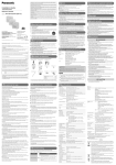
About the dehumidifying device
SW316L
SW316
• This product has dehumidifying device to
keep the inside at low moisture level, preventing condensation and quickly dissipating dew if produced.
• Dew may be produced depending on the
conditions of temperature, humidity, winds,
and rain, and it may take time to dehumidify.
• Neversealthesurfacesofthedehumidifying device.
Dehumidifying device
13
Precautions for installation
Panasonic assumes no responsibility for injuries or property damage resulting from failures arising out of improper installation or operation inconsistent with this documentation.
Installing place
Contact your dealer for assistance if you are
unsure of an appropriate place in your particular environment.
• Make sure that the installation area is
strong enough to hold this product, such
as a concrete ceiling.
• Installthecamerainthefoundationareaof
the architecture or where sufficient strength
is assured.
• If a wall or ceiling board such as plaster
board is too weak to support the total
weight, the area shall be sufficiently reinforced.
Do not place this product in the following
places:
• Locationswhereachemicalagentisused
such as a swimming pool
• Locations subject to oil smoke such as a
kitchen
• Locationsthathaveaspecificenvironment
that is subject to an inflammable atmosphere or solvents
• Locations where a radiation, an X-ray, a
strong radio wave or a strong magnetic
field is generated
• Locations where corrosive gas is produced, locations where it may be damaged
by briny air such as seashores
• Locations where the temperature is not
within the specified range (page 43).
• Locationssubjecttovibrations(Thisproduct is not designed for on-vehicle use.)
Be sure to remove this product if it is not
in use.
14
Design and engineer the power supply
system to turn on/off the power of this
product.
The product has no power switch. When
installing the product, use a power supply
device equipped with the ON-OFF switch for
servicing.
About the network connection
When connecting to a network using the network
cable of this product, observe the following.
• When wiring for the network, design and
engineer not to be affected by thunder.
• It is impossible to install this product in
combination with a pan/tilt head.
Screw tightening
• The screws and bolts must be tightened
with an appropriate tightening torque
according to the material and strength of
the installation area.
• Do not use an impact driver. Use of an
impact driver may damage the screws or
cause tightening excessively.
• Tightenscrewsatarightangletothesurface. After tightening screws, perform visual check to ensure tightening is so sufficient that there is no backlash.
The measures of protection against a fall
of this product shall be taken.
Failure to observe this may cause a drop resulting
in injury or accidents. Be sure to install the safety
wire.
Procure fixing screws separately.
The screws that secure this product are not
supplied. Prepare them according to the material and strength of the area where the product
is to be installed.
Radio disturbance
When this product is used near TV/radio antenna, strong electric field or magnetic field (near a
motor, a transformer or a power line), images
may be distorted and noise sound may be produced.
Time & date setting
It is necessary to set the time & date before
putting this product into operation. Refer to the
Operating Instructions on the provided
CD-ROM for descriptions of how to perform
the settings.
Take notice of humidity.
Install this product when the humidity is low. If
this product is installed during rainfall or at a
high humidity, the inside may be exposed to
moisture and the front cover may become
foggy.
Heater unit
This product is equipped with an internal heater
unit for use in cold climates. The heater unit turns
on automatically when the temperature inside the
product drops below 0 °C {32 °F}. However, in
an extremely low-temperature environment below
–30 °C {–22 °F}, snow and frost may not be
defrosted from the front cover. When using the
product in cold climates, take notice of the ambient and internal temperatures of the product.
When this product is installed and operated in
low temperatures below –10 °C {14 °F}, normal
images may not be obtained immediately after
startup. In such a case, wait around 2 hours or
more, and turn on the power again.
PoE (Power over Ethernet)
Use a PoE hub/device that is compliant with
IEEE802.3af standard.
Router
When connecting this product to the Internet,
use a broadband router with the port forwarding function (NAT, IP masquerade).
Refer to the Operating Instructions (included in
the CD-ROM) for further information about the
port forwarding function.
15
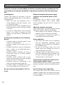
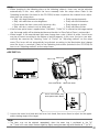
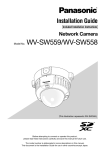
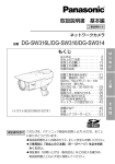
Major operating controls
Rear part of sunshield
Sunshield
Front cover
Rear cover
Focus ring
Tilting table
Zoom lock knob
Safety wire
TO
P
Zoom ring
Tilting lock screw (x2)
M
A
TR AL
R
EX C M
TO T
F/ PTI O
NI U
O O AL A O ZO
I
IT ET
IN S
Azimuth
adjustment ring
Tilting lock screw
Panning lock screw
SD CHEATE
A R
/ AFRD
(This illustration represents WV-SW316.)
Network cable
RJ-45 (female)
Alarm input/output cable
Power cable (12 V DC)
Microphone/line input cable (white)
Audio output cable (black)
Camera mount bracket
(accessory)
16
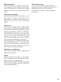
Mount bracket cover x2
(accessories)
(This illustration represents WV-SW316.)
SD memory card error indicator/
Auto focus indicator
(blinks when adjusting auto focus)
Access indicator (lit when accessing)
Link indicator (lit when linking)
SDHC/SD memory card slot
Auto focus (AF) button
TELE button
Initial set button
WIDE button
WV-SW316L/WV-SW316
Access indicator (lit when accessing)
Link indicator (lit when linking)
Focus assist (F.A.) button/
Extra optical zoom button
Initial set button
WV-SW314
17
WV-SW316L
WV-SW316
IR LED
Lens
Lens cover
Packing
Monitor output jack
WV-SW314
Lens
Focus lock knob
Desiccant attachment position
Monitor output jack
18
Zoom lock knob
Packing
Lens cover
Preparations
Caution:
• FORULLISTEDMODEL(S),ONLYCONNECT12VDCCLASS2POWERSUPPLY.
• Thecameramountbracketcanbedirectlymountedonthewallusingajunctionbox(locally
procured) embedded in the wall, or a wall with a cable access hole.
• Thescrewsthatsecurethecameramountbracketonawallarenotsupplied.Preparethe
screws according to the material, structure, strength and other factors of the mounting area
and the total weight of objects to be mounted.
IMPORTANT:
• Preparethemountingscrewsaccordingtothematerialoftheareawherethecameramount
bracket and the adapter box are to be installed. In this case, wood screws and nails should not
be used. Recommended tightening torque M4: 1.57 N·m {1.16 lbf·ft}
• Requiredpull-outcapacityofasinglescrew/boltis196N{44.06lbf}ormore.
• Ifawallorceilingboardsuchasplasterboardistooweaktosupportthetotalweight,thearea
shall be sufficiently reinforced.
19
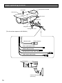
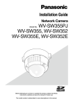
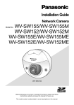
Installations / Connections
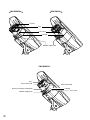
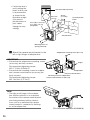
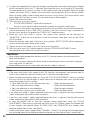
Secure the camera to the camera mount bracket
The tilt angle is locked downward at shipment.
z Loosen the tilting lock screw approx. 1 rotation and adjust the tilt angle of the camera to the
horizontal position.
x Tighten the tilting lock screw again after tilt angle adjustment.
Note:
• Useahexagonalwrenchwithwidthacrossflatsof4mm(locallyprocured)toloosenortighten
the tilting lock screw.
Tilting lock screw
Horizontal
Camera main body
Approx. 90°
(This illustration represents WV-SW316.)
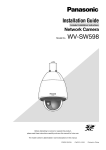
c Pass each cable and the safety wire through the camera mount bracket, and secure the camera to the camera mount bracket with the camera fixing screws x3 (accessory).
Pass the network cable first through the camera mount bracket before passing through the
other cables.
IMPORTANT:
• Ensurethatthecamerafixingscrews(accessory)arefirmlysecured.
Recommended tightening torque: 0.78 N·m {0.58 lbf·ft}
Camera main body
Mounting boss for safety wire
Video output cable
Safety wire
Network cable
Camera fixing screw x3 (M4 x 8)
(accessories)
Drain slit
Cable clamp
Camera mount bracket
(This illustration represents WV-SW316.)
20
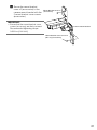
Camera mount bracket
v Remove the screws from the mounting boss of the safety wire and the mounting boss of the
cable clamp.
b Secure the safety wire with the screw from the mounting boss. Then, bundle the wire and the cable
using the cable clamp and secure them with each screw from the mounting boss as illustrated.
IMPORTANT:
• Ensure that the safety wire is firmly secured.
Recommended tightening torque: 0.59 N·m {0.44 lbf·ft}
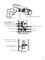
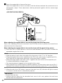
Connection
Caution:
• FORULLISTEDMODEL(S),ONLYCONNECT12VDCCLASS2POWERSUPPLY.
Turn off a circuit breaker before making a connection. Before starting the connection, prepare the
required devices and cables.
LAN cable
(category 5 or better, straight, STP*)
Network cable
RJ-45 (female)
Alarm input/output cable
4P alarm cable (accessory)
Power cable
(12 V DC)
2P power cable
(accessory)
12 V DC (red)
GND (black)
Microphone/line input cable (white)
Audio output cable (black)
(This illustration represents WV-SW316.)
<Required cable>
LAN cable (category 5 or better, straight, STP*)
* E model only
z Connect the microphone/line input cable and the microphone (for use of the audio reception
SW316
function). SW316L
Input impedance:
2 kΩ±10 %
Recommended cable length: Less than 1 m {3.28'} (for microphone input)
Less than 10 m {32.8'} (for line input)
Recommended microphone: Plug-in power type microphone (option)
Connect a mini plug (ø3.5 mm).
Supply voltage:
2.5 V ±0.5 V
Recommended sensitivity of microphone: −48 dB ±3 dB (0 dB=1 V/Pa,1 kHz)
IMPORTANT:
• Connect/disconnect the external speaker cables or audio/video cables after turning off the
power of the camera and the amplifier. Otherwise, loud noise may come out from the speaker.
x Connect
an external amplifier-embedded speaker to the audio output cable (for use of the
SW316
audio transmission function). SW316L
Connect a stereo mini plug (ø3.5 mm) (Audio output is monaural.).
• Recommendedcablelength:Lessthan10m{32.8ft}
21
c Connect the alarm input/output cable.
SW316L
SW316
<Ratings>
Terminal name
Ratings
ALARM OUT, AUX OUT
Open collector output (maximum applied voltage: 20 V DC)
Open
4 V DC - 5 V DC by internal pull-up
Close
Output voltage 1 V DC or less (50 mA or less)
ALARM IN, DAY/NIGHT IN Non-voltage make contact input (4 V DC - 5 V DC, internally pulled
up)
OFF
Open or 4 V DC - 5 V DC
ON
Make contact with GND (required drive current: 1 mA or more)
Note:
• Checkifratingofanexternaldevicesuchasasensorisapplicabletotheratingofthisproduct
by referring to the provided operating instructions.
Specification of 4P alarm cable (accessory)
GND (black)
AUX OUT (gray) (Terminal 3)
ALARM OUT (red) (Terminal 2)
ALARM IN, DAY/NIGHT IN (green) (Terminal 1)
v Connect a LAN cable (category 5e or better, straight, STP*) to the network connector.
* E model only
b Connect the power cable.
SW316
• Whenusing12VDCpowersupply*1 SW316L
Connect the output cable of the AC adaptor to the 2P power cable.
• WhenusingPoE(IEEE802.3afcompliant)
Connect a LAN cable (category 5 or better, straight, STP*2) between a PoE device (such as a
hub) and the network connector of the camera.
*1 FOR UL LISTED MODEL(S), ONLY CONNECT 12 V DC CLASS 2 POWER SUPPLY.
*2 E model only
IMPORTANT:
• Useall4pairs(8pins)oftheLANcable.
• Themaximumcablelengthis100m{328feet}.
• MakesurethatthePoEdeviceinuseiscompliantwithIEEE802.3afstandard.
• Whenconnectingboththe12VDCpowersupplyandthePoEdeviceforpowersupply,PoE
will be used for power supply.
• WhentheLANcableisdisconnectedonce,reconnectthecableafterabout2seconds.When
the cable is quickly reconnected, the power may not be supplied from the PoE device.
22
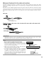
Waterproof treatment for the cable joint sections
Adequate waterproof treatment is required for the cables when installing the camera with cables
exposed or installing it under the eaves. The camera body is waterproof, but the cable ends are not
waterproof.
Be sure to use the supplied waterproof tape at the points where the cables are connected to apply
waterproof treatment in the following procedure. Failure to observe this or use of a tape other than
the provided waterproof tape (such as a vinyl tape) may cause water leakage resulting in malfunction.
LAN cable
Wind the tape in a
half-overlapping manner.
Wind the tape in a
half-overlapping manner.
Alarm input/output cable, power cable, microphone/line input cable, audio output cable
SW316L
SW316
Wind the tape in a
half-overlapping manner.
Wind the tape in a
half-overlapping manner.
IMPORTANT:
• Waterproof treatment is also to be applied to the 2P power cable (accessory), the 4P alarm
cable (accessory) and other connection cables if they are subject to rain.
Note:
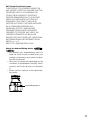
How to wind the supplied waterproof tape
• Stretch the tape by approx. twice (see the illustration)
and wind it around the cable. Insufficient tape stretch
causes insufficient waterproofing.
• Make sure to wind the tape so that it does not press
down on the hook of the network cable.
• Toinstallthisproductoutdoors,besuretowaterproof
the cables. Waterproof grade (IEC IP66 or equivalent)
is applied to this product only when it is installed correctly as described in these operating instructions and
appropriate waterproof treatment is applied. The mount
brackets are not waterproofed.
Stretch the tape to
about twice.
2x
hook
23
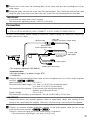
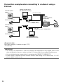
Connection example when connecting to a network using a
PoE hub
Powered speaker
(option)
Monitor for adjustment
(for adjustment use only)
PoE device (hub)
LAN cable
(category 5 or better,
straight, STP*)
Microphone (option)
LAN cable
(category 5 or better,
straight, STP*)
PC
Powered speaker
(option)
LAN cable
(category 5 or better, straight, STP*)
Microphone (option)
Monitor for adjustment
(for adjustment use only)
<Required cable>
LAN cable (category 5 or better, straight, STP*)
* E model only
IMPORTANT:
• The monitor for adjustment is used for checking the adjustment of the angular field of view
when installing the camera or when servicing. It is not provided for recording/monitoring use.
• Useaswitchinghuborarouterwhichiscompliantwith10BASE-T/100BASE-TX.
• Powersupplyisrequiredforeachnetworkcamera.WhenusingaPoEdevice(hub),12VDC
power supply is unnecessary.
24
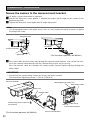
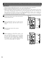
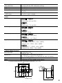
Secure the camera mount bracket when the camera is directly
installed on a wall
6 mm (W) x 10 mm (L) {1/4" (W) x
3/8" (L)} (long hole)
Use 4 screws (locally
procured) to secure the
camera mount bracket to a
wall or a junction box (locally
procured).
46 mm
{1-13/16"}
83.5 mm
{3-1/4"}
20 mm
{13/16"}
Cable access hole
Mounting screw x4
(locally procured)
Camera mount bracket
• Ifajunctionboxisused,
putting the boxes side by
side is recommended as
illustrated. (Use unused
junction boxes to pass
cables through for easy
cabling.)
6 mm (W) x 10 mm (L) {1/4" (W) x 3/8" (L)} (long hole)
83.5 mm 46 mm {1-13/16"}
Unused
{3-1/4"}
junction boxes
Mounting screw x4
(locally procured)
Junction boxes
Camera mount bracket
When the camera is installed on a wall using the adapter box
(E model only)
z Use 4 screws (locally
View from above (internal)
TOP
6 mm (W) x 10 mm (L)
{1/4" (W) x 3/8" (L)}
(long hole)
46 mm
{1-13/16"}
20 mm {13/16"}
83.5 mm
{3-1/4"}
procured) to secure the
adapter box (accessory) to a
wall or a junction box (locally
procured).
Cable access hole
Adapter box (accessory)
Cable access hole (used for wiring)
(G3/4" internal thread)
Mounting screw x4
(locally procured)
25
• Ifajunctionboxis
used, putting the
boxes side by side
is recommended
as shown in the
illustration at right.
(Use unused
junction boxes to
pass cables
through for easy
cabling.)
View from above (internal)
TOP
83.5 mm
{3-1/4"}
46 mm
{1-13/16"}
Unused junction
boxes
6 mm (W) x 10 mm (L)
{1/4" (W) x 3/8" (L)}
(long hole)
Junction boxes
Mounting screw x4
(locally procured)
x
Attach the camera mount bracket to the
left or right hinges of adapter box.
Adaptor box mounting screw (M4 x 35)
IMPORTANT:
• Ensurethattheadaptorboxmountingscrews
Hinges
(accessory) are firmly secured.
Recommended tightening torque:
M4: 0.78 N·m {0.58 lbf·ft}
• Ensurethatthemountingscrewsforadaptor
Adapter box
box/ camera mount bracket (accessory) are
Camera mount bracket
firmly secured.
Mounting screw for adapter box/
Recommended tightening torque:
camera mount bracket x4 (M5 x 20)
M5: 1.86 N·m {1.37 lbf·ft}
Note:
• Therightorlefthingesoftheadapter
box shall be selected so as to prevent
the motion of the camera mount bracket
from being interfered with by obstructions such as a wall when the camera
mount bracket is connected to the hinges of the adapter box.
(This illustration represents WV-SW316.)
26
c
Secure the mount bracket
cover x2 (accessories) to the
camera mount bracket with the
2 mount bracket cover screws
(accessories).
Mount bracket cover x2
(accessories)
IMPORTANT:
• Ensurethatthemountbracketcover
screws (accessory) are firmly secured.
Recommended tightening torque:
0.59 N·m {0.44 lbf·ft}
Camera mount bracket
Mount bracket cover screw x2
(M3 x 6) (accessories)
27
Insert/removeanSDHC/SDmemorycard(WV-SW316L/WV-SW316Only)
IMPORTANT:
• BeforeinsertinganSDHC/SDmemorycard,turnoffthepowerofthecamerafirst.
• WheninsertinganSDHC/SDmemorycard,makesurethedirection.
• BeforeremovingtheSDHC/SDmemorycard,select"Notuse"for"SDmemorycard"onthe
[SD memory card] tab of the setup menu first. Turn off the power after "Not use" selection, and
then unload the SDHC/SD memory card. When the SDHC/SD memory card is inserted or
removed with the power on, data in the SDHC/SD memory card may be damaged.
(☞ Operating Instructions (included in the CD-ROM))
z Loosen the 4 fixing screws of the front cover to
remove the front cover.
x Insert an SDHC/SD memory card fully into the
SDHC/SD memory card slot until a click is
heard.
c Attach the front cover to the camera.
(☞ Page 33)
v When
removing the SDHC/SD memory card
from the SDHC/SD memory card slot, detach
the front cover by following step 1, and push
the card until a click is heard. After the SDHC/
SD memory card is removed, attach the front
cover to the camera again. (☞ Page 33)
28
Label side
Adjustment
z Be sure to view the monitor for adjustment when the camera angle is adjusted.
Supply power to this unit, connect the monitor for adjustment (e.g. a small LCD) to the monitor
output jack, and adjust the camera angle (turn off the power after view angle adjustment for safety).
q Loosen the 4 fixing screws of the front cover to remove the front cover.
w Connect the monitor output jack and the monitor for adjustment with the RCA pin cable
(locally procured).
Front cover
Monitor output jack
Fixing screw x4
<Frontcover>(ThisillustrationrepresentsWV-SW316.)
e Repeat the steps (1) and (2) to adjust the camera angle.
(1) Loosen the panning lock screw and rotate the camera head horizontally to adjust panning.
(2) Loosen the tilting lock screw and rotate the camera head vertically to adjust tilting.
(3) Tighten the panning lock screw and tilting lock screw after camera angle adjustment.
IMPORTANT:
• After camera angle adjustment, the panning lock screw and tilting lock screw shall be securely tightened.
Recommended tightening torque: 2.45 N·m {1.8 lbf·ft}
Tilting lock screw
Panning lock screw
Notes:
• Useahexagonalwrenchwithwidthacrossflatsof4mm(locallyprocured)toloosenortighten
the panning lock screw and tilting lock screw.
• Approximately1rotationoflooseningthepanninglockscrewandtiltinglockscrewallowscamera angle adjustment. Do not loosen the screws beyond necessity.
• Thecamerabodyshallbeheldwhenthepanninglockscrewortiltinglockscrewisloosened.
• Focus adjustment (☞ page 30-32) shall be performed at the same time panning and tilting
adjustments are performed.
29
x Adjust the angular field of view and the focus.
Adjust the angular field of view in accordance with the distance between the camera lens and a
photographic subject. These adjustments shall be performed together with the camera angle
adjustment.
<WV-SW316L/WV-SW316>
Auto focus (AF) button
TELE button
WIDE button
When adjusting the angular field of view and the focus from the setup menu
Refer to the Operating Instructions (included in the CD-ROM) for how to perform the manual focus
adjustment from the setup menu.
When adjusting the angular field of view and the focus with the panel of the camera
q Press the TELE or WIDE buttons to move the knob between TELE and WIDE to obtain the
appropriate angular field of view.
Note:
• Whilethebuttonishelddown,theangleoftheviewmovesinthe"T"or"W"direction.
• WhentheangularfieldofviewisadjustedontheTELEside,opticalzoomisapplieduntil3.2x,
and if there are any adjustments above this, extra optical zoom is applied.
• Whentheimagecapturesizeunder"VGA"isapplied,thezoomfactorcanbeadjustedupto
2x without deterioration of image quality.
• Thezoomingfactorisdisplayedonthetoprightofthescreen.
• When using the TELE or WIDE buttons to perform operations, the zoom factor stops once at 3.2x. If
operations are continued, the angle of the view can be moved even more in the "T" or "W" directions.
w When the auto focus (AF) button is pressed, the auto focus (AF) indicator will light for around
10 seconds, and the focus is automatically adjusted.
IMPORTANT:
• Donottouchthelens.
• Defocus may be caused by the reinstalled front cover. In this case, perform the auto focus
function from the setup menu.
30
Note:
• When shooting in the following place or the following subjects, focus may not be adjusted
automatically. In this case, adjust the focus manually from the setup menu. Refer to the
Operating Instructions (included in the CD-ROM) for how to perform the manual focus adjustment from the setup menu.
• Subj.withlargeilluminancechange
• Subj.movingfrequently
• Subj.withreflectionorextrabrightness
• Subj.withlowilluminance
• Placewherethefrontcovereasilybecomesdirty
• Subj.throughawindow
• Subj.withlesscontrastsuchaswhitewall
• Subj.withheavyflicker
• If the 2x extra optical zoom is applied when "1280x960", "1280x720" is selected for the image capture
size, the image quality will be deteriorated because the effect of Extra Optical Zoom is not provided.
• Whenimagesinthenear-infraredlightareachangefrom color to black & white, out-of-focus
may be occurred according to the nature of optical property. In this case, the focus can automatically be corrected by selecting "Auto" or "Preset" for "Adjusting method" on the setup
menu (The focus will not automatically be adjusted according to the illumination level change
once the focus is corrected.) Refer to the Operating Instructions (included in the CD-ROM) for
how to set "Adjusting method" on the setup menu.
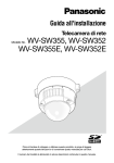
<WV-SW314>
Zoom ring
FOCUS ADJUSTMENT
Focus ring
LOW
HIGH
.......|............
INDICATOR
PEAK HOLD
775
780
BEST
FOCUS
Focus lock knob
Zoom lock knob
Focus assist button (F.A.)/
Extra optical zoom button
q Loosen the zoom lock knob and the focus lock knob, then move them to adjust for the appropriate viewing angle of the target.
Note:
• The focus may not be adjusted appropriately when the zoom ring is positioned at the "W"
(or "T") end. In this case, adjust the focus again by slightly moving the zoom ring to the direction of "T" (or "W").
31
w To adjust the angular field of view with a higher zooming effect even after adjusting the angular
field of view almost fully in the "T" direction, hold down the focus assist button (F.A.)/extra optical zoom button for 5 seconds or more. 2x extra optical zoom will be applied. When the image
capture size under "VGA" is applied, the zoom factor can be adjusted up to 2x without deterioration of image quality. When holding down the focus assist button (F.A.)/extra optical zoom
button again for 5 seconds or more, 1x extra optical zoom will be applied.
e Tighten the zoom lock knob.
r Press the focus assist (F.A.) button.
→ "FOCUS ADJUSTMENT" menu will be displayed.
The focus assist function will be activated to perform the optimum adjustment.
t When the focus lock knob is positioned near the best focus position, the position will automatically be memorized as the "PEAK HOLD" position. (The closer the focus ring is positioned to
the best focus position, the greater the "PEAK HOLD" value becomes.)
y When the focus lock knob is moved, the current focus position will be indicated on
"INDICATOR". Adjust the focus position so that the indicator value goes close to the "PEAK
HOLD" position.
u When the indicator value goes to the best focus position, "BEST FOCUS" will be displayed in
reverse at the lower right corner of the screen.
i Tighten the focus lock knob so as to fix the best focus position.
o Press the focus assist (F.A.) button again to close the "FOCUS ADJUSTMENT" menu.
(No operation for 3 minutes also closes the menu.)
IMPORTANT:
• When using a model equipped with the focus assist (F. A.) function, defocus may be caused by the
dome cover attached.
In this case, the focus adjustment will be easier by detaching the dome cover and moving the
focus ring to the "N" direction.
• Beforeattachingthedomecover,makesurethatthesubjectispresent.
Note:
• Ifthezoomlockknobisfullyrotatedinthe"W"direction,theperipherymaybecomedark.In
such a case, rotate the zoom lock knob in the "T" direction for readjustment.
• When shooting the following subjects, close the "FOCUS ADJUSTMENT" menu by pressing
the focus assist (F.A.) button again, or adjust the focus to obtain the best focus position while
monitoring images from the camera.
•Placewherethefrontcovereasilybecomesdirty
•Subj.movingfrequently
•Subj.withlargeilluminancechange
•Subj.withlowilluminance
•Subj.withreflectionorextrabrightness
•Subj.throughawindow
•Subj.withlesscontrastsuchaswhitewall
•Subj.withheavyflicker
• If the zoom lock knob is slightly tightened before the zoom is adjusted, the ring will become
stable, making fine adjustments easier to perform.
• If the focus lock knob is slightly tightened before the focus is adjusted, the ring will become
stable, making fine adjustments easier to perform.
• In case the angular field of view has changed during adjustment, close the "FOCUS
ADJUSTMENT" menu once by pressing the focus assist (F.A.) button. (When the angular field
of view changes, the indicator values of "PEAK HOLD" and "INDICATOR" also change.) After
fixing the angular field of view, retry Step 3.
• If the 2x extra optical zoom is applied when "1280x960", "1280x720" is selected for the image capture
size, the image quality will be deteriorated because the effect of Extra Optical Zoom is not provided.
32
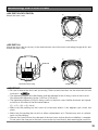
Mounting the front cover
<WV-SW316L/WV-SW316>
(1)
(3)
Mount the front cover.
(4)
(2)
Fixing screw x4
<WV-SW314>
Attach the desiccant (accessory) to the inner bottom side of the front cover along the guide rib, and
mount the front cover.
(1)
(3)
Guide rib
(4)
(2)
Desiccant (accessory)
Fixing screw x4
IMPORTANT:
• Besuretoattachthedesiccant(accessory).Refertotheinstructionsforthedesiccantforhow
to attach it. SW314
• Thetighteningtorquedescribedbelowshallbefollowedforthe4fixingscrewsoffrontcover.
Recommended tightening torque: 0.59 N·m {0.44 lbf·ft}
• Thetighteningsequenceofthe4fixingscrewsofthefrontcovershallbeobservedandrepeated twice as described in the illustration above.
((1) →(2) →(3) →(4), twice)
• Make sure the packing has not come off or become askew. If this happens put it back into
place.
• Makesurethepackinghasnodustorothercontaminantsonit.Removeanydustorcontaminants on the packing.
• Remove the cover film from the clear part of the front cover section after the installation is complete.
Do not touch the clear part of the front cover section by hand directly after removing the cover film.
33
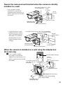
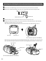
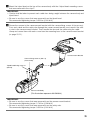
Attaching the mounting surface on the top surface of the camera body
When the mounting surface is changed to the top surface of the camera body
z Remove the 4 sunshield fixing screws from the camera body and remove the sunshield.
x Remove the 4 tripod head fixing screws from the camera body and remove the tripod head.
Tripod head fixing screw x4
Tripod head
c Loosen the fixing screw x1 and remove the rear cover, and remove the cap.
v Rotate each cable in the direction of the arrow (clockwise) as illustrated and pass them between
opening in the upper groove of the main body.
Then, attach the cap to the lower groove, and secure the rear cover with the fixing screw x1.
Rear cover
Fixing screw x1
(This illustration represents WV-SW316.)
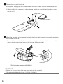
Attach the rear cover to the front cover by hooking attachment hole 1 of the rear cover to the tab on the
front cover while passing the protrusion of the front cover through attachment hole 2 of the rear cover.
Tab Protrusion
Attachment hole 1
Upper groove
Cap
(This illustration represents WV-SW316.)
34
Attachment
hole 2
b Mount the tripod head on the top of the camera body with the 4 tripod head mounting screws
that were removed in the step 2.
IMPORTANT:
• Cautionshallbetakentopreventeachcablefrombeingcaughtbetweenthecamerabodyand
tripod head.
• Besuretousethescrewsthatwereremovedfromthetripodhead.
Recommended tightening torque: 0.59 N·m {0.44 lbf·ft}
n Secure the camera to the camera mount bracket with the camera fixing screws x3 (accessory).
Pass each cable and the safety wire through the camera mount bracket, and connect the safety wire to the camera mount bracket. Then, bundle the wire and the cable using the cable
clamp and secure them with each screw from the mounting boss to the camera mount bracket
(☞ page 20-21).
Camera mount bracket
Camera fixing screw x3 (M4 x 8)
(accessories)
Tripod head fixing screw x4
(M3x10)
Camera main body
(This illustration represents WV-SW316.)
IMPORTANT:
• Besuretousethescrewsthatwereremovedfromthecameramountbracket.
Recommended tightening torque: 0.78 N·m {0.58 lbf·ft}
• Besuretousethescrewsthatwereremovedfromthesafetywire.
Recommended tightening torque: 0.59 N·m {0.44 lbf·ft}
35
m Remove the sunshield backside.
As illustrated, opening up the sunshield in both directions makes it easier to remove the rear
part of the sunshield.
•When installing the camera to a ceiling, the rear part of the sunshield and the fixing screws
are not used.
Fixing screw x2
Rear part of sunshield
, Mount the sunshield on the camera body with the 4 sunshield mounting screws after removing
the sunshield backside.
•The sunshield is attached to the camera by inserting the protrusions on the rear cover of the
camera into the attachment holes on the rear part of the sunshield.
Attachment hole
Rear part of sunshield
Protrusion
(This illustration represents WV-SW316.)
IMPORTANT:
• Besuretousethescrewsthatwereremovedfromthesunshield.
Recommended tightening torque: 0.59 N·m {0.44 lbf·ft}
36
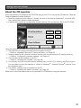
Using the CD-ROM
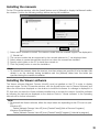
About the CD launcher
Insert the provided CD-ROM into the CD-ROM drive of your PC to start up the CD launcher. Then the
License Agreement will be displayed.
• Read the Agreement and choose "I accept the term in the license agreement", and click [OK].
Then the launcher window will be displayed.
• Ifthelauncherwindowisnotdisplayed,doubleclickthe"CDLauncher.exe"fileontheCD-ROM.
q
w
e
r
t
UsingthesuppliedCD-ROM,thefollowingactionscanbeperformed.
q ThePanasonicIPsettingsoftwarecanbeinstalledonthePC.
→ Referto"InstallingPanasonicIPsettingsoftware".(☞ Page 38)
w Settingsrelatedtothecamera'snetworkcanbesetfromthePanasonicIPsettingsoftware.
→ Referto"Configurethenetworksettings".(☞ Page 40)
e ThemanualscanbeinstalledonthePC.
→ Referto"Installingthemanuals".(☞ Page 39)
r YoucanalsoviewthemanualswithoutinstallingthemtothePCbyclickingthe[Open]button.
Youcanselecttoviewthemanualsor"NotesonWindows® / Internet Explorer®versions"from
thedisplayedmenu.
t TheViewersoftwarecanbeinstalledonthePC.
→ Referto"InstallingtheViewersoftware".(☞ Page 39)
MakesuretoreadthereadmefileontheprovidedCD-ROMbeforeusingthesoftware.
37
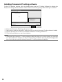
Installing Panasonic IP setting software
On the CD launcher window, click the [Install] button next to [IP Setting Software] to display the
PanasonicIPsettingsoftwareinstallationwindow.Confirmthefollowingsettingsbeforestartingtheinstallation.
q
w
e
r
q
w
e
r
SelectthePanasonicIPsettingsoftwaretoinstall.
SelectwheretocreatethePanasonicIPsettingshortcuticonwhenthePanasonicIPsettingsoftwareisinstalled.
SpecifywhichfolderonthePCtoinstallthePanasonicIPsettingsoftwareto.
Clickthe[Install]buttontostarttheinstallation.
Note:
• TouninstallthePanasonicIPsettingsoftwaredeletetheshortcuticonfromwhereyouspecified
it to be installed (the default is on the desktop) during installation and the [EasyIPConfig] folder
from the folder you specified during Panasonic IP setting software installation.
38
Installing the manuals
OntheCDlauncherwindow,clickthe[Install]buttonnextto[Manual]todisplaytheManualinstallationwindow.Confirmthefollowingsettingsbeforestartingtheinstallation.
w
q
e
r
t
q Selectwhichmanualstoinstall.Thecameramodelsthatthemanualssupportaredisplayedin
w"ModelList".
w Thecameramodelsthataresupportedbythemanualsselectedinqaredisplayedhere.
e Selectwheretocreatethemanualsshortcuticonwhenthemanualsareinstalled.
r SpecifywhichfolderonthePCtoinstallthemanualsto.
t Clickthe[Install]buttontostarttheinstallation.
Note:
• Touninstallthemanualsdeletetheshortcuticonfromwhereyouspecifiedittobeinstalled(the
default is on the desktop) during installation and the [Manual] folder from the folder you
specified during the manuals installation.
Installing the Viewer software
The Viewer software (Network Camera View4S) must be installed on the PC in order to display
cameraimages.OntheCDlauncherwindow,clickthe[Install]buttonnextto[ViewerSoftware],and
followtheinstructionsdisplayedonthewindowtoinstallthesoftware.Amessageisdisplayedifa
PCthatdoesnothavetheViewersoftwareinstalledtriestoaccessthecamera.Installthesoftware
byfollowingtheinstructionsdisplayedonthewindow.Referto"Viewersoftware"intheOperating
Instructionsforfurtherinformation.
Note:
• TouninstalltheViewersoftware,followthestepsbelowfordependingontheOSusedonyour
PC.
Windows XP:
Delete [Network Camera View 4S] from [Control Panel]-[Add or Remove Programs].
Windows Vista/Windows 7:
Delete [Network Camera View 4S] from [Control Panel]-[Programs]-[Uninstall a program].
39
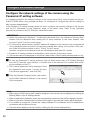
Configure the network settings
Configure the network settings of the camera using the
Panasonic IP setting software
ItispossibletoperformthenetworksettingsofthecamerausingtheIPsetupsoftwareontheprovidedCD-ROM.Whenusingmultiplecameras,itisnecessarytoconfigurethenetworksettingsof
eachcameraindependently.
IfthePanasonicIPsettingsoftwaredoesnotwork,configurethenetworksettingsofthecamera
and the PC individually on the "Network" page of the setup menu. Refer to the Operating
Instructions(includedintheCD-ROM)forfurtherinformation.
IMPORTANT:
• When using Microsoft Windows 7 or Microsoft Windows Vista, the "Windows Security Alert"
window may be displayed when starting the IP setup software. In this case, disable "User
AccountControl"fromthecontrolpanel.
• Forthesecurityenhancement,theMACaddress/IPaddressofthecameratobeconfiguredwill
notbedisplayedwhenaround20minuteshavepassedafterturningonthepowerofthecamera.(Whentheeffectiveperiodissetto"20min"intheIPsetup)
Howevercamerasintheinitialsetmodearestilldisplayedevenafter20minutes.
• PanasonicIPsettingsoftwareisinoperableinothersubnetsviathesamerouter.
• ThiscameracannotbedisplayedorsetwithanolderversionoftheIPsetupsoftware(version2.xx).
z TostartthePanasonicIPsettingsoftware,clickthe[Run]buttonnextto[IPSettingSoftware]
fromtheCDlaunchermenuwindow,ordouble-clickontheshortcuticoncreatedafterinstallingthesoftwareonthePC.
• TheLicenseAgreementwillbedisplayed.Read
the Agreement and choose "I accept the term
in the license agreement", and click [OK].
x Clickthe[NetworkSettings]buttonafterselectingtheMACaddress/IPaddressofthecamera
tobeconfigured.
Note:
• WhenusingaDHCPserver,theIPaddressassignedtothecameracanbedisplayedbyclickingthe
[Search]buttonoftheIPsettingsoftware.
• WhenaduplicateIPaddressisused,thecorrespondingcameranumberwillbedisplayedshaded.
• Whenthe[AccessCamera]buttonisclicked,liveimagesoftheselectedcamerawillbedisplayed.
• Itispossibletochangethe"Cameralist"displaybetweenIPv4addressesandIPv6addressesin
accordancewiththeprotocolinuse.
• Theinformationdisplayedcanbesortedbyclickingthetitleofeachdisplayeditem.
40
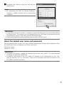
c Complete each network setup item and click the
[Save]button.
Note:
• By unchecking the "Wait for camera restarting."
checkbox, multiple cameras can be continuously
configured.
IMPORTANT:
• Itmaytakeforaround2minutestocompletetouploadthesettingstothecameraafterclicking
the[Save]button.ThesettingsmaybeinvalidatedwhentheLANcableisdisconnectedbefore
completingtheupload.Inthiscase,performthesettingsagain.
• Whenusingafirewall(includingsoftware),allowaccesstoallUDPports.
About the default user name and password
Clickthe[Setup]buttononthe"Live"page,theuserauthenticationwindowwillbedisplayed.Enter
thedefaultusernameandpasswordasfollows,andlogin.
User name: admin
Password:12345
IMPORTANT:
• Toenhancethesecurity,changethepasswordfortheusername"admin".Itisrecommended
tochangethispasswordperiodically.
• To enhance the security of the "Live" page, it is possible to set authentication for the "Live"
page by selecting "On" for "User auth.". Refer to the Operating Instructions (included in the
CD-ROM)forfurtherinformation.
41
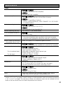
Troubleshooting
Before asking for repairs, check the symptoms with the following table.
Contact your dealer if a problem cannot be solved even after checking and trying the solution in the
table or a problem is not described below.
Symptom
Cause/solution
Reference
pages
SW316
When using DC power supply SW316L
• Is12VDCpowersupplyconnectedtothe2P
power supply cable?
→ Check whether the connection is appropriately established.
• Is the AC adaptor in use compliant with the
Specifications?
→ Check the Specifications regarding AC
adaptor.
Power is not turned on.
When the IR LED lights a
part or all of the screen
appears blurred.
When the IR LED lights
the camera switches
between color mode and
black-and-white mode.
42
When using a PoE device for power supply
• ArethePoEdeviceandthenetworkcableof
the camera connected using a LAN cable?
→ Check whether the connection is appropriately established.
• DependingonthePoEdevice,thepowersupply will stop when the demanded power
exceeds its total power limit for all PoE ports.
→ Refer to the operating instructions of the
PoE device in use.
• Isthereawallorotherreflectingsurfaceor
object near the camera (including areas not
displayed in images)? SW316L
→ Adjust the camera angle so that light from
the IR LED is not reflected.
21
29
• Thesubjectmaybetooclosetothecamera.
SW316L
→ Adjust the distance between the camera
and the subject.
29
Specifications
•Basic
Power source:
SW316L
SW316
12 V DC, PoE (IEEE802.3af compliant)
SW314
Power consumption:
PoE (IEEE802.3af compliant)
SW316L
SW316
12 V DC*: 850 mA, PoE 48 V: 200 mA (Class 0 device)
SW314
Ambient operating temperature:
PoE 48 V: 70 mA (Class 0 device)
* FOR UL LISTED MODEL(S), ONLY CONNECT 12 V DC CLASS
2 POWER SUPPLY.
SW316L
SW316
–40 °C to +50 °C {-40 °F to 122 °F}*
SW314
Ambient operating humidity:
IR LED irradiation distance:
Waterproof:
Monitor output (for adjusting
the angular field of view):
EXT I/O terminal cable:
Microphone/line input cable:
For microphone input:
For line input:
Audio output cable:
Dimensions:
Mass:
–10 °C to +50 °C {14 °F to 122 °F}
Less than 90 % (no condensation)
SW316L
15 m {49.21 feet}
Camera: IP66 (IEC60529)
* Only when installation work specified in this book is properly
performed and appropriate waterproof treatment is performed
VBS: 1.0 V [p-p]/75 Ω, composite signal, RCA jack
SW316L
SW316
ALARM IN, DAY/NIGHT IN, ALARM OUT, AUX OUT (x1 for each)
SW316L
SW316
SW316L
SW316
SW316L
SW316
ø3.5 mm monaural mini jack
Input impedance: Approx. 2 kΩ
Applicable microphone: Plug-in power type
Supply voltage: 2.5 V ±0.5 V
Input level: Approx. –10 dBV
ø3.5 mm stereo mini jack (monaural output)
Output impedance: Approx. 600 Ω
Line level
94 (W) mm x 89 (H) mm x ø226 mm
{3-7/10 inches (W) x 3-1/2 inches (H) x ø8-7/8 inches}
(including projection of the base cover fixing screw)
Approx. 1.4 kg {3.09 lbs}
SW314
Approx. 1.3 kg {2.87 lbs}
Finish:
Main body: Aluminum die cast/resin, metallic silver coating
Front cover section clear part: Polycarbonate resin
* When using this product without turning the power off. (However, the temperature inside the camera
shall be -10 °C {14 °F} or higher.) Perform settings or startup operations when the ambient temperature
is -30 °C {-22 °F} or higher. The auto focus function and motorized zoom are not available until the
heater unit of the camera raises the internal temperature of the camera.
43
•Camera
Image sensor:
Effective pixels:
Scanning area:
Scanning system:
Minimum illumination:
1/3-type MOS image sensor
Approx. 1.3 megapixels
4.80 mm (H) × 3.60 mm(V) {3/16 inches (H) x 5/32 inches (V)}
Progressive
SW316L
Color: 0.3 lx {0.03 footcandle}
(F1.3, Auto slow shutter: Off (1/30 s), Gain: On(High))
0.019 lx {0.0019 footcandle}
(F1.3, Auto slow shutter: max. 16/30 s, Gain: On(High))*
BW: 0 lx {0.000 footcandle}
(F1.3, Auto slow shutter: Off (1/30 s), Gain: On(High),
when the IR LED is lit)
SW316
Color: 0.3 lx {0.03 footcandle}
(F1.3, Auto slow shutter: Off (1/30 s), Gain: On(High))
0.019 lx {0.0019 footcandle}
(F1.3, Auto slow shutter: max. 16/30 s, Gain: On(High))*
BW: 0.05 lx {0.005 footcandle}
(F1.3, Auto slow shutter: Off (1/30 s), Gain: On(High))
0.003 lx {0.0003 footcandle}
(F1.3, Auto slow shutter: max. 16/30 s, Gain: On(High))*
SW314
Super-Dynamic:
Dynamic range:
Face SD:
Gain (AGC):
Adaptive black stretch:
Back light compensation (BLC):
Light control mode setting:
Shutter speed:
Auto slow shutter:
Color/BW:
IR LED Light:
White balance:
Digital noise reduction:
44
Color: 0.3 lx {0.03 footcandle}
(F1.3, Auto slow shutter: Off (1/30 s), Gain: On(High))
0.019 lx {0.0019 footcandle}
(F1.3, Auto slow shutter: max. 16/30 s, Gain: On(High))*
BW: 0.2 lx {0.02 footcandle}
(F1.3, Auto slow shutter: Off (1/30 s), Gain: On(High))
0.013 lx {0.0013 footcandle}
(F1.3, Auto slow shutter: max. 16/30 s, Gain: On(High))*
* Converted value
On/Off
52 dB typ. (Super-Dynamic: On, light control: indoor scene)
On/Off
On(High)/ On(Mid)/ On(Low)/ Off
On/Off
On/Off
Indoor scene (50 Hz/60 Hz)/ Outdoor scene/ Fix shutter
1/30, 3/100, 3/120, 2/100, 2/120, 1/100, 1/120, 1/250, 1/500,
1/1000, 1/2000, 1/4000, 1/10000 (only at Super-Dynamic Off)
Off (1/30 s), max. 2/30 s, max. 4/30 s, max. 6/30 s,
max. 10/30 s, max. 16/30 s
On/ Off/ AUTO1/ AUTO2
SW316L
Off/ Auto (High)/ Auto (Mid)/ Auto (Low)
ATW1/ ATW2/ AWC
High/Low
Video analytics
Face detection:
Privacy zone:
VIQS:
Camera title on screen:
Video motion detection
(VMD alarm):
•Lens
Zoom ratio:
On/Off (with the XML notification setting)
On/Off (up to 2 zones available)
On/Off
Up to 20 characters (alphanumeric characters, marks)
On/Off
On/Off, 4 areas available
SW316L
SW316
3.2x
Extra zoom: 6.4x (at VGA)
SW314
3.6x
Extra zoom: 7.2x (at VGA)
Focal length:
SW316L
SW316
3.1 mm - 10 mm
SW314
Maximum aperture ratio:
2.8 mm - 10 mm
SW316L
SW316
1:1.3 (WIDE) - 1:3.0 (TELE)
SW314
1:1.3 (WIDE) - 1:3.1 (TELE)
Angular field of view:
SW316L
SW316
Horizontal: 27.9 ° (TELE) - 90.6 ° (WIDE)
Vertical: 20.9 ° (TELE) - 66.9 ° (WIDE)
SW314
Horizontal: 27.7 ° (TELE) - 100.3 ° (WIDE)
Vertical: 20.8 ° (TELE) - 73.6 ° (WIDE)
•CameraMountbracket
Adjusting angle:
Dimensions:
Aluminum die cast, metallic silver coating
<Camera mount bracket dimensional drawing> (unit : mm)
33.5
6
ø3 26
ø
83.5
121
45°
125
114
46
125
Mass:
Finish:
Horizontal: ±100 °
Vertical: +30 °, -90°
125(W) mm x 125 (H) mm x ø108 mm
{4-15/16 inches (W) x 4-15/16 inches (H) x ø4-1/4 inches}
Approx. 220 g {0.49 lbs}
20
4-6 (W) x 10 (L)
80
108
45
•Network
Network:
Resolution:
Image compression method*1 *2:
Transmission interval:
Audio compression method:
Bandwidth control:
Protocol:
OS*3 *4:
Browser:
Maximum concurrent
access number:
FTP client:
46
10BASE-T/100BASE-TX, RJ45 connector
Aspect ratio: 4:3
H.264
1280×960/ VGA (640×480)/
QVGA (320×240), max. 30 fps
MPEG-4
VGA (640×480)/ QVGA (320×240),
max. 30 fps
JPEG (MJPEG) 1280×960/ VGA (640×480)/
QVGA (320×240), max. 30 fps
Aspect ratio: 16:9
H.264
1280×720/ 640×360/ 320×180, max. 30 fps
JPEG (MJPEG) 1280×720/ 640×360/ 320×180, max. 30 fps
* MPEG-4 is not supported.
H.264/MPEG4
Image quality: Low/ Normal/ Fine
Transmission type: Unicast/Multicast
Audio bit rate:
Constant bit rate/Best effort: 64 kbps/ 128 kbps/ 256 kbps/
384 kbps/ 512 kbps/ 768 kbps/ 1024 kbps/ 1536 kbps/
2048 kbps/ 3072 kbps/ 4096 kbps/ *8192 kbps
* only in H.264 mode
Frame rate:
1 fps/ 3 fps/ 5 fps/ 7.5 fps/ 10 fps/ 12 fps/ 15 fps/ 20 fps/
30 fps
JPEG (MJPEG)
Image quality:
0 SUPER FINE/ 1 FINE/ 2/ 3/ 4/ 5 NORMAL/ 6/ 7/ 8/
9 LOW (10 steps: 0-9)
Transmission type: PULL/PUSH
0.1 fps - 30 fps (JPEG frame rate will be restricted when displaying both JPEG and H.264/MPEG-4 images.)
G.726 (ADPCM) 32 kbps/16 kbps
G.711 64 kbps
Unlimited/ 64 kbps/ 128 kbps/ 256 kbps/ 384 kbps/
512 kbps/ 768 kbps/ 1024 kbps/ 2048 kbps/ 4096 kbps/
8192 kbps
IPv6: TCP/IP, UDP/IP, HTTP, HTTPS, RTP, FTP, SMTP, DNS, NTP,
SNMP, DHCPv6, MLD, ICMP, ARP
IPv4: TCP/IP, UDP/IP, HTTP, HTTPS, RTSP, RTP, RTP/RTCP, FTP,
SMTP, DHCP, DNS, DDNS, NTP, SNMP, UPnP, IGMP, ICMP, ARP
Microsoft Windows 7
Microsoft Windows Vista
Microsoft Windows XP SP3
Windows Internet Explorer 9.0 (32-bit)
Windows Internet Explorer 8.0 (32-bit)
Windows Internet Explorer 7.0 (32-bit)
Microsoft Internet Explorer 6.0 SP3
14 (Depends on network conditions)
Alarm image transmission, FTP periodic transmission (When the
FTP transmission is failed, backup on an optional SDHC/SD
SW316 )
memory card is available. SW316L
Multi-screen:
Compatible SDHC/
SD memory card (option):
Cellular phone compatibility:
Mobile terminal compatibility*5:
Up to 16 camera images can be displayed simultaneously on a
multi-screen. (Including the camera itself )
Manufactured by Panasonic
SDHC memory card: 4 GB, 8 GB, 16 GB, 32 GB
SD memory card: 256 MB, 512 MB, 1 GB, 2 GB
(except miniSD card and microSD card)
JPEG image, AUX control (by access level)
iPad, iPhone, iPod touch (iOS 4.2.1 or later)
AndroidTM mobile terminals (As of January, 2012)
*1 Either H.264 or MPEG-4 is selectable.
*2 Transmission for 2 streams can be individually set in the same compression method.
*3 For further information about PC system requirements and precautions for when using
Microsoft Windows 7, Microsoft Windows Vista, or Windows Internet Explorer, click "Manual" "Open" from the supplied CD-ROM and refer to "Notes on Windows® / Internet Explorer® versions".
*4 When using IPv6 for communication, use Microsoft Windows 7 or Microsoft Windows Vista.
*5 For information on the camera models of the supported operating systems, refer to our website
at http://panasonic.net/pss/security/support/info.html.
47
Standard accessories
Installation Guide (this document) ......................................................1 pc.
Warranty card (P model only) .............................................................1 pc.
CD-ROM*1 ........................................................................................1 pc.
Code label*2 ......................................................................................1 pc.
The following parts are used during installation procedures.
4P alarm cable SW316L
..............................................1 pc.
SW316
2P power cable SW316L
.............................................1 pc.
SW316
Waterproof tape.................................................................................1 pc.
Adapter box (E model only)................................................................1 pc.
Camera mount bracket ......................................................................1 pc.
Mount bracket cover..........................................................................2 pcs.
Adapter box mounting screw (M4 x 35) (E model only).......................1 pc.
Mounting screws for adapter box/ camera mount bracket (M5 x 20)
(E model only)....................................................................................5 pcs. (of them, 1 for spare)
Camera fixing screw (M4 x 8).............................................................4 pcs. (of them, 1 for spare)
Mount bracket cover screw (M3 x 6)..................................................3 pcs. (of them, 1 for spare)
Desiccant SW314 ........................................................................1 pc.
*1 The CD-ROM contains the operating instructions and different kinds of tool software programs.
*2 This label may be required for network management. The network administrator shall retain the
code label.
Optional accessories
User License Accessory (For MPEG-4) ........................BB-HCA5A (P model)
BB-HCA5CE (E model, Korea*)
* Required in Korea
User License Accessory (For H.264) ............................BB-HCA8A (P model)
BB-HCA8CE (E model, Korea*)
* Required in Korea
Adapter Box ................................................................WV-Q120
48
49
Information for Users on Collection and Disposal of Old Equipment and used
Batteries
These symbols on the products, packaging, and/or accompanying documents mean
that used electrical and electronic products and batteries should not be mixed with
general household waste.
For proper treatment, recovery and recycling of old products and used batteries, please
take them to applicable collection points, in accordance with your national legislation
and the Directives 2002/96/EC and 2006/66/EC.
By disposing of these products and batteries correctly, you will help to save valuable
resources and prevent any potential negative effects on human health and the
environment which could otherwise arise from inappropriate waste handling.
For more information about collection and recycling of old products and batteries,
please contact your local municipality, your waste disposal service or the point of sale
where you purchased the items.
Penalties may be applicable for incorrect disposal of this waste, in accordance with
national legislation.
For business users in the European Union
If you wish to discard electrical and electronic equipment, please contact your dealer or
supplier for further information.
[Information on Disposal in other Countries outside the European Union]
These symbols are only valid in the European Union. If you wish to discard these items,
please contact your local authorities or dealer and ask for the correct method of
disposal.
Cd
Note for the battery symbol (bottom two symbol examples):
This symbol might be used in combination with a chemical symbol. In this case it
complies with the requirement set by the Directive for the chemical involved.
For U.S. and Canada:
For Europe and other countries:
Panasonic System Communications
Company of North America,
Unit of Panasonic Corporation
of North America
Panasonic Corporation
www.panasonic.com/business/
For customer support, call 1.800.528.6747
Three Panasonic Way, Secaucus,
New Jersey 07094 U.S.A.
http://panasonic.net
Importer's name and address to follow EU rules:
Panasonic Testing Centre
Panasonic Marketing Europe GmbH
Winsbergring 15, 22525 Hamburg F.R.Germany
Panasonic Canada Inc.
5770 Ambler Drive, Mississauga,
Ontario, L4W 2T3 Canada
(905)624-5010
www.panasonic.ca
© Panasonic System Networks Co., Ltd. 2012
Cs1111-2012
PGQX1054XA
Printed in China