1
Operating Instructions
Recording Software
Update Software
Model No.
WV-ASR500 Series
This manual covers the models: WV-ASR500 Series consists of Recording Software (WV-ASRE501,
WV-ASRE501W, WV-ASRE516, WV-ASRE516W, WV-ASRE532, WV-ASRE532W, WV-ASRE564,
WV-ASRE564W, WV-ASRE571, WV-ASRE571W, WV-ASRE572, WV-ASRE572W, WV-ASRE599,
WV-ASRE599W), and Update Software (WV-ASRM501, WV-ASRM501W, WV-ASRM516, WV-ASRM516W,
WV-ASRM532, WV-ASRM532W, WV-ASRM564, WV-ASRM564W, WV-ASRM571, WV-ASRM571W,
WV-ASRX501, WV-ASRX501W, WV-ASRX516, WV-ASRX516W, WV-ASRX532, WV-ASRX532W,
WV-ASRX564, WV-ASRX564W, WV-ASRX571, WV-ASRX571W).
Before attempting to connect or operate this product,
please read these instructions carefully and save this manual for future use.
The model number is abbreviated in some descriptions in this manual.
CONTENTS
Preface.................................................................................................................................................................... 3
Software configuration........................................................................................................................................ 3
System configuration.......................................................................................................................................... 3
System specifications......................................................................................................................................... 4
Compatible devices............................................................................................................................................. 4
Features.............................................................................................................................................................. 6
Standard accessories.......................................................................................................................................... 6
Trademarks and registered trademarks.............................................................................................................. 7
Abbreviations...................................................................................................................................................... 7
Open software..................................................................................................................................................... 7
Disclaimer............................................................................................................................................................ 7
System installation checklist................................................................................................................................... 8
Installing the software........................................................................................................................................... 10
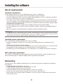
Server requirements.......................................................................................................................................... 10
Networking........................................................................................................................................................ 10
Software overview................................................................................................................................................. 11
License.............................................................................................................................................................. 11
Logging in.......................................................................................................................................................... 11
About the Client................................................................................................................................................ 12
Main pages........................................................................................................................................................ 12
Config (Setup) page overview............................................................................................................................... 13
Add Systems..................................................................................................................................................... 14
System.............................................................................................................................................................. 15
Add IP Cameras................................................................................................................................................ 19
IP Camera Recording........................................................................................................................................ 20
Analog Camera Recording................................................................................................................................ 21
Camera Settings................................................................................................................................................ 22
Motion Mask, Video Mask, and Motion Window.............................................................................................. 25
Serial Profiles..................................................................................................................................................... 27
Serial Ports........................................................................................................................................................ 29
PTZ configuration.............................................................................................................................................. 31
Audio Inputs/Outputs........................................................................................................................................ 34
Trigger Inputs.................................................................................................................................................... 35
Alarm Outputs................................................................................................................................................... 36
Video Output..................................................................................................................................................... 37
Storage.............................................................................................................................................................. 38
Notifications...................................................................................................................................................... 41
Auto Export....................................................................................................................................................... 43
Event Linking..................................................................................................................................................... 45
Event Monitoring............................................................................................................................................... 48
Schedule........................................................................................................................................................... 50
Archiving............................................................................................................................................................ 52
Users................................................................................................................................................................. 56
Systems............................................................................................................................................................. 58
Device............................................................................................................................................................... 59
Client................................................................................................................................................................. 60
Joystick............................................................................................................................................................. 60
Groups............................................................................................................................................................... 61
Maps................................................................................................................................................................. 62
Views................................................................................................................................................................. 62
Tours.................................................................................................................................................................. 63
Layouts.............................................................................................................................................................. 63
System information........................................................................................................................................... 64
Troubleshooting..................................................................................................................................................... 67
2
Preface
The WV-ASR500 Series (hereinafter this software) is a software that runs on the Microsoft® Windows® operating system and enables recording the images from multiple network cameras on the hard disk drives of the personal computer (hereinafter PC).
By using this software, it is possible to display live images of the cameras on the monitor of the remote client
PC, to play images stored on the hard disk drive on the monitor of the remote client PC by operating the client
PC, or to download image files to the hard disk drive of the client PC.
Software configuration
This software consists of the following 2 applications:
Server
Client
Records images from the camera on the hard disk.
Also, search and playback of recorded images can be performed with designated commands.
Configures server settings.
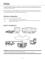
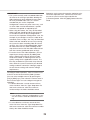
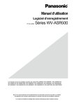
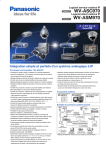
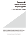
System configuration
ASC970/ASM970 System
ASM200 System
Network
9:42
100%
Mobile Client
Network camera
Server PC in which the
software is installed
Important:
• Do not use cross cables to connect the PC and each device.
• When connecting multiple system controllers, operation of this software is not guaranteed.
3
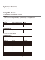
System specifications
• Camera registration: Up to 64 cameras
• User levels: 5 levels
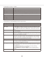
Compatible devices
The following devices are compatible with this software.
Important:
• Some functions may not work depending on the firmware version of the compatible device.
Refer to the Panasonic support website (http://panasonic.net/pss/security/support/index.html) for further
information.
Compatible client software
Model Nos.
Appears in this document as
Version
WV-ASM200
ASM200
2.00 or later
WV-ASM970
ASM970
9.0 or later
WV-ASC970
ASC970
9.0 or later
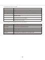
Model Nos.
Appears in this document as
Version
WJ-NT304
NT304
1.32 or later
WJ-GXE500
GXE500
1.50 or later
Compatible encoder
WJ-NT304 is only available with CH1.
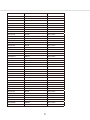
Compatible cameras
Model Nos.
Appears in this document as
Version
WV-NF284
NF284
1.64 or later
WV-NP244
NP244
1.81 or later
WV-NP1004
NP1004
1.25 or later
WV-NF302
NF302
1.60 or later
WV-NW502S
NW502S
1.80 or later
WV-NP502
NP502
1.80 or later
WV-SF539
SF539
1.40 or later
WV-SF538
SF538
1.40 or later
WV-SW559
SW559
1.40 or later
WV-SW558
SW558
1.40 or later
WV-SF548
SF548
1.40 or later
WV-SP509
SP509
1.40 or later
WV-SF549
SF549
1.40 or later
WV-SP508
SP508
1.40 or later
WV-SF336
SF336
1.80 or later
WV-SF335
SF335
1.80 or later
4
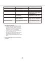
Model Nos.
Appears in this document as
Version
WV-SF332
SF332
1.80 or later
WV-SP302
SP302
1.80 or later
WV-SP305
SP305
1.80 or later
WV-SP306
SP306
1.80 or later
WV-SW352
SW352
1.80 or later
WV-SW355
SW355
1.80 or later
WV-SW395
SW395
1.80 or later
WV-SW396
SW396
1.80 or later
WV-SC385
SC385
1.80 or later
WV-SC384
SC384
1.80 or later
WV-SC386
SC386
1.80 or later
WV-ST162
ST162
1.80 or later
WV-ST165
ST165
1.80 or later
WV-SF346
SF346
1.80 or later
WV-SF342
SF342
1.80 or later
WV-SW175
SW175
1.80 or later
WV-SW172
SW172
1.80 or later
WV-SP105
SP105
1.80 or later
WV-SW314
SW314
1.80 or later
WV-SW316L
SW316L
1.80 or later
WV-SW316
SW316
1.80 or later
WV-NW964
NW964
1.64 or later
WV-NS954
NS954
1.64 or later
WV-NW502
NW502
1.80 or later
WV-SP102
SP102
1.80 or later
WV-SF132
SF132
1.80 or later
WV-SF135
SF135
1.80 or later
WV-SW152
SW152
1.80 or later
WV-SW155
SW155
1.80 or later
WV-NW484
NW484
1.62 or later
WV-NW484S
NW484S
1.62 or later
WV-NS202
NS202
1.11 or later
WV-NS202A
NS202A
2.74 or later
WV-NP304
NP304
1.61 or later
WV-SF438
SF438
1.40 or later
WV-SW458
SW458
1.40 or later
WV-SW458M
SW458M
1.40 or later
WV-SF138
SF138
1.05 or later
WV-SW158
SW158
1.05 or later
WV-SW598
SW598
1.05 or later
WV-SC588
SC588
1.05 or later
5
Features
Easy connection to IP cameras:
• Each server expandable up to 64 IP cameras
• Supports IP cameras and encoders from multiple manufacturers.
• Supports latest IP camera technology including megapixel cameras, H.264 and analytics.
Intuitive user interface:
• Intuitive user interface requires little to no training.
• Common client connects to multiple servers to create scalable networks.
Client-Server architecture:
• Server software runs on Windows Server 2012.
• Client software operates in Windows.
Mobile Apps: iPhone & iPad, Android:
Mobile Apps provides a host of client features including live view, search and playback, alarm activation and
assessment.
International support:
Language Localization - Select between English, French, German, Spanish, Italian, Russian, Chinese.
Powerful integration:
Integration with leading access control systems, retail analytics, iSCSI storage, Wireless Networking, Video
Analytics, and more.
Important:
• Some functions may not be available depending on the firmware version of the camera in use.
Standard accessories
Installation Guide���������������������������������1 pc.
Activation Key Card�����������������������������1 pc.
Important:
• This software will not work if the license is not registered. After installing the software on the PC in use, register the license.
6
Trademarks and registered trademarks
• Microsoft, Windows, Windows Server are either registered trademarks or trademarks of Microsoft
Corporation in the United States and/or other countries.
• Microsoft product screen shot(s) reprinted with permission from Microsoft Corporation.
• iPad, iPhone are registered trademarks of Apple Inc., registered in the U.S. and other countries.
• Android is a trademark of Google Inc.
• All other trademarks identified herein are the property of their respective owners.
Abbreviations
These are descriptions of the basic terms used in these operating instructions.
Microsoft® Windows Server® 2012 (64-bit) are described as Windows Server 2012.
Open software
This product uses open software subject to the licenses of Free Software Foundation such as GPL/LGPL and
others. Related conditions are applied with this software.
Make sure to access the following URL and read the information regarding licenses of GPL/LGPL and open
software before using this product.
http://security.panasonic.com/pss/security/support/oss/asr500_oss_gpl_lgpl_licens.html
Source code approved by the licenses of GPL /LGPL are publicly-released. Please note that those software are
not included in the warranty. Complying with the licenses of GPL/LGPL, Panasonic System Networks Co., Ltd.
will provide, at its own expense, the complete machine-readable code compatible with GPL/LGPL software and
its copyright declaration list to the individual or organization who has contacted Panasonic in this regard at
least for three years after the sales of this product. Consult via the inquiry page in the following site regarding
the above information including how to obtain the related source code.
http://security.panasonic.com/pss/security/support/inquiry.html
This product includes software developed by the OpenSSL Project.
Disclaimer
Note that some or all information to be recorded may be lost when too many cameras are connected and network performance beyond the specifications of this software or the PC in use is required, when the PC is overloaded by operating other programs together with this software or when unknown/unspecified problem/error
occurred.
Panasonic assumes no responsibility or liability, directly or indirectly, for any damage, loss, including recording
data loss, or inconvenience resulting from any error or failure including when recording has not been performed.
Panasonic also assumes no responsibility or liability for any error or failure caused by using a third party camera or device.
7
System installation checklist
Config (Setup) Page (see "Config (Setup) page overview" (☞ page 13))
System
• Set server for static IP address.
• Configure the system name, time, and time zone.
Storage
• Ensure all disks are selected for recording except the system drive ("C:\")
• Ensure total disk space matches the expected value.
Add IP Cameras
• Add IP cameras to the Servers.
Camera Recording (IP cameras)
• Set resolutions.
• Set frame rate.
Camera Recording (analog cameras)
• Set resolutions.
• Set frame rates.
• Disable cameras that are not connected.
Serial Port
• Set up serial port for RS-485 mechanical PTZ control.
• Set up serial port for input from serial devices.
Camera Settings
• Name camera.
• Enable onscreen display.
• Set motion mask on IP cameras (there are generally no motion windows set on a new camera).
The default motion recording schedule won't trigger recording.
• Mask motion from irrelevant objects such as moving trees.
• Create windows in relevant locations, such as doors and hallways.
• Configure quality just high enough to see relevant details.
• If supported by the cameras, set recording format to MPEG-4 or H.264 instead of JPEG for better storage.
• Watch for blue border around live video window on setup page when motion is occurring to
ensure that motion sensitivity and masking are appropriately configured.
• Configure mechanical PTZ presets.
Schedule
• Motion is recorded by default. Change any cameras to continuously record or stop recording as
needed.
• Schedule events for notification only when they are unexpected.
Users
• Add user accounts for the people who will use the system.
Trigger Inputs
• Name input triggers to be used.
• Set radio button to normally open or closed to match physical switch.
8
Config (Setup) Page (see "Config (Setup) page overview" (☞ page 13))
Alarm Outputs
• Name any alarm outputs to be used.
Notifications
• Create email profile for system health administrator.
• Create email profile for security events such as unexpected motion or input triggers.
• Create email profile for the installer.
Auto Export
• Create profile for video sources and duration to store on high-priority event.
• Insert blank CD or DVD in DVD drive.
Event Linking
• Create events to alert administrator via email of system health issues.
• Create events to record video on input triggers.
• Create events to email security administrator upon unexpected triggers or motion.
• Create event to burn CD via Auto Export profile upon event or manual activation.
• Create event to email installer when license subscription is near expiration.
Export Settings
• Save settings and license to a USB flash drive to aid the recovery process, if necessary.
9
Installing the software
Server requirements
Hardware requirements
Actual hardware requirements vary considerably based on each user's application:
• CPU requirements increase greatly when hosting multiple concurrent web clients.
• The Server application requires a maximum of 4GB, although additional memory is required for the operating system, web hosting, or any other server applications.
• The storage system is often the performance limitation because of the large amount of read and write processes. Your storage system should be capable of sustained reads/writes at least twice the maximum data
rate from all cameras. Panasonic highly recommends using RAID 5 or RAID 6 for all video storage to reduce
the likelihood of catastrophic failure.
• Enterprise-grade hard drives are highly recommended to handle constant video recording.
• The server operating system and this software should be installed on a dedicated, mirrored operating system drive.
• Servers should always be UPS-powered to avoid data corruption during power failure.
IMPORTANT:
• In regard to the time synchronization of this software, the performance of the PC clock function may generate variation in the time of the recording image. It may cause a problem in the operation. Use an NTP server
when the more accurate time & date setting is required for the system operation.
Operating system requirements
This system must be installed on Windows Server 2012. In addition:
• If automatic updating is enabled, your server might stop recording video when the operating-system
restarts.
To prevent this, disable the automatic updating.
• Anti-virus programs should scan only the operating system and this software drives. Virus scanning should
be disabled on all video storage drives to avoid large decreases in drive performance.
• Port blocking is not recommended because many edge devices use multiple or dynamic port assignment.
MAC addressing requirements
This software is licensed based on MAC addressing. Servers with teamed NICs or other arrangements that
obscure the MAC require an additional USB-based NIC to provide a licensing MAC.
Networking
For the greatest system reliability and performance, the network administrator should observe the following
best practices:
• A dedicated VLAN and NIC port for all cameras.
• A dedicated VLAN and NIC port for storage networks (if used).
• A separate VLAN and NIC for all client connections.
• Cameras and Servers should use fixed IP addresses. Clients can use DHCP.
• Camera-to-server network capacity should be twice to maximum video data rate.
• Server-to-thick-client network capacity should be 1.5 times the maximum total data rate of all simultaneously viewed cameras.
10
Software overview
License
Recording Software
Channel License: WV-ASRE501, WV-ASRE501W, WV-ASRE516, WV-ASRE516W, WV-ASRE532,
WV-ASRE532W, WV-ASRE564, WV-ASRE564W
Upgrade License: WV-ASRE571, WV-ASRE571W, WV-ASRE572, WV-ASRE572W, WV-ASRE599,
WV-ASRE599W
Update Software
Software Update License: WV-ASRM501, WV-ASRM501W, WV-ASRM516, WV-ASRM516W,
WV-ASRM532, WV-ASRM532W, WV-ASRM564, WV-ASRM564W, WV-ASRM571, WV-ASRM571W
Software Update License of Expired license: WV-ASRX501, WV-ASRX501W, WV-ASRX516,
WV-ASRX516W, WV-ASRX532, WV-ASRX532W, WV-ASRX564, WV-ASRX564W, WV-ASRX571,
WV-ASRX571W
Channel License: A license required to add channels (cameras).
Upgrade License: A license required when changing MAC address.
Software Update License: A license to enable software update.
Software Update License of Expired license: A license to enable software update when the Update License
is expired.
Logging in
All Servers are shipped with two operating system accounts:
1. Username: admin
Password: admin256
Privileges: computer administrator
2. Username: user
Password: user5710
Privileges: restricted user
Note:
• Panasonic recommends that the default passwords be changed by the operator and written and secured to
prevent unauthorized access or modifications to the system. As part of the initial configuration, Panasonic
recommends that the operator configure a new user on the Server with restricted privileges and change the
Client settings in the user operating system account to connect to the local Server via this user. See the
"Users" section of this manual for instructions on creating a new this system user.
When Servers start, they immediately start the system service, boot into the user account, and start the Client
software. Server log-in is not required to start video recording or communication with client PCs. All third-party
servers start this system service on startup, but user accounts and automatic login must be manually configured.
The user account functionality is limited to using the Client software for maximum reliability. All server maintenance tasks (such as shutting down this system service) that are not performed within the Client require logging
into the operating system's administrator account.
Each operating system user account maintains separate settings for its Client. These settings include usernames, passwords, and network addresses required for Client to access Servers. By default, both the user and
admin operating system accounts have settings that provide administrator access to the instance of the Server
running on the local computer, which is always via the localhost (127.0.0.1) IP address.
11
Panasonic recommends that all servers be configured with one system administrator account with Remote
Desktop remote access for system support.
The Server can be accessed from multiple Client, which can be running from the same computer as the Server
or from remotely networked computers. The Server has been preconfigured with one user.
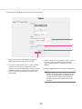
About the Client
Click the logo in the upper-right corner of the page to open the "About ASR500 Series Client" window.
1. The window lists the current version and built date.
Main pages
This system has a main operating page, as represented by the following icon:
Config (Setup) Page allows Administrators and Power Users the ability to configure systems.
12
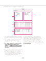
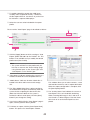
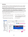
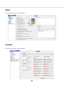
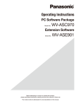
Config (Setup) page overview
w
q
Config (Setup) Page allows you to configure systems, cameras, and other devices.
qq Configuration Tree
This tree allows you to open the various configuration pages for each connected system. Each of
the pages is described in detail in the following
sections.
ww Systems
This default Config page displays systems that
have been added.
13
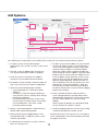
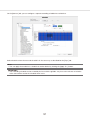
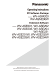
Add Systems
e
r
i
t
w
!0
!1
q
y
o
u
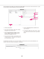
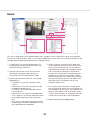
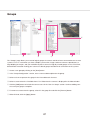
The "Add Systems" page allows you to add systems so that you can connect to them with this System.
qq To add a system, click the [New] button.
(Alternatively, you can find a system, as discussed
below.)
oo To find a system and its address on your network,
enter the IP address range in the "Find Systems"
area. The first three boxes must be the first three
elements of the IP address; the fourth and fifth
boxes are used to create a range of numbers for
the final element of the IP address. Click the [Find]
button to list all systems whose IP addresses are
in the IP address range. When the search is complete (or when you click the [Stop] button, which
replaces the [Find] button), select any of the systems to add the system to the "System List" and
populate the "Hostname/IP Address" field. You
must still enter a valid username or password to
be able to connect to the system. Click the [Apply]
button when finished.
ww The new system is added to the "System List".
The "System Information" fields are enabled.
ee Enter the system's hostname or IP address.
Contact the system administrator for details.
rr By default, the port number is 22609; change this
only if necessary for your network configuration.
tt Select one of the following login methods:
• "Use Single Sign-On" cannot be used for
ASR500.
• To require a username and password entry
every time the Client is started, select "Always
prompt for credentials".
• To automatically log in to the system every
time the Client is started, select "Use credentials entered below". Then enter a valid
Username and Password.
!!0 Enter a network location or web site where a
server configuration file is located and click the
[Import] button to load the list to the client computer. (This will not delete any systems already
added.)
Select "Import on Startup" to automatically load
the list whenever the Client is started.
yy Select a "Connection Speed". It determines the
default video multistreaming speed.
!!1 Click the [Export] button to save the server configuration file for import on another system.
uu When finished, click the [Apply] button. If the
entered information is valid, the system is automatically connected.
Connected systems in the "System List" also appear
in the "Configuration" tree. Disconnected systems do
not appear in the tree.
ii To disconnect or reconnect a system, select its
box in the "System List".
14
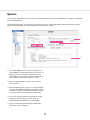
System
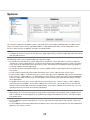
The "System" page allows you to set basic system parameters for the client application. The page is separated
into the following tabs:
The [System] tab allows you to create a name for the system, export and import settings from other systems,
import and export graphics, and manage the licensing of your system.
w
r
e
q
t
qq The "MAC Address" of the system's primary network adaptor is used to generate a license key. To
obtain a license key online, provide the system
MAC address to your dealer. Unlicensed Servers
can connect to only one IP device at a time.
ww After the dealer obtains a license key, enter the
key in this box.
ee After configuring your system, it is recommended
that you click the [Export] button to export system
settings to a USB or network drive and store it offsite for recovery from a disaster or malfunction.
rr If you ever need to restore the settings or simply
import them from another system, click the
[Import] button and apply the saved settings.
tt System information provides basic information
about the system hardware.
15
The [Date/Time] tab displays the Server's time information.
q
w
e
r
qq Select the time zone and daylight saving time
(DST) information for the server's location.
ee If the IP cameras on the network need to synchronize with a time server other than the Server,
select "Enable Override" and enter the server
address.
ww On systems with Internet access, select "Enable
Time Server" and enter a valid Internet time
server. On systems without Internet access, select
"Enable Time Server" and enter an internal time
server (see your network administrator for more
information).
rr Click the [Apply] button to save the configuration.
Note:
• Though an alert message saying that the time
zone is not recognized may be displayed on
the date and time setting screen of the PC,
this does not affect the performance of this
software.
16
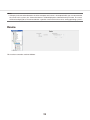
The [Network] tab displays your system's IP Address, Netmask, Gateway, and Primary DNS server.
q
w
e
r
qq Select a network connection from the "Network
Interface" drop-down list to display its information. Systems with multiple NICs have more than
one entry in the list.
ww Enter the "IP Configuration" information for the
network connection. "Gateway" and "Primary
DNS" information is required to connect with a
network time server. Click the [Apply] button.
ee Select the correct bandwidth setting to limit network traffic from the server to client computers
and iSCSI drives, and click the [Apply] button.
Note:
• This setting applies to outbound traffic from all
NICs in the system.
rr Select the "IP Reconnection" setting value in seconds. Click the [Apply] button.
17
This function cannot be used for ASR500.
18
Add IP Cameras
y
e
r
t
q
w
The "Add IP Cameras" page allows you to add IP cameras and devices to the system and configure their settings. The following features are available on the IP Cameras page:
qq The "Find IP Cameras" section scans for supported IP cameras available on the same network
that the system is connected to. If you don't see
an IP camera that you expect to see on the network, verify that the camera has been configured
and that the camera can be pinged from a command prompt. If you make any changes to an IP
camera, click the [Rescan Network] button and
check whether it is listed.
rr Enter a username, password, and IP address as
configured on the camera.
tt Click the [Apply] button to save the camera configuration.
yy To enable a camera, select its checkbox in the "IP
Camera List". The number of cameras you can
enable is subject to licensing limits.
Note:
• If you need to confirm which camera you are
installing, right-click the camera in the "IP
Camera List" or "Find IP Cameras" list to
access the camera's website and view a video
image.
The camera should now also be listed in the
"Configuration" tree.
Note:
• When camera is registered, deleted, or settings
are changed, the setting of ASM200/ASM970 is
required.
• Refer to the Operating Instructions of ASM200/
ASM970 for further information.
ww Select a camera in the "Find IP Cameras" list to
add it to the "IP Camera List".
ee Alternatively, you can manually add a camera by
clicking the [New] button and selecting the device
type as follows:
• If the appropriate manufacturer-specific driver
is shown in the list, select it.
• If that is not available and the device is ONVIFcompliant, select the ONVIF driver. (The level
of integration can vary by manufacturer or
model.)
• RTSP-compliant cameras can stream video
but not motion detection or camera configuration data.
IMPORTANT:
• In the process of camera registration, this software configures the NTP setting of the camera to
be registered. Once the NTP setting is configured
by this software, do not manually change the NTP
setting of the camera.
19
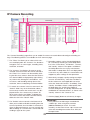
IP Camera Recording
q
w
y
e
y
r
t
u
The "Camera Recording" page allows you to enable IP cameras to record video and configure recording settings. The following features are available on the IP Cameras page:
qq The "Filters" list allows you to select which cameras are displayed in the "Cameras" list, based on
categories such as camera type, recording status,
resolution, and more.
tt Recording settings can be changed individually
for a camera by selecting any of the drop-down
lists in the "Frame Rate", "Resolution", "Format",
and "Quality" columns. The options available in
each drop-down list can vary by manufacturer
and model. If a drop-down list is not displayed for
a camera in any of the fields, the camera does not
support any other settings for that parameter.
ww The "Cameras" list displays all cameras on the
selected server that match the criteria selected in
the "Filters" list. Cameras can be sorted by clicking the title of any column. Several of the columns
can also be hidden or displayed by right-clicking
any column title, although the checkboxes, camera names, and recording settings (frame rate,
resolution, format, and quality) cannot be hidden.
yy Alternatively, to apply a quality setting to multiple
cameras simultaneously, select the checkbox in
the first column for each applicable camera (or
select the "Select All Cameras" checkbox), select
"Quality" checkbox, choose a video quality from
the drop-down list, and click the [Apply to
Cameras Grid] button. The quality should now be
modified for all selected cameras, as shown in the
"Quality" column in the "Cameras" list.
ee To search for a camera in the list, enter text in the
"Search" field. If any of the information about a
camera entry matches the search text in any displayed column, the camera entry is shown; all
other camera entries are hidden. To display the
rest of the cameras that match the Filter criteria,
delete the text in the "Search" field.
uu Click the [Apply] button to activate any changes.
IMPORTANT:
• It may take time to find images recorded with
"JPEG/1 fps" when using client software
(ASM200/ASM970) to search. To search
smoothly, set the frame rate to 2 fps or more and
select the recording format other than JPEG, for
example H.264.
rr The "Enable" column contains check boxes that
allow you to enable or disable recording from that
camera. By default, the check box is selected if a
signal is detected; however, you can manually disable recording on a camera that is connected and
sending a signal to the system.
20
Analog Camera Recording
This function cannot be used for ASR500.
21
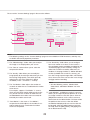
Camera Settings
w
e
r
t
y
q
u
The "Camera Settings" page is where you configure the individual IP and analog camera settings such as camera name, onscreen display, "PTZ" settings, video settings, recording quality and motion and video masks. This
page is identical whether you are configuring an IP or an analog camera, but certain features might be unavailable depending on the type of camera you are configuring. The following features are available on the "Camera
Settings" page:
Note:
• Note that the settings of this program and the target camera may have different meanings. For example, if
you set the JPEG image (Quality) to "1" in this program, "9" (Low quality) will be set to the camera.
For example, you might want to limit video quality
for remote clients while displaying the same camera in high quality for local clients. Each stream
can have custom recording schedules, storage
rules, and event triggers.
qq Use the "Configuration" tree to select the camera
that you want to configure.
ww A live view of the selected camera is displayed.
ee Basic information about the camera is listed.
rr The "Camera Name" field allows you to change
the name of the camera as it appears throughout
this system.
tt The "On-Screen Display" section allows you to
select the information displayed in the camera's
window, the location in the window where it is displayed, and the font of the displayed text. Select
one or more items to display, and then select the
position of the items. Click the [Font] button to
change the appearance of the text. Click the
[Apply] button to save the configuration.
Each camera has a different limit to the number of
streams that can be added. The drop-down list
shows the next context (stream) number available;
click the [Add Stream] button to name the new
context. You can then adjust the quality settings
for the stream, or modify the "Crop Window" section (☞ page 23) to create a region of interest. The
new stream is listed in the "Configuration" tree as
a child of the main camera. To delete a stream,
select it in the tree and click the [Delete Stream]
button.
uu See the "PTZ configuration" section of this manual
for details about the "PTZ" section of the "Camera
Settings" page.
yy The "Multistreaming" feature appears only for
cameras that support multistreaming. It allows
you to create streams with different video settings
or regions of interest from a single camera view.
22
The rest of the "Camera Settings" page is discussed as follows.
i
o
!0
!1
!2
!3
!6
!4
!5
!6
!5
Note:
• The following settings on the "Camera Settings" page are not available on RTSP interfaces, and they vary
on ONVIF and certain proprietary interfaces.
!!3 The "Sensitivity" slider allows you to configure
how much motion must occur in the camera's
view to trigger motion recording (if enabled on the
"Schedule" page). A low sensitivity setting can
reduce false motion created by video noise or
shadows. If the page includes a "Motion Window"
section (available with certain IP cameras), you
can also change a percentage slider, which determines how much of the camera view must change
to trigger motion recording.
ii The "Video Settings" sliders allow you to adjust
the image as it is displayed on your screen.
oo The "Format" section allows you to select the
compression format.
!!0 The "Quality" slider allows you to modify the
image quality by increasing or decreasing its size.
Decreasing image quality saves disk space by
reducing the size of the video that's being
recorded. (1:Low <- 5:Normal -> 10:Fine)
Note:
• See the following section, "Motion Mask,
Video Mask, and Motion Window" for more
details.
!!1 The "Pre Motion" slider adjusts the number of
seconds of video that are saved before the motion
event occurs.
For example, suppose "Pre Motion" is set to 5;
when you play back motion video from that camera, you will see five seconds of video that was
recorded before the motion event occurred, followed by the motion event itself.
!!4 "Crop Window", available on certain IP cameras,
allows you to crop unimportant portions of a camera image in order to save disk space. Click the
[Edit] button and then use the mouse cursor to
draw a box on the video window. This box will be
the portion of the camera's view that will be
recorded and displayed (the rest of the view will
be ignored). Click the [Apply] button to activate
the crop; click the [Edit], [Clear], and [Apply] button to deactivate the crop.
!!2 "Post Motion" is the same as "Pre Motion",
except that the slider adjusts the number of seconds of video that are saved after the motion
event has completed.
23
!!5 The [Apply Defaults] buttons restore factory settings to their respective sections. One [Apply
Defaults] button restores the "Video Settings",
and the other restores the "Record Settings".
!!6 See the following section "Motion Mask, Video
Mask, and Motion Window" for more information
about those portions of the "Camera Settings"
page.
IMPORTANT:
• Many IP camera settings that are not available in
this system can be accessed through the camera's web page. To view an IP camera's web
page, click the hyperlink in the "IP Address" field.
If you don't see a hyperlink beside the "IP
Address" field, it could be for one of two reasons:
A. You are not logged in to the operating system
with administrative privileges. You must log in
to operating system account with administrative privileges to access the hyperlink.
B. Your client computer is not located on the
same IP subnet as the IP camera. This could
occur if you are using the client from a home
computer to access a server at your office, for
example. This restriction should cause few
issues because camera website settings are
typically changed only during initial configuration.
Note:
• When camera is registered, deleted, or settings
are changed, the setting of ASM200/ASM970 is
required.
• Refer to the Operating Instructions of ASM200/
ASM970 for further information.
24
Motion Mask, Video Mask, and Motion Window
The following types of masks can be created on cameras connected to this system:
• A "Motion Mask" is an area of a video window where motion is ignored
• A "Motion Window" is an area of a video window where motion is monitored (and the remainder of the
screen is essentially masked).
• A "Video Mask" is used to block an area of a camera's view so that it cannot be seen onscreen in live or
recorded video.
Note:
• The type of mask available varies by camera.
A motion mask reduces unwanted recording by ignoring motion events that occur in certain areas of an image.
For example, if a camera is pointed at a room that has a moving ceiling fan in the field of view, you can avoid
continuous motion recording by masking out the fan while still recording motion that occurs in the rest of the
camera's field of view.
"Motion Mask" save storage space, extend recording time, and make it easier to visually see motion events on
the video timeline. A motion window is simply the opposite of a motion mask.
To create a motion window, complete the following steps:
rr Click the [Apply] button to enable the motion
mask or motion window.
qq Press the [Edit] button shown in the "Motion
Window" of the "Camera Settings" page.
To create a motion mask, complete the following
steps:
ww To add a "Motion Window", press the [Add] button.
The blue rectangle will be displayed on the live
video from the camera.
Draw masks on the live video.
Adjust the "Sensitivity" and "Percentage" by moving each slider.
Select "Include" or "Exclude".
Repeat step 2 until desired area is obtained.
qq Press the [Edit] button shown in the "Motion
Mask" of the "Camera Settings" page.
ww To add a "Motion Mask" , click on the live video
from the camera.
The blue rectangle will be displayed.
ee Click the [Apply] button to enable the motion
mask.
ee To delete a mask, click the masks tab first, and
press the [Remove] button.
To delete a motion mask or window, click the [Edit],
[Clear], and [Apply] button.
A "Video Mask" is used to block an area of a camera's view so that it cannot be seen onscreen in live
or recorded video.
This can be useful if you don't want system users to
see a combination safe or keypad that is in the camera's field of view, for example.
25
To create a video mask, complete the following steps:
qq On the "Camera Settings" page, click the [Edit]
button in the "Video Mask" section. This displays
a yellow grid over the live video from the camera.
ww Draw the mask directly in the grid by left-clicking
while dragging the cursor over the area of the grid
you want to mask. A green rectangle indicates the
masked area.
ee Click the [Apply] button. The yellow grid disappears and green rectangle is replaced by a solid
gray rectangle. This area is now masked from
both live and recorded video. To clear the mask,
click the [Clear] button.
26
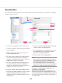
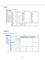
Serial Profiles
The "Serial Profiles" page enables the Server to integrate with serial data devices such as point-of-sale (POS)
and bank machine systems.
q
o
e
r
t
y
u
w
i
!0
ii The [Line Masks] and [String Replacements] tabs
are discussed on the following page.
qq To view an existing profile, select it from the list.
ww To add a new profile, click the [New] button below
the list of profiles.
oo The "Data Retention" section allows you to select
the number of days that serial data is stored
before it is automatically deleted.
ee Enter a unique name in the "Name" field in the
"Profile Configuration" box.
!!0 When finished, click the [Apply] button.
rr The "SOT marker" (Start of Transaction) tells this
system when the transaction has started. For
example, you could enter the first line shown on a
receipt. This entry is case-sensitive.
Note:
• You can require case sensitivity for all strings or
all key words by selecting the appropriate "Case
Sensitive" option under each list. To enter the
ESC (0x1b) ASCII character as the SOT, EOT,
mask, or key word, enter "/x1b" in the appropriate
field. CR, LF, or 80 characters terminates a line.
tt The "EOT marker" (End of Transaction) tells this
system when the transaction has ended. For
example, you could enter the last line shown on a
receipt. This entry is case-sensitive.
The steps 7, 8, and 9 will be enabled only when
changing the existing profile.
You have now created the new serial profile. If you
entered any data in the "Event Keywords" box, you
must link the profile to the appropriate Action through
the "Event Linking" page, selecting "Serial Profile" as
the "Event Type".
yy The [Font...] button allows you to select the font.
uu The [Event Keywords] tab allows you to set alarms
that will be triggered through key words on a
receipt after you link the profile through the Event
Linking system.
27
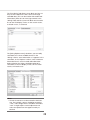
The [Line Masks] tab allows you to black out lines so
they are not visible on the live camera or through
recorded data. (This can be used to hide credit card
information.) Enter one or more signal words in the
"String" field, and the system will black out the entire
line on the live display screen, on the search results,
or in both cases, as selected.
The [String Replacements] tab allows you to modify
serial data to a human-readable format. In the
"String" column, enter information as it appears in the
serial data; in the "Replace" column, enter substitute
information that is easier to read and understand.
Select whether the strings should be replaced in
serial data on the live display screen, on the search
results, or in both cases.
Note:
• Certain characters must be entered in ASCII format. For example, spaces should be entered as
"/x20," and carriage returns should be entered as
"x0A." It might require several adjustments to
make the replacement text appear exactly as
desired.
28
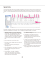
Serial Ports
The "Serial Ports" page allows you to configure serial ports on this system so that they can be used to communicate with serial devices such as POS terminals or pan-tilt-zoom (PTZ) cameras. There are two "Serial Ports"
sections — one for standard UART (Universal Asynchronous Receiver/Transmitter) and one for serial ports over
IP.
q
w
e
r
t
y
u
i
o
!0
For a UART serial port, connect the wires to the serial port and then configure the port. The system automatically detects and displays the serial ports. You can configure the following settings on each port:
uu The "Max Line Length" is 80 by default. Generally,
you should not change this.
qq Select the intended use of the serial port from the
drop-down list in the "Use" column. The choices
are "Unused", "PTZ" (pan/tilt/zoom), "POS" (point
of sale), "ATM" (automatic teller machine), or
"Access Ctrl". Generally, the POS mode is used to
record transactions at a cash register. By default,
the last serial port listed is the built-in RS-485
port.
ii "Line Ending" is the number of characters
received before an end-of-line character is
inserted automatically. This prevents lines from
becoming extremely large.
oo "Timeout" is the number of seconds after which
an end-of-line character is entered if a serial
device has not sent text. This is useful if the serial
data does not have an end-of-line character but it
hasn't reached the number of characters entered
in "Line Ending".
ww Enter a unique name in the "Name" field.
ee The "Status" column displays the current status of
the serial port.
rr The "Port" is automatically selected by the
Operating System.
!!0 When you are finished, save the settings by clicking the [Apply] button at the bottom of the list.
tt The "Profile/Protocol" column allows you to select
one of the profiles configured on the "Serial
Profile" page.
yy The "Baud Rate", "Data Bits", "Stop Bits",
"Parity", and "Flow Control" must match the
device you are connecting to. See the device's
documentation for more information.
29
The "IP" section is explained as follows.
q
w
e
r
t
y
u
i
o
!0
!1
!1
!2
For serial over IP, you must add the port by clicking the [New] button; the system does not automatically detect
and list IP serial ports.
You can configure the following settings on each port:
!!0 "Timeout" is the number of seconds after which
an end-of-line character is entered if a serial
device has not sent text. This is useful if the serial
data does not have an end-of-line character but it
hasn't reached the number of characters entered
in "Line Ending".
qq Select the intended use of the port ("Unused",
"POS", "ATM", or "Access Ctrl").
ww Enter a unique and descriptive name for the port.
ee The "Status" column displays whether the port is
currently connected.
!!1 To delete an IP port, choose its "Select" checkbox
and click the [Delete] button.
rr Select a profile from the drop-down list. "Profile",
which are created on the "Serial Profiles" page,
are used to filter an incoming serial string to isolate useful information.
!!2 When you are finished, save the settings by clicking the [Apply] button at the bottom of the list.
tt Select the transport type as defined by the source
device manufacturer's documentation.
yy Enter the IP address of the source device.
uu Enter the TCP port of the source device as
defined by the device manufacturer's documentation.
ii Enter the maximum number of characters per line
sent by the source device. If you are unsure of the
correct value, use the default setting of 80. Setting
this number too low could result in missing characters at the end of certain lines.
oo "Line Ending" is the number of characters
received before an end-of-line character is
inserted automatically. This prevents lines from
becoming extremely large.
30
PTZ configuration
This section discusses the "PTZ" section of the "Camera Settings" page, which allows you to identify a camera
as a PTZ device and configure PTZ presets.
q
w
e
t
r
qq Select the camera's COM port from the "Serial
Port" drop-down list. This port is configured on
the "Serial Ports" page.
ww Select the camera's Address as configured on the
camera hardware. (The protocol is automatically
displayed based on the Serial Port selected.)
ee The [Settings] button under "PTZ" opens the "PTZ
Settings" window, which is described on the following page.
rr To enable digital PTZ/Fisheye functions, select the
"Enable" checkbox. This is available even if the
camera is not mechanically capable of PTZ/
Fisheye functions.
tt The [Settings] button under "Digital PTZ/Fisheye"
opens the "Digital PTZ Settings" window, which is
described after the Analog PTZ Control description.
Note:
• When you create a PTZ preset, it is initially named
"New preset_1" by default. Then, if a PTZ preset
named "New preset_1" exists, the next PTZ preset is named "New preset_2". However, if you
create a new digital preset, it will also be named
"New preset_1", regardless of whether there is
already a PTZ preset with that name. To avoid
having both a PTZ preset and a digital preset with
the same name, make sure you enter a unique
name for each preset that you create.
31
PTZ presets can be configured by clicking the left [Settings] button on the "Camera Settings" page.
y
u
q
r
t
w
o
i
e
!0
ii "Resume time" is the number of seconds that certain PTZ functions (such as a tour, a linked event,
or a soft trigger) can resume after a user manually
controls PTZ functions. Dwell time is the amount
of time that the camera stays on each preset.
qq Click the [New] button.
ww Use the buttons of "Pan/Tilt" to point the camera
at the desired preset location. If the camera
moves too quickly or too slowly, move the
"Speed" slider left (slower) or right (faster).
oo Select "Enable" to activate the tour.
ee Adjust the "Zoom" settings as desired.
!!0 Select [Apply] button to complete the process.
rr Enter a name or number for the preset in the
"Name" field.
tt Click the [Apply] button to enable the preset.
yy The preset is listed under "Presets". The total
number of presets configured and supported is
shown under the list.
uu To create a "Preset Tour", select a preset from the
"Presets" list and click [Add>>] button to show it
in the "Preset Tour" list.
Repeat for each remaining preset that you want to
include in the tour. You can re-order the presets in
the Preset Tour list by clicking and dragging them
to the desired place in the tour. To delete a preset
from the tour, select it in the "Preset Tour" list and
click the [<<Remove] button. A preset can be
included multiple times in the tour.
32
Digital PTZ presets can be configured by clicking the [Settings] button in the "Digital PTZ/Fisheye" block on the
"Camera Settings" page.
yy Select a "Mode" for cameras with this systemsupported fisheye lenses. If you select
"ImmerVision", additional drop-down lists appear
that allow you to select a model and mounting
options.
y
t
e
r
q
w
qq Use the buttons of "Pan/Tilt" to point the camera
at the desired preset location. If the camera
moves too quickly or too slowly, move the
"Speed" slider left (slower) or right (faster).
ww Adjust the "Zoom" setting as desired.
ee Click the [New] button to enable the preset.
rr Enter a name or number for the preset in the
"Name" field.
tt The preset is listed under "Presets". The total
number of presets configured and supported is
shown under the list.
33
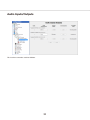
Audio Inputs/Outputs
This function cannot be used for ASR500.
34
Trigger Inputs
w
e
q
r
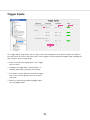
The "Trigger Inputs" page allows you to assign a name and configuration to the discrete inputs on hybrid systems and certain IP cameras with alarm inputs. These triggers can be configured to trigger video recording or a
relay using the "Event Linking" page.
qq Enter a name for each trigger input in the "Trigger
Name" column.
ww Configure the trigger input's "Normal State" as
Normally Open (NO) or Normally Closed (NC).
ee The "Status" column indicates whether the trigger
input is in its normal (green) state or in its alarm
(red) state.
rr When you are finished configuring trigger inputs,
click the [Apply] button.
35
Alarm Outputs
w
e
q
r
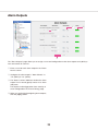
The "Alarm Outputs" page allows you to assign a name and configuration to the alarm outputs on hybrid systems and certain IP cameras.
qq Enter a name for each alarm output in the "Alarm
Name" column.
ww Configure the alarm output's "Normal State" as
"Hi" (5VDC) or "Lo" (0VDC).
ee The "Status" column indicates whether the alarm
output is in its normal (green) state or in its alarm
(red) state.
The output can be triggered to alarm state by an
event configured on the "Event Linking" page.
rr When you are finished configuring alarm outputs,
click the [Apply] button.
36
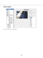
Video Output
This function cannot be used for ASR500.
37
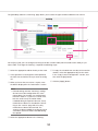
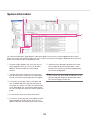
Storage
The "Storage" page allows you to configure the system's hard drives for video storage and monitor the health
of drives and RAID arrays. The following tabs are available on the "Storage" page:
• The [Drive] tab displays all the installed drives, their capacity, available storage space, and status.
• The [Hardware] tab allows you to monitor attributes of each hard drive and RAID controller.
The following features are available on the [Drive] tab:
y
q
w
e
t
r
i
u
qq The system drive ("C:\") is reserved for this system software and operating system and is not
enabled for video storage. Do not record video to
this drive.
tt "Used Space" displays how much of the hard
drive capacity is currently full.
yy "Status" displays the current state of the hard
drive.
ww The storage drives are listed below the system
drive.
uu "Oldest Content" indicates the age of the oldest
video recorded on this system. This does not
affect cameras added in the "Expiration
Configuration" section.
ee To enable a drive for video storage, select its
"Enabled" box.
rr To adjust the maximum amount of drive space
that can be used for data storage, adjust the
"Video Space" slider for each storage drive.
ii "Expiration Configuration" allows you to set minimum or maximum time periods for video from
each camera to be stored. For example, you could
configure one camera's video to be stored for at
least 30 days before it is deleted, and another
camera's to be deleted after no more than 7 days.
See the following IMPORTANT before using this
feature.
Note:
• Performance can decrease if you set the
"Video Space" slider greater than 85 %.
38
Repeat for each camera that requires expiration rules.
To remove expiration rules, select one or more camera names in the list on the right and click the
[<<Remove] button. Click the [Apply] button when finished.
IMPORTANT:
• The system normally retains recorded video from
all cameras for as long as possible, deleting the
oldest video only when required to create room
for newly recorded video. Thus, it is recommended that you use the "Expiration
Configuration" feature only when necessary, such
as when video must be deleted after a specific
maximum time period as required by law.
• When using the feature, the "Days of Recorded
Video" indicator should be higher than the greatest number of minimum days configured for a
camera in the "Expiration Configuration" area. For
example, if you configure a camera's video to be
stored for at least 30 days, the "Days of Recorded
Video" indicator should be at least 30 (assuming
the system has been recording video for at least
30 days). If the "Days of Recorded Video" indicator were lower than 30, video recording would
stop for that camera until the oldest video stored
from that camera got deleted (after 30 days).
• To resolve issues with video expiration, you can
expand your storage capacity by adding hard
drives, reducing the minimum time that video
needs to be stored, or reducing frame rates or
quality settings for the applicable cameras. The
best way to determine your needs is by trial and
error; allow the system to record at your desired
settings and then monitor the "Storage" page to
ensure that the settings will meet the storage
requirements.
To configure video expiration, select a camera name
in the list on the left and click the [Add>>] button.
(You can select multiple cameras by pressing the
[Ctrl] or [Shift] keys.) Then select the camera name in
the list on the right. You can configure two types of
expiration:
• To delete video after a certain amount of time,
select "At Most" from the "Type" drop-down list
and use the arrows to select the maximum
number of days the video should be stored.
Note:
• If an "At Most" setting is configured for a camera, the camera cannot be selected for archiving.
• To save video for a minimum amount of time,
select "At Least" from the "Type" drop-down list
and use the arrows to select the minimum number
of days the video should be stored.
39
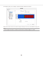
The following features are available on the [Hardware] tab:
w
q
e
r
If a drive or controller is in an alarm condition, it is
highlighted in red in the "Storage Hardware" list.
Alarm conditions can include a rebuilding array, high
drive temperature, drive verification failure, drive
removal, new drive, and more. You can configure a
notification of a drive alarm using the "Event Linking"
feature (see the "Event Linking" section of this manual
for more information).
qq The "Storage Hardware" section lists all the RAID
controllers and hard drives installed in the system.
ww The "Properties" section lists properties of the
controller or drive selected in the "Storage
Hardware" list.
ee The "SMART Attributes" list displays the current
values and operating threshold of various
attributes, as provided by the hard drive manufacturer. This section is shown for informational purposes only.
rr The "Thresholds" section allows you to modify the
temperature thresholds for a hard drive. To do
this, click the [New] button, select a hard drive
from the "Device" drop-down list, and enter a
minimum temperature and maximum temperature.
Click the [Apply] button when finished.
40
Notifications
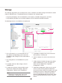
The "Notifications" page allows you to configure an e-mail server and message profile that will send an email
message when an event occurs. To configure events that cause an email notification to be sent using these
email settings, see the "Event Linking" section of this manual.
The "Notifications" page is separated into three tabs: [E-mail Message Profiles] [E-mail Servers], and [Web
Server].
w
e
r
t
y
u
q
o
i
The [E-mail Message Profiles] tab allows you to configure email notification content and recipients.
yy Enter a Subject and Message information that
should appear in the email notification. You can
automatically insert camera names using the
bracketed tag {source} and the date and time
using {date format=%H:%M:%S}. You can also
include a link to the video {weblink}, serial information {serial}, the MAC address {licensed mac},
and more (see the image above for a syntax sample).
qq Click the [New] button.
ww Enter a brief description in the "Profile
Description" field. This description will also appear
in the "Action Target" field on the "Event Linking"
page.
ee To reduce the number of email notifications sent,
select the minimum number of seconds between
notifications from the "Send Rate Limit" box. This
can be useful if you receive a large number of
repeated messages about certain events. For
example, if you configure a notification every time
a motion event occurs, a thunderstorm at night
could trigger thousands of emails over a short
period of time. Limiting notifications about the
motion events to a maximum of one every 15 or
30 minutes (900 or 1800 seconds) could drastically reduce unnecessary emails.
uu Select "Attach Preview" to attach a brief video clip
(in .MOV format) or image of the notified event.
The preview will be a video clip instead of a single
image only if the camera is streaming in H.264 or
MPEG-4 format.
ii Click the [Add/Apply] button to add the message
profile to the list of profiles.
Note:
• The [Apply] button may not become active
when a destination address is added after
selecting an already created profile In this
case, it will become active by editing the subject or body.
rr Enter the e-mail address of the person the email is
coming from.
tt Enter the e-mail addresses of the recipients.
oo You can test the profile by selecting it from the list
and clicking the [Test Profile] button.
41
The [E-mail Servers] tab allows you configure the outgoing SMTP mail server that sends email from this system.
This information can be provided by the network administrator.
w
e
y
r
t
q
tt Click the [Add/Apply] button to add the email
server to the list.
qq Click the [New] button.
ww In the "Server Description" field, enter a unique,
descriptive name of email server.
yy To change the order of the email servers, select a
server from the list and then click the up or down
button.
ee In the "Outgoing Mail Server (SMTP)" section,
enter the address and port number (25 is the
default) of the outgoing mail server.
rr If your email server requires authentication, enter
a valid "Username", "Password" and "Confirm" in
the "Authentication" section.
The [Web Server] tab allows you to enter the IP address of the web server so that email notifications can
include a direct link to video associated with a notification.
42
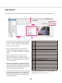
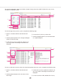
Auto Export
"Auto Export" quickly exports video from specified inputs to a CD, DVD, hard drives, or removable drives.
w
t
e
r
q
y
u
i
qq If you want to create a profile that can be used on
the "Event Linking" page, click the [New] button.
Otherwise, skip to step 10 on the following page.
%a
%A
%b
%B
%c
%d
%H
%I
%j
%m
%M
%p
%S
%U
%w
%W
%x
%X
%y
%Y
%Z
%%
ww Enter a Name for the profile.
ee Select a "Minutes Before" value, which is the
amount of video that occurred before the "Auto
Export" was started that should be included in the
export.
rr Select a "Minutes After" value, which is the
amount of video that occurs after the "Auto
Export" was started that should be included in the
export. This can be useful when an event of interest is still occurring.
tt Select the destination of the export files from the
"Export Path" drop-down list. All local Windows
drives, and USB drives should be listed. (Windows
shared directories are not listed.) The correct file
extension will be added automatically.
weekday abbrev
weekday name
month abbrev
month name
full date/time
day of month
hour (24h format)
hour (12h format)
day of year (001-366)
month (01-12)
minute
AM/PM
second
week of year (start Su)
day of week (Su=0, Mo=1)
week of year (start Mo)
date (xx/xx/xx)
time (xx:xx:xx)
last 2 digits of year
year (20xx)
time zone abbrev.
percent symbol
For example, you could enter {date format = "video
automatically exported on %x at %X"} or simply
{date format = "%H, %M, %S, %x"}.
yy If you choose a drive, enter a name for the drive in
the "Export Name" field. If you want to generate
different automated names for each export, you
can enter {date format} and any combination of
the following variables:
43
uu To enable export files greater than 4GB (up to
137GB), select "Export PS file only". Otherwise,
the file export will be in .exe format. A .ps file must
be viewed in a separate video player.
ii Select the cameras to be included in the export
profile.
The rest of the "Auto Export" page is described as follows.
o
!0
!5
!1
!2
!3
!4
oo Click the [Apply] button to finish creating an "Auto
Export" profile and add it to the "Profiles" list. This
button is not available until you modify the default
profile name (New Profile).
Note:
• The system will NOT use the profile until you
link it to an event on the "Event Linking" page
using "Button Input" as the "Event Type" and
"Auto Export" as the "Action Type".
!!0 "Drive Status" indicates whether the system has a
writable CD/DVD drive and compatible formats.
!!1 "Media Status" indicates whether a blank disc is
loaded in the drive and its format and storage
size.
!!2 The "Eject Media When Done" option configures
the CD/DVD drive to open automatically when the
system finishes exporting the data to the disc.
(Note that if the front door on the system is
latched, the drive cannot open.) Click the [Save]
button if you change the setting.
This window allows you to select cameras, a start
and end date and time, and an export destination.
When the export configuration is complete, click
the [Start Export] button.
!!5 The "Activity Status" box indicates the status of
Auto Export. This can include Idle, Gathering
Video, Creating ISO Image, In Use, and so on. It
also contains a "Write Progress" bar that shows
how much of an active Auto Export has completed.
!!3 If you insert a disk while the "Auto Export" page is
open, click the [Refresh Status] button.
!!4 To initiate an export, click the [Auto Export Now!]
button. This opens the "Auto Export" window.
44
Event Linking
w
e
r
q
t
i
y
u
o
The "Event Linking" page allows you to connect different types of events, such as the activation of an input trigger, to an action, such as recording video or triggering an alarm. Event Linking provides quicker searches for
specific event types. For example, you might normally search for motion video captured on a camera pointed
toward a door; however, if the door has a sensor, you could improve your search by looking for video recorded
whenever the door opened by linking that event with video recording.
You can see how it works by looking at the lists from left to right below the main Event List, as shown in the figure above.
When the specified "Event Type" w occurs on an associated "Event Source" e, "Action Type" r is triggered
on an "Action Target" t. These events are then stored in a database (if "Log" is selected in the "Event List") to
provide easy search capabilities. To create a new event, complete the following steps:
qq Click the [New] button to add the event to the
"Event List".
yy "Pre Trigger" allows you to store buffered data
that was captured up to 100 seconds before the
event occurred.
This feature can be used only with certain Event
Types. Very large Pre Trigger can negative impact
system performance.
ww Select the "Event Type".
ee Select the "Event Source".
rr Select the "Action Type".
uu "Post Trigger" continues the Action Type for up to
100 seconds of video after the event concludes.
tt Select the "Action Target".
ii Click the [Apply] button to save all changes to the
selected event.
Note:
• See the charts on the following pages for information about available Event Types, Event Sources,
Action Types, and Action Targets.
oo The "Log Settings" field determines how long the
event will be stored in the Event database, from
zero to 365 days.
45
The following Event Types are available:
Event Type
Description
Video Motion
Camera detects motion.
Video Loss
Analog video signal is disconnected.
Input Trigger
Discrete input on hybrid server or IP camera with alarm input is activated.
Serial Port
Key word entered on "Serial Profile" page is detected on a pre-selected port.
Serial Profile
Key word is detected on any Serial Port with that profile.
Health
Detected problem involving the health of the Server hardware.
IP Camera Connection
Network can't connect to the IP Camera.
Soft Trigger
Signal sent from the client to the server.
Time Trigger
Time of day or day of week reached.
Analytics
Video analytics event detected.
The Event Source list varies depending on the Event Type selected:
Event Type Selected
Event Source
Video Motion
Any of the cameras connected to the Server.
Video Loss
Any analog camera connected to the Server.
Input Trigger
Any input trigger on the back of the server or IP camera connected to the server.
The system defaults to a device and input number, but these can be customized
on the "Trigger Input" page. See the "Trigger Inputs" section of this manual for
details.
Serial Port
Any of the serial ports configured on the server. See the "Serial Ports" section of
this manual for details.
Serial Profile
Any of the serial profiles you have configured. You can select all key words associated with a serial profile by selecting the profile name, or you can select an individual key word configured in the profile.
Health
Includes failures or temperature problems on a device; problems with storage
configuration; subscription expiration; video throttling alarms; alarms related to
parameters monitored on the [Hardware Monitoring] tab on the "System" page;
failed connection to shared network drive for archiving.
IP Camera Connection
Any of the IP cameras connected to the Server.
Soft Trigger
Select New to create a new soft trigger with a default name. Click the [Edit] button to name it, or click the [Delete] button to remove it. You can also select any of
the preconfigured soft triggers that are listed.
Time Trigger
Select New to open a window. Name the time trigger, select a start and end time
(Client Time or Server Time), and select the days of the week when the selected
action should occur.
(For example, you could perform an Auto Export at 2:00 every morning.)
Click the [Apply] button to save the configuration.
Click the [Edit] button to change Time Triggers, or click the [Delete] button to
remove it.
Analytics
A list of video analytics events (configured through the analytics provider's interface).
46
The following Action Types are available:
Action Type
Description
None
No action will be performed. The event will be logged in the Event Database.
Record Video
Video will be recorded.
Record Audio
Audio will be recorded.
Output Trigger
A wired output trigger on the back of the server or IP camera will be activated.
Output Video 1
The analog monitor will switch to a full-screen view of the selected camera.
Notify
An email notification will be sent according to profile created on the
"Notifications" page.
Auto Export
Data will be saved to a CD/DVD based on an Auto Export profile. See the "Auto
Export" section of this manual for details.
PTZ Preset
The camera will be pointed in a specific direction. See the "Camera Settings"
section of this manual for details.
The Action Target list varies depending on the Action Type selected:
Action Type Selected
Action Target
None
No Action Target available.
Record Video
Any of the cameras connected to the Server.
Record Audio
Any of the audio inputs connected to the Server.
Output Trigger
Any output trigger on the back of the Server or IP cameras.
Output Video 1
Any of the analog cameras connected to the Server.
Notify
Any of the profiles that configured on the "Notifications" page.
Auto Export
Any of the profiles that configured on the "Auto Export" page.
PTZ Preset
Any of the presets associated with the camera on the "Camera Settings" page.
47
Event Monitoring
The "Event Monitoring" page allows you to configure this system to react to events that take place on connected servers. First, you must create and define Event Monitoring Profiles, which are a set of actions (such as
displaying live video or triggering a sound) that are triggered by events (such as motion or triggered inputs).
w
e
r
q
t
y
u
i
qq To create a new profile, click the [New] button in
the "Profiles" section.
yy The "Action Type" list allows you to select an
action that will occur when the selected "Event
Type" occurs on the selected "Event Source".
When you select an Action Type, a list of options
is displayed in the "Action Target" list. Following
are the available Action Type options and their
associated Action Target options:
ww Enter a name and description for the profile.
ee Select "Show Event Monitor List" to automatically
display a window when one or more monitored
events occur.
Note:
• The list of "Action Type" varies based on
whether the profile is a "Video Panel" or
"View".
rr Select the type of profile you would like to create:
• A "Video Panel" profile can display a single
camera when a specific event type occurs.
• A "View" profile displays a preconfigured view
when a specific event type occurs.
tt Add an event to monitor. This works in a similar
way as the Event Linking discussed in the "Event
Linking" section of this manual. Select an "Event
Type", "Event Source", "Action Type", and "Action
Target". The options listed in "Event Source" vary
depending on which Event Type (such as triggers,
serial ports, and serial profiles) is selected and
how it is configured. For more information, see the
sections of "Config (Setup) Page Overview" chapter that are related to the desired Event Type.
48
Action Type
Description
Action Target Options
Log (Video Panel or View)
A notification of the event is saved
in the system log file.
None
Play Sound (Video Panel or View) A sound is played.
A list of sounds.
Switch Video (Video Panel)
Video from a camera is displayed.
All cameras enabled on all connected
systems (or on the system selected
from the drop-down list)
Digital Preset (Video Panel)
A PTZ preset configured on a cam- All PTZ presets configured on all conera is displayed.
nected systems (or on the system
selected from the drop-down list)
Switch View (View)
A single view is displayed until a
specific event occurs.
Any view configured on the client
computer. The view is automatically
displayed when the event occurs.
Switch View Tour (View)
A tour is displayed until a specific
event occurs.
Any tour configured on the client
computer. The tour is automatically
displayed when the event occurs.
uu If you selected "Show Event Monitor List", three
more options are activated:
• "Timeout" allows you to determine how long,
in seconds, an event is shown in the "Event
Monitor List". If you select 0, the event listing
is displayed it until it is acknowledged.
• "Confirm" requires a confirmation before the
event is removed from the list.
• "Message" is any general information that you
want to display with the event, such as an
action that a guard should take when the event
occurs.
ii Click the [Apply] button when you have finished
your profile.
49
Schedule
The "Schedule" page allows you to configure your recording schedule. By default, this system is scheduled to
record motion and events. There are four modes of video recording, which are color-coded on the "Schedule"
page: "Motion " (blue), "Free Run" (green), "Alarm" (red), and "None" (white). Free run is continual recording.
This type of recording uses a large amount of disk space.
Note:
• To configure time lapse recording, select the "Capture an image every" check box, select a number, and
then select "Seconds", "Minutes", or "Hours" from the drop-down list. Click the [Apply] button. Time lapse
recording is not associated with the schedule configured in the grid on the "Schedule" page.
There are two scheduling tabs: [Days] and [Sources].
On the [Days] tab, you can configure recording of all video, motion video, or just alarm video. To create a
schedule, complete the following steps:
qq Select the appropriate tab for the day of the week.
rr Select the appropriate button in the "Setting".
ww In the grid, draw a rectangle that corresponds to
the hours for each device that you want to schedule.
tt To copy the schedule from one day of the week to
another, select the appropriate days of the week
in the "Copy Current Configuration" section, and
then click the [Set] button.
ee When you hover the cursor over a square, note
the details displayed in the "Information" section.
yy Click the [Apply] button.
r
q
w
t
e
y
50
On the [Sources] tab, you can configure a separate recording schedule for each device:
Select the device from the tree and schedule it in the same way as described for the [Days] tab.
Note:
• You can apply the one device's schedule to another device by clicking the [Apply To...] button.
IMPORTANT:
• Your recording schedule can be created by the hour with the grid but may have a few minutes of variation
at the start and the end of the schedule when it runs.
51
Archiving
Note:
• Archiving uses a significant amount of a system's resources. Thus, video recording rates could be automatically throttled while archiving is in progress, especially on a wide area network with limited bandwidth. To
avoid throttling of video recording, it is highly recommended that archiving be scheduled for periods when
video recording rates are reduced. For example, if motion video is normally recorded at a retail location,
schedule archiving for overnight hours when the location is closed to customers.
y
q
w
e
r
t
The "Archiving" page allows you to configure an SMB shared network drive (a Windows share), that has been
configured for archiving. The archive provides storage of recorded video data. Multiple Servers can archive to
the same drive.
To enable and identify the location of the shared network drive, complete the following steps in the "Settings"
section on the [Target] tab:
rr Move the "Percent To Use" slider to configure the
targeted amount of the drive that should be used
for archiving. The blue portion shows the amount
of space used for this archiving configuration. The
gray portion shows the unused space. The red
portion shows the amount of space already used
for other storage and archiving from other systems. You can select a percentage that includes
the red portion, but that portion of the drive will
not actually be used for archiving unless the
stored data is deleted.
qq In the "Address" field, enter the path to the shared
network folder. Include the subdirectory in the
shared folder used in the configuration of the
archiving task.
ww Enter a valid "Username" and "Password"
required to log in to the shared network drive.
ee The "Status" portion of the "Settings" section
shows whether the server has successfully connected to the shared network drive. The following
status messages can appear:
• Invalid Address: The address entered is not in
a valid format. It must be entered as \\ipaddress\share\folder or \\hostname\share\folder
("folder" is optional in each case).
• Disconnected: The system cannot connect to
the shared network drive because of an invalid
address or username/password.
• Connected: The system is successfully connected to the target server.
tt Click the [Apply] button to save the information
that has been entered.
yy To activate the drive for storage of video data,
select the "Enabled" checkbox.
52
To configure an archive task schedule, complete the following steps in the "Task Schedule" section on the
[Target] tab:
w
e
r
t
q
y
qq Click the [New] button.
ww Enter a name for the archive task.
tt If you select "Until Finished" or "User Defined",
select a "Frequency" for the task. Custom allows
you to select days of the week individually.
ee Select a start time.
yy Click the [Apply] button.
rr Select an end time. There are three types of end
times:
• Continuous: The system will scan for data to
archive every five minutes. (See the note at the
beginning of this section before selecting this
option.)
• Until Finished: Archiving will continue until all
applicable data is archived. There will be no
additional scans for data to archive until the
start time on the next day.
• User Defined: Archiving will end at the specified end time. Enter the time desired. If the
archive period is not long enough to archive all
applicable data, the remaining data will be
archived during the next applicable task.
If desired, you can configure multiple archive tasks.
The "Status" section of the [Target] tab displays information about the current archive task:
Note:
• The oldest applicable data will always be
archived first. If you see a message in the
"Status" section that indicate the archive
didn't complete, consider increasing the
length of the user-defined task. Also, any
applicable data recorded while the archive
task is in progress will be archived if there is
enough time remaining in the task.
Click the [Details…] button to view additional details
in the pop-up window.
53
The [Schedule] tab on the "Archiving" page allows you to select the types of data and devices to archive:
r
q
w
e
t
y
On the [Days] tab, you can configure archiving of all data, motion video (which includes alarm video), or just
alarm video. To change the "Setting", complete the following steps:
qq Select the appropriate tab for the day of the week.
tt To copy the schedule from one day of the week to
another, select the appropriate days of the week
in the "Copy Current Configuration" section, and
then click the [Set] button.
ww In the grid, draw a rectangle that corresponds to
the hours for each device that you want to configure.
yy Click the [Apply] button.
ee When you hover the cursor over a square, note
the details displayed in the "Information" section.
Note:
• Record settings and the "Archiving" settings
do not have to be configured for the same
type of data. For example, you could record
Free Run video on a system at a certain time,
but then archive only the motion video
recorded during that period. However, if only
motion/alarm video was recorded, the All setting on the "archive" page will cause only
motion/alarm video to be archived. The
amount of video available for archiving cannot
exceed the amount of video recorded during
that period.
rr Select the appropriate button in the "Setting".
54
On the [Sources] tab, you can configure a separate archiving schedule for each device:
Simply select a device from the tree and then configure archiving the same way as described for the [Days] tab.
Note:
• You can apply the one device's schedule to another device by clicking the [Apply To…] button.
55
Users
w
e
r
q
y
t
u
The "Users" page allows you to add and delete users, configure a user's group access level, and assign permissions for viewing cameras. After a user has been added to the system, the user can log in and view live and
recorded video according to the permissions assigned to them.
qq To add a new user, click the [New] button. (To
change the password or permissions for a user,
select the existing username.)
rr Assign a "Priority" level to the user. When two
users attempt to control the PTZ functions of the
same camera simultaneously, the user with the
higher priority level (up to 10) is granted PTZ control. If a second user attempts to control PTZ
functions on a camera that is already being controlled by a user with the same priority, control
remains with the first user. Admin users automatically have PTZ priority over any non-Admin user,
and Power Users have priority over all users
except for Admin users.
ww Enter the name of the user in the "Username"
field. Enter or change the password in the
"Password" and "Password Confirm" fields.
ee Select a permission level from the "User Group"
drop-down list:
• "Full Admin" has access all features of the
system.
• "Power User" has access all features except
for adding or deleting users.
• "Live Only" can view live video from all connected cameras.
• "Search Only" can search for recorded video.
• "Live + Search" can view live video and search
for recorded video from all connected cameras.
• Any user or custom group whose permissions
and privileges have been modified from one of
the standard groups listed above.
tt The "Custom User Permissions" section allows
you to select which devices the user or group can
see and operate in this system. You might have to
deselect "View Admin" and "User Admin" under
"Custom User Privileges" (if available) to allow the
"Custom User Permissions" data to be edited.
yy When finished, click the [Apply] button.
56
uu The "Custom User Privileges" section contains the
following list of privileges that can be assigned to
a user:
• Allow Live Viewing
• Available in Live Cameras
• Available in Live Groups
• Available in Live Maps
• Available in Live Views
• ASR-Replay
• Allow PTZ
• 2-way Audio
• Include in Event Monitor
• Allow Searching
• Available in Search Cameras
• Available in Search Groups
• Available in Search Maps
• Available in Search Views
• Available in Search Events
• Save Image & Copy to Clipboard
• Print Image
• Burn Disc
• Export
• Smart Search
• Configuration
• User Admin
• View Admin
Note:
• If you change the permissions or privileges for a
user or group, enter a name for the new custom
group and click the [Apply] button.
• When accessing by Client, higher priority will be
given to the Client user settings.
57
Systems
The "Systems" page lists all added systems, along with their serial number, Model Number, IP address/hostname, connection status, license type, MAC address, subscription information, version information, status
(such as, Normal, Alarm, or Motion), and days of recorded video.
Note:
• To display or remove a column on the "Systems" page, right-click any column header and select the column
from the pop-up menu.
The following actions can be performed on the "Systems" page:
• To connect to or disconnect a system, right-click its connection status and select a "Connect" option or
"Disconnect" from the pop-up menu. To connect to or disconnect multiple consecutive systems simultaneously, click on the connection status for the first system, and then press the [Shift] key while you drag the
cursor up or down (and then right-click).
• To view the "System Information" page for a system, double-click the information listed in any column for
that system.
• To view model number and serial number information for a system, right-click the system name.
• To view a MAC address and license key for a system and copy it to the clipboard, right-click its information
in the "License", "MAC Address", or "Subscription" column for that system and select "Copy to Clipboard"
(select the right arrow if necessary to see that option). You can then paste the information into an email or
other applications.
• To update a license key for a system, right-click its information in the "License" column, select "Update",
and select one of the options. If you select "Update License from file", you can browse to a .KEY file that
contains license information and click the [Open] button. If you select "Update License from text", you can
type the license key manually and click the [OK] button.
Note:
• Alternatively, you can click the [Import License] button at the bottom of the page to enter multiple licenses
from a .CSV file, or click the [Export License] button to compile all listed licenses into a .CSV file to import
into another client.
• To view additional version information for a system, right-click the information in the "Version" column for
that system.
• To view additional information about Alarm or Motion status, hover the mouse pointer over the word while it
appears in the "Status" column.
58
Note:
• If the physical connection between the client computer and server is interrupted while you are connected to
the server in this system, the "Connection Status" will be displayed as Network Activity Timeout. The status
will then be displayed as Disconnected after a specific amount of time that varies among operating systems.
Device
This function cannot be used for ASR500.
59
Client
This function cannot be used for ASR500.
Joystick
This function cannot be used for ASR500.
60
Groups
w
e
r
q
y
t
u
The "Groups" page allows you to create logical groups of cameras and other items connected to one or more
systems. This is a useful when you have multiple systems with a large number of cameras spread across a
large building or campus, and you would like to place cameras in logically named groups such as First Floor,
Second Floor instead of viewing your cameras in default groups based on their connection to the systems.
qq Create a new group by clicking on the [New] button.
ww In the "Group Configuration" section, enter a name and description for the group.
ee Select an icon to represent the group in the Live and Search site trees.
rr Select a camera from the "Available Items" list. Video from the camera is displayed in the video window.
tt Click the [Add] button to include the camera name in the "Items in Group" section. Continue adding cameras until your group is complete.
yy To remove a camera from the group, select it in the group list and click the [Remove] button.
uu When finished, click the [Apply] button.
61
Maps
This function cannot be used for ASR500.
Views
This function cannot be used for ASR500.
62
Tours
This function cannot be used for ASR500.
Layouts
This function cannot be used for ASR500.
63
System information
e q
w
r
t y
The "System Information" page displays information about users that are currently logged into the system,
plug-in file version information number and status, and the system log. This page is displayed when you click
on the system name in the "Configuration" tree.
qq "System Usage" displays the users that are currently logged in, the user's access level and IP
address, and the number of streams being
viewed.
yy "Maximum Days Storage" determines the maximum number of days that information is maintained in the system log. Click the [Apply] button
to save the configuration.
Note:
• If you cannot see all the fields and buttons on the
[System Log] tab, drag the horizontal bar under
the "System Usage" section up.
ww "Version Information" displays the version numbers for each of this system file. This information
can be useful when contacting technical support.
ee To view the system log, select a start date and
time, end date and time, and select the type of
messages you want to see from the "System Log
Level" drop-down list, and click the [Search] button. All messages that meet the search criteria are
listed.
rr To sort the list, click any of the column titles.
tt To view the system log with a text editor, click the
[Export] button and save the file. Then you can
open the file from the location where you saved it.
64
The "System Information" page also includes a [Login History] tab and an [Audit Trail] tab when you are connected to a compatible system.
e
r
q
w
t
To view the login history for the system, complete the following steps:
qq Select a start date and time and end date and
time.
rr To resort the list, click any column title.
tt Click the [Export] button to save the information
as a separate log file.
ww Click the [Search] button to list all login and logout
actions in that time range.
ee To filter the list, enter a word in the "Search" column. Only actions containing the word are then
displayed.
t
e
q
w
y
r
u
To view an audit trail of various actions that have been performed on the system, complete the following steps:
qq Select a start date and time and end date and
time.
ee To filter the list, enter a word in the "Search" column. Only actions containing the word are then
displayed.
ww Click the [Search] button to list all actions in that
time range.
rr To view an action in XML, double-click its entry.
65
tt To resort the list, click any column title.
yy Click the [Export] button to save the information
as a separate log file.
uu Select the "Maximum Days Storage" that the
actions should be stored on the system and click
the [Apply] button.
66
Troubleshooting
Before asking for repairs, check the symptoms with the following table.
Contact your dealer if a problem cannot be solved even after checking and trying the solution in the table or a
problem is not described below.
Symptom
Cannot access from the client
software (ASM200/ASM970).
Cause/solution
Ref. pages
• Connection to a LAN is not established or a network is not
working correctly. Refer to a system administrator for further
information.
• Contact your system administrator to confirm that the valid
IP address is set.
• Contact your system administrator to confirm that the specified IP address is not provided to other devices.
10
• Are there contradictions between the address and the network subnet to be accessed?
• When the recorder and the client (PC) are on the same subnet, set the same subnet for the IP addresses of the recorder
and the PC.
It may take time to start playback when using the client
software (ASM200/ASM970).
• It is because recorded data is being buffered before playback.
It is a normal performance.
3
Live image display or recording
is not successfully performed
using the client software
(ASM200/ASM970).
• Check if the compression method and resolution is compatible with the registered camera.
4
• Check the settings of IP address, subnet mask and default
gateway for the network cameras and PC.
• When trying to display H.264/MPEG-4 images via Internet,
images may not be displayed. Refer to the network administrator because of the effects of the network devices including
router setting.
With the client software
(ASM200/ASM970), the following is observed:
• Refresh of live images is
unstable.
• Network performance is
poor.
• Downloaded images are not
displayed correctly.
• The images are not displayed, recorded or played
back.
No audio is output using the
client software (ASM200/
ASM970).
The [Check for Updates] button
in the "Configuration/System/
Update" window does not
function.
"Record Setting" may be inoperable in "Camera Settings".
• The configured settings for transmission rate/recording rate
may be beyond the maximum network performance. Lower
the value/rate of the settings relating to the network such as
the transmission rate, recording rate, etc.
10
10
• Audio is not supported by the client software (ASM200/
ASM970). (As of October, 2013)
3
• This function is not available.
18
• The setting may be inoperable depending on the model of
the camera. In that case, directly set up from the camera.
Refer to the operating instructions of the camera for how to
set up.
23
67
Symptom
Cause/solution
Ref. pages
It takes time when searching
using the client software
(ASM200/ASM970).
• When searching images recorded with "JPEG/1 fps", it may
take time. To search smoothly, set the frame rate to 2 fps or
more and select the recording format other than JPEG, for
example H.264.
20
Operation of this software is
unstable.
• Make sure that Administrator privileges is set as an OS user
account.
• Set a static IP address for the server PC.
• Set the OS automatic updates function off.
• Do not use the OS remote desktop function.
• Do not sign out the PC or turn off the power while software is
running.
• Do not activate other heavy load application while software
is running
• Do not use any multi-byte characters in the user name.
68
10
For U.S. and Canada:
For Europe and other countries:
Panasonic System Communications Company of North America,
Unit of Panasonic Corporation of North America
Panasonic Corporation
www.panasonic.com/business/
For customer support, call 1.800.528.6747
Two Riverfront Plaza, Newark, NJ 07102-5490
Panasonic Canada Inc.
5770 Ambler Drive, Mississauga, Ontario, L4W 2T3 Canada
(905)624-5010
www.panasonic.ca
© Panasonic System Networks Co., Ltd. 2013
http://panasonic.net
Importer's name and address to follow EU rules:
Panasonic Testing Centre
Panasonic Marketing Europe GmbH
Winsbergring 15, 22525 Hamburg, Germany
N1013-0
PGQP1562ZA