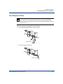
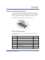
1
296-1011-202
Document Revision 02.01
CVX Multi-Service Access Switch
Release 5.0
August 2001
CVX 600 Multi-Service
Access Switch
Hardware Installation Guide
*Nortel, Nortel Networks, the Nortel Networks corporate logo, the Globemark design, and CVX are trademarks of Nortel
Networks. All other trademarks are the property of their owners.
© 2001 Nortel Networks. All rights reserved. Information in this document is subject to change without notice. Nortel
Networks assumes no responsibility for any errors that may appear in this document.
Printed in the USA
Regulatory and Safety
Regulatory Information
U.S.A. Requirements
FCC Radio Frequency Notice for the CVX 600 Access Switch
This device complies with Part 15 of the FCC Rules. Operation is subject to the following two conditions:
•
This device may not cause harmful interference.
•
This device must accept any interference received, including interference that may cause undesired
operation.
Note: This equipment has been tested and found to comply with the limits for a Class A digital device, pursuant to
Part 15 of the FCC Rules. These limits are designed to provide reasonable protection against harmful interference in a
residential installation. This equipment generates, uses and can radiate radio frequency energy and, if not installed and
used in accordance with the instructions, may cause harmful interference to radio communications. However, there is
no guarantee that interference will not occur in a particular installation. If this equipment does cause harmful
interference to radio or television reception, which can be determined by turning the equipment off and on, the user is
encouraged to try to correct the interference by one or more of the following measures:
•
Reorient or relocate the receiving antenna.
•
Increase the separation between the equipment and receiver.
•
Connect the equipment into an outlet on a circuit different from that to which the receiver is connected.
•
Consult the dealer or an experienced radio/TV technician for help.
FCC Part 68 General Information
This equipment complies with Part 68 of the FCC rules. This equipment uses the following USOC RJ-48 jacks:
Interface
Service Code
Facility Code
1.544 Mb/s superframe format (SF) without 6.0N
line power
04DU9-BN
1.544 Mb/s superframe format (SF) and
B8ZS without line power
6.0N
04DU9-DN
1.544 Mb/s ANSI extended superframe
format (ESF) without line power
6.0N
04DU9-1KN
1.544 Mb/s ANSI extended superframe
format (ESF) and B8ZS without line power
6.0N
04DU9-1SN
296-1011-202 Rel. 5.0, Doc. Rev. 02.01
iii
CVX 600 Hardware Installation Guide
Regulatory Information
If you experience trouble with this equipment, please contact Nortel Networks for repair and warranty information. If
there is a problem with the network, the telephone company may request that you remove the equipment from the
network until the problem is resolved.
Nortel Networks recommends that you install an AC surge protector in the AC outlet to which the equipment is
connected. This helps to prevent damage to the equipment caused by local lightning strikes or other electrical surges.
FCC and Telephone Company Procedures and Requirements
In order to connect this equipment to the network, you must provide the local telephone company with the registration
number of this equipment, and you must order the proper connections.
To order the proper service, provide the telephone company with the following information:
• Number of required jacks and their USOC numbers
• Sequence in which the trunks are to be connected
• Facility interface codes, by position
UL Listing and CSA Certification - U.S. and Canada
This equipment has been Listed by Underwriter Laboratories, Inc. and certified by CSA for use in the U.S. and
Canada to the requirements of UL 1950. Third Edition - Safety of Information Technology Equipment. Including
Electrical Business equipment and Canadian Standards Association CAN/CSA C22.2 No. 950-95 Third Edition.
Australian Requirements
N441
The regulator for telecommunications and radio communications in Australia is the ACA (Australian
Communications Authority). This equipment is labeled with the A-Tick mark, which indicates that the product
complies with both EMC and Telecommunications requirements and establishes a traceable link between the
equipment and the manufacturer. It is also an indication to the user that the product can be connected to a
telecommunications network.
Canadian Requirements
Canadian Department of Communications Radio Interference Regulations
This digital apparatus (CVX 600) does not exceed the Class A limits for radio-noise emissions from digital apparatus,
as documented in the Radio Interference Regulations of the Canadian Department of Communications.
Règlement sur le brouillage radioélectrique du ministère des Communications
Cet appareil numérique (CVX 600) respecte les limites de bruits radioélectriques visant les appareils numériques de
classe A prescrites dans le Règlement sur le brouillage radioélectrique du ministère des Communications du Canada.
Canada CS-03 Rules and Regulations
Note: The Canadian Department of Communications label identifies certified equipment. The certification means that
the equipment meets certain telecommunications network protective, operational, and safety requirements. The
Department does not guarantee the equipment will operate to the user’s satisfaction.
iv
296-1011-202 Rel. 5.0, Doc. Rev. 02.01
Regulatory and Safety
Regulatory Information
Before installing this equipment, ensure that it is permissible to connect to the facilities of the local
telecommunications company. You must install this equipment using an acceptable connection method.
Repairs to certified equipment should be made by a supplier-designated representative. If you make repairs or
alterations to this equipment, or if the equipment malfunctions, the telecommunications company may request that
you disconnect the equipment.
You should ensure, for your own protection, that the electrical ground connections for the power utility, telephone
lines, and internal water-pipe system, if present, are connected. This precaution may be particularly important in rural
areas.
Caution: You should not attempt to make such connections. You should contact the appropriate inspection authority
or electrician.
Canada CS-03 Règles et règlements
Note: L’étiquette du ministère des Communications du Canada indique que l’appareillage est certifié, c’est-à-dire
qu’il respecte certaines exigences de sécurité et de fonctionnement visant les réseaux de télécommunications. Le
ministère ne garantit pas que l’appareillage fonctionnera à la satisfaction de l’utilisateur.
Avant d’installer l’appareillage, s’assurer qu’il peut être branché aux installations du service de télécommunications
local. L’appareillage doit aussi être raccordé selon des méthodes acceptées.
Les réparations de l’appareillage certifié devraient être confiées à un service désigné par le fournisseur. En cas de
réparation ou de modification effectuées par l’utilisateur ou de mauvais fonctionnement de l’appareillage, le service
de télécommunications peut demander le débranchement de l’appareillage.
Pour leur propre sécurité, les utilisateurs devraient s’assurer que les mises à la terre des lignes de distribution
d’électricité, des lignes téléphoniques et de la tuyauterie métallique interne sont raccordées ensemble. Cette mesure de
sécurité est particulièrement importante en milieu rural.
Attention: Les utilisateurs ne doivent pas procéder à ces raccordements, mais doivent plutôt faire appel aux pouvoirs
de réglementation en cause ou à un électricien, selon le cas.
European Requirements
EMI/EN 55 022 Statement
This certifies that the Nortel Networks CVX 600 switch is shielded against the generation of radio interference in
accordance with the application of Council Directive 89/336/EEC. Conformity is declared by the application of EN 55
022:1998 and EN 55 024:1998.
Warning: This is a Class A product. In a residential area, this product may cause radio interference, in which case the
user may be required to take the appropriate measures.
EC Declaration of Conformity
This product conforms to the provisions of Council Directive’s EMC Directive (89/336/EEC), Low Voltage Directive
(73/23/EEC), and R+TTE Directive (1999/5/EC).
296-1011-202 Rel. 5.0, Doc. Rev. 02.01
v
CVX 600 Hardware Installation Guide
Regulatory Information
Japan/Nippon Requirements Only
Voluntary Control Council for Interference (VCCI) Statement
Voluntary Control Council for Interference (VCCI) Statement
This equipment is in the 1st category (information equipment to be used in commercial and/or industrial areas) and
conforms to the standards set by the Voluntary Control Council for Interference by Data Processing Equipment and
Electronic Office Machines that are aimed at preventing radio interference in commercial and/or industrial areas.
Consequently, when this equipment is used in a residential area or in an adjacent area thereto, radio interference may
be caused to equipment such as radios and TV receivers.
JATE Requirements
This certifies that the Nortel Networks CVX 600 conforms to the standards set by JATE (Japan Approvals Institute for
Telecommunications Equipment) as of 06/06/01 with Approval Numbers CD01-0459JP and L01-0145.
vi
296-1011-202 Rel. 5.0, Doc. Rev. 02.01
Regulatory and Safety
Safety Warnings
Safety Warnings
General Warnings
The following safety warnings apply:
• Mechanical hazards and electrical shock hazards are possible if you remove one or more of the modules. There are
no operator-serviceable modules. Only qualified personnel should service this equipment.
• This equipment must be connected to a protective ground according to the instructions in this manual. Improper
grounding may result in electrical shock.
• This equipment does not provide safety isolation between any port that is connected to a digital network
termination point or any port to which terminal equipment is connected.
• The wall circuit breaker provides the main protection for this equipment. For -48 VDC operation, the equipment
must reside on its own circuit with a breaker rated for 20 A.
• Ensure that rack installation does not result in airflow blockage to power supply vents or chassis vents.
• Before installing the CVX 600 switch, ensure that the rack is sturdy and well-secured.
DC Power Supply Warnings
The DC power supply must be installed in a restricted area, such as an equipment closet or room, in compliance with
Articles 110-16, 110-17, and 110-18 of the National Electric Code, ANSI/NFPA 70. The DC power source must be
isolated from the AC power source and must have a proper ground.
The grounded conductor of the DC supply circuit can be connected to the frame grounding conductor of the CVX 600
switch. In this case, the following conditions apply:
• The CVX 600 switch must be connected to the DC power supply grounded conductor or bonding jumper from the
grounding terminal bar or bus to which the DC power supply grounded conductor is connected.
• The CVX 600 switch must be located in the same area as other equipment having a connection between the
grounded conductor of the same DC supply circuit and the grounding conductor, and also the point of grounding of
the DC system. The DC system must not be grounded elsewhere.
• You must not switch or disconnect devices in the grounded conductor between the DC power supply and the point
of connection of the grounding electrode conductor.
• A readily accessible disconnect device may be provided in the fixed wiring for a DC power supply. The device must
be rated for the voltage and current specified.
• Before installing equipment in a rack, consider the overall loading of the branch circuit.
For safety purposes, the DC power supply requires connection to a grounded outlet. To prevent possible injury from
voltages on the telecommunications network, disconnect all telecommunications network lines before disconnecting
the DC power supply from the grounded outlet.
296-1011-202 Rel. 5.0, Doc. Rev. 02.01
vii
CVX 600 Hardware Installation Guide
Safety Warnings
Lithium Battery Caution
Caution: Danger of explosion if battery is incorrectly replaced. Replace only with the same or equivalent type
recommended by the manufacturer. Discard used batteries according to the manufacturer’s instructions.
Attention: Il y a danger d’explosion s’il y a remplacement incorrect de la batterie. Remplacer uniquement avec une
batterie du même type ou d’un type recommandé par le constructeur. Mettre au rebut les batteries usagées
conformément aux instructions du fabricant.
viii
296-1011-202 Rel. 5.0, Doc. Rev. 02.01
Regulatory and Safety
Regulatory Information ......................................................................................................iii
U.S.A. Requirements ..................................................................................................iii
Australian Requirements ............................................................................................ iv
Canadian Requirements ............................................................................................ iv
European Requirements ............................................................................................. v
Japan/Nippon Requirements Only ............................................................................. vi
Safety Warnings ...............................................................................................................vii
General Warnings ......................................................................................................vii
DC Power Supply Warnings .......................................................................................vii
Lithium Battery Caution .............................................................................................viii
Preface
About This Guide.............................................................................................................. xv
Introduction ............................................................................................................... xv
Topics ........................................................................................................................ xv
Chapters and Appendixes in This Guide .........................................................................xvi
Information About CVX Products ....................................................................................xvii
About This Release ..................................................................................................xvii
Accessing Related Documentation ..........................................................................xvii
Accessing Software Upgrades .................................................................................xvii
Customer Services ........................................................................................................ xviii
Technical Support .................................................................................................... xviii
Product Damage ..................................................................................................... xviii
Equipment Problems ............................................................................................... xviii
296-1011-202 Rel. 5.0, Doc. Rev. 02.01
ix
Contents
Contents
Contents
Chapter 1
Chassis Installation
About This Chapter..........................................................................................................1-1
Introduction ..............................................................................................................1-1
Topics .......................................................................................................................1-1
CVX 600 Chassis Overview ...........................................................................................1-2
Description ...............................................................................................................1-2
Remote Access Configuration ..................................................................................1-2
Where to Install ........................................................................................................1-2
Front View of CVX 600 Chassis ...............................................................................1-3
Rear View of CVX 600 Chassis ...............................................................................1-4
Preparing the Site for the Installation ..............................................................................1-5
Overview ..................................................................................................................1-5
Reference .................................................................................................................1-5
Mounting Options .....................................................................................................1-5
Mounting the CVX 600 in a Rack ...................................................................................1-7
Rack Capacity ..........................................................................................................1-7
Rack Requirements ..................................................................................................1-7
Nortel Networks Rack Recommendation .................................................................1-7
Rack Placement .......................................................................................................1-7
Ceiling Requirements ...............................................................................................1-8
Size and Weight Considerations ..............................................................................1-8
Reference .................................................................................................................1-8
Nortel Networks PTE 2000 Rack .............................................................................1-8
Access Considerations ........................................................................................... 1-11
Rack Cooling Requirements .................................................................................. 1-11
AC and DC Power ........................................................................................................1-12
Description .............................................................................................................1-12
Preparing for the CVX 600 Installation .........................................................................1-14
Overview ................................................................................................................1-14
Unpacking the Shipment ........................................................................................1-14
Checking the Shipment ..........................................................................................1-15
Tools and Equipment Needed ................................................................................1-16
x
296-1011-202 Rel. 5.0, Doc. Rev. 02.01
Contents
Installing the CVX 600 Chassis ....................................................................................1-18
Mounting Options ...................................................................................................1-18
Positioning the Chassis on a Flat Surface .............................................................1-18
Installing the Feet on the Bottom of the Chassis ....................................................1-19
Mounting the Chassis in a Rack .............................................................................1-20
Telco and EIA Rack Hole Spacing .........................................................................1-21
Hardware Needed to Complete the Chassis Installation ........................................1-22
Installing the Chassis .............................................................................................1-23
Chapter 2
Chassis Connections
About This Chapter..........................................................................................................2-1
Introduction ..............................................................................................................2-1
Topics .......................................................................................................................2-1
Connecting Alarms .........................................................................................................2-2
Introduction ..............................................................................................................2-2
Alarm Categories .....................................................................................................2-2
Alarm Types .............................................................................................................2-3
Reference .................................................................................................................2-5
Procedure .................................................................................................................2-6
Connecting Network Cables ...........................................................................................2-7
Overview ..................................................................................................................2-7
Reference .................................................................................................................2-7
Connecting to 10/100BASE-T Interfaces .................................................................2-8
Connecting to DS1/T1 Interfaces .............................................................................2-9
Connecting to E1 Interfaces ...................................................................................2-10
Connecting to DS3 Interfaces ................................................................................ 2-11
Connecting to the HSSI Interface ...........................................................................2-12
Connecting to the OC3/STM1 Interface .................................................................2-13
296-1011-202 Rel. 5.0, Doc. Rev. 02.01
xi
Contents
Connecting Power to the Chassis ................................................................................2-16
Before You Start .....................................................................................................2-16
Requirements .........................................................................................................2-16
Grounding the Chassis ..........................................................................................2-17
Connecting to a Customer-Supplied DC Power Source ........................................2-21
Next Step ...............................................................................................................2-24
Connecting Chassis to an AC Power Source .........................................................2-25
Routing the Cables .......................................................................................................2-27
Cable Mounts .........................................................................................................2-27
Suggested Use .......................................................................................................2-27
Locations of Cable Mounts .....................................................................................2-27
Routing Fiber Optic Cables ....................................................................................2-28
Installing and Removing the Flash Memory Cards .......................................................2-29
Description .............................................................................................................2-29
Reference ...............................................................................................................2-29
Inserting a Flash Memory Card ..............................................................................2-30
Removing a Flash Memory Card ...........................................................................2-31
Connecting Equipment to the Console Port .................................................................2-32
Introduction ............................................................................................................2-32
Connecting a Terminal ...........................................................................................2-33
Connecting a PC ....................................................................................................2-35
Connecting a Modem .............................................................................................2-37
Connecting a Terminal Server ................................................................................2-39
Connecting Equipment to a Local Ethernet Port ..........................................................2-41
Description .............................................................................................................2-41
Connecting a Remote Device Using an Ethernet Port ...........................................2-41
Applying Power to the CVX 600 ...................................................................................2-42
Procedure ...............................................................................................................2-42
xii
296-1011-202 Rel. 5.0, Doc. Rev. 02.01
Contents
Checking the LEDs .......................................................................................................2-43
Introduction ............................................................................................................2-43
SCC-SM, SCC-RLTM (Ethernet 10/100 Mb/s ports) ..............................................2-44
SCC-HSSI-SM, SCC-HSSI-RLTM .........................................................................2-46
Optical SCC-II ........................................................................................................2-48
Optical DAC ...........................................................................................................2-51
DAC-SM LEDs .......................................................................................................2-52
MAC-SM LEDs .......................................................................................................2-54
Chapter 3
Replacing CVX 600 Components
About This Chapter..........................................................................................................3-1
Introduction ..............................................................................................................3-1
Topics .......................................................................................................................3-1
Attaching the Antistatic Wrist Strap .................................................................................3-2
Location of Wrist Strap .............................................................................................3-2
Purpose of Wrist Strap .............................................................................................3-2
How to Attach the Wrist Strap ..................................................................................3-2
Replacing Modules and Filler Panels .............................................................................3-4
Introduction ..............................................................................................................3-4
Removing and Installing Filler Panels ......................................................................3-4
Replacing the SCC-SM .......................................................................................... 3-11
Replacing the SCC-LTM/RLTM ..............................................................................3-16
Replacing Other Service Modules ..........................................................................3-21
Replacing the DAC-LTM/-RLTM .............................................................................3-26
Replacing the Fan Module ............................................................................................3-31
Description .............................................................................................................3-31
Removing the Fan Module .....................................................................................3-32
Installing a Fan Module ..........................................................................................3-34
Replacing a PDU Module .............................................................................................3-36
Description .............................................................................................................3-36
Removing the PDU Module ....................................................................................3-36
Installing a PDU Module .........................................................................................3-38
296-1011-202 Rel. 5.0, Doc. Rev. 02.01
xiii
Contents
Replacing a Power Module ...........................................................................................3-40
Description .............................................................................................................3-40
Removing the Power Module .................................................................................3-40
Installing a Power Module ......................................................................................3-42
Ordering Replacement Components ............................................................................3-44
How to Order ..........................................................................................................3-44
Appendix A
Technical Specifications
About This Appendix ...................................................................................................... A-1
Introduction ............................................................................................................. A-1
Topics ...................................................................................................................... A-1
Chassis Specifications and Clearances ........................................................................ A-2
Dimensions, Weight, Slot Capacity ......................................................................... A-2
Clearance ................................................................................................................ A-2
Environmental Specifications ........................................................................................ A-3
Specifications .......................................................................................................... A-3
Cooling Requirements ................................................................................................... A-4
Need for Ventilation ................................................................................................. A-4
Methods of Cooling ................................................................................................. A-4
Airflow ..................................................................................................................... A-4
Electromagnetic Emissions and Radio Frequency ........................................................ A-5
CVX 600 Requirements .......................................................................................... A-5
Cable Specifications ...................................................................................................... A-6
Cables Supplied by Nortel Networks ....................................................................... A-6
Cables Supplied by the Customer ........................................................................... A-6
Management Console Cable Specifications ........................................................... A-7
HSSI Interface ......................................................................................................... A-9
Ethernet 10/100BASE-TX Interface Cable Specifications ......................................A-11
E1 and T1 Interface Line Specifications ................................................................ A-12
E1 and T1 Shielded Cable Specifications ............................................................. A-13
DS3 Coaxial Cable Specifications ......................................................................... A-13
Optical Cable Specifications ................................................................................. A-13
xiv
296-1011-202 Rel. 5.0, Doc. Rev. 02.01
Contents
Tandem CVX to RAS CVX Crossover Cable ............................................................... A-14
Introduction ........................................................................................................... A-14
Tool and Parts Needed .......................................................................................... A-14
Pin Data ................................................................................................................ A-14
Audible and Visual Alarm Interface Specifications ...................................................... A-16
Alarm Interface Connector
.................................................................................. A-16
Signals .................................................................................................................. A-16
Reference .............................................................................................................. A-16
Power Specifications ................................................................................................... A-17
Power Options ....................................................................................................... A-17
AC Power Requirements ....................................................................................... A-17
DC Power Requirements ...................................................................................... A-17
SCC-LTM/-RLTM Interfaces ........................................................................................ A-18
DAC-LTM/-RLTM External Clock Interface ................................................................. A-19
296-1011-202 Rel. 5.0, Doc. Rev. 02.01
xv
Preface
About This Guide
Introduction
This guide describes how to install the Nortel Networks CVX* 600 Multi-Service
Access Switch for Telco and Internet service provider (ISP) customers. Because
installation procedures vary between Telco and ISP customers, use this manual as
a guide for installation.
Topics
This preface covers the following topics:
Topic
Page
Chapters and Appendixes in This Guide
xvi
Information About CVX Products
xvii
About This Release
xvii
Accessing Related Documentation
xvii
Accessing Software Upgrades
xvii
Customer Services
xviii
Technical Support
xviii
Product Damage
xviii
Equipment Problems
xviii
296-1011-202 Rel. 5.0, Doc. Rev. 02.01
xv
CVX 600 Hardware Installation Guide
Chapters and Appendixes in This Guide
Chapters and Appendixes in This Guide
This guide contains the following chapters and appendixes:
xvi
For
Go to
Chassis Installation
Chapter 1
Chassis Connections
Chapter 2
Replacing CVX 600 Components
Chapter 3
Technical Specifications
Appendix A
296-1011-202 Rel. 5.0, Doc. Rev. 02.01
Preface
Information About CVX Products
Information About CVX Products
About This Release
This version of the CVX access switch documentation supports software
delivered to customers using CVX Release 5.0 software.
Accessing Related Documentation
For information about gaining access to documentation, contact your Nortel
Networks account representative.
Accessing Software Upgrades
Software upgrades are accessible online through the World Wide Web at http://
www.nortelnetworks.com. Click Customer Support > Software Distribution
and follow the instructions to download software upgrades for your CVX product.
Access to software upgrades is available to customers with Performance Pack
support agreements. Contact your Nortel Networks account representative for
more information about Performance Packs or gaining access to software
upgrades.
296-1011-202 Rel. 5.0, Doc. Rev. 02.01
xvii
CVX 600 Hardware Installation Guide
Customer Services
Customer Services
Technical Support
In the USA and Canada: If you are within your warranty period or have
purchased a Performance Pack support agreement covering your CVX network,
dial 1-800-758-4827 to contact a Technical Support engineer. If you would like
information regarding Performance Packs, please contact your Nortel Networks
account representative.
Outside the USA: Contact your Regional Nortel Networks Support Prime.
Product Damage
If any part of the CVX 600 is damaged, contact the shipper to conduct an
inspection and prepare a damage report. Save the shipping container and all
packing materials until the inspection and the damage report are completed.
In addition, contact Technical Support as instructed in the previous section so that
arrangements can be made for replacement equipment. Do not return any part of
the shipment until you receive detailed instructions from a technical
representative.
Equipment Problems
If your equipment is not working properly, you should immediately remove it
from the telephone line to prevent any possible damage to the telephone network.
If the telephone company identifies a problem, they may notify you prior to
discontinuing telephone service. After notification, you will be given an
opportunity to correct the problem. You will also be informed of your right to file
a complaint with the Federal Communications Commission (FCC).
If repair or modification is required in order for your equipment to operate
properly, contact Technical Support. All repairs or modifications must be
completed by Nortel Networks or an authorized Nortel Networks representative.
xviii
296-1011-202 Rel. 5.0, Doc. Rev. 02.01
Chapter 1
Chassis Installation
About This Chapter
Introduction
This chapter describes how to install the CVX 600 chassis.
Topics
This chapter covers the following topics:
Topic
Page
CVX 600 Chassis Overview
1-2
Preparing the Site for the Installation
1-5
Mounting the CVX 600 in a Rack
1-7
AC and DC Power
1-12
Preparing for the CVX 600 Installation
1-14
Installing the CVX 600 Chassis
1-18
296-1011-202 Rel. 5.0, Doc. Rev. 02.01
1-1
CVX 600 Hardware Installation Guide
CVX 600 Chassis Overview
CVX 600 Chassis Overview
Description
The CVX 600 chassis has 6 slots: 4 slots are reserved for the modem access cards
(MACs) and digital access cards (DACs), and 2 slots are reserved for the system
control cards (SCCs).
Remote Access Configuration
The CVX 600 chassis configured for remote access is equipped with the
following:
•
An internal fan module for system cooling
•
A redundant DC power interface
•
An optional redundant AC power module
Where to Install
You can install the CVX 600 chassis on a flat surface, or you can install it in a
Telco or standard EIA 19-inch or 23-inch computer rack.
Note: A 23-inch computer rack requires optional mounting hardware,
which you can order from Nortel Networks.
1-2
296-1011-202 Rel. 5.0, Doc. Rev. 02.01
Chassis Installation
CVX 600 Chassis Overview
Front View of CVX 600 Chassis
The following figure shows the front of the CVX 600 chassis.
AC Power
Modules
PDUs (Circuit Breaker Modules)
AC Chassis Option
AC PM
AC PM
AC PM 2
BIP
I
ESD
Jack
I
PDU 2
O
BIP
PDU 1
O
Fans
AC PM 1
ESD Jack
Good
Redun
Fail
Modem/ISDN
Pwr
Good
Fail
Modem/ISDN
Pwr
Good
Redun
Fail
Modem/ISDN
Pwr
1
RESET
PCMCIA
2
12
Two slots
for primary
and redundant
system control
cards (SCCs)
2
1
RESET
PCMCIA
9
3
8
11
10
2
10/100 Enet
1
3
10/100 Enet
1
2
6
5
HSSI
Fail
SCC
PRI
HSSI
Pwr
Good
Redun
Fail
System
Pwr
SCC
SEC
7
3
4
YEL RED
1
2
Fail
DAC DS1x12
Four slots for digital
access cards (DACs)
and modem access
cards (MACs)
System
Good
Pwr
3
4
Good
2
Redun
Fan
Module
Redun
1
Redun
CVX-6oo
DC Chassis Option
BIP
I
ESD
Jack
I
PDU 2
O
BIP
PDU 1
O
Fans
Good
Redun
Fail
Pwr
Good
Redun
1
2
1
2
12
11
RESET
PCMCIA
RESET
PCMCIA
9
3
8
10
2
10/100 Enet
1
3
10/100 Enet
1
2
5
4
6
HSSI
HSSI
Fail
7
3
Modem/ISDN
Fail
Pwr
Good
Redun
Modem/ISDN
Fail
Pwr
Good
Redun
1
2
DAC DS1x12
YEL RED
Pwr
Good
Redun
Fail
System
Pwr
SCC
PRI
System
Good
4
SCC
SEC
Fail
2
3
Pwr
1
Redun
Modem/ISDN
CVX-6oo
CVX-0218B
296-1011-202 Rel. 5.0, Doc. Rev. 02.01
1-3
CVX 600 Hardware Installation Guide
CVX 600 Chassis Overview
Rear View of CVX 600 Chassis
The following figure shows the rear of the CVX 600 chassis.
DC power connections
(behind protective cover)
AC chassis option shown
AC PM 2
AC PM 1
ESD
jack
PDU 2 DC INPUT B
PDU 1 DC INPUT A
DS3
Tx
Rx
1
1
1
E 1 x 12
1
DS1 x 12
Clock
our slots
or line
ermination
odules
Grounding
lugs/screw
2
3
4
5
6
7
8
10
9
10
11
12
11
2
2
Main Chassis
Clock
2
3
4
5
6
7
8
9
12
3
4
4
1
2
System
OC3/STM1
Crit
Ret
Maj
Audible
Ret
Min
Link
Ret
Crit
Ret
Maj
RX
Ret
Link
Min
RX
Ret
Link
10/100 Enet
RX
Console
Visual
Alarms
10/100 Enet
10/100 Enet
5
3
HSSI
System
Controller
only
3
5
6
6
System control card termination module
Grounding
lugs/screw
CVX-0219B
1-4
296-1011-202 Rel. 5.0, Doc. Rev. 02.01
Chassis Installation
Preparing the Site for the Installation
Preparing the Site for the Installation
Overview
Before you install the CVX 600 chassis, you need to prepare your site. Consider
the method of mounting (rack or flat surface), the installation of the rack (if used),
tools and equipment needed, space requirements, and weight. These issues are
addressed in detail in this chapter.
Reference
For information about the environmental requirements and power specifications,
see Appendix A, “Technical Specifications.”
Mounting Options
You can mount the CVX 600 in one of two ways:
•
Position the CVX 600 on a flat, sturdy, horizontal surface. See “Positioning
the Chassis on a Flat Surface” on page 1-18.
•
Mount the CVX 600 in a rack.
296-1011-202 Rel. 5.0, Doc. Rev. 02.01
1-5
1-6
5
6
1
4
5
3
6
1
3
Redun
Failed
AC PM
CVX-6oo
2
1
Redun
Failed
Modem
Good
Power
Redun
Failed
ISDN
Good
Power
Redun
Failed
Filler
1
3
HSSI
Redun
Failed
2
1
2
PCMCIA
2
1
Reset
PCMCIA
1
Ethernet
System
Good
Power
Redun
HSSI
Reset
2
Failed
3
1
Ethernet
Good
1
System
Power
12
11
10
9
8
7
6
5
4
3
2
1
Good
Power
Yellow Red
DS1
Redun
Failed
Modem
Good
Power
Failed
Redun
ISDN
Good
Power
Redun
Failed
Filler
BIP
AC PM 1
BIP
AC PM 1
BIP
BIP
PDU 2
AC PM 2
BIP
PDU 2
AC PM 2
BIP
PDU 2
ESD
ESD
Jack
6
5
HSSI
Redun
Failed
2
2
12
11
10
9
8
7
6
5
4
3
2
1
Good
Power
Yellow Red
DS1
Failed
Redun
Good
Power
Modem
3
Reset
4
1
Redun
Failed
ISDN
Good
Power
Failed
Redun
Filler
1
Ethernet
AC PM 1
BIP
I
O
I
O
PDU 1
PCMCIA
Fans
1
AC PM
3
AC PM 2
1
PDU 2
System
BIP
Good
AC PM 1
AC PM
Power
AC PM 2
Redun
Jack
Failed
ESD
2
BIP
1
3
HSSI
Failed
Redun
2
1
2
PCMCIA
2
1
Reset
PCMCIA
1
Ethernet
System
Good
Power
Redun
HSSI
Reset
2
Failed
3
1
Ethernet
Good
1
System
Power
12
11
10
9
8
7
6
5
4
3
2
1
Good
Power
Yellow Red
DS1
Redun
Failed
Modem
Good
Power
Redun
Failed
Good
Power
ISDN
Modem
Good
Power
Failed
Redun
Good
Redun
ISDN
Power
Failed
Filler
Redun
Failed
Filler
I
O
I
O
PDU 2
2
AC PM 1
I
O
I
O
Redun
Failed
BIP
HSSI
Filler
Yellow Red
BIP
Reset
Redun
Failed
1
2
PCMCIA
2
1
12
11
10
9
8
7
6
5
4
3
2
1
Good
Power
DS1
I
O
I
O
1
3
HSSI
Redun
Failed
2
1
2
PCMCIA
2
1
Reset
PCMCIA
1
Ethernet
System
Good
Power
Redun
HSSI
Reset
2
Failed
3
1
Ethernet
Good
1
System
Power
AC PM 2
1
ISDN
Good
Power
Redun
Failed
2
PCMCIA
HSSI
Reset
AC PM 1
Failed
Redun
Good
12
11
10
9
8
7
6
5
4
3
2
1
Power
Yellow Red
DS1
Modem
Good
Power
Good
ISDN
Power
Redun
2
Failed
1
3
HSSI
Redun
Failed
2
1
2
PCMCIA
2
1
Reset
PCMCIA
1
Ethernet
System
Good
Power
Redun
HSSI
Reset
2
Failed
3
1
Ethernet
Good
1
System
Power
Redun
Failed
Filler
12
11
10
9
8
7
6
5
4
3
2
1
Good
Power
Yellow Red
DS1
Redun
Failed
Good
Power
Modem
I
O
I
O
Redun
Failed
ISDN
Good
Power
Redun
Failed
1
3
Redun
Failed
1
Filler
2
PCMCIA
2
1
I
O
I
O
2
PCMCIA
HSSI
Reset
1
Ethernet
System
Good
Power
Redun
HSSI
Reset
2
Failed
3
1
Ethernet
Good
1
System
Power
12
11
10
9
8
7
6
5
4
3
2
1
Good
Power
Yellow Red
DS1
PDU 2
Ethernet
Redun
Failed
1
3
1
Ethernet
System
Good
Power
Redun
HSSI
Reset
2
Failed
3
1
Ethernet
Good
1
System
Power
BIP
PCMCIA
Modem
Good
Power
I
O
I
O
Redun
Failed
Modem
Good
Power
Redun
Failed
ISDN
Good
Power
Redun
Failed
Filler
AC PM 2
1
Redun
Failed
Filler
BIP
I
O
I
O
1
3
1
1
3
HSSI
Redun
2
1
2
PCMCIA
2
1
Reset
PCMCIA
1
Ethernet
System
Good
Power
2
Redun
Reset
HSSI
Ethernet
Failed
1
System
Good
3
Failed
1
12
11
10
9
8
7
6
5
4
3
2
1
Good
Power
Yellow Red
DS1
2
PCMCIA
2
1
Power
1
Failed
Redun
Good
12
11
10
9
8
7
6
5
4
3
2
1
Power
Redun
Yellow Red
DS1
Failed
2
PCMCIA
HSSI
Ethernet
Reset
1
3
1
Good
Redun
System
Power
Failed
2
Reset
HSSI
Ethernet
System
Good
Power
Modem
Good
Power
Redun
Failed
Redun
Failed
Good
Power
ISDN
Modem
Good
Power
Failed
Redun
Good
Redun
ISDN
Power
Failed
Filler
Redun
Failed
Filler
I
O
I
O
PDU 2
3
Yellow Red
Redun
Failed
BIP
1
1
2
PCMCIA
1
2
PCMCIA
12
11
10
9
8
7
6
5
4
3
2
1
Good
Power
DS1
ISDN
Good
Power
2
System
Redun
Failed
2
Redun
Failed
2
Good
HSSI
Reset
Modem
Good
Power
I
O
I
O
AC PM 2
Power
1
3
1
Ethernet
System
Good
Power
2
Redun
Reset
HSSI
Ethernet
Failed
1
3
1
System
Good
CVX-6oo
Power
Redun
Failed
AC PM 1
I
O
I
O
Yellow Red
BIP
I
O
I
O
AC PM
PCMCIA
Yellow Red
AC PM
2
12
11
10
9
8
7
6
5
4
3
2
1
Good
Power
DS1
1
2
PCMCIA
2
1
12
11
10
9
8
7
6
5
4
3
2
1
Good
Power
DS1
AC PM
1
2
Redun
Failed
2
PCMCIA
HSSI
Reset
AC PM
PCMCIA
Reset
HSSI
Ethernet
1
3
1
Ethernet
System
Good
Power
Redun
2
Reset
HSSI
Ethernet
Failed
1
3
1
System
Good
AC PM
Power
AC PM 1
I
PDU 1
O
Fans
1
I
O
I
O
AC PM
2
Jack
1
PDU 2
3
PCMCIA
5
System
Jack
Good
4
Power
6
Redun
Filler
AC PM
2
BIP
ESD
Failed
CVX-6oo
1
2
2
1
HSSI
Jack
Reset
PDU 2
PDU 1
Ethernet
6
1
1
3
3
1
4
System
2
Good
BIP
PDU 1
Power
CVX-6oo
I
Fans
O
PDU 2
Fans
Filler
Jack
Redun
Failed
Redun
Failed
5
PCMCIA
ISDN
Good
Redun
ISDN
Power
Failed
Good
Redun
Modem
Power
Failed
4
Good
Yellow Red
6
Power
1
2
PCMCIA
1
2
PCMCIA
12
11
10
9
8
7
6
5
4
3
2
1
Good
Power
DS1
2
Redun
Failed
BIP
3
Modem
Redun
Failed
2
Jack
Good
PDU 2
ESD
Power
HSSI
Reset
CVX-6oo
Redun
Failed
1
3
1
Ethernet
System
Good
Power
Redun
HSSI
Reset
2
Failed
3
1
Ethernet
Good
1
System
Power
1
Yellow Red
BIP
PDU 1
4
I
O
I
O
Fans
3
Filler
PDU 2
2
Redun
Failed
BIP
1
ISDN
Good
Power
CVX-6oo
7
Redun
3
5
Failed
Good
5
6
Modem
Power
4
9
7
6
8
Redun
4
3
2
5
6
9
8
12
11
10
PDU 2
11
1
2
PCMCIA
2
1
5
PCMCIA
Failed
Good
1
Power
Yellow Red
DS1
1
12
Redun
Failed
2
BIP
PDU 1
10
HSSI
Reset
Fans
Good
1
3
1
Ethernet
System
Good
Power
Redun
HSSI
Reset
2
Failed
3
1
Ethernet
Good
1
System
Power
PDU 2
Power
I
O
I
O
BIP
DS1
Filler
CVX-6oo
Redun
Failed
Redun
Failed
2
2
BIP
3
HSSI
ISDN
Good
Power
5
Reset
Redun
4
Ethernet
Failed
Good
Modem
Power
6
1
2
1
3
Redun
Failed
CVX-6oo
PDU 1
1
2
Yellow Red
Fans
System
BIP
PDU 2
Good
1
PCMCIA
12
11
10
9
8
7
6
5
4
3
2
1
Good
Power
DS1
BIP
Power
2
2
Redun
Reset
HSSI
Failed
1
3
1
Good
Ethernet
System
Power
6
Redun
1
PCMCIA
2
Redun
Reset
HSSI
Ethernet
Failed
1
3
1
Good
System
Power
BIP
I
O
I
O
BIP
PDU 2
Failed
Filler
3
2
Redun
BIP
5
HSSI
Failed
Good
ISDN
Power
BIP
4
Reset
Redun
1
Ethernet
Failed
Good
Modem
Power
BIP
PDU 1
1
Redun
Failed
BIP
Fans
3
Yellow Red
CVX-6oo
1
1
2
PCMCIA
1
2
PCMCIA
12
11
10
9
8
7
6
5
4
3
2
1
Good
Power
DS1
BIP
PDU 2
System
Redun
Failed
2
BIP
I
O
HSSI
Reset
BIP
Good
2
1
3
1
Ethernet
System
Good
Power
2
Redun
Reset
HSSI
Ethernet
Failed
1
3
1
BIP
Power
1
PCMCIA
3
2
4
1
1
PCMCIA
PDU 1
System
3
Good
5
Power
4
I
O
6
Filler
1
Redun
Fans
PDU 1
Failed
ISDN
3
Good
5
Power
4
Redun
6
Failed
1
Modem
6
Good
Fans
PDU 1
Power
5
Redun
1
Failed
3
Yellow Red
4
4
5
3
6
2
Fans
PDU 1
7
4
5
1
1
3
6
Fans
PDU 1
9
3
8
5
11
4
12
6
10
1
Good
5
Power
4
DS1
6
Redun
Fans
PDU 1
Failed
3
2
1
HSSI
Fans
PDU 1
Reset
5
Ethernet
4
1
6
3
1
1
3
System
5
Good
4
Power
6
Redun
Fans
PDU 1
Failed
3
2
1
HSSI
Fans
PDU 1
Reset
5
Ethernet
4
1
6
3
1
1
3
System
Fans
PDU 1
Good
Fans
Power
CVX 600 Hardware Installation Guide
Preparing the Site for the Installation
ESD
AC PM
Jack
CVX-6oo
ESD
Jack
7 ft Telco rack
2
CVX-6oo
ESD
Jack
AC PM
ESD
Jack
2
CVX-6oo
ESD
Jack
AC PM
ESD
Jack
CVX-6oo
ESD
2
Jack
2
Surface mounted
2
CVX-6oo
ESD
Jack
AC PM 2
AC PM
BIP
PDU 2
ESD
2
Jack
CVX-6oo
2
CVX-6oo
ESD
2
AC PM
2
CVX-6oo
ESD
Jack
AC PM
ESD
2
CVX-6oo
ESD
Jack
CVX-0220A
296-1011-202 Rel. 5.0, Doc. Rev. 02.01
Chassis Installation
Mounting the CVX 600 in a Rack
Mounting the CVX 600 in a Rack
Rack Capacity
You can install up to seven AC-powered CVX 600s or up to ten DC-powered
CVX 600s in a standard Telco or Electronic Industries Association (EIA) rack.
Rack Requirements
The rack must meet the following requirements:
•
Heavy-duty steel construction
•
EIA standard hole spacing, or a Telco rack with 25 mm spacing
•
Width of 19 in. (48.26 cm) or 23 in. (58.42 cm), depth of 24 in. (60.96 cm)
Nortel Networks Rack Recommendation
Nortel Networks recommends using a Physical Telecommunications Environment
(PTE) 2000 rack.
Caution: Nortel Networks does not authorize the use of racks with front
or rear doors or side panels. The operating environment must provide
airflow at 200 cubic feet per minute (CFM) per CVX 600 chassis at a
temperature range of 32° to 104°F (0° to 40°C). The optimal ambient
temperature for reliable CVX 600 operation is 68° to 77°F (20° to 25°C).
Rack Placement
The rack you plan to install should be in an area that is:
•
A dedicated equipment room or closet, wired in accordance with local
electrical codes
•
Large enough to allow easy access for service and maintenance
•
Free of dust, smoke, and electrostatic discharge
296-1011-202 Rel. 5.0, Doc. Rev. 02.01
1-7
CVX 600 Hardware Installation Guide
Mounting the CVX 600 in a Rack
•
Properly ventilated
•
Well lighted
Note: The recommended aisle spacing is 29.5 in. (750 mm).
Ceiling Requirements
Consider the following ceiling requirements before you install the rack:
•
The ceiling should be clear of obstructions such as beams, heating and air
conditioning ducts, water pipes, and lights.
•
The ceiling should not have sprinklers; however, appropriate fire protection
devices should be available.
Size and Weight Considerations
Before you install the rack at your site, make sure that the equipment room can
accommodate the size and weight of the rack and the CVX 600.
To determine the total weight, add the weight of all of the CVX 600 chassis (about
70 lb, 31.7 kg each for the AC chassis option, NTDZ10BA), and the weight of the
rack.
Reference
For information about general equipment requirements, see the Telcordia Network
Equipment Building Standards (NEBS), General Equipment Requirements
(GR-63).
Nortel Networks PTE 2000 Rack
Nortel Networks offers two types of PTE 2000 racks:
1-8
•
PTE 2000 NEBS-compliant rack (NTRU0134)
•
PTE 2000 ETSI-compliant rack (NTRU0234)
296-1011-202 Rel. 5.0, Doc. Rev. 02.01
Chassis Installation
Mounting the CVX 600 in a Rack
Reference
For PTE 2000 rack installation instructions, see the PTE 2000 Installation Guide
(IM 07-08-1543).
Anchor Kits
Nortel Networks offers four types of PTE 2000 anchor kits; each kit contains two
anchors. If you do not plan to order anchor kits from Nortel Networks, you can
use other anchor kits that provide the same level of seismic protection.
Note: You must use six floor anchors to secure the PTE 2000 rack to the
equipment-room floor.
The following table describes each of the anchor kits.
Kit Number
Earthquake Zone
Compliance
Floor Type
Notes
NTRU0324
Up to and including zone 4 Raised or concrete
floor
Includes M12
anchoring hardware
(2 anchors)
NTRU0328
Up to and including zone 4 Concrete floor only
Includes M12
anchoring hardware
(2 anchors)
NTRU0323
Up to and including zone 2 Raised or concrete
floor
Includes 3/8 in.
anchoring hardware
(2 anchors)
NTRU0326
Up to and including zone 2 Concrete floor only
Includes 3/8 in.
anchoring hardware
(2 anchors)
296-1011-202 Rel. 5.0, Doc. Rev. 02.01
1-9
CVX 600 Hardware Installation Guide
Mounting the CVX 600 in a Rack
Space Requirements
The following table lists the PTE 2000 racks and dimensions.
Rack Type
Part Number
Width in
Inches (mm)
Depth in
Inches (mm
Height in
Inches (mm)
NEBS-compliant rack
NTRU0134
23.6 (600)
23.6 (600)
83.66 (2125)
ETSI-compliant rack
NTRU0234
23.6 (600)
23.6 (600)
86.6 (2200)
Flooring Requirements
You must anchor the PTE 2000 rack to the equipment-room floor. The flooring
can be one of the following types:
•
Raised floor tiles, ideally with a clearance of 18 in. (45.5 cm), and a subfloor
cable management system
•
Bare concrete floor
Depth for Drilling
If you plan to install the PTE 2000 floor anchors on a bare concrete floor, you
must drill to the following depths:
•
2 in. (51 mm) for the 3/8 in. anchor (for zone 2 earthquake compliance,
NTRU0323/NTRU0326)
•
4 in. (103 mm) for the M12 anchor (for zone 4 earthquake compliance,
NTRU0324/NTRU0328)
Warning: Before you begin to drill, make sure you are familiar with the
building construction. If you plan to drill holes in a below-ground
structure, make sure that you do not drill through the concrete into the
vapor barrier. If you do, groundwater may seep through the anchor hole.
1-10
296-1011-202 Rel. 5.0, Doc. Rev. 02.01
Chassis Installation
Mounting the CVX 600 in a Rack
Access Considerations
The doorways, corridors, and elevators leading to the installation site must be able
to accommodate the rack. Consider the following when planning the arrival and
unloading of the PTE 2000 rack:
•
Including the pallet on which the PTE 2000 rack is shipped, the height of the
rack is 91.66 in. (2,325 mm). The pallet width is 39.4 in. (1,000 mm).
•
The weight of an empty PTE 2000 rack is approximately 125 lb (57 kg),
excluding the shipping crate.
•
Use freight elevators (if available) to move the equipment to upper floors.
Rack Cooling Requirements
You can install up to seven AC-powered CVX 600s or up to ten DC-powered
CVX 600s in a standard Telco or EIA rack without front or rear doors or side
panels. Nortel Networks recommends using a PTE 2000 rack.
To ensure proper cooling for the CVX 600, the rack must meet the following
requirements:
•
The operating environment must provide airflow at 200 CFM per CVX 600
chassis at a temperature range of 32° to 104°F (0° to 40°C).
•
The optimal ambient temperature for reliable long-term CVX 600 operation is
68° to 77°F (20° to 25°C).
296-1011-202 Rel. 5.0, Doc. Rev. 02.01
1-11
CVX 600 Hardware Installation Guide
AC and DC Power
AC and DC Power
Description
The CVX 600 uses either an AC or DC power source.
AC Power Option
If you are using AC power from an outlet, you should be installing the AC chassis
option. The AC chassis option contains two independent power modules. If one
module fails, the other module powers the CVX 600.
AC Chassis Option
AC PM
AC PM
AC PM 2
BIP
I
ESD
Jack
I
PDU 2
O
BIP
PDU 1
O
Fans
AC PM 1
Filler
CVX-6oo
Good
Redun
Fail
Pwr
Good
Redun
12
2
1
PCMCIA
RESET
RESET
2
1
PCMCIA
9
3
3
8
11
10
2
2
4
5
6
10/100 Enet
1
7
HSSI
10/100 Enet
1
Fail
HSSI
Modem/ISDN
Fail
Pwr
Good
Redun
YEL RED
1
2
3
DAC DS1x12
Fail
Pwr
Good
Redun
System
Fail
SCC
6
Pwr
SCC
5
System
Good
4
Pwr
2
3
Redun
Modem/ISDN
1
CVX-0237B
1-12
296-1011-202 Rel. 5.0, Doc. Rev. 02.01
Chassis Installation
AC and DC Power
DC Power Option
If you are using an external AC power supply, you should be installing the DC
chassis option.
The DC chassis option requires an external -48 VDC power source.
DC Chassis Option
BIP
I
ESD
Jack
I
PDU 2
O
BIP
PDU 1
O
Fans
Filler
CVX-6oo
Good
Redun
Fail
Pwr
Modem/ISDN
1
Good
Redun
Fail
Pwr
Good
Redun
12
2
1
PCMCIA
RESET
RESET
2
1
3
3
PCMCIA
9
11
10
2
2
5
6
10/100 Enet
1
10/100 Enet
1
7
HSSI
HSSI
Fail
8
YEL RED
1
4
2
3
DAC DS1x12
Fail
Pwr
Pwr
Good
Redun
Fail
System
Pwr
SCC
6
System
Good
4
SCC
5
Redun
Modem/ISDN
2
3
CVX-0238B
Note: Both versions contain internal circuit breaker modules.
296-1011-202 Rel. 5.0, Doc. Rev. 02.01
1-13
CVX 600 Hardware Installation Guide
Preparing for the CVX 600 Installation
Preparing for the CVX 600 Installation
Overview
To prepare for the installation of the CVX 600 chassis, make sure:
•
•
•
The shipment is complete and undamaged.
You have the proper equipment and tools.
You have network lines available.
Unpacking the Shipment
The CVX 600 is secured to a pallet and covered by a box to protect the contents
during shipment. Move the shipping container to the installation site before
unpacking the CVX 600.
To unpack the CVX 600, follow these steps:
Step
Action
1
Using a screwdriver or other tool, pry down the tabs that secure the box to the
pallet.
CVX-0182B
2
1-14
Lift the box up and off the pallet.
296-1011-202 Rel. 5.0, Doc. Rev. 02.01
Chassis Installation
Preparing for the CVX 600 Installation
Step
Action
3
Remove the box containing the accessory kit and other parts. (The AC chassis
option will have two power cords. The DC chassis option will have none.)
4
Remove the packing material surrounding the chassis.
5
Using a Phillips screwdriver, remove the six screws that secure the chassis to
the pallet brackets.
Turn counterclockwise
to remove screws.
AC PM
AC PM
1
AC PM
2
Phillips screwdriver
Fans
AC PM
1
BIP
I
O
PDU
1
BIP
Filler
CVX
6oo
Failed
O
Power
PDU
Good
ISDN
Redun
2
3
2
I
ESD
1
1
2
2
PCMCIA
PCMCIA
Failed
Modem
Power
Good
Redun
Failed
DS1
Yellow Red
Power
Good
1
2
3
4
5
6
7
8
9
Failed
10
Redun
11
12
2
System
Ethernet
Power
Good
1
3
HSSI
1
Reset
Failed
Redun
2
System
Ethernet
Good
1
Power
3
HSSI
1
6
Reset
5
Redun
Jack
4
Phillips screwdriver
Turn counterclockwise
to remove screws.
CVX-0221A
6
Using a 9/16-inch wrench, remove the four bolts that secure the pallet
brackets to the pallet.
7
Remove the four pallet brackets from the pallet.
8
Carefully remove the chassis from the pallet.
Checking the Shipment
Carefully inspect the shipment for completeness, ensuring the items in the
shipping container match those on the packing list affixed to the shipping
container. In particular:
•
Confirm that the shipment includes any additional cables you have ordered.
•
Check all items for shipping damage.
Note: If you detect or suspect any damage, do not install the CVX 600
chassis. See “Technical Support” on page xviii.
296-1011-202 Rel. 5.0, Doc. Rev. 02.01
1-15
CVX 600 Hardware Installation Guide
Preparing for the CVX 600 Installation
Tools and Equipment Needed
Before you install the CVX 600 chassis, ensure that you have all of the necessary
tools, cables, console equipment, and mounting hardware.
Tools
You must have the following tools:
•
Screwdrivers:
— Phillips #2 screwdriver
— 1/16-inch and 1/4-inch flat-tip screwdrivers
•
Nut drivers (nonmetric sizes) for securing power and ground cabling
•
Volt/ohm meter for power connections
Cables and Cable Ties
The shipment does not include the cables required for the telephone side of your
network. Ensure that the installation site has the proper network cabling.
Cable ties are needed to bundle network and power cables, to provide access to
LTM and RLTM modules.
Service Console
You can connect a local terminal or a PC to the CVX 600 to monitor startup
diagnostics and to perform manual startup and configuration. See Chapter 2,
“Chassis Connections,” for information on installing a service console. See the
following software manuals for information on configuring the CVX 600 access
switch:
1-16
•
CVX Multi-Service Access Switch Startup Guide
•
CVX Multi-Service Access Switch Configuration Guide
296-1011-202 Rel. 5.0, Doc. Rev. 02.01
Chassis Installation
Preparing for the CVX 600 Installation
Note: Before you turn on the CVX 600, you should connect a local
terminal or PC to the CVX 600 console port. This console will display
diagnostic information. If there is a startup problem, in which case, you
need to contact Nortel Networks Technical Support (see “Customer
Services” on page xviii).
Mounting Hardware
To install the CVX 600 chassis in a rack, you need a Phillips #2 screwdriver and a
computer rack that meets the specifications listed in “Rack Requirements” on
page 1-7.
If the rack does not have threaded rail holes, you must use cagenuts and cagenut
screws (not supplied).
296-1011-202 Rel. 5.0, Doc. Rev. 02.01
1-17
CVX 600 Hardware Installation Guide
Installing the CVX 600 Chassis
Installing the CVX 600 Chassis
Mounting Options
You can mount the CVX 600 in one of two ways:
•
Position the chassis on a flat, sturdy, horizontal surface.
•
Mount the chassis in a rack.
Positioning the Chassis on a Flat Surface
When positioning the chassis on a flat, sturdy surface, you must ensure that the
surface is:
1-18
•
Large enough for the chassis to operate properly
•
Strong enough to support the combined weight of the chassis and the cables
296-1011-202 Rel. 5.0, Doc. Rev. 02.01
Chassis Installation
Installing the CVX 600 Chassis
Installing the Feet on the Bottom of the Chassis
To install the feet, follow these steps:
Action
1
Carefully lay the chassis on one side.
2
Using a Phillips screwdriver, attach the feet to the four holes in the bottom of
the chassis, near the corners.
PDU 2
AC PM
ESD
Jack
Step
I
I
O
AC PM
CVX-6oo
AC PM 1
BIP
AC PM 2
O
2
1
CIA
PCM
2
1
CIA
PCM
I
12
I
11
O
10
Reset
O
9
8
Reset
7
6
5
1
I
HSS
4
Redun
1
3
I
HSS
Good
1
Good
Power
Redun
Good
Redun
Good
rnet
Ethe
Good
rnet
Ethe
Red
Failed
Power
Redun
System
Failed
Redun
Failed
Power
Fille
ISDN
Yellow
2
1
2
Failed
r
2
1
3
3
Power
Failed
em
Mod
DS1
Power
6
5
4
Fans
3
2
1
PDU 1
BIP
System
CVX-0239A
296-1011-202 Rel. 5.0, Doc. Rev. 02.01
1-19
CVX 600 Hardware Installation Guide
Installing the CVX 600 Chassis
Mounting the Chassis in a Rack
The mounting flanges are preinstalled on the chassis.
Caution: Nortel Networks recommends using a PTE 2000 rack. Nortel
Networks does not authorize the use of racks with front or rear doors or
side panels. The operating environment must provide airflow at 200 cubic
feet per minute (CFM) per CVX 600 chassis at a temperature range of 32°
to 104°F (0° to 40°C). The optimal ambient temperature for reliable
CVX 600 operation is 68° to 77°F (20° to 25°C).
Caution: Before you install the CVX 600 chassis in a rack, ensure that
the rack is sturdy and well secured. A fully configured CVX 600 chassis
weighs about 70 lb, which could make an unsecured rack top-heavy or
unstable.
1-20
296-1011-202 Rel. 5.0, Doc. Rev. 02.01
Chassis Installation
Installing the CVX 600 Chassis
Telco and EIA Rack Hole Spacing
You can use mounting flanges to install the CVX 600 chassis in a Telco or EIA
rack. Telco and EIA racks have 0.5-inch spacing between the dual mounting
holes, and 0.625-inch spacing between the dual mounting hole pairs.
The following figure shows the positions on the mounting flange that you use for
Telco and EIA racks.
AC chassis option
DC chassis option
1
1
2
2
3
3
4
4
5
5
6
EIA: Use positions 2 and 4
TELCO: Use positions 1, 3, 5
7
EIA: Use positions 1, 3, 5, 7
TELCO: Use positions 2, 4, 6
CVX-0222A
Note: Before you install the CVX 600 chassis in a rack, determine the
type of rack you have so that you can properly align the mounting holes.
296-1011-202 Rel. 5.0, Doc. Rev. 02.01
1-21
CVX 600 Hardware Installation Guide
Installing the CVX 600 Chassis
Hardware Needed to Complete the Chassis Installation
To complete the chassis installation, you need the following hardware:
•
Four (for DC chassis option) or eight (for AC chassis option) truss-head
mounting screws (included in the shipment)
•
Phillips #2 screwdriver
Caution: A fully configured CVX 600 chassis can weigh about 70 lb.
You should have someone assist you in lifting and holding the chassis in
position at installation time.
1-22
296-1011-202 Rel. 5.0, Doc. Rev. 02.01
Chassis Installation
Installing the CVX 600 Chassis
Installing the Chassis
To install the chassis, follow these steps:
Step
Action
1
Have someone help you lift the chassis to the desired installation height.
2
Move the chassis up or down to properly align the positions on the mounting
flanges with the mounting holes on the rack.
AC PM
AC PM
1
AC PM
2
Fans
AC PM
1
BIP
I
O
PDU
1
BIP
Filler
CVX
6oo
Failed
O
Power
PDU
7
2
2
PCMCIA
1
PCMCIA
1
8
9
10
12
11
1
Reset
1
Reset
Failed
Modem
Power
Good
Redun
Failed
DS1
ESD
Jack
Yellow Red
Good
1
2
3
Power
2
4
Redun
2
System
Ethernet
Power
Good
1
3
HSSI
Failed
Redun
2
System
Ethernet
Good
1
Power
3
HSSI
Failed
5
5
6
6
4
Redun
I
3
Good
ISDN
Redun
2
CVX-0240A
(continued)
296-1011-202 Rel. 5.0, Doc. Rev. 02.01
1-23
CVX 600 Hardware Installation Guide
Installing the CVX 600 Chassis
Step
Action
3
Insert truss-head screws through each flange hole and into the corresponding
holes on the front vertical supports of the rack.
AC PM
AC PM
1
AC PM
2
Fans
AC PM
1
BIP
I
O
PDU
1
BIP
Filler
CVX
6oo
Failed
O
Power
PDU
12
6
7
8
9
10
11
2
HSSI
2
PCMCIA
1
PCMCIA
1
HSSI
1
Reset
1
Reset
Failed
Modem
Power
Good
Redun
Failed
DS1
ESD
Jack
Yellow Red
Power
Good
1
2
3
Redun
2
System
Ethernet
Good
Power
Failed
System
Ethernet
Power
2
1
3
Good
Redun
3
1
Failed
5
5
6
2
4
4
Redun
I
3
Good
ISDN
Redun
2
Turn clockwise to
tighten screws
(75 in-lb for a
PTE 2000 rack).
CVX-0241A
4
Use a Phillips screwdriver to tighten the screws.
Caution: You must tighten the screws sufficiently to support the CVX
600 chassis. If using the PTE 2000 rack, tighten the provided hex-head
screws to 75 in-lb, using a torque-regulating ratchet. Nortel Networks
cannot recommend a specific torque value for other racks.
1-24
296-1011-202 Rel. 5.0, Doc. Rev. 02.01
Chapter 2
Chassis Connections
About This Chapter
Introduction
This chapter describes how to connect network cabling and optional console
equipment to the CVX 600.
Topics
This chapter covers the following topics:
Topic
Page
Connecting Alarms
2-2
Connecting Network Cables
2-7
Connecting Power to the Chassis
2-16
Routing the Cables
2-27
Installing and Removing the Flash Memory Cards
2-29
Connecting Equipment to the Console Port
2-32
Connecting Equipment to a Local Ethernet Port
2-41
Applying Power to the CVX 600
2-42
Checking the LEDs
2-43
296-1011-202 Rel. 5.0, Doc. Rev. 02.01
2-1
CVX 600 Hardware Installation Guide
Connecting Alarms
Connecting Alarms
Introduction
The SCC-LTM and SCC-RLTM contain a terminal block that allows you to
connect up to three audible alarms and three visual alarms. These alarms alert you
to critical, major, and minor conditions. The left six screw terminals on the
terminal block are available for visual alarms, such as lights; the right six screw
terminals are available for audible alarms, such as bells.
Warning: The contacts on the terminal block are rated at 30 VAC and
have a maximum current rating of 1 ampere (A). The circuit connecting
the alarms must meet the requirements for safety extra-low voltage
(SELV). The wires connecting the alarms must be the appropriate gauge
for alarm devices.
During normal, uninterrupted operation, the contacts remain open. If a failure
occurs, the contacts close and trigger the connected alarm.
Alarm Categories
The following table lists the three general categories of alarms and the possible
causes:
2-2
Alarm
Possible Cause
Critical (Crit)
Hardware failures: the system power supply and fan module have
failed, for example.
Major (Maj)
Communication failures: the link or network connection has failed.
Minor (Min)
Modem failures: the configured thresholds have been exceeded.
296-1011-202 Rel. 5.0, Doc. Rev. 02.01
Chassis Connections
Connecting Alarms
Alarm Types
The following table lists specific alarm types, severity, and possible causes:
Alarm Type
Severity
Description
T1 Alarm
Critical
An alarm condition has been detected on the
specified T1 line, or the signal on the T1 line has
been lost.
T3 Alarm
Critical
An alarm condition has been detected on the
specified T3 line, or the signal on the T3 line has
been lost.
HSSI Port Down Critical
The HSSI port has failed to initialize.
Ethernet Port
Down
Major
The Ethernet port has failed to initialize.
Fan Down
Major
The cooling fans have stopped.
Power Down
Major
The external power source has dropped.
SCC Failover
Major
The primary SCC has failed, and the secondary SCC
has resumed operation. CVXView generates this
alarm. Although the raising trap is generated on the
CVX 600, it does not recognize this as an alarm
condition. This alarm must be cleared manually on
CVXView (Clear Alarms button).
Link Down
Minor
The sending protocol entity recognizes a failure in
one of the communication links represented in the
agent’s configuration.
Slot Down
Minor
Communication has been lost between the indicated
slot and the SCC.
Sonet/SDH
Loss of Signal
Major
Transitions are not detected on incoming signals,
therefore, a loss of signal is declared.
Sonet/SDH
Loss of Frame
Major
An OOF/SEF defect has persisted for a period of 3
milliseconds, therefore, a loss of frame is declared.
Sonet/SDH C2
Mismatch
Minor
The C2 field value in the received frame does not
match the configured value in the SigLabelExpect
attribute.
Sonet/SDH S1
New Event
Minor
The specified STM-1 is in S1 New Alarm. The S1
field in the received frame contains a new value.
(continued)
296-1011-202 Rel. 5.0, Doc. Rev. 02.01
2-3
CVX 600 Hardware Installation Guide
Connecting Alarms
Alarm Type
2-4
Severity
Description
Sonet/SDH S
Minor
Trace Mismatch
The Section Trace string in the received frame does
not match the configured value in the
StraceStringExpect attribute.
Sonet/SDH P
Minor
Trace Mismatch
The Path Trace string in the received frame does not
match the configured value in the
PtraceStringExpect attribute.
Sonet/SDH LOS Major
Alarm Clear
The LOS alarm condition is cleared.
Sonet/SDH LOF Major
Alarm Clear
The LOF alarm condition is cleared.
APS Live
Minor
The designated optical interface is up and can
received calls.
APS Standby
Minor
The designated optical interface is up, but is in
standby mode.
APS Down
Minor
The designated optical interface is down.
ATM Red Alarm Major
The specified link port has a critical alarm, such as
the absence of a line signal.
ATM Yellow
Alarm
Major
The specified link port has an informational alarm.
ATM Alarm
Clear
Major
The specified link port alarms are cleared.
ATM Marker
Port Up
Minor
The STIC Marker port is up.
ATM Marker
Port Down
Minor
The STIC Marker port is down.
ATM Interface
Up
Minor
The ATM interface is up.
ATM Interface
Down
Minor
The ATM interface is down.
ATM Logical
Interface Up
Minor
The logical interface on the ATM interface is up.
ATM Logical
Interface
Minor
The logical interface on the ATM interface is down.
ATM ILMI
Enabled
Minor
The ILMI interface is up.
ATM ILMI
Disabled
Minor
The ILMI interface is down.
296-1011-202 Rel. 5.0, Doc. Rev. 02.01
Chassis Connections
Connecting Alarms
Alarm Type
Severity
Description
ATM PVPC
PVCC Up
Minor
The PVPC/PVCC has been successfully created.
ATM PVPC
PVCC
Minor
The PVPC/PVCC is down.
ATM APS
Switchover
Minor
A link failure caused the PHY driver to turn on the
redundant PHY.
Sonet/SDH
Alarm Sdber
Major
The specified STM-1 is in Signal Degrade Bit Error
Rate alarm. The value set in the
SigDegradeThreshold attribute for this line has
been exceeded.
Sonet/SDH
Alarm Sfber
Major
The specified STM-1 is in Signal Failure Bit Error
Rate alarm. The value set in the
SigFailureThreshold attribute for this line has been
exceeded.
Sonet/SDH
Alarm Sdber
Clear
Major
The specified STM-1 is not in Signal Degrade Bit
Error Rate alarm. The Signal Degrade Bit Error Rate
is now below the SigDegradeThreshold value set in
the configuration.
Sonet/SDH
Alarm Sfber
Clear
Major
The specified STM-1 is not in Signal Failure Bit Error
Rate alarm. The Signal Failure Bit Error Rate is now
below the SigFailureThreshold value set in the
configuration.
Reference
For pinout assignments, see Appendix A, “Technical Specifications.”
296-1011-202 Rel. 5.0, Doc. Rev. 02.01
2-5
CVX 600 Hardware Installation Guide
Connecting Alarms
Procedure
To connect alarms to the terminal block, follow these steps:
Step
Action
1
Select the terminals you want to use for the audible or visual alarm.
2
Use a small flat-tip screwdriver to loosen the two terminal screws for each
alarm device you want to connect. For example, if you want to connect an
audible alarm for a critical condition, loosen the terminal screws for the
terminals labeled Crit(ical) and Ret(urn).
RX
TX
Visual
Alarms
OC3
SCC-RLTM
/STM
Crit
Audible
Ret
Maj
Ret
Min
Ret
Crit
Ret
Maj
Ret
Min
Ret
1-1
Con
sole
System
Redundant
Remove 1/2 inch
of wire insulation.
Connect wires
to alarm device.
Tighten screws to
1 to 2 in-lb, using a
1/16-inch flat-tip
screwdriver.
RX
TX
/STM
1-1
Visual
Alarms
OC3
Crit
Audible
Ret
Maj
sole
System
OC3/STM1
2-6
Ret
Connect wires
to alarm device.
Min
Ret
Crit
Ret
Maj
Ret
Min
Ret
Remove 1/2 inch
of insulation.
Optical SCC-II-LTM
Con
Tighten screws to 1 to 2 in-lb
using a 1/16-inch flat-tip
screwdriver.
CVX-0184C
3
Use a wire stripper to remove approximately 1/2 inch of insulation from the
wires.
4
Insert the wires into the terminals and tighten the screws to 1 to 2 in-lb using a
1/16-inch flat-tip screwdriver.
5
Connect the other end of the wires to the alarm device.
296-1011-202 Rel. 5.0, Doc. Rev. 02.01
Chassis Connections
Connecting Network Cables
Connecting Network Cables
Overview
You will need to attach network cables to the following CVX 600 interfaces:
•
10/100BASE-T (on the SCC-LTM and SCC-RLTM)
•
DS1/T1 (RJ-45/48C)
•
E1 (RJ-45/48C)
•
DS3
•
HSSI
•
Optical (OC3/STM1)
Reference
See Appendix A, “Technical Specifications” for descriptions of the CVX 600
cable interfaces.
296-1011-202 Rel. 5.0, Doc. Rev. 02.01
2-7
CVX 600 Hardware Installation Guide
Connecting Network Cables
Connecting to 10/100BASE-T Interfaces
Each 10/100BASE-T interface on the SCC-RLTM supports one full-duplex
connection.
To connect an Ethernet unshielded twisted pair (UTP) cable to a
10/100BASE-T interface, follow these steps:
Step
Action
1
Plug the UTP connectors into the receptacles.
3
2
RX
Link
10/100 Enet
Link
1
RX
10/100 Enet
Link
10/100 Enet
RX
RX
TX
RX
TX
OC3/
Optical SCC-II-LTM
STM
1-2
Visual
Alarms
OC3/
STM
1-1
Audible
Crit
Ret
Maj
Ret
Min
Ret
Crit
Ret
Maj
Ret
Min
Ret
Con
sole
DE CLASSE 1
System
OC3/STM1
5
CLASS 1
LASER PRODUCT
APPAXXX A LASER
4
10/100 Enet
Link
RX
5XEthernet SCC-RLTM
Link
Crit
Audible
Ret
Maj
Ret
Min
Ret
Crit
Ret
Maj
Ret
Min
Ret
Visual
Alarms
10/100 Enet
RX
1
Link
10/100 Enet
RX
2
Link
10/100 Enet
RX
3
Link
10/100 Enet
RX
HSS
I
3
2
RX
3XEthernet SCC-RLTM
Crit
Audible
Ret
Maj
Ret
Min
Ret
Crit
Ret
Maj
Ret
Min
Ret
Link
Visual
Alarms
10/100 Enet
Link
1
RX
10/100 Enet
Link
10/100 Enet
RX
CVX-0199B
2-8
296-1011-202 Rel. 5.0, Doc. Rev. 02.01
Chassis Connections
Connecting Network Cables
Connecting to DS1/T1 Interfaces
The DS1-DAC-LTM provides 12 or 24 channelized T1 ports and one port for
connecting to an external clocking device.
To connect T1 cables to the T1 ports, and to connect the DS1-DAC-LTM to an
external clocking device, follow this step:
Step
Action
1
Plug the connectors into the receptacles.
Clock
12
Connect to the
external clocking
device (optional).
11
10
9
12 DS1 ports
8
7
6
5
4
2
1
DS112
3
24
Clock
20
21
12
24 DS1 ports
8
16
17
9
13
5
E 1 x 24
4
Connect to the
external clocking
device (optional).
1
Connect to the
telephone network.
CVX-0242A
296-1011-202 Rel. 5.0, Doc. Rev. 02.01
2-9
CVX 600 Hardware Installation Guide
Connecting Network Cables
Connecting to E1 Interfaces
The E1-DAC-LTM provides 12 or 24 E1 ports and one port for connecting to an
external clocking device. To connect E1 cables to the E1 ports, and to connect the
E1-DAC-LTM to an external clocking device, follow this step:
Step
Action
1
Plug the connectors into the receptacles.
Clock
12
11
Connect to the
external clocking
device (optional).
10
9
8
12 E1 ports
7
6
5
4
E 112
3
2
1
24
Clock
20
21
12
24 E1 ports
8
16
17
9
5
13
Connect to the
external clocking
device (optional).
E 1 x 24
4
1
Connect to the
telephone network.
CVX-0243A
Note: Using shielded cabling is an electromagnetic interference (EMI)
requirement for CVX 600 E1 network configurations.
Note: For UK installations using 75 ohm E1 coax, a balun is needed to
connect to the 120 ohm impedance of the CVX switch. Nortel does not
recommend a specific balun panel for this application.
2-10
296-1011-202 Rel. 5.0, Doc. Rev. 02.01
Chassis Connections
Connecting Network Cables
Connecting to DS3 Interfaces
To connect to DS3 interfaces, follow this step:
Step
Action
1
Plug the TX and RX coaxial cable connectors into the appropriate
DS3 receptacles on the SCC or DAC.
2xDS3-SCC-RLTM
3
2
Crit
Ret
Audible
Maj
Ret
Min
Ret
Crit
Ret
Maj
Ret
Min
Ret
Link
Visual
Alarms
RX
10/100 Enet
Link
1
RX
10/100 Enet
TX1
Link
10/100 Enet
RX
TX1
RX1
TX2
RX2
2xDS3-DAC-RLTM
DS3
DS3
DS3 Redundant
Clock Ref
R
TX2
TX1
2xDS3-DAC-LTM
Clock Ref
DS3
DS3
Rx
Tx
DS3-DAC-RLTM
DS3
DS3 Redundant
DS3
Clock Ref
Rx
Tx
DS3-DAC-LTM
DS3
Connect to the
external clocking
device (if used).
DS3
296-1011-202 Rel. 5.0, Doc. Rev. 02.01
Clock Ref
Connect to
the telephone
network.
CVX-0200A
2-11
CVX 600 Hardware Installation Guide
Connecting Network Cables
Connecting to the HSSI Interface
The SCC-HSSI-RLTM contains one HSSI 50-pin interface receptacle. To connect
a HSSI cable, follow this step:
Step
Action
1
Plug the cable connector into the HSSI interface receptacle.
HSS
I
3
2
RX
Link
10/100 Enet
Link
1
RX
10/100 Enet
Link
10/100 Enet
RX
Connect the other end of this
cable to the router or network
switching device.
CVX-0201A
2-12
296-1011-202 Rel. 5.0, Doc. Rev. 02.01
Chassis Connections
Connecting Network Cables
Connecting to the OC3/STM1 Interface
The Optical DAC-LTM contains two sets of optical ports (two primary and two
redundant, each with separate Tx and Rx channels), consisting of a total of eight
optical connections. The Optical SCC-II-LTM contains two sets, with separate Tx
and Rx channels, consisting of a total of four optical connections.
Connections may be made to optical cables with SC single or SC duplex
connectors.
Warning: These devices contain Class 1 laser products, and comply
with 21 CFR 1040.10 and 1040.11 EN 60825-1 - Safety of Laser
Products.
Class 1 lasers are considered eye-safe; however, follow these
appropriate safety measures:
• Always make sure that the CVX switch is powered down before
connecting or disconnecting any optical cables.
• Always make sure all ports or unconnected optical cable ends are
covered before powering up the CVX switch.
• Never remove a cover from a port or attached optical cable while the
CVX switch has power.
Caution: For proper operation, observe the following:
• Never touch the end of the fiber in a connector with anything except
an approved cleaner.
• Always clean the end of the fiber in connectors and optical ports
before connecting the cables. Use an approved cleaner, or a soft cloth
with isopropyl alcohol.
• Never use any optical cable that has been damaged, or that has been
coiled tighter than a 35-mm radius curve.
296-1011-202 Rel. 5.0, Doc. Rev. 02.01
2-13
CVX 600 Hardware Installation Guide
Connecting Network Cables
Connecting an Optical Cable
To connect an optical cable, follow these steps:
Step
Action
1
Remove the rubber plugs from each pair of ports.
1
Rx
Link
RX
TX
RX
TX
OC3/
STM
OC3/
Optical SCC-II-LTM
Visual
Alarms
1-2
STM
1-1
le
CLASS 1
LASER PRODUCT
APPAXXX A LASER
System
DE CLASSE 1
OC3/STM1
Crit
Audible
Ret
Maj
Ret
Min
Ret
Crit
Ret
Maj
Ret
Min
Ret
Conso
B
Rx
B
Tx
A
Rx
A
Tx
Optical DAC-LTM
A
Rx
A
Tx
B
Rx
B
Tx
2
CLASS 1
LASER PRODUCT
APPAXXX A LASER
STMx2DE CLASSE 1
1
CVX-0139D
2-14
296-1011-202 Rel. 5.0, Doc. Rev. 02.01
Chassis Connections
Connecting Network Cables
Step
Action
2
Remove the protective covers from each optical connector.
Remove cover.
Remove covers.
CVX-0138B
3
Orient the the optical cable connector so that the tab aligns with the slot
in the port, and push the cable connector into the port.
1
Rx
Link
RX
TX
RX
Optical SCC-II-LTM
TX
Visual
Alarms
OC3
A
Audible
Crit
Ret
Maj
Ret
Min
Ret
Crit
Ret
Maj
Ret
Min
Ret
Cons
ole
System
OC3
CLASS 1
LASER PRODUCT
APPAXXX A LASER
DE CLASSE 1
Connect to
the optical port.
Clock Ref
Tab
B
Rx
B
Tx
Optical DAC-LTM
A
Rx
A
Tx
A
Rx
A
Tx
B
Rx
B
Tx
2
1
CLASS 1
LASER PRODUCT
APPAXXX A LASER
OC3x2DE CLASSE 1
Connect to the
external clocking
device (if used).
Tab
Connect to the
optical port.
CVX-0140D
296-1011-202 Rel. 5.0, Doc. Rev. 02.01
2-15
CVX 600 Hardware Installation Guide
Connecting Power to the Chassis
Connecting Power to the Chassis
Before You Start
Make sure you can power the CVX 600 using one of the following power sources:
•
A customer-supplied DC power source with frame grounding (for the DC
chassis option)
•
A built-in AC power module (for the AC chassis option)
Requirements
Before you connect the CVX 600 to power and ground at the installation site:
•
Refer to your company or site specifications for information on the torque
requirements for securing power and ground cables.
•
Make sure the switches on both circuit breaker modules (PDUs) are off (o).
Circuit breaker (PDU) switches
Fans
1
BIP
I
O
PDU
1
Modem/ISDN
Good
Redun
BIP
Pwr
Good
Redun
O
Pwr
PDU
2
Pwr
Redun
Good
Failed
Redun
Fail
Good
Redun
ESD
Jack
21
22
23
24
YEL RED
11
11
12
12
13
14
15
16
17
18
19
20
3
RESET
2
PCMCIA
3
RESET
2
PCMCIA
1
2
1
66
77
88
HSSI
2
10/100 Enet
1
HSSI
10/100 Enet
1
99
10
10
YEL RED
Yellow
Red
Pwr
Power
Fail
Good
11
22
33
44
Good
Redun
55
DAC DS1x24
System
Pwr
Good
Redun
Pwr
System
5
6
Fail
4
Fail
Modem/ISDN
I
3
Fail
Modem/ISDN
6oo
Fail
CVX
2
CVX-0202B
•
2-16
Read the “Safety Warnings” on page vii.
296-1011-202 Rel. 5.0, Doc. Rev. 02.01
Chassis Connections
Connecting Power to the Chassis
Grounding the Chassis
Note: In addition to the grounding location shown in the following
sections, the AC chassis option also contains an identical grounding
location in the upper right corner of the rear of the chassis. Either location
may be used.
There are two ways to ground the CVX 600 chassis:
•
Use the NEBS-compliant dual-connector posts.
Console
System Redundant
4
5
6
OR
Ground cables
CVX-0244A
•
Use the compression terminal.
Console
System Redundant
4
5
6
To facility ground
CVX_0245A
296-1011-202 Rel. 5.0, Doc. Rev. 02.01
2-17
CVX 600 Hardware Installation Guide
Connecting Power to the Chassis
Using the NEBS-Compliant Dual-Connector Posts
Note: In addition to the grounding location shown in the following
section, the AC chassis option also contains an identical grounding
location in the upper right corner of the rear of the chassis. Either location
may be used.
To ground the CVX 600 chassis using the NEBS-compliant dual-connector posts,
follow these steps:
Step
Action
1
Locate a suitable ground cable at your facility.
2
On the back of the chassis, locate the posts with the ground symbol.
3
Remove the #8 locking nuts, using a 11/32-inch nut driver to loosen the nuts.
Cons
ole
System Redundant
4
5
6
11/32-inch nutdriver
Turn counterclockwise
to loosen nuts.
CVX-0223A
4
2-18
Remove the connector assembly from the posts if you are using a ground
cable with a NEBS-compliant ground fitting.
296-1011-202 Rel. 5.0, Doc. Rev. 02.01
Chassis Connections
Connecting Power to the Chassis
Step
Action
5
Place the grounding connectors over the posts, then secure the connectors
using a 11/32-inch nut driver to tighten the #8 locking nuts to 15 in-lb.
Console
System Redundant
4
5
6
11/32-inch nutdriver
OR
Turn clockwise
to tighten nuts
to 15 in-lb.
Ground cable
to facility
ground.
CVX-0224A
6
Ensure that the other end of the ground cable is properly connected for frame
grounding.
Using the Compression Terminal
Note: In addition to the grounding location shown in the following
section, the AC chassis option also contains an identical grounding
location in the upper right corner of the rear of the chassis. Either location
may be used.
To ground the CVX 600 chassis using the compression terminal, follow these
steps:
Step
Action
1
Locate a suitable ground cable at your facility.
2
On the back of the chassis, locate the posts with the ground symbol.
(continued)
296-1011-202 Rel. 5.0, Doc. Rev. 02.01
2-19
CVX 600 Hardware Installation Guide
Connecting Power to the Chassis
Step
Action
3
Use a flat-tip screwdriver to loosen the locking screw.
Console
System Redundant
4
5
6
1/4-inch flat-tip
screwdriver
Turn counterclockwise
to loosen screw.
CVX-0225A
4
Use a wire stripper to remove approximately 1/2 inch of insulation from the
ground cable.
5
Insert the stripped end of the wire into the compression terminal; ensure that
the wire is inserted between the retainer and the back of the connector. If the
screw comes in contact with the wire, remove the wire and insert it below the
retainer to ensure a proper ground connection.
Console
System Redundant
4
5
6
1/4-inch flat-tip
screwdriver
To facility ground
Turn clockwise
to tighten screw
to 24 in-lb.
2-20
CVX-0246A
6
Use the flat-tip screwdriver to tighten the locking screw to 24 in-lb.
7
Ensure that the other end of the ground cable is properly connected for frame
grounding.
296-1011-202 Rel. 5.0, Doc. Rev. 02.01
Chassis Connections
Connecting Power to the Chassis
Connecting to a Customer-Supplied DC Power Source
The customer-supplied DC power source is only for the DC chassis option.
Prerequisites
Before connecting the CVX 600 to a DC power source, see “DC Power Supply
Warnings” on page vii.
Caution: Ensure that the wire gauge you use is adequate for the distance
between the CVX 600 and the DC power source. Before connecting
power cables to the CVX 600, use a volt/ohm meter to ensure that the
power cables are not live.
296-1011-202 Rel. 5.0, Doc. Rev. 02.01
2-21
CVX 600 Hardware Installation Guide
Connecting Power to the Chassis
Connecting to a DC Power Source
To connect to the power source, follow these steps:
Step
Action
1
Make sure the power switches on the PDUs are off.
Circuit breaker (PDU) switches
Fans
1
BIP
I
O
PDU
1
Modem/ISDN
Good
Redun
BIP
Good
Redun
O
Pwr
PDU
2
ESD
Jack
Good
Redun
Pwr
Fail
Good
Failed
Redun
Redun
11
11
12
12
23
24
14
15
16
17
18
19
20
21
22
YEL RED
13
RESET
2
PCMCIA
RESET
2
PCMCIA
1
2
1
66
77
88
99
10
10
2
10/100 Enet
1
3
10/100 Enet
1
3
DAC DS1x24
YEL RED
Yellow
Red
Pwr
Power
Fail
Good
11
22
33
44
55
Good
Redun
Pwr
Fail
Good
Redun
Pwr
System
HSSI
System
5
6
Fail
4
HSSI
Modem/ISDN
I
3
Fail
Modem/ISDN
6oo
Fail
Pwr
CVX
2
CVX-0202B
2
Remove the clear cover by removing the three screws on the cover.
DC PM
1
Turn counterclockwise
to loosen screws.
2
Rx
Tx
10
Clock
DC PM
11
Clock
12
2
3
1
9
8
DS3
7
11
12
4
6
10
5
9
4
3
7
2
6
1
5
3
2
1
DS1 x 12
4
Crit
Ret
Maj
Audible
Ret
Min
Ret
Crit
Ret
Maj
Ret
Min
Main
Chassi
s
Cons
ole
4
System Redundant
Phillips
screwdriver
2
3
Ret
Link
Visual
Alarms
RX
10/100 Enet
Link
1
RX
10/100 Enet
Link
1
2
RX
10/100 Enet
6
E 1 x 12
8
HSSI
3
Syste
5
Contr m
oller
only
5
6
CVX-0203A
3
2-22
Remove the nuts from the posts using a 3/8-inch nutdriver.
296-1011-202 Rel. 5.0, Doc. Rev. 02.01
Chassis Connections
Connecting Power to the Chassis
Step
Action
4
Place the lugs of the wires over the posts. Make sure that the lugs for the
black wires are on the posts labeled “RETURN” on the raised brackets, and
that the lugs for the red wires are on the posts labeled “-48V” on the brackets
that are flush with the surface.
Black cable to "RETURN"
PDU
DC PM
1
2 DC
IN
PUT
Red cable to "-48V"
Black cable to "RETURN"
Red cable to "-48V"
B
2
Rx
Tx
PDU
1 DC
IN
PUT
A
DC PM
11
12
Clock
3
Clock
2
10
1
9
8
DS3
7
11
12
4
6
10
5
9
4
3
7
2
6
1
5
1
3
2
1
DS1 x 12
4
2
Main
Chassis
3
Conso
le
4
System Redundant
Crit
Ret
Maj
Audible
Ret
Min
Ret
Crit
Ret
Maj
Ret
Min
Ret
Link
Visual
Alarms
RX
10/100 Enet
Link
1
RX
10/100 Enet
Link
2
RX
10/100 Enet
6
E 1 x 12
8
HSSI
3
Syste
5
Contr m
oller
only
5
6
CVX-0204A
5
Tighten nuts to 13 in-lb using the nutdriver.
6
Secure the cables using a cable tie through the cable mount on the lower right
side of the chassis.
(continued)
296-1011-202 Rel. 5.0, Doc. Rev. 02.01
2-23
CVX 600 Hardware Installation Guide
Connecting Power to the Chassis
Step
Action
7
Install the clear plastic protective cover, securing the cover with three screws.
Tighten the screws to 6 in-lb.
Tighten screws to 6 in-lb.
DC PM
1
2
Rx
Tx
10
Clock
DC PM
11
Clock
12
2
3
1
9
8
DS3
7
11
12
4
6
10
5
9
4
3
7
2
6
1
5
3
2
1
DS1 x 12
4
Crit
Ret
Audible
Maj
Ret
Min
Ret
Crit
Ret
Maj
Ret
Min
Main
Chass
is
Cons
ole
4
System Redundant
Phillips
screwdriver
2
3
Ret
Link
Visual
Alarms
RX
10/100 Enet
Link
1
RX
10/100 Enet
Link
1
2
RX
10/100 Enet
6
E 1 x 12
8
HSSI
3
Syste
5
Contr m
oller
only
5
6
CVX-0205A
8
Connect the -48V and RETURN DC power cables to the DC power source.
Next Step
To apply power, see “Applying Power to the CVX 600” on page 2-42.
2-24
296-1011-202 Rel. 5.0, Doc. Rev. 02.01
Chassis Connections
Connecting Power to the Chassis
Connecting Chassis to an AC Power Source
The AC power source is only for the AC chassis option.
Connecting the Power Cords
To connect the power cords to the chassis, follow these steps:
Step
Action
1
Make sure that the two power switches on the circuit breaker modules (PDUs)
are off.
Circuit breaker (PDU) switches
AC PM
AC PM
1
AC PM
2
Fans
AC PM
1
BIP
I
O
PDU
1
BIP
Filler
CVX
6oo
Failed
O
Power
PDU
4
12
2
2
PCMCIA
1
PCMCIA
1
5
6
7
9
10
11
8
HSSI
1
Reset
HSSI
1
Reset
Failed
Modem
Good
Power
ESD
Jack
Redun
Failed
DS1
Failed
Redun
2
System
Ethernet
Power
Good
1
3
Failed
Redun
2
System
Ethernet
Good
1
Power
3
6
2
Yellow Red
Power
Good
1
2
5
3
4
Redun
I
3
Good
ISDN
Redun
2
CVX-0226A
(continued)
296-1011-202 Rel. 5.0, Doc. Rev. 02.01
2-25
CVX 600 Hardware Installation Guide
Connecting Power to the Chassis
Step
Action
2
Insert the power cords into the receptacles labeled “AC PM2” and “AC PM1.”
AC PM
2
DC PM
1
2
AC PM
Rx
1
Tx
10
Clock
DC PM
11
Clock
3
12
2
1
9
8
DS3
7
11
12
4
6
10
5
9
4
3
7
2
6
1
5
1
3
DS1 x 12
4
2
2
1
Main
Chassis
3
Crit
Ret
Maj
Audible
Ret
Min
Ret
Crit
Ret
Maj
Ret
Min
Ret
Link
Visual
Alarms
RX
10/100 Enet
Link
1
RX
10/100 Enet
Link
E 1 x 12
8
RX
2
AC power cords
HSSI
10/100 Enet
6
3
Syste
5
Contr m
oller
only
Conso
le
4
System Redundant
5
6
CVX-0206B
3
Insert the other ends of the power cords into the AC power receptacle.
AC power cord
Connect to a grounded 20 A
power source (100 to 240 VAC).
(North America: 120 V at 20 A)
(Europe: 240 V at 10 A)
CVX-0230A
Next Step
To apply power, see “Applying Power to the CVX 600” on page 2-42.
2-26
296-1011-202 Rel. 5.0, Doc. Rev. 02.01
Chassis Connections
Routing the Cables
Routing the Cables
Cable Mounts
The CVX 600 chassis includes plastic cable mounts that you can use to position
the cables, using cable ties (not supplied), around the chassis. These mounts help
to ensure that the cables at the back of the chassis do not obstruct airflow and do
not obstruct the removal of LTMs and RLTMs.
Suggested Use
Typically, the cable mounts on the left are used to route communications cables,
while the one on the lower right is used to route power cables.
Locations of Cable Mounts
The following figure shows the location of the cable mounts.
AC PM 2
AC PM 1
PDU 2 DC INPUT B
PDU 1 DC INPUT A
DS3
Tx
Rx
1
1
1
E 1 x 12
1
DS1 x 12
Clock
2
3
4
5
6
7
8
10
9
10
11
12
11
2
2
Main Chassis
Clock
2
3
4
5
6
7
8
9
12
3
4
4
1
2
System
OC3/STM1
Crit
Ret
Maj
Audible
Ret
Min
Ret
Crit
Ret
Link
Maj
RX
Ret
Link
Min
RX
Ret
10/100 Enet
Link
Console
Visual
Alarms
RX
10/100 Enet
10/100 Enet
5
3
HSSI
System
Controller
only
3
5
6
6
CVX-0229A
296-1011-202 Rel. 5.0, Doc. Rev. 02.01
2-27
CVX 600 Hardware Installation Guide
Routing the Cables
Routing Fiber Optic Cables
Introduction
The routing of fiber optic cables requires different considerations than the routing
of wire cables, due to the delicate material of the transmission line.
Minimum Radius
The following table gives the minimum bend radius for several types of fiber optic
cable:
Cable/Fiber Type Number of Fibers
Minimum Bend Radius
(normal handling)
Minimum Bend
Radius (static load)
Simplex
1
35 mm
50 mm
Duplex
2
70 mm
140 mm
Quad
4
85 mm
160 mm
Note: The minimum radius must be maintained at all times, including
while routing the cable and managing slack cable.
Rack Standoff Brackets
To ensure that the fiber optic cable is properly secured to the chassis, a
rack-mounted bracket may be used to support the fiber optic cable. Nortel does
not supply a bracket for this purpose.
Securing and Wrapping Fiber Optic Cables
Fiber optic cables can be secured with tie wraps, if not applied too tightly. Your
application may also require the fiber to be wrapped in a protective paper. Tie
wraps must be fitted in accordance with Nortel Work Standards WS-001 and
WS-4024.
2-28
296-1011-202 Rel. 5.0, Doc. Rev. 02.01
Chassis Connections
Installing and Removing the Flash Memory Cards
Installing and Removing the Flash Memory Cards
Description
The SCC-SM contains dual PCMCIA slots for the flash memory card. The flash
memory card provides storage for the CVX 600 nonvolatile file system (NVFS),
operating system software, and configuration files. When you insert the flash
memory card, the NVFS automatically provides access to the flash memory card.
The dual PCMCIA slots are labeled 1 and 2. Slot 1 is the C: drive and slot 2 is the
D: drive. Always use slot 1 for the flash memory card. Use slot 2 if you need to
copy the flash memory card in slot 1 to a flash memory card in slot 2.
Reference
See the manual CVX Multi-Service Access Switch Configuration Guide for
information about copying a flash memory card.
Note: If the flash memory card is not already in the SCC, insert it into
slot 1.
Warning: You must use software Release 5.0 or later when using an
Optical SCC-II-SM. Use of older versions will corrupt the SCC-SM,
requiring the return of the module to Nortel for reprogramming. Do not
copy earlier versions of software to a flash memory card used in an
Optical SCC-II-SM.
296-1011-202 Rel. 5.0, Doc. Rev. 02.01
2-29
CVX 600 Hardware Installation Guide
Installing and Removing the Flash Memory Cards
Inserting a Flash Memory Card
To insert a flash memory card, follow these steps:
1
Position the card so that its label is facing up.
2
Insert the card into slot 1 and gently push the card until it clicks into position.
2
2
PCMCIA
1
PCMCIA
4
2
HSSI
10/100 Enet
1
Good
Redun
System
Pwr
Fail
1
5
RESET
3
RESET
10/100 Enet
1
2
3
Pwr
Fail
Good
Redun
Action
System
Step
CVX-0231A
2-30
296-1011-202 Rel. 5.0, Doc. Rev. 02.01
Chassis Connections
Installing and Removing the Flash Memory Cards
Removing a Flash Memory Card
To remove a flash memory card, follow these steps:
Action
1
Press the eject button next to the slot (labeled 1 or 2) from which you want to
remove a flash memory card.
Press the eject button
to release the flash memory
card.
2
2
PCMCIA
1
PCMCIA
4
2
HSSI
10/100 Enet
1
Good
Redun
System
Pwr
Fail
1
5
RESET
3
RESET
2
3
10/100 Enet
1
Good
Redun
Pwr
Fail
System
Step
CVX-0232A
2
Pull the flash memory card out of the slot.
296-1011-202 Rel. 5.0, Doc. Rev. 02.01
2-31
CVX 600 Hardware Installation Guide
Connecting Equipment to the Console Port
Connecting Equipment to the Console Port
Introduction
You can connect a terminal, PC, modem, or terminal server to the CVX 600, using
the console port on the SCC.
The following procedures provide steps for connecting each piece of equipment:
•
“Connecting a Terminal”
•
“Connecting a PC”
•
“Connecting a Modem”
•
“Connecting a Terminal Server”
Note: Once you have connected this equipment, you can then edit your
system configuration.
2-32
296-1011-202 Rel. 5.0, Doc. Rev. 02.01
Chassis Connections
Connecting Equipment to the Console Port
Connecting a Terminal
To connect a terminal to the CVX 1800 using the DB-9 to DB-9 cable, follow
these steps:
Step
Action
1
Turn on the terminal, then configure it using the parameters listed
below.
Reference: For instructions, see the documentation for the terminal or
the terminal emulation program.
2
Parameter
Value
Terminal type
VT-100
Baud rate
19200
Connect using
Direct to COM 1
Flow control
None
Data bits
8
Stop bits
1
Parity
None
Turn off the terminal.
(continued)
296-1011-202 Rel. 5.0, Doc. Rev. 02.01
2-33
CVX 600 Hardware Installation Guide
Connecting Equipment to the Console Port
Step
Action
3
Attach the 9-pin receptacle end of the console cable to the console
port.
AC PM 2
AC PM 1
PDU 2 DC INPUT B
PDU 1 DC INPUT A
DS3
Tx
Rx
1
1
1
E 1 x 12
1
DS1 x 12
Clock
2
3
4
5
7
6
8
10
9
10
11
12
11
2
2
Main Chassis
Clock
2
3
4
5
7
6
8
9
12
3
4
4
1
2
System
OC3/STM1
Crit
Ret
Maj
Link
Audible
Ret
Min
Ret
Crit
Ret
Maj
RX
Ret
Link
Min
RX
Ret
Link
10/100 Enet
RX
Console
Visual
Alarms
10/100 Enet
10/100 Enet
5
3
HSSI
System
Controller
only
3
5
6
6
Console
port
DB-9 to DB-9 console cable
CVX-0207A
4
Attach the 9-pin plug end of the console cable to the DB-9 port on the
back of the terminal.
DB-9 to DB-9 console cable
DB-9 port
on terminal
2-34
CVX-0227A
296-1011-202 Rel. 5.0, Doc. Rev. 02.01
Chassis Connections
Connecting Equipment to the Console Port
Connecting a PC
To connect a PC to the CVX 600 using the DB-9 to DB-9 cable, follow these
steps:
Step
Action
1
Attach the 9-pin receptacle end of the console cable to the Console port.
AC PM 2
AC PM 1
PDU 2 DC INPUT B
PDU 1 DC INPUT A
DS3
Tx
Rx
1
1
1
E 1 x 12
1
DS1 x 12
Clock
2
3
4
5
6
7
8
10
9
10
11
12
11
2
2
Main Chassis
Clock
2
3
4
5
6
7
8
9
12
3
4
4
1
2
System
OC3/STM1
Crit
Ret
Maj
Audible
Ret
Min
Link
Ret
Crit
Ret
Maj
RX
Ret
Link
Min
RX
Ret
Link
10/100 Enet
RX
Console
Visual
Alarms
10/100 Enet
10/100 Enet
5
3
HSSI
System
Controller
only
3
5
6
6
Console
port
DB-9 to DB-9 console cable
CVX-0207A
(continued)
296-1011-202 Rel. 5.0, Doc. Rev. 02.01
2-35
CVX 600 Hardware Installation Guide
Connecting Equipment to the Console Port
Step
Action
2
Connect the 9-pin plug end of the console cable to the DB-9 port on the back
of the PC.
DB-9 port on PC
DB-9 to DB-9 console cable
2-36
CVX-0120B
296-1011-202 Rel. 5.0, Doc. Rev. 02.01
Chassis Connections
Connecting Equipment to the Console Port
Connecting a Modem
If you need remote dial-in access to the command line interface (CLI), you can
connect a modem (AT or Hayes compatible) to the CVX 600 using the DB-9 to
DB-25 modem cable.
To connect a modem to the CVX 600, follow these steps:
Step
Action
1
Turn on the modem, then configure it using the parameters listed
below.
For instructions, see the documentation for the modem.
Modem Parameter
Value/State
Baud rate
56 Kb/s (or less)
Auto answer
Set to n rings with DTR active.
(The value n must be greater than
0. If the value is 0, Auto answer is
disabled.)
Clear to send (CTS) signal
Always on
Data terminal ready (DTR) signal
DTR signal fail-disconnect
enabled. Return to command
mode; Auto answer is disabled.
Data carrier detect (DCD) signal
DCD signal on while carrier
present. (The CVX 1800 uses the
DCD signal to detect a modem
disconnect.)
Local character echo
Off
Supervisory functions
Off
Data set ready (DSR) signal
On
2
Turn off the modem.
3
Remove the console cable from the console port.
(continued)
296-1011-202 Rel. 5.0, Doc. Rev. 02.01
2-37
CVX 600 Hardware Installation Guide
Connecting Equipment to the Console Port
Step
Action
4
Attach the 9-pin receptacle end of the modem cable to the console port.
AC PM 2
AC PM 1
PDU 2 DC INPUT B
PDU 1 DC INPUT A
DS3
Tx
Rx
1
1
1
E 1 x 12
1
DS1 x 12
Clock
2
3
4
5
7
6
8
10
9
10
11
12
11
2
2
Main Chassis
Clock
2
3
4
5
7
6
8
9
12
3
4
4
1
2
System
OC3/STM1
Crit
Ret
Maj
Audible
Ret
Min
Ret
Crit
Ret
Maj
RX
Ret
Link
Min
RX
Ret
Link
10/100 Enet
RX
Console
Visual
Alarms
10/100 Enet
10/100 Enet
System
Controller
only
3
HSSI
5
3
Link
5
6
6
Console
port
DB-9 to DB-25 console cable
CVX-0208A
5
Attach the 25-pin plug end of the modem cable to the modem’s DB-25
RS-232 data communications port.
Modem (AT or Hayes compatible)
NMS
PHONE
(LEASE
3810
DIAL
(LEASED)
3810
DTE
DWR
DB-25 RS-232 port
DB-9 to DB-25 modem cable
CVX-0121A
Note: If you need remote dial-in access to the command line interface
(CLI), you can connect a modem (AT or Hayes compatible) to the
CVX 1800 using the DB-9 to DB-25 modem cable, or through a terminal
server.
2-38
296-1011-202 Rel. 5.0, Doc. Rev. 02.01
Chassis Connections
Connecting Equipment to the Console Port
Connecting a Terminal Server
A terminal server provides remote access to multiple CVX switches through serial
ports connected to the console port of the SCC-RLTMs. A terminal server also
allows the addressing of both SCCs when a CVX switch is using two Optical
SCC-II-LTMs, each with its own console port.
Sample Hardware Arrangement for CVX Switches
Ethernet
CVX 1800
CVX 1800
ESD
Jack
Terminal
Server
(such as Annex 2000)
ESD
Jack
CVX 18oo
CVX 18oo
Fans
Fans
2
1
4
3
5
7
6
Slots 9 & 10 for System Controller
9
11
10
8
12
14
13
15
16
17
18
2
1
CVX 600
Filler
Modem
Filler
Modem
Power
Failed
Power
Failed
Good
Redun
Good
Redun
Filler
Modem
Filler
ISDN
Power
Failed
Power
Failed
Good
Redun
Good
Redun
System
System
Power
Good
Failed
Power
Redun
Good
Ethernet
Modem
DS1
Filler
ISDN
Filler
Modem
2
1
Power
Redun
Good
2
3
5
7
6
Slots 9 & 10 for System Controller
9
11
10
8
Failed
Power
Failed
Power
Failed
Power
Failed
Power
Failed
Redun
Good
Redun
Good
Redun
Good
Redun
Good
Redun
Modem
Filler
Modem
Power
Failed
Power
Failed
Good
Redun
Good
Redun
Filler
Modem
Filler
ISDN
Power
Failed
Power
Failed
Good
Redun
Good
Redun
System
2
3
System
Power
Good
Failed
Power
Redun
Good
Ethernet
1
HSSI
7
1
Power
Redun
Good
2
3
4
6
7
8
9
10
Reset
11
Reset
12
BIP
I
PCMCIA
PCMCIA
1
1
2
17
18
2
Filler
ISDN
Filler
Modem
Filler
ISDN
Failed
Power
Failed
Power
Failed
Power
Failed
Power
Failed
Redun
Good
Redun
Good
Redun
Good
Redun
Good
Redun
PCMCIA
PCMCIA
1
1
2
to Console port
for slot 9
Modem
2
ESD
Jack
I
PDU 2
O
BIP
PDU 1
O
Fans
16
1
5
HSSI
1
9
11
12
Modem
DS1
Failed
2
3
HSSI
1
8
10
Reset
15
Ethernet
2
6
1
Reset
14
13
Yellow Red
1
3
4
5
HSSI
1
12
Filler
ISDN
Filler
Failed
Ethernet
Yellow Red
1
3
AC PM
AC PM
4
3
CVX-6oo
ISDN
Power
Redun
Failed
Filler
to Console port
for slot 10 ***
Good
1
Modem
Redun
Good
Power
Failed
Yellow Red
4
3
2
1
7
5
6
9
8
11
12
10
Power
DS1
Good
Redun
2
Failed
2
HSSI
Reset
1
Ethernet
PCMCIA
1
3
1
System
Good
Power
2
HSSI
Ethernet
1
3
2
Redun
1
Failed
Reset
PCMCIA
Good
1
System
Power
SCC
PRI
Redun
Failed
2
3
4
SCC
SEC
to Console port for RLTM in slots 9/10
to Console port for RLTM in slots 9/10
*** The connection to the console port for slot 10 is only needed if connecting to the Optical SCC-II-LTM.
CVX-0141C
296-1011-202 Rel. 5.0, Doc. Rev. 02.01
2-39
CVX 600 Hardware Installation Guide
Connecting Equipment to the Console Port
Rear Connections for Sample Hardware Arrangement
Ethernet
CVX 1800 with
one SCC-RLTM
13
14
15
DS3
E 1 x 12
12
E 1 x 12
11
Slots 9 and 10 for
System Controller
only
10
DS1 x 12
1
1
1
2
2
2
3
3
3
9
Slots 9 and 10 for
System Controller
only
Warning:
this equipment must only be installed and maintained by service personnel
8
7
6
5
4
3
2
1
17
18
16
14
15
DS3
System
Redundant
13
12
E 1 x 12
11
10
1
2
2
3
3
CLASS 1
LASER PRODUCT
APPAXXX A LASER
DE CLASSE 1
System
OC3
System
OC3
Audible
Audible
AC PM 1
4
5
5
5
6
6
6
7
7
7
8
8
8
5
5
6
6
8
OC3 A
RX
RX
TX
TX
Link
7
8
Rx
TX
TX
9
9
10
10
11
11
12
12
10/100 Enet
Link
10/100 Enet
1
1
RX
RX
Tx
10/100 Enet
10/100 Enet
2
RX
RX
2
HSSI
10/100 Enet
10/100 Enet
Link
Clock
Clock
Clock
Connect to CVX 1800
AC Front End Only
Clock
3
RX
Clock
Link
Crit
Ret
Maj
Ret
Min
Ret
System
OC3/STM1
Crit
Ret
Maj
Ret
Min
Ret
Rx
3
6
OC3 A
OC3 A
RX
12
RX
11
12
Link
Tx
5
6
Link
DS1 x 12
9
10
11
12
10/100 Enet
4
Console
Link
Audible
10/100 Enet
RX
RX
Visual
Alarms
10/100 Enet
10/100 Enet
RX
Link
RX
E 1 x 12
1
3
1
2
System
Controller
only
Link
CVX 1800 with two
Optical SCC-II-LTMs
Link
1
2
8
9
10
11
3
HSSI
5
1
RX
2
3
Link
3
5
4
7
6
Clock
9
10
RX
4
7
6
9
8
12
10
11
9
11
10
12
2
2
3
Link
5
Clock
10/100 Enet
Main Chassis
4
2
Ret
Ret
Min
Ret
Visual
Alarms
RX
DS3
Tx
Rx
2
3
7
3
Min
Ret
Crit
Ret
Maj
Ret
Min
Ret
Visual
Alarms
10/100 Enet
1
1
1
4
Maj
Ret
Min
Ret
Crit
Ret
Maj
Ret
Min
Ret
Visual
Alarms
5
Ret
Maj
4
Ret
Min
Ret
Crit
Ret
PDU 1 DC INPUT A
6
Crit
Ret
Maj
4
4
4
Maj
PDU 2 DC INPUT B
7
Audible
Crit
Crit
Ret
AC PM 2
Warning:
this equipment must only be installed and maintained by service personnel
8
9
CLASS 1
LASER PRODUCT
APPAXXX A LASER
DE CLASSE 1
DS1 x 12
1
Console
16
Console
17
OC3 A
18
Console port
Console
CVX 600
with one
SCC-RLTM
Connect to CVX 1800
AC Front End Only
Ethernet ports
Ethernet ports
4
3
2
1
8
5
7
6
12
11
10
9
16
13
15
14
Terminal Server
CVX-0263A
Note: When using the Optical SCC-II-LTMs in slots 9 and 10 in the CVX
1800, or slots 5 and 6 in the CVX 600, the active SCC will need to be
addressed.
Recommendations
Terminal server use is also recommended in the following cases:
2-40
•
Where the CVX chassis is in a remote location
•
When Ethernet access is restricted
•
To provide a backup method for access when Ethernet or Telnet access is
disrupted
296-1011-202 Rel. 5.0, Doc. Rev. 02.01
Chassis Connections
Connecting Equipment to a Local Ethernet Port
Connecting Equipment to a Local Ethernet Port
Description
The 10/100 Mb/s Ethernet port on the SCC-LTM and SCC-RLTM allows you to
connect a remote PC or similar device to the CVX 600 using an Ethernet hub.
Connecting to a remote PC allows you to edit a CVX 600 configuration using
Telnet. You can also use the Ethernet port to connect to a remote Simple Network
Management Protocol (SNMP) server for SNMP-based management.
Note: The 10/100 Mb/s Ethernet port is an autosensing port that adjusts
automatically for 10 or 100 Mb/s transmission. This means that the port
selects the correct operating speed based on the data packets it receives
from the remote PC.
Connecting a Remote Device Using an Ethernet Port
The following figure shows connecting a remote PC to the Ethernet port.
AC PM 2
AC PM 1
PDU 2 DC INPUT B
PDU 1 DC INPUT A
DS3
Tx
Rx
1
1
1
E 1 x 12
1
DS1 x 12
Clock
2
3
4
5
7
6
8
10
9
10
11
12
11
2
2
Main Chassis
Clock
2
3
4
5
7
6
8
9
12
3
4
4
1
2
Console
Link
System
OC3/STM1
Crit
Ret
Maj
Ret
Min
Audible
Ret
Crit
Ret
Maj
RX
Ret
Link
Min
RX
Ret
10/100 Enet
Link
Visual
Alarms
RX
10/100 Enet
10/100 Enet
5
3
HSSI
System
Controller
only
3
5
6
6
10/100 Mb/s
Ethernet port (RJ-45)
Ethernet connector on PC (RJ-45)
Ethernet unshielded twisted pair
(UTP) cable
Ethernet hub
CVX-0142B
296-1011-202 Rel. 5.0, Doc. Rev. 02.01
2-41
CVX 600 Hardware Installation Guide
Applying Power to the CVX 600
Applying Power to the CVX 600
Procedure
To apply power to the CVX 600, follow these steps:
Step
Action
1
Ensure that you have connected all power cables to the appropriate terminals.
2
Ensure that you have installed the clear protective cover over the power cable
terminals.
3
Ensure that you have inserted the flash memory card in PCMCIA slot 1 on the
SCC (the upper SCC, if using master and redundant SCCs).
4
Ensure that both switches on the circuit breakers (PDUs) are off.
Circuit breaker (PDU) switches
Fans
1
BIP
I
O
PDU
Good
Redun
Pwr
Good
Redun
Fail
6oo
Pwr
Good
Failed
Redun
Fail
Good
Redun
ESD
Jack
Redun
21
22
23
24
13
14
15
16
17
18
19
RESET
2
PCMCIA
2
RESET
1
88
PCMCIA
1
2
20
YEL RED
10
10
11
11
12
12
99
2
10/100 Enet
1
3
10/100 Enet
1
3
DAC DS1x24
2
YEL RED
Yellow
Red
Pwr
Power
Fail
Good
11
22
33
44
55
66
77
Good
Redun
Pwr
Fail
Good
Redun
Pwr
System
HSSI
System
5
6
Fail
4
HSSI
Modem/ISDN
I
3
O
PDU
Pwr
Modem/ISDN
BIP
CVX
2
Fail
Modem/ISDN
1
CVX-0202B
2-42
5
Apply power from the power source.
6
Ensure that the red LEDs on both PDUs are on. If they are, turn the switches
on both circuit breakers (PDUs) on. If the LEDs are not on, check all power
connections.
296-1011-202 Rel. 5.0, Doc. Rev. 02.01
Chassis Connections
Checking the LEDs
Checking the LEDs
Introduction
The LEDs provide important information about the operating status of the system
control and access cards. These include the following cards:
•
SCC-SM, SCC-RLTM (Ethernet 10/100 Mb/s ports)
•
SCC-HSSI-SM, SCC-HSSI-RLTM
•
Optical SCC-II
•
Optical DAC
•
DAC-SM LEDs
•
MAC-SM LEDs
296-1011-202 Rel. 5.0, Doc. Rev. 02.01
2-43
CVX 600 Hardware Installation Guide
Checking the LEDs
SCC-SM, SCC-RLTM (Ethernet 10/100 Mb/s ports)
The following figure shows the LEDs on the SCC-SM and SCC-RLTM.
1
2
PCMCIA
1
2
PCMCIA
RESET
5
RESET
3
3
4
2
2
1
DS3
2
10/100 Enet
1
10/100 Enet
1
Fail
2
2
PCMCIA
1
PCMCIA
SCC-SM
1
RESET
4
2
10/100 Enet
1
1
2
Good
Redun
Pwr
Fail
System
YEL RED
Pwr
Good
Redun
Fail
5
3
RESET
3
2
10/100 Enet
1
Good
Redun
Pwr
Fail
System
System
Pwr
System
Good
Redun
Note: The number of Ethernet connectors and Ethernet LEDs may vary
from what is shown, depending on the model of LTM you have. However,
the LED information is the same.
HSS
I
3
2
Crit
Audible
Ret
Maj
Ret
Min
Ret
Crit
Ret
Maj
Ret
Min
Ret
Link
Visual
Alarms
RX
10/100 Enet
Link
1
RX
10/100 Enet
Link
10/100 Enet
RX
Conso
le
System
Redundant
SCC-RLTM
CVX-0209C
2-44
296-1011-202 Rel. 5.0, Doc. Rev. 02.01
Chassis Connections
Checking the LEDs
LEDs on the SCC-SM
The following table describes the LEDs on the SCC-SM:
LED
State
Meaning
Pwr
Off
On (green)
Power off
Power on
Good
On (green)
Off
Flashing green
Successful system boot: no errors detected
No power: failure detected or on standby
Code loading during system boot
Fail
Off
On (red)
No power
Failure detected
Redun
Off
On (green)
No power or no redundancy
A working redundant configuration
10/100 Enet
1, 2, 3
Off
On (green)
On (red)
No link present
Online: normal operating condition
Alarm condition
LEDs on the SCC-RLTM
The following table describes the LEDs on the SCC-RLTM:
LED
State
Meaning
Link
Off
On (green)
No link present
Link present
Rx
Off
Flashing green
Not receiving data
Receiving data
296-1011-202 Rel. 5.0, Doc. Rev. 02.01
2-45
CVX 600 Hardware Installation Guide
Checking the LEDs
SCC-HSSI-SM, SCC-HSSI-RLTM
2
1
PCMCIA
RESET
3
2
HSSI
2
PCMCIA
2
PCMCIA
1
3
RESET
1
2
3
2
SCC-SM
RESET
HSSI
10/100 Enet
1
HSSI
10/100 Enet
1
Good
Redun
System
Pwr
Fail
Good
Redun
Pwr
Fail
System
10/100 Enet
1
Good
Redun
Fail
System
Pwr
The following figure shows the LEDs on the SCC-HSSI-SM and
SCC-HSSI-RLTM:
HSS
I
3
2
Link
Visual
Alarms
RX
10/100 Enet
Link
1
RX
10/100 Enet
Link
10/100 Enet
RX
Crit
Audible
Ret
Maj
Ret
Min
Ret
Crit
Ret
Maj
Ret
Min
Ret
Conso
le
SCC-RLTM
CVX-0210B
2-46
296-1011-202 Rel. 5.0, Doc. Rev. 02.01
Chassis Connections
Checking the LEDs
LEDs on the SCC-HSSI-SM
The following table describes the LEDs on the SCC-HSSI-SM:
LED
State
Meaning
Pwr
Off
On (green)
Power off
Power on
Good
On (green)
Off
Flashing green
Successful system boot: no errors detected
No power: failure detected or on standby
Code loading during system boot
Fail
Off
On (red)
No power
Failure detected
Redun
Off
On (green)
No power or no redundancy
A working redundant configuration
10/100 Enet
1, 2, 3
Off
On (green)
On (red)
No link present
Online: normal operating condition
Alarm condition
HSSI
On (green)
Off
Online: normal operating condition
No link present
LEDs on the SCC-HSSI-RLTM
The following table describes the LEDs on the SCC-HSSI-RLTM:
LED
State
Meaning
Link
Off
On (green)
No link present
Link present
Rx
Off
Flashing green
Not receiving data
Receiving data
296-1011-202 Rel. 5.0, Doc. Rev. 02.01
2-47
CVX 600 Hardware Installation Guide
Checking the LEDs
Optical SCC-II
2
1
PCMCIA
RESET
3
2
10/100 Enet
1
ATM2
Prim
Prim
ATM1
Prot
Prot
OC3/STM1-2
ATM
Sonet
Good
Redun
OC3/STM1-1
ATM
Sonet
Fail
2
1
PCMCIA
RESET
3
2
10/100 Enet
1
ATM2
ATM1
Prim
Optical SCC-II-SM
Prot
Prim
OC3/STM1-2
ATM
Sonet
Prot
OC3/STM1-1
ATM
Sonet
Good
Redun
Fail
System
Pwr
System
Pwr
The following figure shows the LEDs on the Optical SCC-II-SM and the Optical
SCC-II-LTM:
Optical SCC-II-LTM
Link
RX
Link
RX
TX
RX
TX
Visual
Alarms
10/100 Enet
Audible
RX
1
Link
2
3
RX
Maj
Crit
Ret
Ret
Min
Ret
Maj
Crit
Ret
Ret
OC3/STM1-1
Min
Ret
OC3/STM1-2
CVX-0143D
2-48
296-1011-202 Rel. 5.0, Doc. Rev. 02.01
Chassis Connections
Checking the LEDs
LEDs on the Optical SCC-II-SM
The following table describes the LEDs on the Optical SCC-II-SM:
LED
State
Meaning
Power
Off
Power off
On (green)
Power on
On (green)
Successful system boot: no errors
detected
Off
No power: failure detected or on standby
Flashing green
Code loading during system boot
Off
No power
On (red)
Failure detected
Off
No power or no redundancy
On (green)
A working redundant configuration
Sonet
On (green)
On (red)
Normal operating condition
Sonet/SDH alarm condition
ATM
Off
On (red)
On (green)
Not initialized
Initialized, but not operational
Operational
Prot
Off
Automatic protection switching is either not
configured, or if configured, the protected
link is inactive
Protected link is active
Good
Failed
Redun
On (amber)
Prim
Off
On (green)
Automatic protection switching is not
configured, or if configured, primary link is
inactive
Primary link is active
ATM1
Off
On (green)
Physical link connection not detected
Physical link connection detected
ATM2
Off
On (green)
Physical link connection not detected
Physical link connection detected
10/100 Enet
1, 2, 3
Off
No link present
On (green)
Online: normal operating condition
On (red)
Alarm condition
296-1011-202 Rel. 5.0, Doc. Rev. 02.01
2-49
CVX 600 Hardware Installation Guide
Checking the LEDs
LEDs on the Optical SCC-II-LTM
The following table describes the LEDs on the Optical SCC-II-LTM:
LED
State
Meaning
Link
Off
No link present
On (green)
Link present
Off
Not receiving data
Flashing green
Receiving data
Rx
2-50
296-1011-202 Rel. 5.0, Doc. Rev. 02.01
Chassis Connections
Checking the LEDs
Optical DAC
B1
A2
B2
A1
Redun
LOF LOS
Fail
STM1/OC3 x 2
Pwr
Good
The following figure shows the LEDs on the Optical DAC-SM:
CVX-0144B
LEDs on the Optical DAC-SM
The following table describes the LEDs on the Optical DAC-SM:
LED
State
Meaning
Power
Off
Power off
On (green)
Power on
On (green)
Successful system boot: no errors
detected
Off
No power: failure detected or on standby
Flashing green
Code loading during system boot
Off
No power
On (red)
Failure detected
Off
No power or no redundancy
On (green)
A working redundant configuration
Off
Normal
On (orange)
The SONET/SDH framing bytes for A1 or
A2 are wrong or corrupted.
Off
Normal
On (orange)
The designated port has a loss of carrier
condition, due to a faulty connection with
an SC connector on the receive side or a
physical break in the fiber.
Good
Fail
Redun
LOF
LOS
Note: There are no LEDs on the Optical DAC-LTMs.
296-1011-202 Rel. 5.0, Doc. Rev. 02.01
2-51
2-52
9
10
11
12
8
7
6
5
4
3
2
1
YEL RED
Good
Redun
1
2
7
8
7
8
7
8
12
21
22
23
24
21
23
24
20
22
18
19
18
20
17
17
19
15
16
15
16
14
YEL RED
9
11
10
13
12
12
12
24
8
7
6
5
4
14
11
11
1
2
3
YEL RED
YEL RED
Redun
Good
DAC E1x24
Fail
Pwr
13
9
10
9
10
22
21
11
9
6
6
6
YEL RED
Redun
Good
DAC DS1x24
Fail
Pwr
10
20
19
YEL RED
DS3x1
5
1
Fail
Pwr
4
16
17
18
Good
Redun
5
YEL RED
DS3x2
4
1
2
1
2
Fail
1
YEL RED
Pwr
Good
Redun
2
YEL RED
Fail
DAC E1x12
Pwr
Good
Redun
Fail
DAC DS1x12
Pwr
5
1
4
5
2
14
6
3
15
YEL RED
7
4
YEL RED
Good
Redun
DAC DS1x24
Pwr
Fail
3
13
9
10
11
12
8
Good
Redun
3
1
DS3x2
YEL RED
3
2
Pwr
Fail
23
Good
Redun
DAC DS1x12
Pwr
Fail
CVX 600 Hardware Installation Guide
Checking the LEDs
DAC-SM LEDs
The following figure shows the LEDs on the DS1-DAC-SMs, E1-DAC-SMs, and
DS3-DAC-SMs:
CVX-0247B
296-1011-202 Rel. 5.0, Doc. Rev. 02.01
Chassis Connections
Checking the LEDs
LEDs on DAC-SM
The following table describes the LEDs on the DS1-DAC-SM, E1-DAC-SM, and
DS3-DAC-SM:
LED
State
Meaning
Pwr
Off
On (green)
Power off
Power on
Good
On (green)
Off
Successful system boot: no errors detected
No power: failure detected or on standby
Fail
Off
On (red)
No power
Failure detected
Redun
Off
On (green)
No power or redundancy
A working redundant configuration
YEL (1, 1 to 2,
1 to 12 or
1 to 24)
On (yellow)
Yellow alarm: remote switch is not receiving
a signal from the CVX 600
Off
No alarm
On (red)
Red alarm: remote switch is not receiving a
signal from the remote switch
Off
No alarm
RED (1, 1 to 2,
1 to 12, or
1 to 24)
296-1011-202 Rel. 5.0, Doc. Rev. 02.01
2-53
CVX 600 Hardware Installation Guide
Checking the LEDs
MAC-SM LEDs
Good
Redun
Modem/ISDN
Fail
Good
Redun
Pwr
Fail
Modem/ISDN
Pwr
The following figure shows the LEDs on the MAC-SM:
CVX-0248A
LEDs on the MAC-SM
The following table describes the LEDs on the MAC-SM:
LED
State
Meaning
Pwr
Off
On (green)
Power off
Power on
Good
On (green)
Off
Successful system boot: no errors detected
No power: failure detected or on standby
Fail
Off
On (red)
No power
Failure detected
Redun
Off
On (green)
No power or no redundancy
A working redundant configuration
Reference
For information about creating and editing the system configuration at boot time,
see the manual CVX Multi-Service Access Switch Startup Guide.
2-54
296-1011-202 Rel. 5.0, Doc. Rev. 02.01
Chapter 3
Replacing CVX 600 Components
About This Chapter
Introduction
This chapter describes how to replace and CVX 600 hardware components.
Topics
This chapter covers the following topics:
Topic
Page
Attaching the Antistatic Wrist Strap
3-2
Replacing Modules and Filler Panels
3-4
Removing and Installing Filler Panels
3-4
Replacing the SCC-SM
3-11
Replacing the SCC-LTM/RLTM
3-16
Replacing Other Service Modules
3-21
Replacing the DAC-LTM/-RLTM
3-26
Replacing the Fan Module
3-31
Replacing a PDU Module
3-36
Replacing a Power Module
3-40
Ordering Replacement Components
3-44
296-1011-202 Rel. 5.0, Doc. Rev. 02.01
3-1
CVX 600 Hardware Installation Guide
Attaching the Antistatic Wrist Strap
Attaching the Antistatic Wrist Strap
Location of Wrist Strap
The antistatic wrist strap is located in the accessory kit.
Purpose of Wrist Strap
The antistatic wrist strap directs the discharge of static electricity from your body
to the chassis, thereby protecting sensitive electronic components.
Caution: Electrostatic discharge can damage hardware. Follow the
procedure in this section to protect your equipment from damage.
How to Attach the Wrist Strap
Follow these steps:
3-2
Step
Action
1
Remove the strap and cable from the accessory kit.
2
Attach the snap end of the cable to the wrist strap.
296-1011-202 Rel. 5.0, Doc. Rev. 02.01
Replacing CVX 600 Components
Attaching the Antistatic Wrist Strap
Step
Action
3
Place the strap around your wrist, then adjust it to ensure that the metal
buckle inside the strap touches your skin.
4
Plug the jack at the other end of the cable into the front or rear of the chassis,
depending on which side of the chassis you are working.
Chassis rear (left)
Chassis front (right)
AC PM 2
ESD
Jack
1
2
3
4
System
Controller
only
5
6
CVX-0249A
296-1011-202 Rel. 5.0, Doc. Rev. 02.01
3-3
CVX 600 Hardware Installation Guide
Replacing Modules and Filler Panels
Replacing Modules and Filler Panels
Introduction
This section provides instructions for replacing chassis components and hardware
modules. It describes how to:
•
Remove and install filler panels
•
Replace the SCC-SM
•
Replace the SCC-LTM or SCC-RLTM
•
Replace other service modules (SMs)
•
Replace DAC-LTMs and DAC-RLTMs
Note: You must wear an antistatic wrist strap when you remove or install
these components and modules.
Removing and Installing Filler Panels
You must install filler panels in any empty slots at the front or rear of the
CVX 600 chassis. Filler panels ensure proper air circulation in the chassis, as well
as assist in emissions compliance. If you need to install a card in an empty slot,
you must first remove the filler panel.
3-4
296-1011-202 Rel. 5.0, Doc. Rev. 02.01
Replacing CVX 600 Components
Replacing Modules and Filler Panels
Removing a Rear Filler Panel
To remove a rear filler panel, follow these steps:
Step
Action
1
Use a 1/4-inch flat-tip screwdriver to loosen the screws on the left and right
sides of the panel.
AC PM 2
AC PM 1
PDU 2 DC INPUT B
PDU 1 DC INPUT A
DS3
Tx
Rx
1
1
1
E 1 x 12
1
DS1 x 12
Clock
2
3
4
5
7
6
8
10
9
10
11
12
11
2
2
Main Chassis
Clock
2
3
4
5
7
6
8
9
12
3
4
4
1
2
Console
System
OC3/STM1
Crit
Ret
Maj
Audible
Ret
Min
Ret
Crit
Ret
Link
Maj
RX
Ret
Link
Min
RX
Ret
10/100 Enet
Link
Visual
Alarms
RX
10/100 Enet
10/100 Enet
System
Controller
only
3
HSSI
5
3
5
6
6
CVX-0211A
2
Remove the filler panel.
296-1011-202 Rel. 5.0, Doc. Rev. 02.01
3-5
CVX 600 Hardware Installation Guide
Replacing Modules and Filler Panels
Installing a Rear Filler Panel
Note: SCC fillers must be used for slot 5 or 6, adjacent to a single
SCC-LTM. All other slots use a MAC/DAC filler. The fillers look
identical except for the location of the screws. The installation and
removal procedures are the same for both types of fillers.
SCC-LTM Filler
MAC/DAC-LTM Filler
CVX-0276A
To install a rear filler panel, follow these steps:
Step
Action
1
Insert the filler panel into the empty slot.
2
Use a 1/4-inch flat-tip screwdriver to tighten the screws to 5 in-lb by turning
them clockwise.
AC PM 2
AC PM 1
PDU 2 DC INPUT B
PDU 1 DC INPUT A
DS3
Tx
Rx
1
1
1
E 1 x 12
1
DS1 x 12
Clock
2
3
4
5
7
6
8
10
9
10
11
12
11
2
2
Main Chassis
Clock
2
3
4
5
7
6
8
9
12
3
4
4
1
2
Console
System
OC3/STM1
Crit
Ret
Maj
Audible
Ret
Min
Ret
Crit
Ret
Link
Maj
RX
Ret
Link
Min
RX
Ret
Link
10/100 Enet
RX
Visual
Alarms
10/100 Enet
10/100 Enet
5
3
HSSI
System
Controller
only
3
5
6
6
Tighten to 5 in-lb.
Tighten to 5 in-lb.
CVX-0212A
3-6
296-1011-202 Rel. 5.0, Doc. Rev. 02.01
Replacing CVX 600 Components
Replacing Modules and Filler Panels
Removing a Front Filler Panel
To remove a front filler panel, follow these steps:
Step
Action
1
Using a flat-tip screwdriver, turn the screw at the upper left corner of the filler
panel 1/4 turn counterclockwise.
Unlocked position
CVX-0145A
Grasp the left and right ejector levers and pull them outward to eject the panel.
Filler
2
Open ejectors
3
CVX-0146C
Grasp the ejector levers and carefully slide the panel out of the chassis.
AC PM
AC PM
1
AC PM
2
Fans
AC PM
1
BIP
I
O
PDU
1
BIP
CVX-6
oo
O
Pwr
Fail
Good
Power
PDU
Redun
21
22
23
24
YEL RED
13
14
15
16
17
18
19
3
RESET
PCMCIA
2
3
RESET
1
2
PCMCIA
1
HSSI
HSSI
10/100 Enet
1
2
1
10/100 Enet
1
2
1
20
11
12
66
77
88
99
10
10
Pwr
Good
Fail
Redun
Redun
Power
ESD
Jack
YEL RED
Failed
2
Yellow Red
Good
Power
Fail
1
1
22
33
44
Good
Failed
Redun
Redun
2
System
Ethernet
Pwr
Power
Fail
Good
1
3
Good
Failed
Redun
Redun
2
Ethernet
Pwr
Fail
Good
1
Power
3
System
55
DS1
DAC DS1x24
Pwr
Good
5
6
HSSI
HSSI
Modem/ISDN
Good
Failed
Redun
I
3
4
Filler
Redun
Modem/ISDN
Good
Failed
Redun
2
CVX-0147C
296-1011-202 Rel. 5.0, Doc. Rev. 02.01
3-7
CVX 600 Hardware Installation Guide
Replacing Modules and Filler Panels
Installing a Front Filler Panel
Note: Filler panels for slots 1 to 4 are marked, “Filler,” and filler panels
for slots 5 and 6 are marked, “System Filler.”
To install a front filler panel, follow these steps:
Step
Action
1
Make sure that the locking screw is in the unlock position (slot is horizontal).
Unlocked position
CVX-0145A
3-8
296-1011-202 Rel. 5.0, Doc. Rev. 02.01
Replacing CVX 600 Components
Replacing Modules and Filler Panels
Step
Action
2
Ensure that the ejectors are extended at an angle, but not all of the way.
Ejector
at an
angle
Ejector
at an
angle
Ejector
straight
Ejector
straight
CVX-0213B
Caution: Extending the ejectors all of the way may result in ejector
breakage when attempting to close them in step 4.
(continued)
296-1011-202 Rel. 5.0, Doc. Rev. 02.01
3-9
CVX 600 Hardware Installation Guide
Replacing Modules and Filler Panels
Step
Action
3
Ensure that the latch pawl is in the card guide channel and slide the panel into
the chassis until its connector touches the chassis mid-plane.
AC PM
AC PM
1
AC PM
2
Fans
AC PM
1
BIP
I
O
PDU
1
BIP
CVX-6
oo
Failed
Redun
Modem/ISDN
ESD
Jack
O
YEL RED
Modem/ISDN
Power
Pwr
Fail
Pwr
Good
Redun
Fail
Good
Good
Failed
Redun
Redun
I
Power
2
22
23
24
13
14
15
16
17
18
19
20
RESET
3
Reset
PCMCIA
2
3
Reset
1
2
RESET
2
10/100 Enet
1
PCMCIA
1
1
10/100 Enet
1
2
1
21
11
12
YEL RED
8
9
10
Failed
Good
Redun
Redun
2
Ethernet
Pwr
Power
Fail
Good
1
3
HSSI
HSSI
Good
Failed
Redun
Redun
2
Ethernet
Pwr
Power
Fail
Good
1
System
3
6
HSSI
HSSI
System
7
6
5
4
3
2
5
1
DAC DS1x24
4
Filler
Good
Pwr
PDU
Fail
3
Redun
2
CVX-0148C
Gently push the ejector levers inward. The right lever will click when fully
pushed in.
Filler
4
Close ejectors
5
3-10
CVX-0149B
Using a flat-tip screwdriver, turn the locking screw 1/4 turn clockwise.
296-1011-202 Rel. 5.0, Doc. Rev. 02.01
Replacing CVX 600 Components
Replacing Modules and Filler Panels
Replacing the SCC-SM
In a redundant configuration, when you replace the primary SCC-SM, the
secondary SCC-SM automatically copies the system software and configuration
files from its flash memory card. Before replacing the primary SCC-SM, ensure
that the secondary SCC-SM flash memory cards are in the PCMCIA slots.
If you have only one SCC-SM (a non-redundant configuration), you will need to
shut down the CVX switch to replace the SCC-SM.
Warning: You must use software Release 5.0 or later when using an
Optical SCC-II-SM. Use of older versions will corrupt the SCC-SM,
requiring the return of the module to Nortel for reprogramming. Do not
copy earlier versions of software to a flash memory card used in an
Optical SCC-II-SM.
Warning: When you remove the primary SCC-SM, a system reset
occurs. This disconnects all calls that are in progress and temporarily
suspends system services until the secondary SCC-SM goes online.
Reference
See the manual CVX Multi-Service Access Switch Configuration Guide for
information about editing and managing configuration files.
296-1011-202 Rel. 5.0, Doc. Rev. 02.01
3-11
CVX 600 Hardware Installation Guide
Replacing Modules and Filler Panels
Removing the SCC-SM
To remove the SCC-SM, follow these steps:
Step
Action
1
Remove the flash memory card from the PCMCIA slot by pressing the eject
button located next to the slot.
2
Using a flat-tip screwdriver, turn the locking screw at the upper left corner of
the module 1/4 turn counterclockwise (until slot is horizontal).
Unlocked position
CVX-0145A
3-12
296-1011-202 Rel. 5.0, Doc. Rev. 02.01
Replacing CVX 600 Components
Replacing Modules and Filler Panels
Action
3
Grasp the left and right ejector levers and pull them outward to eject the
SCC-SM. You will feel the SCC-SM disconnect from the chassis mid-plane
and the SCC-LTM or SCC-RLTM.
2
PCMCIA
1
3
2
1
RESET
System
Pwr
Fail
Good
Redun
Step
Open ejectors
CVX-0150C
4
Grasp the ejector levers and carefully slide the SCC-SM out of the chassis.
AC PM
AC PM
1
AC PM
2
Fans
AC PM
1
BIP
I
O
PDU
Good
Redun
oo
Fail
Good
Redun
Fail
Pwr
Good
Redun
ESD
Jack
Good
Redun
DAC DS1x24
2
19
20
21
22
23
24
17
18
14
15
13
2
PCMCIA
1
16
YEL RED
8
11
12
9
10
10/100 Enet
1
2
2
PCMCIA
1
Reset
HSSI
1
2
PCMCIA
1
HSSI
2
10/100 Enet
1
3
RESET
Good
Redun
Pwr
Fail
System
3
Redun
2
System
Ethernet
Power
Good
3
1
Failed
HSSI
6
RESET
Good
Redun
Fail
Pwr
System
7
6
5
4
3
2
5
YEL RED
Pwr
Fail
4
1
Modem/ISDN
I
Fail
O
PDU
Pwr
Modem/ISDN
2
3
BIP
CVX-6
Pwr
Modem/ISDN
1
CVX-0151B
296-1011-202 Rel. 5.0, Doc. Rev. 02.01
3-13
CVX 600 Hardware Installation Guide
Replacing Modules and Filler Panels
Installing an SCC-SM
To install an SCC-SM, follow these steps:
Step
Action
1
Make sure that the locking screw is in the unlocked position (slot is horizontal).
Unlocked position
CVX-0145A
2
Ensure that the ejectors are extended at an angle, but not all of the way.
Ejector
at an
angle
Ejector
at an
angle
Ejector
straight
Ejector
straight
CVX-0213B
Caution: Extending the ejectors all of the way may result in ejector
breakage when attempting to close them in step 4.
3-14
296-1011-202 Rel. 5.0, Doc. Rev. 02.01
Replacing CVX 600 Components
Replacing Modules and Filler Panels
Step
Action
3
Ensure that the latch pawl is in the card guide channel and slide the module
into the chassis until its connector touches the chassis mid-plane.
AC PM
AC PM
1
AC PM
2
Fans
AC PM
1
BIP
I
O
PDU
1
Modem/ISDN
Good
Redun
Fail
Pwr
oo
Good
Redun
Modem/ISDN
O
Pwr
PDU
ESD
Jack
Modem/ISDN
Pwr
Fail
YEL RED
20
21
22
23
24
YEL RED
14
15
16
17
18
13
2
19
12
PCMCIA
1
3
2
RESET
HSSI
Reset
2
1
1
PCMCIA
HSSI
Failed
Redun
2
System
Ethernet
Power
Good
1
3
2
PCMCIA
1
HSSI
2
10/100 Enet
1
3
RESET
Good
Redun
Pwr
Fail
System
11
8
10/100 Enet
1
9
10
Good
Redun
Pwr
6
Fail
System
7
6
5
4
3
2
5
1
Fail
Pwr
Good
Redun
4
DAC DS1x24
2
Good
Redun
I
Fail
3
BIP
CVX-6
2
CVX_0152B
2
1
PCMCIA
RESET
2
3
HSSI
10/100 Enet
1
Good
Redun
Pwr
System
Push the levers inward to fully engage the locking mechanism. The right lever
will click when fully pushed in.
Fail
4
Close ejector levers
CVX_0153C
5
Using a flat-tip screwdriver, turn the locking screw 1/4 turn clockwise.
6
Insert the flash memory card in PCMCIA slot 1 in the upper SCC-SM.
7
Observe the LEDs on the SCC-SM to verify proper operation.
296-1011-202 Rel. 5.0, Doc. Rev. 02.01
3-15
CVX 600 Hardware Installation Guide
Replacing Modules and Filler Panels
Reference
For information about the SCC-SM LEDs, see the “Checking the LEDs” on
page 2-43.
Replacing the SCC-LTM/RLTM
If you need to replace the SCC-LTM or SCC-RLTM, note the configuration of
installed network cabling before you disconnect any cables. This includes cabling
to the following ports:
•
Local 10/100 Mb/s Ethernet ports
•
Console port
•
HSSI port
•
Alarm port
•
T1 ports or E1 ports
•
Optical ports
You will need to reinstall this cabling on the replacement SCC-LTM/RLTM.
Caution: Before removing the SCC-LTM or SCC-RLTM, you must first
remove the corresponding SCC-SMs. The LTMs and RLTMs are not
hot-swappable (that is, you cannot change them while the system is
running).
Removing the SCC-LTM or SCC-RLTM
To remove the SCC-LTM or SCC-RLTM, follow these steps:
Step
Action
1
Turn off power by turning off the switches on the PDU.
2
Disconnect any cables attached to the SCC-LTM/RLTM.
Note: If you are using the alarm connections, you can leave the alarm wiring
in place by removing the alarm connector block from the SCC-LTM/RLTM.
Use a 1/8-inch flat-tip screwdriver to remove the alarm connector block.
3-16
296-1011-202 Rel. 5.0, Doc. Rev. 02.01
Replacing CVX 600 Components
Replacing Modules and Filler Panels
Step
Action
3
Using a 1/16-inch flat-tip screwdriver, loosen the locking screws.
4
Sys
Con tem 5
trolle
r
only
6
System Redundant
Console
Clock
12
Clock
3
11
10
9
4
12
8
11
7
10
5
DS3
6
9
HSS
I
8
4
6
2
1
5
1
4
2
1
DS1 x 12
3
2
Main
Chas
sis
3
Crit
Ret
Audible
Maj
Ret
Min
Ret
Crit
Ret
Maj
Ret
Min
Ret
Link
Visual
Alarms
RX
10/100 Enet
Link
1
RX
10/100 Enet
Link
2
RX
10/100 Enet
6
E 1 x 12
3
3
7
Syst
Con em 5
trolle
r
only
Con
sole
4
System
Redundant
5
6
CVX-0154B
(continued)
296-1011-202 Rel. 5.0, Doc. Rev. 02.01
3-17
CVX 600 Hardware Installation Guide
Replacing Modules and Filler Panels
Step
Action
4
Grasp the left and right ejector levers and pull them outward to eject the
SCC-LTM/RLTM. You will feel the module disconnect from the SCC-SM.
4
Sys
Con tem 5
trolle
r
only
HSS
I
6
Con
sole
System Redundant
Clock
12
Clock
3
11
10
9
4
12
8
11
7
10
5
DS3
6
9
HSS
I
8
4
7
Syst
Con em 5
trolle
r
only
6
2
5
1
2
4
2
1
DS1 x 12
3
2
Main
Chas
sis
3
Crit
Ret
Audible
Maj
Ret
Min
Ret
Crit
Ret
Maj
Ret
Min
Ret
Link
Visual
Alarms
RX
10/100 Enet
Link
1
1
RX
10/100 Enet
Link
10/100 Enet
RX
E 1 x 12
3
3
6
Con
sole
4
System
Redundant
5
6
CVX-0155B
3-18
5
Grasp the ejector levers and carefully slide the module out of the chassis.
6
Place the module in an antistatic bag or on an antistatic work surface.
296-1011-202 Rel. 5.0, Doc. Rev. 02.01
Replacing CVX 600 Components
Replacing Modules and Filler Panels
Installing an SCC-LTM or SCC-RLTM
To install an SCC-LTM or SCC-RLTM, follow these steps:
Step
Action
1
Make sure the power switches on the PDUs are both off.
2
Holding the SCC-LTM/RLTM, use the guides to align the sides of the module
with either slot 5 or slot 6.
3
Grasp the top and bottom ejector levers and push them outward, then push
the SCC-LTM/RLTM into the chassis until its connector touches the connector
on the SCC-SM.
4
Push the levers inward to fully engage the locking mechanism.
4
Sys
Con tem 5
trolle
r
only
6
System Redundant
Console
Clock
12
Clock
3
11
10
9
4
12
8
11
7
10
5
DS3
DS3
6
9
HSS
I
8
4
7
Syst
Con em 5
trolle
r
only
6
2
5
1
2
4
2
1
DS1
DS1 xx 12
12
3
2
Main
Chas
sis
3
Crit
Ret
Audible
Maj
Ret
Min
Ret
Crit
Ret
Maj
Ret
Min
Ret
Link
Visual
Alarms
RX
10/100 Enet
Link
1
1
RX
10/100 Enet
Link
10/100 Enet
RX
EE 11 xx 12
12
3
3
6
Con
sole
4
System Redundant
5
6
CVX-0156C
(continued)
296-1011-202 Rel. 5.0, Doc. Rev. 02.01
3-19
CVX 600 Hardware Installation Guide
Replacing Modules and Filler Panels
Step
Action
5
Use a1/16-inch flat-tip screwdriver to tighten the four locking screws on the
front of the SCC-LTM/RLTM.
4
Sys
Con tem 5
trolle
r
only
6
System Redundant
Console
Clock
12
Clock
3
11
10
9
4
12
8
11
7
10
5
DS3
DS3
6
9
HSS
I
8
4
7
Syst
Con em 5
trolle
r
only
2
1
1
4
1
2
1
DS1 x 12
DS1 x 12
3
2
Main
Chas
sis
3
Crit
Ret
Audible
Maj
Ret
Min
Ret
Crit
Ret
Maj
Ret
Min
Ret
Link
Visual
Alarms
RX
10/100 Enet
Link
10/100 Enet
RX
E 1 x 12
E 1 x 12
3
5
2
Link
10/100 Enet
RX
6
3
6
4
System Redundant
5
6
CVX-0157C
6
Reattach any network cabling and alarm wiring used on the SCC-LTM/RLTM
you just removed.
7
Turn the power back on by turning on the switches on the PDUs.
8
Observe the LEDs on the SCC-LTM/RLTM to verify proper operation.
Reference
For information about the SCC-LTM and SCC-RLTM LEDs, see “Checking the
LEDs” on page 2-43.
3-20
296-1011-202 Rel. 5.0, Doc. Rev. 02.01
Replacing CVX 600 Components
Replacing Modules and Filler Panels
Replacing Other Service Modules
The MACs and DAC-SMs provide the processing capabilities for the
rear-installed LTMs. When you remove an online service module, the CVX 600
redirects processing to an adjacent secondary module that uses the same LTM.
These service modules can occupy chassis slots 1 to 4.
Replacement Procedure
The procedure for replacing these service modules is the same as the procedure
for replacing the SCC-SM.
Reference
See the CVX Multi-Service Access Switch Product Description for information on
where to position the modules.
Caution: Do not install E1-DAC and DS1-DAC cards in the same
chassis. Because the CVX switch synchronizes to one external clock, a
CVX switch that contains both E1-DAC and DS1-DAC cards will not
function properly, and is not supported.
296-1011-202 Rel. 5.0, Doc. Rev. 02.01
3-21
CVX 600 Hardware Installation Guide
Replacing Modules and Filler Panels
Removing a Service Module
To remove a MAC or DAC-SM, follow these steps:
Step
Action
1
Using a 1/4-inch flat-tip screwdriver, turn the locking screw in the upper left
corner of the filler panel 1/4 turn counterclockwise.
Unlocked position
CVX-0145A
Grasp the left and right ejector levers and push them outward to eject the
service module. You will feel the module disconnect from the chassis
mid-plane.
Pwr
Fail
Good
Redun
2
Open ejectors
3-22
CVX-0158C
296-1011-202 Rel. 5.0, Doc. Rev. 02.01
296-1011-202 Rel. 5.0, Doc. Rev. 02.01
Pwr
Failed
Reset
2
PCMCIA
1
2
PCMCIA
12
11
10
9
8
Failed
Redun
7
6
5
4
DS1
Power
Yellow Red
Good
1
2
3
Failed
Redun
Modem
Power
Good
Failed
Redun
I
Pwr
Good
Redun
Modem/ISDN
O
Fail
Pwr
Fail
Good
Redun
Modem/ISDN
I
O
AC PM
1
Reset
HSSI
2
Ethernet
1
1
System
Power
Good
1
HSSI
Redun
3
2
5
Ethernet
6
Power
3
Good
4
1
2
3
1
System
Good
Redun
Modem/ISDN
PDU
1
Fail
Replacing Modules and Filler Panels
Replacing CVX 600 Components
Step
Action
3
Grasp the ejector levers and carefully slide the module out of the chassis.
AC PM
Fans
1
AC PM
2
BIP
AC PM
CVX-6
oo
BIP
PDU
2
ESD
Jack
CVX-0159B
3-23
CVX 600 Hardware Installation Guide
Replacing Modules and Filler Panels
Installing a Service Module
To install a MAC or DAC-SM, follow these steps:
Step
Action
1
Make sure that the locking screw is in the unlocked position (slot horizontal).
Unlocked position
CVX-0145A
2
Ensure that the ejectors are extended at an angle, but not all of the way.
Ejector
at an
angle
Ejector
at an
angle
Ejector
straight
Ejector
straight
CVX-0213B
Caution: Extending the ejectors all of the way may result in ejector
breakage when attempting to close them in step 4.
3-24
296-1011-202 Rel. 5.0, Doc. Rev. 02.01
Replacing CVX 600 Components
Replacing Modules and Filler Panels
Step
Action
3
Ensure that the latch pawl is in the card guide channel and slide the module
into the chassis until its connector touches the chassis mid-plane.
AC PM
AC PM
1
AC PM
2
Fans
AC PM
1
BIP
I
O
PDU
1
Modem/ISDN
Good
Redun
BIP
oo
Modem/ISDN
Good
Redun
Fail
Pwr
CVX-6
2
O
2
9
10
11
Reset
PCMCIA
1
2
Reset
PCMCIA
1
1
1
HSSI
HSSI
12
7
8
5
6
Failed
Modem
Power
Good
Redun
Failed
DS1
Yellow Red
Good
1
2
3
Power
Failed
Redun
2
System
Ethernet
Power
Good
1
3
Failed
Redun
2
System
Ethernet
Good
1
Power
3
Good
Redun
Pwr
Fail
ESD
Jack
4
5
6
2
Redun
I
Fail
Pwr
PDU
3
4
CVX_0160B
Push the levers inward to fully engage the locking mechanism. The right lever
will click when fully pushed in.
Pwr
Fail
Good
Redun
4
Close ejector levers
CVX_0161C
5
Using a 1/4-inch flat-tip screwdriver, turn the locking screw 1/4 turn clockwise.
6
Observe the LEDs on the MAC or DAC-SM to verify proper operation.
Reference
For information about the LEDs, see “Checking the LEDs” on page 2-43.
296-1011-202 Rel. 5.0, Doc. Rev. 02.01
3-25
CVX 600 Hardware Installation Guide
Replacing Modules and Filler Panels
Replacing the DAC-LTM/-RLTM
If you need to replace an LTM or RLTM, note the configuration of installed
network cabling before you disconnect any cables. You will need to reinstall this
cabling on the replacement LTM.
Caution: Before removing the LTM or RLTM, you must first remove the
front-installed service module.
References
For more information on removing the service module, see “Replacing the
SCC-SM” on page 3-11 or “Replacing Other Service Modules” on page 3-21.
3-26
296-1011-202 Rel. 5.0, Doc. Rev. 02.01
Replacing CVX 600 Components
Replacing Modules and Filler Panels
Removing a DAC-LTM or DAC-RLTM
To remove a DAC-LTM or DAC-RLTM, follow these steps:
Step
Action
1
Disconnect any cables attached to the LTM or RLTM.
2
Use a flat-tip screwdriver to loosen the locking screws.
4
2
1
E 1 x 12
3
Clock
4
2
1
DS1 x 12
3
Clock
3
2
3
4
Clock
12
Clock
3
11
10
9
4
12
8
11
7
10
5
DS3
DS3
6
9
HSS
I
8
4
7
Syst
Con em 5
trolle
r
only
2
1
1
4
3
2
1
Visual
Alarms
2
Main
Chas
sis
3
Crit
Ret
Audible
Maj
Ret
Min
Ret
Crit
Ret
Maj
Ret
Min
Ret
Link
10/100 Enet
RX
DS1
DS1 xx 12
12
1
Link
10/100 Enet
RX
EE 11 xx 12
12
3
5
2
Link
10/100 Enet
RX
6
3
6
Con
sole
4
System Redundant
5
6
CVX-0162C
(continued)
296-1011-202 Rel. 5.0, Doc. Rev. 02.01
3-27
CVX 600 Hardware Installation Guide
Replacing Modules and Filler Panels
Step
Action
3
Grasp the left and right ejector levers and pull them outward to eject the LTM
or RLTM.
4
2
1
E 1 x 12
3
4
Clock
2
1
DS1 x 12
3
Clock
3
2
3
4
Clock
12
Clock
3
11
10
DS3
9
4
12
8
11
7
9
6
E DS3
1 x 12
10
5
HSSI
8
4
3
3
6
2
5
1
1
4
2
1
DS1 x 12
3
2
Main
Chas
sis
3
Crit
Ret
Maj
Audible
Ret
Min
Ret
Crit
Ret
Maj
Ret
Min
Ret
Link
Visual
Alarms
RX
10/100 Enet
Link
1
RX
10/100 Enet
Link
2
RX
10/100 Enet
6
E 1 x 12
DS1
7
Syst
Cont em 5
rolle
r
only
Cons
ole
4
System
Redundant
5
6
CVX-0163C
3-28
4
Grasp the ejector levers and carefully slide the module out of the chassis.
5
Place the module in an antistatic bag or on an antistatic work surface.
296-1011-202 Rel. 5.0, Doc. Rev. 02.01
Replacing CVX 600 Components
Replacing Modules and Filler Panels
Installing a DAC-LTM or DAC-RLTM
To install a DAC-LTM or DAC-RLTM, follow these steps:
Step
Action
1
Holding the module, use the guides to align the sides of the module with the
appropriate slot.
2
Grasp the left and right ejector levers and pull them outward, then push the
LTM or RLTM into the chassis until its connector touches the connector on the
service module.
3
Push the levers inward to fully engage the locking mechanism.
4
2
1
E 1 x 12
3
Clock
4
2
1
DS1 x 12
3
Clock
3
2
3
4
Clock
12
Clock
3
11
10
9
4
12
8
11
7
10
5
DS3
6
9
HSSI
8
4
7
Syst
Cont em 5
rolle
r
only
2
5
1
2
1
4
2
1
DS1 x 12
3
2
Main
Chas
sis
3
Crit
Ret
Audible
Maj
Ret
Min
Ret
Crit
Ret
Maj
Ret
Min
Ret
Link
Visual
Alarms
RX
10/100 Enet
Link
1
RX
10/100 Enet
Link
10/100 Enet
RX
E 1 x 12
3
6
3
6
Cons
ole
4
System
Redundant
5
6
CVX-0164C
(continued)
296-1011-202 Rel. 5.0, Doc. Rev. 02.01
3-29
CVX 600 Hardware Installation Guide
Replacing Modules and Filler Panels
Step
Action
4
Use a flat-tip screwdriver to tighten the two locking screws on the front of the
LTM or RLTM.
4
2
1
E 1 x 12
3
4
Clock
2
1
DS1 x 12
3
Clock
3
2
3
4
Clock
12
Clock
3
11
10
9
4
12
8
11
7
10
5
DS3
6
9
HSS
I
8
4
7
Syst
Con em 5
trolle
r
only
6
2
5
1
2
4
2
1
DS1 x 12
3
2
Main
Chas
sis
3
Crit
Ret
Audible
Maj
Ret
Min
Ret
Crit
Ret
Maj
Ret
Min
Ret
Link
Visual
Alarms
RX
10/100 Enet
Link
1
1
RX
10/100 Enet
Link
10/100 Enet
RX
E 1 x 12
3
3
6
Cons
ole
4
System
Redundant
5
6
CVX-0165B
5
Reattach any network cabling and alarm wiring used on the LTM or RLTM you
just removed.
6
Observe the LEDs on the service module to verify proper operation.
Reference
For more information about the DS1, E1, and DS3 LEDs, see “Checking the
LEDs” on page 2-43.
3-30
296-1011-202 Rel. 5.0, Doc. Rev. 02.01
Replacing CVX 600 Components
Replacing the Fan Module
Replacing the Fan Module
Description
The CVX 600 fan module contains two fans and is located on the left side of the
chassis.
Caution: A malfunctioning fan module can cause the entire chassis to
overheat. This condition can lead to system and network failures. If you
detect an overheating condition in the chassis, have a qualified service
technician inspect the fan module as soon as possible.
296-1011-202 Rel. 5.0, Doc. Rev. 02.01
3-31
CVX 600 Hardware Installation Guide
Replacing the Fan Module
Removing the Fan Module
To remove the fan module, follow these steps:
Step
Action
1
Using a flat-tip screwdriver, turn the two locking screws 1/4 turn
counterclockwise to unlock.
AC PM
AC PM
1
AC PM
2
Fans
PDU
AC PM
1
O
BIP
I
1
Good
Redun
Modem/ISDN
Pwr
Fail
Good
Redun
Modem/ISDN
O
Pwr
PDU
ESD
Jack
Modem/ISDN
Pwr
Fail
Good
Redun
DAC DS1x12
YEL RED
Pwr
Fans
Locked
11
12
3
RESET
2
PCMCIA
3
1
2
RESET
PCMCIA
2
2
1
HSSI
10/100 Enet
1
HSSI
10/100 Enet
1
9
10
Good
Redun
Pwr
Fail
Good
Redun
Pwr
System
6
Fail
System
8
7
6
5
4
3
2
5
Fail
4
2
Good
Redun
I
Fail
3
oo
1
Unlock
BIP
CVX-6
2
Fans
Unlocked
CVX-0166B
3-32
296-1011-202 Rel. 5.0, Doc. Rev. 02.01
Replacing CVX 600 Components
Replacing the Fan Module
Step
Action
2
Grasp the fan module by the handle and pull firmly until you feel the fan
module disconnect from the chassis.
Warning: The fans will spin for a short time as you slide the fan module out of
the chassis. Be careful not to place your hands or fingers near the fan blades.
3
Slide the fan module out of the chassis.
AC PM
AC PM
1
AC PM
2
AC PM
BIP
Fans
1
I
O
PDU
Good
Redun
Modem/ISDN
Pwr
Modem/ISDN
Good
Redun
Fail
oo
O
PDU
Pwr
Modem/ISDN
Pwr
Fail
Good
Redun
DAC DS1x12
YEL RED
Pwr
Fail
2
2
PCMCIA
1
PCMCIA
9
10
2
1
12
11
2
3
RESET
3
HSSI
10/100 Enet
1
HSSI
10/100 Enet
1
RESET
Good
Redun
Pwr
Good
Redun
Pwr
System
Fail
5
6
Fail
System
8
7
6
5
4
3
2
4
ESD
Jack
1
3
2
Good
Redun
I
2
BIP
CVX-6
Fail
1
CVX-0167B
296-1011-202 Rel. 5.0, Doc. Rev. 02.01
3-33
CVX 600 Hardware Installation Guide
Replacing the Fan Module
Installing a Fan Module
To install a fan module, follow these steps:
Step
Action
1
Make sure that the locking screws are in the unlocked position (slot is vertical).
Fans
Locked
Fans
Unlocked
CVX-0168A
3-34
296-1011-202 Rel. 5.0, Doc. Rev. 02.01
Replacing CVX 600 Components
Replacing the Fan Module
Step
Action
2
Slide the replacement fan module into the chassis until you feel the module
touch the fan connector in the chassis.
AC PM
AC PM
1
AC PM
2
AC PM
BIP
Fans
1
I
O
PDU
Good
Redun
Modem/ISDN
Pwr
Modem/ISDN
Good
Redun
Fail
oo
O
PDU
Pwr
Modem/ISDN
Pwr
Fail
Good
Redun
DAC DS1x12
YEL RED
Pwr
Fail
2
2
PCMCIA
1
PCMCIA
9
10
2
1
12
11
2
3
RESET
3
HSSI
10/100 Enet
1
HSSI
10/100 Enet
1
RESET
Good
Redun
Pwr
Good
Redun
Pwr
System
Fail
5
6
Fail
System
8
7
6
5
4
3
2
4
ESD
Jack
1
3
2
Good
Redun
I
2
BIP
CVX-6
Fail
1
CVX-0169B
3
Firmly push on the fan module’s front panel until you feel the module connect
to the fan connector. The front panel of the fan module should be flush with the
front of the chassis.
4
Using a flat-tip screwdriver, turn the locking screws 1/4 turn clockwise.
5
Verify that the replacement fan module is operating properly. The green LED
should be on, and air should be exiting the chassis vents.
296-1011-202 Rel. 5.0, Doc. Rev. 02.01
3-35
CVX 600 Hardware Installation Guide
Replacing a PDU Module
Replacing a PDU Module
Description
The CVX 600 contains two PDU (circuit breaker) modules, which are located
near the top center of the front of the chassis.
Removing the PDU Module
To remove the PDU module, follow these steps:
Step
Action
1
Make sure that the switch is turned off.
2
Using a flat-tip screwdriver, turn the locking screw 1/4 turn counterclockwise to
unlock.
AC PM
AC PM
1
AC PM
2
Fans
AC PM
1
BIP
I
O
PDU
1
Good
Redun
Modem/ISDN
Pwr
Modem/ISDN
Good
Redun
Fail
oo
O
Pwr
PDU
ESD
Jack
Modem/ISDN
Pwr
Fail
Good
Redun
DAC DS1x12
YEL RED
Pwr
Fail
2
2
PCMCIA
1
PCMCIA
1
2
11
12
9
10
2
3
RESET
3
HSSI
10/100 Enet
1
HSSI
10/100 Enet
1
RESET
Good
Redun
Pwr
BIP
BIP
Locked
3-36
Fail
Good
Redun
Pwr
System
6
Fail
System
8
7
6
5
4
3
2
5
1
4
2
Good
Redun
I
Fail
3
BIP
CVX-6
2
Unlocked
CVX-0170B
296-1011-202 Rel. 5.0, Doc. Rev. 02.01
Replacing CVX 600 Components
Replacing a PDU Module
Step
Action
3
Grasp the PDU module by the handle and pull firmly until you feel it
disconnect from the chassis.
4
Slide the PDU module out of the chassis.
AC PM
AC PM
1
AC PM
2
Fans
PDU
AC PM
1
BIP
1
Good
Redun
Modem/ISDN
Filler
Pwr
oo
Fail
O
BIP
CVX-6
Modem/ISDN
Good
Redun
I
2
O
Pwr
PDU
ESD
Jack
Modem/ISDN
Pwr
Fail
Good
Redun
DAC DS1x12
YEL RED
Pwr
Fail
12
RESET
2
PCMCIA
1
2
RESET
PCMCIA
1
2
2
9
10
HSSI
10/100 Enet
1
3
HSSI
10/100 Enet
1
3
11
Good
Redun
Pwr
Fail
Good
Redun
Pwr
System
6
Fail
System
8
7
6
5
4
3
2
5
1
4
2
Good
Redun
I
Fail
3
CVX-0171B
296-1011-202 Rel. 5.0, Doc. Rev. 02.01
3-37
CVX 600 Hardware Installation Guide
Replacing a PDU Module
Installing a PDU Module
To install a PDU module, follow these steps:
Step
Action
1
Make sure that the locking screw is in the unlocked position (slot is horizontal).
BIP
BIP
Unlocked
Locked
CVX-0172A
2
Slide the replacement module into the chassis until you feel it touch the
connector in the chassis.
AC PM
AC PM
1
AC PM
2
Fans
PDU
AC PM
1
BIP
Redun
oo
Fail
O
BIP
CVX-6
Modem/ISDN
Good
Redun
I
2
Filler
Modem/ISDN
Pwr
Good
1
O
Pwr
PDU
ESD
Jack
Modem/ISDN
Pwr
Fail
Good
Redun
DAC DS1x12
YEL RED
Pwr
Fail
2
2
PCMCIA
1
PCMCIA
1
2
11
12
9
10
HSSI
2
10/100 Enet
1
3
RESET
HSSI
10/100 Enet
1
3
RESET
Good
Redun
Pwr
Fail
Good
Redun
Pwr
System
6
Fail
System
8
7
6
5
4
3
2
5
1
4
2
Good
Redun
I
Fail
3
CVX-0173B
3
3-38
Firmly push on the PDU module’s front panel until you feel the module
connect to the chassis connector. The front panel of the PDU module should
be flush with the front of the chassis.
296-1011-202 Rel. 5.0, Doc. Rev. 02.01
Replacing CVX 600 Components
Replacing a PDU Module
Step
Action
4
Using a flat-tip screwdriver, turn the locking screw 1/4 turn clockwise.
BIP
BIP
AC PM
AC PM
Unlocked
Locked
1
AC PM
2
Fans
PDU
AC PM
1
O
BIP
I
1
Good
Redun
Modem/ISDN
Pwr
Modem/ISDN
Good
Redun
Fail
oo
O
Pwr
PDU
ESD
Jack
Modem/ISDN
Pwr
Fail
Good
Redun
DAC DS1x12
YEL RED
Pwr
Fail
2
2
PCMCIA
1
PCMCIA
1
2
11
12
9
10
2
3
RESET
3
HSSI
10/100 Enet
1
HSSI
10/100 Enet
1
RESET
Good
Redun
Pwr
Fail
Good
Redun
Pwr
System
6
Fail
System
8
7
6
5
4
3
2
5
1
4
2
Good
Redun
I
Fail
3
BIP
CVX-6
2
CVX-0174B
5
Verify that the red LED is on.
6
Switch the PDU on, and verify that the green LED comes on.
296-1011-202 Rel. 5.0, Doc. Rev. 02.01
3-39
CVX 600 Hardware Installation Guide
Replacing a Power Module
Replacing a Power Module
Description
If equipped with the AC module, the CVX 600 contains two replaceable power
modules, which are located in the top center of the front of the chassis.
Removing the Power Module
To remove a power module, follow these steps:
Step
Action
1
Using a flat-tip screwdriver, turn the locking screws 1/4 turn counterclockwise.
AC PM
AC PM
2
2
BIP
BIP
CVX-6
CVX-6
oo
oo
Locked
Unlocked
AC PM
AC PM
1
AC PM
2
Fans
AC PM
1
BIP
I
O
PDU
1
Modem/ISDN
Good
Redun
Redun
Pwr
Modem/ISDN
Good
Failed
Redun
Fail
oo
O
Power
Good
Pwr
PDU
Redun
Power
11
11
12
12
10
10
2
3
2
RESET
2
PCMCIA
3
1
2
RESET
PCMCIA
HSSI
10/100 Enet
1
HSSI
10/100 Enet
1
1
6
77
88
9
Pwr
Good
Fail
Good
Failed
Redun
Redun
YEL RED
DAC DS1x12
ESD
Jack
Yellow Red
Power
Pwr
Good
Fail
Good
Failed
Redun
Redun
2
Ethernet
Pwr
Power
Fail
Good
Redun
Good
Failed
Redun
2
Ethernet
Pwr
Power
Fail
Good
3
1
System
3
6
1
System
55
5
1
1
22
4
2
33
44
Modem/ISDN
Good
Failed
Redun
I
Fail
3
BIP
CVX-6
2
CVX-0214B
3-40
296-1011-202 Rel. 5.0, Doc. Rev. 02.01
296-1011-202 Rel. 5.0, Doc. Rev. 02.01
HSSI
HSSI
2
PCMCIA
1
PCMCIA
2
2
3
RESET
3
RESET
2
10/100 Enet
1
HSSI
HSSI
99
1010
YEL RED
Yellow Red
Good
Failed
Redun
Redun
DAC DS1x12
Pwr
Power
Fail
Good
1
1
22
33
44
5
5
66
77
88
Good
Failed
Redun
1111
1212
2
Redun
System
Ethernet
Redun
Good
Failed
Redun
Modem/ISDN
Power
Pwr
Good
Fail
I
Redun
Good
Failed
Redun
Modem/ISDN
O
Good
Power
Pwr
Fail
Pwr
Fail
Good
Redun
Modem/ISDN
I
1
10/100 Enet
1
Pwr
Power
Fail
Good
1
3
1
Good
Redun
Redun
5
2
6
Failed
System
O
AC PM
1
1
Pwr
4
Ethernet
3
Fail
Power
2
Good
1
1
PDU
3
Replacing CVX 600 Components
Replacing a Power Module
Step
Action
2
Grasp the power module by the handle and pull firmly until you feel it
disconnect from the chassis.
3
Slide the power module out of the chassis.
AC PM
1
Fans
AC PM
2
BIP
AC PM
CVX-6
oo
BIP
PDU
2
ESD
Jack
CVX-0215B
3-41
CVX 600 Hardware Installation Guide
Replacing a Power Module
Installing a Power Module
To install a power module, follow these steps:
Step
Action
1
Make sure that the locking screws are in the unlocked position (slots are
vertical).
2
Slide the replacement module into the chassis until you feel it touch the
connector in the chassis.
AC PM
1
AC PM
2
AC PM
Fans
AC PM
1
BIP
I
O
PDU
1
Good
Redun
Modem/ISDN
Good
Failed
Redun
Modem/ISDN
Redun
Fail
Pwr
oo
ESD
Jack
O
2
PCMCIA
1
2
2
PCMCIA
1
1
99
10
10
11
11
RESET
2
3
Reset
3
RESET
10/100 Enet
1
12
12
44
55
66
77
88
HSSI
HSSI
1
HSSI
HSSI
10/100 Enet
1
Modem/ISDN
Power
Pwr
Fail
Good
Good
Failed
Redun
Redun
DAC DS1x12
YEL RED
Yellow
Red
Pwr
Power
Fail
Good
11
22
33
Failed
Good
Redun
Redun
2
System
Ethernet
Power
Pwr
Failed
Good
Redun
Redun
2
Ethernet
Pwr
Power
Fail
Good
3
1
System
3
6
Fail
Good
5
1
4
2
Good
Failed
Redun
Redun
I
Good
Pwr
Power
PDU
Fail
3
BIP
CVX-6
2
CVX-0216B
3
3-42
Firmly push on the power module’s front panel until you feel the module
connect to the chassis connector. The front panel of the power module should
be flush with the front of the chassis.
296-1011-202 Rel. 5.0, Doc. Rev. 02.01
5
296-1011-202 Rel. 5.0, Doc. Rev. 02.01
Pwr
Power
2
1
1
RESET
2
3
Reset
PCMCIA
3
PCMCIA
RESET
2
HSSI
HSSI
1
10/100 Enet
1
8
11
11
99
10
10
12
12
2
Failed
Good
Redun
Redun
System
Ethernet
66
77
44
55
RED
YEL
Yellow Red
Good
Failed
Redun
Redun
DAC DS1x12
Pwr
Power
Fail
Good
11
22
33
Good
Failed
Redun
Redun
Modem/ISDN
Power
Pwr
Good
Fail
I
O
Redun
Good
Failed
Redun
Modem/ISDN
Good
Power
Pwr
Fail
Pwr
Fail
Good
Redun
Modem/ISDN
I
O
AC PM
2
Power
Pwr
Fail
Good
1
1
HSSI
HSSI
3
5
2
6
Failed
Good
Redun
Redun
System
4
Ethernet
3
Fail
2
Good
1
1
PDU
10/100 Enet
1
1
3
Replacing CVX 600 Components
Replacing a Power Module
Step
Action
4
Using a flat-tip screwdriver, turn the locking screws 1/4 turn clockwise.
AC PM
AC PM
2
AC PM
CVX-6
oo
Locked
PDU
2
BIP
CVX-6
oo
BIP
AC PM
1
Unlocked
Fans
2
BIP
AC PM
CVX-6
oo
BIP
2
ESD
Jack
CVX-0217B
Verify that the LED is on.
3-43
CVX 600 Hardware Installation Guide
Ordering Replacement Components
Ordering Replacement Components
How to Order
If necessary, you can order CVX 600 replacement components from Nortel
Networks. See “Customer Services” on page xviii for information about
contacting Nortel Networks.
3-44
296-1011-202 Rel. 5.0, Doc. Rev. 02.01
Appendix A
Technical Specifications
About This Appendix
Introduction
This appendix provides the technical specifications for the CVX 600.
Topics
This appendix covers the following topics:
Topic
Page
Chassis Specifications and Clearances
A-2
Environmental Specifications
A-3
Cooling Requirements
A-4
Electromagnetic Emissions and Radio Frequency
A-5
Cable Specifications
A-6
Tandem CVX to RAS CVX Crossover Cable
A-14
Audible and Visual Alarm Interface Specifications
A-16
Power Specifications
A-17
SCC-LTM/-RLTM Interfaces
A-18
DAC-LTM/-RLTM External Clock Interface
A-19
296-1011-202 Rel. 5.0, Doc. Rev. 02.01
A-1
CVX 600 Hardware Installation Guide
Chassis Specifications and Clearances
Chassis Specifications and Clearances
Dimensions, Weight, Slot Capacity
The following table lists the dimensions, weight, and slot capacity of the
CVX 600 chassis:
Attribute
Measurement
Height with AC module
Height without AC module
10.5 in. (26.7 cm)
7.0 in. (17.8 cm)
Width
17.3 in. (43.94 cm)
Depth
16.25 in. (41.3 cm)
Weight: chassis with 6 SMs and AC power
70 lb (31.7 kg)
Slots
Two for SCCs, combinations of up to 4
DACs and MACs
Clearance
The chassis must have enough clearance around it to ensure proper airflow for
cooling. The following table lists the minimum clearance requirements for the
CVX 600 chassis:
A-2
Area
Minimum Clearance
Left side (location of fans)
2.0 in. (5.08 cm)
Right side
2.0 in. (5.08 cm)
Top
None
Back
6.0 in. (15.24 cm)
Back (for servicing)
12.0 in. (30.48 cm)
296-1011-202 Rel. 5.0, Doc. Rev. 02.01
Technical Specifications
Environmental Specifications
Environmental Specifications
Specifications
The following table lists the environmental specifications for the CVX 600:
*
Attribute
Measurement
Operating temperature
23° to 104°F (-5° to 40°C)* stable
Operating altitude
0 to 8000 ft (0 to 2438.4 m)
Storage altitude
10,000 ft (3000 m) maximum
Storage temperature
-40° to 158°F (-40° to 70°C)
Operating humidity
90% maximum relative humidity, noncondensing
Storage humidity
95% maximum relative humidity, noncondensing
Free fall/drop
ISO 4180-S, NSTA 1A
Vibration
IEC 68-2-6/34
Shock/bump
IEC 68-2-27-29
-5°C is for short-term operation only.
296-1011-202 Rel. 5.0, Doc. Rev. 02.01
A-3
CVX 600 Hardware Installation Guide
Cooling Requirements
Cooling Requirements
Need for Ventilation
The CVX 600 is a high performance access switch, that produces a significant
amount of heat. Providing sufficient cooling ventilation is very important when
installing the equipment.
Methods of Cooling
The two typical ways of cooling the equipment are:
•
General cooling — cool air is supplied by air conditioning the entire
equipment room. Open racks are recommended for general cooling.
•
Dedicated cooling — cool air is directly fed to a closed cabinet containing the
CVX 600 equipment. If using this method, arrange the cabling so as to
minimize its effect on air flow inside the cabinet. Using a fan to move air
through the cabinet is recommended, especially if several CVX 600 switches
are installed in one cabinet. All cabinet doors should be closed, and all cabinet
panels in place.
Airflow
Regardless of the method of cooling used, make sure that minium clearance
requirements are met and that airflow at the CVX 600 is at least 200 CFM.
A-4
296-1011-202 Rel. 5.0, Doc. Rev. 02.01
Technical Specifications
Electromagnetic Emissions and Radio Frequency
Electromagnetic Emissions and Radio Frequency
CVX 600 Requirements
The CVX 600 meets the following requirements for electromagnetic emissions
and radio frequency:
•
FCC Part 15, Subpart B
•
EN 55022: 1994/A1:1995/A2:1997 Class B ITE emissions requirements
•
EN 50082-1: 1992 EMC residential, commercial, and light industrial generic
immunity standard
•
EN 61000-4-3: RF Electromagnetic Field: 3V/m, 80-1000 MHz, 1 KHz,
80% AM
•
ENV 50204: RF Electromagnetic Field, keyed carrier: 900 + 5 MHz, 200 Hz
PM, 50% duty cycle
296-1011-202 Rel. 5.0, Doc. Rev. 02.01
A-5
CVX 600 Hardware Installation Guide
Cable Specifications
Cable Specifications
Cables Supplied by Nortel Networks
The CVX 600 includes the following cables:
•
15 ft DB-9 to DB-9 serial crossover cable (null-modem cable) to connect the
CVX 600 DB-9 RS-232 console port to a DB-9 RS-232 management console
plug
•
10 ft DB-9 to DB-25 straight-through modem cable to connect the CVX 600
DB-9 RS-232 console port to an external modem
•
10 ft RJ-45 to RJ-45 crossover cable to connect a CVX 600 Ethernet port to a
PC Ethernet adapter
•
AC power cables to connect the CVX 600 to external AC power
Cables Supplied by the Customer
You must supply the following cables:
A-6
•
T1, E1, and T3 cables
•
HSSI cable
•
DC power and grounding cables
•
Rack-grounding cable from each CVX 600 chassis to the installation site’s
grounding point
•
Cables for the audible and visual alarms
•
Optical cables
296-1011-202 Rel. 5.0, Doc. Rev. 02.01
Technical Specifications
Cable Specifications
Management Console Cable Specifications
The SCC-RLTM has a single console interface. The interface uses a DB-9 plug
connector that provides an RS-232 serial connection. The CVX 600 console port
allows you to connect to any VT100-compatible console device for direct console
access, or to any modem (AT or Hayes compatible) for remote dial-up access.
The following figure shows the DB-9 console interface connector:
Pin 9
Conso
le
Pin 1
CVX-0175B
DB-9 Pin and Signal Assignments
The following table lists the pin and signal assignments for the DB-9 console
interface connector:
Pin
Signal
To Signal
1
DCD (data carrier detect)
DCD
2
TXD (transmit data)
RXD
3
RXD (receive data)
TXD
4
DSR (data set ready)
DTR
5
GND (signal ground)
GND
6
DTR (data terminal ready)
DSR
7
CTS (clear to send)
RTS
8
RTS (request to send)
CTS
9
Not used
Not used
296-1011-202 Rel. 5.0, Doc. Rev. 02.01
A-7
CVX 600 Hardware Installation Guide
Cable Specifications
DB-9 to DB-25 Pin and Signal Assignments
The following table lists the pin and signal assignments for the DB-9 to DB-25
console interface connector:
A-8
Pin on DB-9 Connector
Signal Name
Pin on DB-25 Connector
1
DCD (data carrier detect)
8
2
RXD (receive data)
3
3
TXD (transmit data)
2
4
DTR (data terminal ready)
20
5
GND (signal ground)
7
6
DSR (data set ready)
6
7
RTS (request to send)
4
8
CTS (clear to send)
5
9
RI (ring indicator)
22
296-1011-202 Rel. 5.0, Doc. Rev. 02.01
Technical Specifications
Cable Specifications
HSSI Interface
The following figure shows the HSSI connector:
Cable length: 50 ft maximum
Pin 1
Pin 25
Pin 26
Pin 50
50-pin high-density cable connector
CVX-0105B
HSSI DTE to DCE Pin and Signal Assignments
The following table lists the pin and signal assignments for the HSSI DTE to DCE
interface cable:
Nortel Networks Termination
Remote Termination
Pin
Signal
Pin
Signal
1
Signal Ground
1
Signal Ground
26
Signal Ground
26
Signal Ground
2
Receive timing+
2
Receive timing+
27
Receive timing-
27
Receive timing-
3
DCE Available+
3
DCE Available+
28
DCE Available-
28
DCE Available-
4
Received Data+
4
Received Data+
29
Received Data-
29
Received Data-
5
Line Loopback+
5
Line Loopback+
30
Line Loopback-
30
Line Loopback-
6
Send Timing+
6
Send Timing+
31
Send Timing-
31
Send Timing-
7
Signal Ground
7
Signal Ground
32
Signal Ground
32
Signal Ground
(continued)
296-1011-202 Rel. 5.0, Doc. Rev. 02.01
A-9
CVX 600 Hardware Installation Guide
Cable Specifications
A-10
Nortel Networks Termination
Remote Termination
Pin
Signal
Pin
Signal
8
DTE Available+
8
DTE Available+
33
DTE Available-
33
DTE Available-
9
Terminal TIming+
9
Terminal TIming+
34
Terminal TIming-
34
Terminal TIming-
35
Loopback CKT A-
35
Loopback CKT A-
11
Send Data+
11
Send Data+
36
Send Data-
36
Send Data-
12
Loopback CKT B+
12
Loopback CKT B+
37
Loopback CKT B-
37
Loopback CKT B-
24
Test Mode+
24
Test Mode+
49
Test Mode-
49
Test Mode-
13
Signal Ground
13
Signal Ground
38
Signal Ground
38
Signal Ground
19
Signal Ground
19
Signal Ground
44
Signal Ground
44
Signal Ground
25
Signal Ground
25
Signal Ground
50
Signal Ground
50
Signal Ground
296-1011-202 Rel. 5.0, Doc. Rev. 02.01
Technical Specifications
Cable Specifications
Ethernet 10/100BASE-TX Interface Cable Specifications
The Ethernet 10/100BASE-TX interfaces provide unshielded twisted pair (UTP)
support.
The following figure shows the Ethernet 10/100BASE-TX interface connector:
8
7
6
5
4
3
2
1
CVX-0103A
Ethernet 10/100BASE-TX Pin and Signal Assignments
The following table lists the pin and signal assignments for these interfaces:
Pin
Standard Interface Signal
Crossover
1
TD+ (Transmit to UTP)
RD+ (Receive from UTP)
2
TD- (Transmit to UTP)
RD- (Receive from UTP)
3
RD+ (Receive from UTP)
TD+ (Transmit to UTP)
4
Not used
Not used
5
Not used
Not used
6
RD- (Receive from UTP)
TD- (Transmit to UTP)
7
Not used
Not used
8
Not used
Not used
296-1011-202 Rel. 5.0, Doc. Rev. 02.01
A-11
CVX 600 Hardware Installation Guide
Cable Specifications
E1 and T1 Interface Line Specifications
The DS1-DAC-LTM, E1-DAC-LTM, and SCC-T1-RLTM interfaces provide UTP
support. The following figure shows the RJ-45 interface on these modules:
DS1-DAC-LTM
E1-DAC-LTM
SCC-T1-RLTM
1
2
3
4
5
6
7
8
8
7
6
5
4
3
2
1
CVX-0104B
RJ-45 Pin and Signal Assignments
The following table lists the pin and signal assignments for E1 and T1 interfaces:
A-12
Pin
Standard Interface Signal
E1, T1 Signal
1
Rx Ring
Rx Ring
2
Rx Tip
Rx Tip
3
Not used
Not used
4
Tx Ring
Tx Ring
5
Tx Tip
Tx Tip
6
Not used
Not used
7
Not used
Not used
8
Not used
Not used
296-1011-202 Rel. 5.0, Doc. Rev. 02.01
Technical Specifications
Cable Specifications
E1 and T1 Shielded Cable Specifications
Shielded cabling is an EMI requirement for CVX 600 E1 network configurations,
but is optional for T1 network configurations.
DS3 Coaxial Cable Specifications
The DS3 coaxial cable must meet the requirements of ANSI Standard
T1.102-1993 and the Telcordia Technical Reference GR-1402. The coaxial cable
must have an impedance of 75 ohms and a maximum length of 450 feet.
Optical Cable Specifications
Optical cables should meet industry standard requirements for single-mode fiber
with SC connectors.
296-1011-202 Rel. 5.0, Doc. Rev. 02.01
A-13
CVX 600 Hardware Installation Guide
Tandem CVX to RAS CVX Crossover Cable
Tandem CVX to RAS CVX Crossover Cable
Introduction
If you need a crossover cable to send data from a tandem CVX 600 to a RAS CVX
600, you must build the cable using the information in this section. Nortel
Networks does not supply this cable.
Tool and Parts Needed
To make the cable, you need the following items:
•
CAT 5-conductor cable
•
(2) RJ-45 connectors
•
RJ-45 crimp tool
Pin Data
To assemble the cable, you also need to know the pin connections. The following
table provides the tandem CVX switch to RAS CVX switch pin data.
A-14
From
To
Pin 1
Pin 4
Pin 2
Pin 5
Pin 4
Pin 1
Pin 5
Pin 2
296-1011-202 Rel. 5.0, Doc. Rev. 02.01
Technical Specifications
Tandem CVX to RAS CVX Crossover Cable
RJ-45 Pin Numbering
The following figure shows the numbering of the RJ-45 connector:
1
8
CVX-0083A
Note: Pins 3, 6, 7, and 8 are not used.
296-1011-202 Rel. 5.0, Doc. Rev. 02.01
A-15
CVX 600 Hardware Installation Guide
Audible and Visual Alarm Interface Specifications
Audible and Visual Alarm Interface Specifications
The following figure shows the alarm interface connector with both styles of
labeling.
Alarm Interface Connector
Audible
Crit
Min
Ret
Ret
Maj
Ret
Crit
Critical
Minor
Return
Return
Major
Return
Critical
Major
Return
Return
Ret
Ret
Minor
Return
Maj
Min
Ret
Visual
Alarms
New Labeling Style
Older Labeling Style
Audible
Alarms
Visual
Alarms
CVX-0176C
Signals
The following table lists the positions and signal names on the alarm interface
connector:
Position
Audible Signal
Position
Visual Signal
1 (Signal)
Critical
7 (Signal)
Critical
2 (Return)
Return
8 (Return)
Return
3 (Signal)
Major
9 (Signal)
Major
4 (Return)
Return
10 (Return)
Return
5 (Signal)
Minor
11 (Signal)
Minor
6 (Return)
Return
12 (Return)
Return
Reference
See “Connecting Alarms” on page 2-2 for more information.
A-16
296-1011-202 Rel. 5.0, Doc. Rev. 02.01
Technical Specifications
Power Specifications
Power Specifications
Power Options
The CVX 600 is powered by an AC or DC power source. Use the information in
this section to plan for AC or DC power.
AC Power Requirements
The installation site must meet the following AC power requirements:
•
•
•
•
Input voltage: 85 to 264 VAC
Proximity to wall receptacle: within 6 ft (1.8 m)
Line frequency: 47 to 63 Hz
Fuses: internal (not accessible)
DC Power Requirements
The installation site must meet the following DC power requirements:
•
Nominal -48 VDC; range: -37 VDC to -56 VDC; 0.5 kW maximum
•
DC current: 10 A at -48 VDC
Caution: Input DC voltage must not exceed -72 VDC.
296-1011-202 Rel. 5.0, Doc. Rev. 02.01
A-17
CVX 600 Hardware Installation Guide
SCC-LTM/-RLTM Interfaces
SCC-LTM/-RLTM Interfaces
The following table lists the interfaces on the SCC-LTM and SCC-RLTM:
Interface
Description
Console
•
One DB-9 RS-232 serial port
HSSI
(SCC-HSSI-RLTM)
•
•
•
One port
50-pin connector
Status LED on the SCC-SM for the SCC-HSSI-RLTM
10/100BASE-TX
•
•
•
•
•
•
Switched IEEE 802.3 with autosensing capabilities
RJ-45 connectors
MIPS R5000, 64 bit, 180 MHz
MDI-X
Full-duplex operation
Status LEDs on the SCC-SM
Alarms
•
Up to six independent alarm signals: three audible, three
visual
Gold-clad silver-alloy contacts
•
Note: The contacts on the terminal block are rated at 30 VAC
and have a maximum current rating of 1 A. The circuit
connecting the alarms must meet the safety extra-low voltage
(SELV) requirements. The wires connecting the alarms must
be the appropriate gauge for alarm devices.
Clock
The following applies to all DAC LTMs with an external clock
port:
•
•
•
•
•
The external clock cicuitry contains a standard T1/
E1 LIU device with receive TIP/RING terminated at
120 ohms (incoming twisted pair).
T1 clock rate = 1.544 MHz
E1 clock rate = 2.048 MHz
Port is hardwired for Bipolar Mode only.
Port uses B8ZS/HDB3 encoding/decoding.
The external clock port meets or exceeds specifications in
ANSI T1.403 and T1.408; ITU I.431, G.703, G.736,
G.775 and G.823; ETSI 300-166 and 300-233; and
AT&T Pub 62411.
A-18
296-1011-202 Rel. 5.0, Doc. Rev. 02.01
Technical Specifications
DAC-LTM/-RLTM External Clock Interface
DAC-LTM/-RLTM External Clock Interface
The following applies to all DAC LTMs and RLTMs with an external clock port:
•
The external clock cicuitry contains a standard T1/E1 LIU device with receive
TIP/RING terminated at 120 ohms (incoming twisted pair).
•
T1 clock rate = 1.544 MHz
•
E1 clock rate = 2.048 MHz
•
Port is hardwired for Bipolar Mode only.
•
Port uses B8ZS/HDB3 encoding/decoding.
The external clock port meets or exceeds specifications in ANSI T1.403 and T1.408;
ITU I.431, G.703, G.736, G.775 and G.823; ETSI 300-166 and 300-233; and AT&T Pub
62411.
296-1011-202 Rel. 5.0, Doc. Rev. 02.01
A-19
Index
Index
A
AC and DC power
circuit breakers
1-12
AC power module 1-3
AC power requirements
A-17
console port, connecting to 2-32
airflow requirements A-4
alarm interface
connecting 2-2
specifications A-16
anchor kits, for PTE 2000 rack
1-3
computer rack
mounting the CVX 600 in 1-22
1-9
antistatic wrist strap, attaching 3-2
B
balun 2-10
CVX 600
dimensions A-2
installing 1-18
on a flat surface 1-18
preparations for 1-14
mounting in a rack 1-20
regulatory and compliance information iii
shipment contents 1-15
site requirements 1-5
weight A-2
CVX 600 chassis 1-2
C
D
cable mounts 2-27
cables
connecting to a DC power source 2-21
connecting to a HSSI interface 2-12
connecting to an external AC power supply 2-25
connecting to an OC3 interface 2-13
connecting to an STM interface 2-13
connecting to DS1 interfaces 2-9
connecting to DS3 interfaces 2-11
connecting to E1 interfaces 2-10
connecting to Ethernet interfaces 2-8
routing 2-27
chassis
connecting power to 2-16
grounding for DC power 2-17
installing 1-18
overview 1-2
rack mounting 1-20
specifications A-2
296-1011-202 Rel. 5.0, Doc. Rev. 02.01
DC power requirements
A-17
digital access card (DAC)
DAC-RLTM interfaces A-19
DS1 interface specifications A-12
DS3 coaxial cable specifications
A-13
E
E1 shielded cable specifications A-13
E1 shielded cabling
2-10
electromagnetic emissions and radio frequency
specifications A-5
environmental specifications A-3
Ethernet interface
connecting equipment to
specifications A-11
2-41
external AC power supply
Index-1
Index
connecting the CVX 600 to
M
2-26
F
management console cable specifications
fan module 1-3
modem
connecting to the CVX 600
parameters 2-37
fan module, replacing 3-31
filler panels, installing and removing
2-37
mounting options 1-7
3-4
flash memory cards, installing and removing
2-29
G
grounding location
A-7
N
network cables, connecting to interfaces
2-17, 2-18, 2-19
2-7
O
grounding the chassis for DC power
using the compression terminal 2-19
using the NEBS-compliant dual-connector
posts 2-18
Optical DAC 2-51
optical interface
2-13
Optical SCC-II 2-48
H
P
HSSI interface
connecting to 2-12
specifications A-9
PC, connecting to the CVX 600
2-35
PDU 1-3, 2-16, 2-25, 2-42
pin assignments
alarm interface connector A-16
Ethernet 10/100BASE-TX interface cable A-11
Ethernet interface cable A-11
HSSI DTE to DCE interface cable A-9
I
installation 1-23
in a rack 1-20
mounting hardware 1-17
on a flat surface 1-18
service console 1-16
tools and equipment for 1-16
unpacking the shipment 1-14
power
connecting to an AC power source 2-25
connecting to the CVX 600 2-16
grounding the chassis for DC power 2-17
power cable
connecting to a DC power source 2-22
interfaces, connecting to
10/100BASE-T 2-8
DS1 2-9, 2-10
DS3 2-11
E1 2-10
HSSI 2-12
PTE 2000 rack
1-8
R
rack cooling requirements 1-11
L
light-emitting diodes (LEDs), checking 2-43
line termination modules (LTMs), replacing
3-27
rack mounting the CVX 600 1-20
in a Telco rack 1-21
in an EIA rack 1-21
locating the mounting holes 1-23
radio frequency specifications
Index-2
A-5
296-1011-202 Rel. 5.0, Doc. Rev. 02.01
redundant line termination modules (RLTMs),
replacing 3-16
regulatory compliance information iii
Index
replacement hardware, ordering 3-44
S
SCC-RLTM interface specifications A-18, A-19
system control card (SCC)
LEDs 2-44, 2-45, 2-46, 2-47
replacing the SCC-RLTM 3-16
replacing the SCC-SM 3-11
SCC-RLTM specifications A-18
T
T1 shielded cable specifications A-13
Telco rack hole spacing
1-21
terminal server 2-39
terminal, connecting to the CVX 1800 2-33
W
wrist strap, antistatic 3-2
296-1011-202 Rel. 5.0, Doc. Rev. 02.01
Index-3
CVX 600 Multi-Service Access Switch
Hardware Installation Guide
*Nortel, Nortel Networks, the Nortel Networks corporate logo, the Globemark design, and CVX are
trademarks of Nortel Networks. All other trademarks are the property of their owners.
© 2001 Nortel Networks. All rights reserved. Information in this document is subject to change
without notice. Nortel Networks assumes no responsibility for any errors that may appear in this
document.
Printed in the USA
296-1011-202
CVX Multi-Service Access Switch Release 5.0, Document Revision 02.01
August 2001